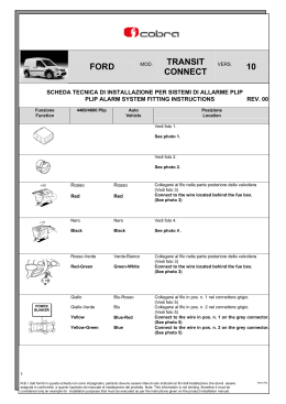
CHEVROLET
MOD.
SPARK
VERS.
10
SCHEDA TECNICA DI INSTALLAZIONE PER SISTEMI DI ALLARME PLIP
PLIP ALARM SYSTEM FITTING INSTRUCTIONS
REV. 00
www.cobra-at.com
Funzione
Function
Serie 44xx Plip
44xx Plip series
Auto
Vehicle
Posizione
Location
Vedi foto 1
See photo 1
Vedi foto 2
See photo 2
Rosso
Rosso-Verde
Collegarsi al filo nel connettore bianco a 22 in valvoliera.
(Vedi foto 3)
Red
Red-Green
Connect to the wire on the 22-way white connector in
the fuse box. (See photo 3)
Nero
Nero
Vedi foto 4
Black
Black
See photo 4
Rosso-Verde
Viola-Nero
Collegarsi al filo da 1,5 mm² nel connettore bianco a 32.
(Vedi foto 5)
Red-Green
Violet-Black
Connect to the 1,5 mm² wire on the 32-way white
connector. (See photo 5)
Giallo
Verde-Grigio
Yellow
Green-Grey
Collegarsi al filo nel connettore bianco a 22 in valvoliera.
(Vedi foto 3)
Connect to the wire on the 22-way white connector in
the fuse box. (See photo 3)
Giallo-Verde
Azzurro-Bianco
Yellow-Green
Light Blue-White
Collegarsi al filo nel connettore bianco a 22 in valvoliera.
(Vedi foto 3)
Connect to the wire on the 22-way white connector in
the fuse box. (See photo 3)
1
N.B. I dati forniti in questa scheda non sono impegnativi, pertanto devono essere ritenuti solo indicativi ai fini dell’installazione che dovrà essere
eseguita in conformità a quanto riportato nel manuale di installazione del prodotto. Note: This information is not binding, therefore it must be
considered only an example for installation purposes that must be executed as per the instructions given on the product installation manual.
cesp10p
Funzione
Function
Serie 44xx
44xx series
Auto
Vehicle
Posizione
Location
Blu-Rosa
Grigio
Collegarsi al filo in pos. n. 18 nel connettore nero a 32 in
valvoliera. (Vedi foto 6)
Blue-Pink
Grey
Connect to the wire in pos. n. 18 on the 32-way black
connector in the fuse box. (See photo 6)
Vedi foto 7
See photo 7
+50
Verde
Verde
Giallo-Viola
Interrompere il filo da 2,5 mm² nel connettore bianco a
32. (Vedi foto 5)
Green
Green
Violet-Yellow
Interrupt the 2,5 mm² wire on the 32-way white
connector. (See photo 5)
N.B. In fase di avviamento misurare che il valore di corrente dove è stata eseguita l’interruzione non superi le caratteristiche
tecniche del prodotto. Eventualmente installare un relè supplementare.
Remark: During the cranking phase, measure the value of the current in the circuit that has been interrupt, to make
sure that it does not exceed the technical specifications of the product.
Install an additional relay if required.
2
N.B. I dati forniti in questa scheda non sono impegnativi, pertanto devono essere ritenuti solo indicativi ai fini dell’installazione che dovrà essere
eseguita in conformità a quanto riportato nel manuale di installazione del prodotto. Note: This information is not binding, therefore it must be
considered only an example for installation purposes that must be executed as per the instructions given on the product installation manual.
cesp10p
Funzione
Function
M
M
+
+
Serie 44xx Plip
44xx Plip series
Auto
Car
Posizione
Location
Giallo-Nero
Grigio
Collegarsi al filo nel cablaggio in uscita dalla porta lato
guida. (Vedi foto 8)
Yellow-Black
Grey
Connect to the wire in the wiring harness coming out
from the driver door. (See photo 8)
Grigio-Nero
Marrone-Giallo
Collegarsi al filo nel cablaggio in uscita dalla porta lato
guida. (Vedi foto 8)
Grey-Black
Brown-Yellow
Connect to the wire in the wiring harness coming out
from the driver door. (See photo 8)
Viola-Nero
Bianco
Collegarsi al filo nel cablaggio in uscita dalla porta lato
guida. (Vedi foto 8)
Violet-Black
White
Connect to the wire in the wiring harness coming out
from the driver door. (See photo 8)
Arancio-Nero
Azzurro-Bianco
Collegarsi al filo nel cablaggio in uscita dalla porta lato
guida. (Vedi foto 8)
Orange-Black
Light Blue-White
Connect to the wire in the wiring harness coming out
from the driver door. (See photo 8)
Programmazione con Morpheus: 44xx Plip – Index 1.
Morpheus setting: 44xx Plip - Index 1.
Cablaggio
Wiring harness
Cablaggio
Wiring harness
Connettore bianco a 22 vie
22-Way white connector
Grigio-Nero
Grey-Black
Giallo-Verde
Yellow-Green
Giallo
Yellow
Giallo-Nero
Yellow-Black
Viola-Nero
Violet-Black
Arancione-Nero
Orange-Black
M
Indicatori di direzione
Direction indicator
Massa
Ground
Massa
Ground
Massa
Ground
3
N.B. I dati forniti in questa scheda non sono impegnativi, pertanto devono essere ritenuti solo indicativi ai fini dell’installazione che dovrà essere
eseguita in conformità a quanto riportato nel manuale di installazione del prodotto. Note: This information is not binding, therefore it must be
considered only an example for installation purposes that must be executed as per the instructions given on the product installation manual.
cesp10p
1
2
3
4
5
4
N.B. I dati forniti in questa scheda non sono impegnativi, pertanto devono essere ritenuti solo indicativi ai fini dell’installazione che dovrà essere
eseguita in conformità a quanto riportato nel manuale di installazione del prodotto. Note: This information is not binding, therefore it must be
considered only an example for installation purposes that must be executed as per the instructions given on the product installation manual.
cesp10p
6
7
8
5
N.B. I dati forniti in questa scheda non sono impegnativi, pertanto devono essere ritenuti solo indicativi ai fini dell’installazione che dovrà essere
eseguita in conformità a quanto riportato nel manuale di installazione del prodotto. Note: This information is not binding, therefore it must be
considered only an example for installation purposes that must be executed as per the instructions given on the product installation manual.
cesp10p
Scaricare