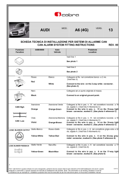
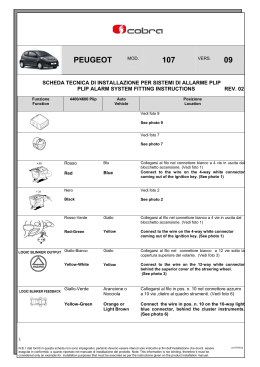
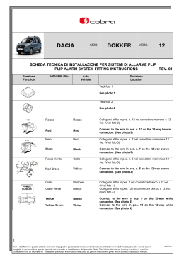
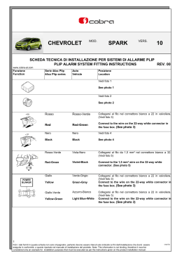
MOD.
FORD
TRANSIT
CONNECT
VERS.
10
SCHEDA TECNICA DI INSTALLAZIONE PER SISTEMI DI ALLARME PLIP
PLIP ALARM SYSTEM FITTING INSTRUCTIONS
REV. 00
Funzione
Function
4400/4600 Plip
Auto
Vehicle
Posizione
Location
Vedi foto 1.
See photo 1.
Vedi foto 2.
See photo 2.
Collegarsi al filo nella parte posteriore della valvoliera
(Vedi foto 3)
Connect to the wire located behind the fue box.
(See photo 3)
Rosso
Rosso
Red
Red
Nero
Nero
Vedi foto 4.
Black
Black
See photo 4 .
Rosso-Verde
Verde-Bianco
Red-Green
Green-White
Collegarsi al filo nella parte posteriore della valvoliera
(Vedi foto 3)
Connect to the wire located behind the fue box.
(See photo 3)
Giallo
Blu-Rosso
Giallo-Verde
Blu
Yellow
Blue-Red
Yellow-Green
Blue
Collegarsi al filo in pos. n. 1 nel connettore grigio.
(Vedi foto 5)
Collegarsi al filo in pos. n. 2 nel connettore grigio.
(Vedi foto 5)
Connect to the wire in pos. n. 1 on the grey connector.
(See photo 5)
Connect to the wire in pos. n. 2 on the grey connector.
(See photo 5)
1
N.B. I dati forniti in questa scheda non sono impegnativi, pertanto devono essere ritenuti solo indicativi ai fini dell’installazione che dovrà essere
eseguita in conformità a quanto riportato nel manuale di installazione del prodotto. Note: This information is not binding, therefore it must be
considered only an example for installation purposes that must be executed as per the instructions given on the product installation manual.
fotrco10p
Funzione
Function
4400/4600 Plip
Auto
Vehicle
Posizione
Location
Blu-Rosa
Blu-Nero
Collegarsi al filo in pos. n. 13 nel connettore grigio.
(Vedi foto 5)
Blue-Pink
Blue-Black
Connect to the wire in pos. n. 13 on the grey
connector. (See photo 5)
Vedi foto 6.
See photo 6.
Verde
Verde
Grigio-Nero
Interrompere il filo nel cablaggio posizionato dietro la
copertura di plastica dello sterzo. (Vedi foto 7)
Green
Green
Grey-Black
Interrupt the wire on the wiring harness located
behind the plastic cover of the steering column.
(See photo 7)
N.B. In fase di avviamento misurare che il valore di corrente dove è stata eseguita l’interruzione non superi le caratteristiche
tecniche del prodotto. Eventualmente installare un relè supplementare.
Remark: During the cranking phase, measure the value of the current in the circuit that has been interrupt, to make
sure that it does not exceed the technical specifications of the product.
Install an additional relay if required.
2
N.B. I dati forniti in questa scheda non sono impegnativi, pertanto devono essere ritenuti solo indicativi ai fini dell’installazione che dovrà essere
eseguita in conformità a quanto riportato nel manuale di installazione del prodotto. Note: This information is not binding, therefore it must be
considered only an example for installation purposes that must be executed as per the instructions given on the product installation manual.
fotrco10p
Funzione
Function
M
4400/4600 Plip
+
Auto
Car
Giallo-Nero
Giallo-Nero
Yellow-Black
Yellow-Black
Posizione
Location
Collegarsi al filo in pos. n. 1 nel connettore blu.
(Vedi foto 5)
Connect to the wire in pos. n. 1 on the blue
connector. (See photo 5)
Bianco-Nero
M
+
Grigio-Nero
Collegarsi al filo in pos. n. 2 nel connettore bianco.
(Vedi foto 5)
Connect to the wire in pos. n. 2 on the white
connector. (See photo 5)
White-Black
Grey-Black
Bianco-Nero
M
+
Collegarsi al filo in pos. n. 4 nel connettore blu.
(Vedi foto 5)
Connect to the wire in pos. n. 4 on the blue
connector. (See photo 5)
White-Black
Viola-Nero
Nero-Verde
Violet-Black
Black-Green
Collegarsi al filo in pos. n. 11 nel connettore grigio.
(Vedi foto 5)
Connect to the wire in pos. n. 11 on the grey
connector. (See photo 5)
Nero-Grigio
Collegarsi al filo nel connettore verde. (Vedi foto 5)
Black-Grey
Connect to the wire on the green connector.
(See photo 5)
Programmazione con Antares: 4400/4600 Plip – Index 1
Antares setting: 4400/4600 Plip - Index 1
Connettore blu
Blue connector
Connettore grigio
Grey connector
Diodo 1N4004
1N4004 diode
Fusibile 3A
3A fuse
Motore baule
Boot motor
Connettore bianco
White connector
Grigio-Nero
Grey-Black
Giallo-Verde
Yellow-Green
Giallo
Yellow
Viola-Nero
Violet-Black
M
Connettore grigio
Grey connector
Connettore verde
Green connector
Diodi 1N4004
1N4004 diodes
Massa
Ground
Diodo 1N4004
1N4004 diode
Massa
Ground
Indicatori di direzione
Direction indicators
Giallo-Nero
Yellow-Black
Massa
Ground
M
Deviatore lato guida e passeggero
Driver and passenger door switch
Massa
Ground
Deviatore baule
Boot switch
Motore porta lato guida
Driver side door motor
3
N.B. I dati forniti in questa scheda non sono impegnativi, pertanto devono essere ritenuti solo indicativi ai fini dell’installazione che dovrà essere
eseguita in conformità a quanto riportato nel manuale di installazione del prodotto. Note: This information is not binding, therefore it must be
considered only an example for installation purposes that must be executed as per the instructions given on the product installation manual.
fotrco10p
1
2
3
4
5
6
7
4
N.B. I dati forniti in questa scheda non sono impegnativi, pertanto devono essere ritenuti solo indicativi ai fini dell’installazione che dovrà essere
eseguita in conformità a quanto riportato nel manuale di installazione del prodotto. Note: This information is not binding, therefore it must be
considered only an example for installation purposes that must be executed as per the instructions given on the product installation manual.
fotrco10p
Scaricare