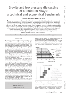
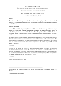
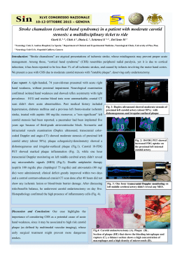
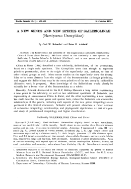
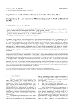
Memorie
Fonderia
Study of the effect of process parameters
on the production of a non-simmetric
low pressure die casting part
A. Pola, R. Roberti
Low pressure die-casting is a "near net shape" foundry process that offers a good compromise between
economical aspects, production rate and casting quality. Because of the constrained position of the gating
system, the application of traditional LPDC process is generally limited to axis-symmetric or symmetric
geometries. The aim of this work was to investigate the low pressure die-casting process in order to define the
effect of various system settings on the production of a sound non-conventional cast component. The research
was supported by the modelling of mould filling and casting solidification, in order to evaluate both the
influence of process parameters and the reliability of the modelling software in the prediction of flow pattern
and thermal history of casting as well as defects formation.
The results were compared with those obtained on an experimental die, completely instrumented, to better
understand the process, validate the calculation procedure and make more confident the use of this tool for
complex parts. Metallographic analyses were also carried out to compare the quality of simulated and real
castings, with particular reference to shrinkage and gas porosity.
KEYWORDS:
LPDC, simulation, filling, pressure influence, AlSi7Mg
INTRODUCTION
Low pressure die-casting (LPDC) is a "near net shape" foundry process in which the molten alloy is poured into a holding pressurized
furnace located below the die table. A feeding tube, called riser or
stalk tube, runs from the furnace to the bottom of the die, as shown
in Fig. 1.
The surface of metal bath in the crucible is pressed by a dry air at
relatively low-pressure (typically in the range of 0.1-1bar) in order
to overcome the difference of metallic pressure between the die
and the surface of the liquid alloy. The molten metal is, therefore,
forced through the stalk tube, feeding the die cavity with low turbulence, also because of the use of a metal filter.
The pressure ramp is increased in order to pressurize the casting
during the solidification, strongly reducing shrinkage porosity.
Once the casting is completely solidified and sufficiently cooled,
the external pressure is released, the molten metal in the riser tube
flows back down into the crucible
by gravity action and the casting is
ejected to allow the next cycle.
Compared with other permanent
mould processes LPDC provides
low levels of scrap (no risers), high
mechanical, metallurgical and technological properties (thanks to
low porosity level), dimensional accuracy, feasibility in using sand
core, etc… together with limited
Annalisa Pola, Roberto Roberti
Universitá degli Studi di Brescia,
Dipartimento di Ingegneria
Meccania e Industriale
[email protected],
[email protected]
la metallurgia italiana - n. 11-12/09
equipment costs.
The gating system is usually positioned in the middle of the casting, correspondent to the centre of the crucible, in order to guarantee uniform pressure and, therefore, flow distribution. This
constrained arrangement imposes the use of traditional LPDC process just for axis-symmetric or symmetric geometries.
Furthermore, the low pressure die-casting subject seems to be not
widely discussed in literature.
For these reasons the present study was aimed to analyse the LPDC
of a non symmetric casting, in order to improve process performance and productivity, investigating the effect of various system
settings (pressure curve, alloy composition within the standard tolerance, melt temperature, etc...) on the production of a sound nonconventional cast component.
To verify whether LPDC may be suitable for manufacturing complex geometries, a good knowledge of metal fluid-dynamic beha-
FIG. 1 Low pressure die-casting process.
Processo di colata in bassa pressione.
57
Memorie
FIG. 2
LPDC machine and the
experimental die (cooling
channels).
Macchina LPDC e stampo
sperimentale (canali di
raffreddamento).
viour into the die cavity is fundamental. The simulation of mould
filling and casting solidification provides a highly useful and reliable tool to rapidly investigate the flow pattern or to easily modify
geometries and process parameters, evaluating their effect on castings quality.
The study was carried out by means of a commercial software (Procast ), considering a standard foundry aluminum-silicon alloy
(AlSi7Mg0.3) whose thermo-fluid dynamics properties needed for
simulation are well known for average chemical composition.
The results were compared with those obtained on an experimental die, available at LKR Laboratory, completely instrumented by
newly developed metal front and temperature sensors to validate
the calculation procedure. Deviations between trials and simulations were analysed, making more confident the use of this tool
for complex parts in the future.
Metallographic analyses were finally carried out to verify the accuracy of the simulation, with particular reference to shrinkage
and gas porosity.
EXPERIMENTAL PROCEDURE
The LPDC machine used for the samples production was a Kurtz
AK92 equipped with a crucible furnace of 125kg capacity (Fig. 2).
Before each tests series 2 samples for emission spectroscopy investigation were taken from the melt to verify the bath composition
and the H2 content.
The die was pre-heated by means of a gas-powered burner for 1-2
hours, in order to reach a sufficiently uniform temperature of ne-
arly 180°C.
The casting geometry consists in a plate characterized by 6 different thicknesses (3 mm, 10 mm, 20 mm, 25 mm, 15 mm and 5
mm) with a not symmetric cavity with respect to the stalk tube,
placed in the middle of the crucible (Fig. 2). This simple configuration allowed to investigate the use of LPDC for the production of
non conventional components and to verify the thermal behaviour
of the die, equipped with an ad hoc designed cooling system consisting in channels flowed with compressed air (pressure of approximately 5,5 bar).
The experimental trials were continuously monitored by means of
6 K-type thermocouples placed inside the mobile half die, 5 mm beneath the surface cavity (Fig. 3), and 8 metal front sensors placed
exactly on the surface of the fixed half mould (Fig. 4) in order to assess the metal flow pattern and to compare this with the simulated one.
At the casting ejection, the surface temperature of casting and die
cavity were also measured by a contact thermocouple.
The investigated process parameters were:
− melt temperature, between 700°C and 740°C;
− alloy composition, changing the elements percentage within
standard tolerance and also considering the effect of modifier
(Sr) and grain refiner (Ti-B) additions on metal fluidity and casting quality;
− pressure curve, in terms of different profiles, as reported in Fig.
5, according to the machine features.
Each trial was named as reported in Table I.
FIG. 3
FIG. 4
Mobile half mould geometry and thermocouples
position.
Geometria del semi-stampo mobile e posizione delle
termocoppie.
58
Sensor distribution inside the half fixed mould.
Distribuzione dei sensori all’interno del semi-stampo
fisso.
la metallurgia italiana - n. 11-12/09
Fonderia
Samples
Chemical composition
Casting T°
Pressure
A
B
C
D
E
F
G
H
Si7.11%, Mg0.4%, Sr, TiB2
Si7.11%, Mg0.4%, Sr, TiB2
Si7.13%, Mg0.4%, Sr, TiB2
Si7.13%, Mg0.4%, Sr, TiB2
Si7.07%, Mg0.4%, Sr, TiB2
Si7.07%, Mg0.4%, Sr, TiB2
Si6.5%, Mg0.2%, Sr, TiB2
Si7.5%, Mg0.2%
740 °C
700 °C
720 °C
720 °C
720 °C
700 °C
720 °C
720 °C
0.4-0.8 bar
0.4-0.8 bar
0.4-0.8 bar
0.4-0.8 or 0.4-0.5 bar
0.4-0.5 bar
0.5-0.6 or 0.6-0.7 bar
combinations of 0.4-0.5, 0.6-0.8 bar
0.6-0.8 bar higher holding time
TAB. I
Investigated process parameters during casting trials.
Parametri di processo indagati durante le prove di colata.
MODEL
The simulation tool used in this study to evaluate the feasibility of
the non symmetric cavity die design is represented by the finite
element ProCast® software, developed by ESI Group.
A FE mesh was created using tetrahedral elements; Fig. 6 shows
shape and mesh of the component.
Temperature dependent thermo-dynamic properties of the casting
alloy (A356) and mould material (H13 steel) used in the analyses
were available in the software database.
Initially the temperature was set to 180°C for all nodes of the die,
according to the data measured by the thermocouples at the end
of the pre-heating period, and equal to 720°C for the liquid alloy,
as detected by the thermocouple dipped into the melt (Table I for
the H family of samples).
The boundary conditions for the calculations were set as follows:
− a heat transfer coefficient, h, equal to 10 W/m2K on all the external surfaces of the die in contact with ambient air;
− a heat exchange coefficient on the air cooling channels walls,
calculated by the well known equation:
Nu = 0.023.Re0.88.Pr0.33 if Re > 6000, Pr > 0.7
FIG. 5
Experimental pressure profiles.
Profili di pressione sperimentali.
[1]
where Re, Pr e Nu are respectively the Reynolds, Prandtl and Nusselt numbers;
− pressure ramp, called inlet boundary condition, at the bottom of
the ingate cylinder, established on the basis of the experimental pressure curves and in particular the pressure curve used for
samples H production (Fig. 5), which resulted to be the best condition during casting trials. It must be noticed that, since the
bottom of the ingate cylinder does not correspond to the liquid
surface in the furnace, the pressure ramp measured in the real
process should be shifted of a ∆P value (Fig. 1), according to the
following equation:
[2]
where ρ is the liquid metal density, ∆h is the height of the metal
into the riser tube with respect to the bath surface, and D and d are
respectively the crucible and riser tube diameter.
EXPERIMENTAL RESULTS
Real steady state thermal conditions were reached after some injections with air cooling enabled; no complete castings were produced in the warm-up period, until steady state conditions were
achieved. In Fig. 7 the warm-up phase of the C production is shown
as an example.
The samples cast at higher melting temperature (A) were completely filled (Fig. 8A), thanks to the increased fluidity with temperala metallurgia italiana - n. 11-12/09
FIG. 6
3D geometry and mesh.
Geometria e mesh 3D.
ture. Notwithstanding the almost complete filling, the A family
samples showed surface defects associated to shrinkage phenomena (piping in the thicker sections) as well as some distortions,
both due to the high melt temperature. Therefore, the A trials set
revealed that, in these working conditions, care must be taken to
59
Memorie
FIG. 7
Measured temperatures during the pre-heating
period.
Temperatura misurata durante la fase di preriscaldo
dello stampo.
obtain sound castings and to preserve the mould.
On the contrary, with a bath temperature of 700°C (B samples) the
reduced fluidity, the lower die temperature and the limited superheating (above Tliquidus) together with the absence of proper
vents could not allow a complete filling of the cavity; particularly,
the thinner section was always partially empty (Fig. 8B). It must
be noticed that the B samples were cast after to the A family, therefore the metal level within the crucible was strongly decreased
and, consequently, experiments should have been carried our
with a new pressure curve.
Based on the previous results, the melt temperature was fixed at
720°C, in order to avoid hot tearing and large shrinkage porosities
as well as early die damage.
The effect of a lower pressure was tested for the production of samples D and E, which resulted uncompleted. The surface of the thinner section (Fig. 9, left side) showed an extended cold wave; the
metal, in fact, seems to divide into two veins that are not perfectly welded, partly because of air entrapment and partly because
of early solidification, probably due to the slow filling associated
to the not proper pressure used.
The F set of samples was cast at a temperature of 700°C, to reduce shrinkage porosity and hot cracks. With this low melting
temperature the previously adopted pressure was absolutely not
suitable to fill the cavity; different pressure curves were then attempted in order to obtain sound castings, notwithstanding the
low melting temperature (i.e. low fluidity) imposed. The samples
F obtained with higher cast pressure showed a quite complete filling (Fig. 9, right side), according to the not optimized die design,
and a quite good surface appearance (very small cracks).
In the last trials, the effect of chemical composition variation on
die filling was investigated.
As well known, silicon is the main aluminum alloying element,
added to improve fluidity, castability and hot tearing resistance as
well as to reduce thermal shrinkage. During the previous tests the
Si content was always fixed at the standard tolerance average value.
For the sixth family of samples (G series) the Si percentage was
FIG. 8
Superficial appearance of first
series of tests,
A (left) and B (right).
Aspetto superficiale della prima
serie di getti prodotti,
A (sinistra)
e B (destra).
FIG. 9
Superficial appearance of
sample D (left) and F
(right).
Aspetto superficiale del
campione D (sinistra) e F
(destra).
60
la metallurgia italiana - n. 11-12/09
Fonderia
FIG. 11 Calculated die temperatures.
Temperature dello stampo calcolate.
FIG. 10 Complete casting, family H.
Getto completo, famiglia H.
maintained at the lower limit acceptable in the standard tolerance.
Notwithstanding the good process control no sound neither complete castings were obtained, revealing the importance of the proper Si level content.
Based on these findings, the last series of tests (H family) were finally cast using the higher Si percentage together with the lower
level of Mg, which can reduce alloy fluidity due to oxidation; moreover, no modifier or grain refiner were added, in order to guarantee a high fluidity. With the imposed pressure curves
completely filled parts were obtained, as shown in Fig. 10.
The results of these experimental trials on a non symmetric are
here summarized:
− steady state thermal conditions are fundamental to guarantee
good quality castings;
− chemical composition must be strictly controlled in order to obtain a high enough fluidity;
− high pressures and/or long holding times allow a complete filling, also when the melt temperature is low or the composition
not strictly controlled. An optimized curve can, therefore, be
found as a function of the other casting parameters, but attention
must be paid at the die closing force in order to avoid excessive
flashes production or, even, dangerous outflow of liquid metal.
Obviously, a compromise between all these parameters must be
defined, depending on the specific working conditions.
SIMULATIONS VS SENSORS RESULTS
The thermal steady state conditions were reached after 12th cycles,
as shown in Fig. 11 on the left where the calculated temperature
profile in the thermocouple positions (5 mm behind the surface
cavity) is compared to that measured by the thermocouples.
It can be noticed that measured and simulated temperatures differ
by roughly 25°C/6%, except TC1 in correspondence of the thinnest section (85°C). This difference is due to the fact that the cycling modelling considers the mould cavity completely filled by the
alloy which releases latent heat of solidification, consequently increasing the die temperature. In the real warm up period the thinner section was not interested by the metal flow, because of the
combination of thin section and cold wall; therefore, this area of
mould was not interested by the metal during filling and solidification, explaining the gap between simulation and experimental
trials.
For the same reason the temperatures measured by the thermocouples, positioned exactly on the mobile die surface, and those simulated after the cycling period show a difference of very few
Celsius degrees (Fig. 12); the good correspondence of results demonstrate the proper description of material thermodynamic data
and correct choice of interfaces and boundary conditions parameters.
Fig. 13 shows the filling patterns obtained numerically at subsequent times. According to the simulation, the alloy enters the cavity through the gate forming a vein which mainly spreads along
the wall of the fixed mobile die filling in the central thicker sections
(25 mm and 20mm). The liquid metal reaches the thinner section
just at the end of the cavity filling; it is divided in two arms, one
FIG. 12 Measured and simulated temperature on the surfaces of the mobile die (H family).
Temperature Misurate e calcolare sulla superficie del semi-stampo mobile (H famiglia).
la metallurgia italiana - n. 11-12/09
61
Memorie
FIG. 13
Simulated fluid flow.
Flusso del metallo simulato.
FIG. 14 Recorded fluid flow.
Flusso del metallo registrato dai sensori.
FIG. 15 Microstructure of the casting, family H area 8.
Microstruttura del getto, famiglia H area 8.
from top the and one from the bottom, that weld around the centre of the thinner section.
These results match well with the experimental data; as shown in
Fig. 14, in fact, there is a close agreement in the fluid flow pattern.
As confirmed by the obtainment of un-complete castings, which
present cavity in the centre of the thinner section area (Fig. 8 –
10) depending on the maximum applied pressure, the simulation
predicts almost correctly also the mould filling.
62
METALLOGRAPHIC INVESTIGATIONS
The quality of the produced casting was analysed by means of metallographic investigation; particularly, the shrinkage porosity as
well as the microstructure, in terms of secondary dendrite arms
spacing (SDAS), were analysed. The samples were cut according to
the scheme showed in Fig. 10.
In the thicker section (area 8) some shrinkage porosity were detected, as already predictable observing the surface depression of
la metallurgia italiana - n. 11-12/09
Fonderia
FIG. 16 Calculated Secondary Dendrite Arms Spacing.
Spazio fra I rami secondary delle dendriti calcolato.
all the samples, as a consequence of an insufficient imposed pressure as well as very high temperature that induces a slow solidification. As an example, in Fig. 15 the microstructure of a sample of
the H family is reported.
The same defect was revealed by the simulation software, demonstrating the good correspondence between calculation and production, also during solidification.
Quantitative metallography measurements resulted in a SDAS of
11.7 m in the thinner section and of 36 µm in the thicker section
for the real cast sample (sections 15 and 8 Fig. 10); as shown in
Fig. 16 the calculated SDAS was very similar to the observed one
(nearly 14 µm and 42 µm respectively).
CONCLUSIONS
The production of a non symmetric component cast by low pressure die-casting process was investigated in order to define the influence of various system settings on the casting quality.
Eight set of samples were produced under different process conditions (melt temperature, pressure ramp and chemical composition within the standard tolerance range) and the process was
continuously monitored by means of thermocouples and pressure
sensors placed inside the mould.
A finite elements model was also developed for the simulation of
die filling and casting solidification.
A good correspondence between simulation and experimental
trials was observed, in terms of die temperature, mould filling and
casting quality.
The results of this study can be summarized as follows:
− simulation is in general a good tool for predicting low pressure
foundry processes,
− temperature and metal front sensors help to understand die filling and validate the simulation procedure, as well as to define
optimum casting conditions;
− thick sections behaviour can be well predicted by simulation
software, but additional phenomena occur at thin sections;
− accurate definition of cycling simulation are needed for thin section;
− small variations in chemical composition can create problems
in thin sections filling;
− LPDC thin parts can be more easily produced provided that no
modifier or grain refiner are added.
ACKNOWLEDGMENTS
The authors gratefully acknowledge the help and the suggestions
by Prof. Helmut Kaufmann and Dr. Werner Fragner, Leichtmetallkompetenzzentrum Ranshofen GmbH (LKR).
REFERENCES
1) JER-HAUR K., FENG-LIN H.and WENG-SING H., Development of an interactive simulation system for the determination of the pressure-time
relationship during the filling in a low pressure casting process,
Science and Technology of Advanced Materials 2, (2001), p.131.
2) HINES J., Determination of interfacial heat-transfer boundary conditions in an Aluminum low-pressure permanent mould test casting, Metallurgical and Material Transactions B, (2003), p 299.
3) MANILAL P.I., SINGH D.P.K. and CHEN Z. W., Computer modelling and
experimentation for thermal control of dies in permanent mold casting, AFS Transactions (2003).
Abstract
Studio dell'effetto dei parametri di processo sulla produzione
di un getto non simmetrico colato in bassa pressione
Parole chiave:
colata in bassa pressione, simulazione, riempimento, AlSi7Mg
Il processo di colata in bassa pressione (o LPDC) è una tecnologia di fonderia cosiddetta “near net shape”, ovvero tale da consentire
l’ottenimento di un pezzo di geometria “prossima alla forma finita” e che richiede un numero limitato di operazioni di finitura;
esso rappresenta un buon compromesso fra aspetti economici, velocità di produzione e qualità del getto. A causa della posizione
del sistema di alimentazione dello stampo, che risulta costruttivamente vincolata, l’applicazione del processo tradizionale LPDC
è solitamente limitato a geometrie assial-simmetriche o comunque simmetriche; tipicamente si producono cerchi in lega.
Lo scopo del presente lavoro è stato quello di studiare il processo di colata in bassa pressione al fine di definire l’effetto dei vari
parametri di produzione (pressione, temperatura del metallo, ecc..) sulla qualità di un getto non convenzionale. La ricerca è stata
supportata dalla simulazione del riempimento dello stampo e della solidificazione del getto, così da valutare sia l’influenza dei
parametri di processo sia la validità della modellazione numerica nella previsione della fluidodinamica di riempimento e della
storia termica di getto e stampo, nonché della formazione di difetti.
I risultati della simulazione sono stati confrontati con quelli ottenuti utilizzando uno stampo sperimentale, completamente strumentato, al fine di comprendere meglio il processo, validare la procedura di calcolo impostata e rendere l’utente più sicuro nell’uso di questo strumento anche per componenti dalla geometria più complessa.
Infine, sono state condotte anche delle indagine metallografiche per confrontare la qualità del getto simulato con quella del prodotto, facendo riferimento in particolare alla porosità da gas e da ritiro.
la metallurgia italiana - n. 11-12/09
63
Scaricare