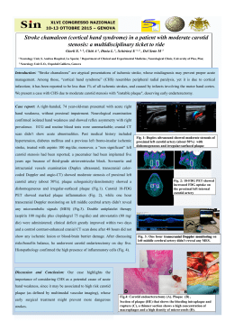
NEWS 207/12 Paradigm shift: New, IP-based headends are ultracompact, highly flexible, easy to operate and extremely reliable. IP revolutionizes headends EMC / FIELD STRENGTH The world’s fastest EMI test receiver reduces testing times SECURE COMMUNICATIONS RADIOMONITORING / RADIOLOCATION Voice encryption device allows tap-proof calls on smartphones Airborne radiomonitoring system opens up an unprecedented range of applications NEWS Published by Rohde & Schwarz GmbH& Co. KG Mühldorfstrasse 15 · 81671 München Regional contact ❙❙ Europe, Africa, Middle East | +49 89 412 9 123 45 [email protected] ❙❙ North America | 1 888 TEST RSA (1 888 837 87 72) [email protected] ❙❙ Latin America | +1 410 910 79 88 [email protected] ❙❙ Asia/Pacific | +65 65 13 04 88 [email protected] ❙❙ China | +86 800 810 8228/+86 400 650 5896 [email protected] www.rohde-schwarz.com Editor and layout: Redaktion Drexl & Knobloch GmbH (German) English translation: Dept. GF-MC7 Photos: Rohde & Schwarz Printed in Germany Volume 52 Circulation (German, English, French, Spanish and Japanese) 75000 approx. three times a year ISSN 0028-9108 Supply free of charge through your nearest Rohde & Schwarz representative Reproduction of extracts permitted if source is stated and copy sent to Rohde & Schwarz München. PD 5214.4365.72 R&S® is a registered trademark of Rohde & Schwarz GmbH& Co. KG. Trade names are trademarks of the owners. CDMA2000® is a registered trademark of the Telecommunications Industry Association (TIA-USA). The Bluetooth® word mark and logos are registered trademarks owned by Bluetooth SIG, Inc. and any use of such marks by Rohde & Schwarz is under license. “WiMAX Forum“ is a registered trademark of the WiMAX Forum. “WiMAX,“ the WiMAX Forum logo, “WiMAX Forum Certified,“ and the WiMAX Forum Certified logo are trademarks of the WiMAX Forum. All other trademarks are the properties of their respective owners. Cover feature From the broadcasting studio to the antenna, Rohde & Schwarz offers a nearly complete range of equipment and systems developed and produced by the company itself. Now one of the few remaining gaps has been closed: Rohde & Schwarz has developed and launched an innovative type of headend. The company’s initial focus for the new headends is on DVB. They revolutionize headend architecture: Instead of using numerous, separate devices, the new headends rely on extremely compact, high-performance IT hardware. All core functionality is software-implemented for high flexibility. Signal flow within the headends is fully based on the Internet protocol (IP). Only just on the market, the new headends were already prize winners: Introduced at IBC 2012 in Amsterdam, they won the coveted TV Technology STAR Award (page 54). Overview NEWS 207/12 WIRELESS TECHNOLOGIES GENERAL PURPOSE EMC / FIELD STRENGTH Testers Test systems Test receivers W R&S®CMW500 wideband radio communication tester R&S®CMWcards simplifies the creation of wireless signaling tests.....................6 W R&S®TS6110 W R&S®ESR Convenience in the lab: LTE fading simulator for the R&S®CMW500...........9 Network analyzers Spectrum/signal analyzers W R&S®FSW infotainment test system Scalable infotainment test system – ready for any task............................... 16 EMI test receiver W R&S®ZVA vector network analyzer Noise figure measurement on frequency-converting DUTs............... 19 signal and spectrum The world’s fastest EMI test receiver drastically reduces testing times........ 22 analyzer Efficient testing of multistandard base stations............... 12 Broadband amplifiers W R&S®BBA100 Its modular hardware and software makes the broadband amplifier Now with up to 2 kW and new options........................................ 28 R&S®TS6110 infotainment test system adaptable to virtually all development and quality assurance requirements (page 16). The revolutionary R&S®CMWcards user interface for the R&S®CMW500 enables users to effortlessly create specification-compliant signaling protocol test sequences (page 6). 4 BROADCASTING SECURE COMMUNICATIONS RADIOMONITORING / RADIOLOCATION Audio/video testers Crypto products COMINT systems W R&S®VTC W TopSec W Airborne video test center Mobile voice encryption device Smart and secure: tap-proof voice calls on smartphones................ 43 DA42M-NG COMINT system Highflyer: reliable radiomonitoring from the air......................................... 46 W R&S®RAMON New model plus modules for HDMI and analog A/V interfaces....... 31 Locate software Help in the urban jungle: reliable direction finding in urban areas......................................... 51 Signal generators W R&S®CLG cable load generator In brief................................................ 34 MISCELLANEOUS TV analyzers W R&S®ETC compact TV analyzer In brief................................................ 35 W Masthead............................................2 W Newsgrams...................................... 54 Audio/video headends W R&S®AVHE100 A/V headend Paradigm shift on the headend market: the new R&S®AVHE100 from Rohde & Schwarz........................ 36 Rohde&Schwarz radiomonitoring systems in airborne platforms open up a wide range of potential applications (page 46). NEWS 207/12 5 WIRELESS TECHNOLOGIES | Testers R&S®CMWcards simplifies the creation of wireless signaling tests 2G, 3G, 4G: Developers are having to prepare an increasing number of ever more complex test cases. And this requires expertise in both programming and protocols. Or it did until now: The revolutionary R&S®CMWcards user interface for the R&S®CMW500 enables users to effortlessly create specificationcompliant signaling protocol test sequences. Customized operating concepts and programming interfaces The R&S®CMW500 wideband radio communication tester has truly earned the right to be called a multistandard test platform. Thanks to its wide range of test capabilities, the R&S®CMW500 can thoroughly test user equipment for compliance with practically all wireless communications standards – as an RF and signaling protocol tester in development or as a production tester. The tester comes with customized operating concepts and programming interfaces for all of these complex applications. The RF tester’s front panel man-machine interface (MMI), for example, has proven its value. This intuitive user interface gives users convenient control of measurements and application tests for all major wireless communications standards. In R&D, the LLAPI / MLAPI programming interfaces for C++ and the TTCN-2 / TTCN-3 notation languages commonly used in conformance testing are the first choice for compliance testing of mobile phone protocol stacks using complex signaling sequences. However, this requires knowledge of both programming and protocols. It places an additional burden on developers who need to concentrate on functional tests and reproducing problems originating from real-world mobile communications networks and do not always want to deal with programming testers. And now they don’t have to. The revolutionary new R&S®CMWcards user interface, which resembles a card game, helps users set up functional signaling sequences (Fig. 1). Fig. 1 The R&S®CMW500 with the R&S®CMW-CU control unit. R&S®CMWcards, the revolutionary new user interface shown on the monitor, enables users to quickly and reliably create functional signaling sequences without programming experience. 6 WIRELESS TECHNOLOGIES | Testers Advantages of R&S®CMWcards ❙❙ Graphical test script development tool ❙❙ No programming knowledge required ❙❙ Hopscotch wizard and clear “playing card rules” ❙❙Test script creation, parameterization, execution and analysis in a single tool ❙❙ Inter-RAT procedures for LTE, WCDMA, GSM and CDMA2000® planned Fig. 3 The hopscotch wizard simplifies selection of the various protocol procedures. Playing cards, a visual aid for setting up test procedures With the R&S®CMWcards user interface, users simply drag and drop cards to create and configure wireless communications cells. The cards make it very easy to represent protocol procedures and to prepare and parameterize signaling sequences. A software wizard helps users arrange specification-compliant message sequences, interactively guides them through the test script and warns them of errors. There is no compilation of programming code. Once the user has finished creating the scenario, the test case can be immediately executed on the R&S®CMW500. Clear rules and an intelligent protocol wizard Like any card game, R&S®CMWcards has rules. Color-coded cards ensure that the created test sequences are always practical and useful, even for highly complex protocol procedures. To create a specification-compliant test case, the user simply has to match the colors on the cards when setting up the sequence. This is illustrated in Fig. 2. Here, the cards are placed in a correct sequence. Green is followed by green, blue by blue, etc. An additional aid – the hopscotch wizard – abstracts the different user equipment states from the 3GPP specification into a geometric hopscotch arrangement (Fig. 3). The wizard reduces the card pool, only offering the cards that put the DUT into the desired protocol state. Perfect overview: card types, parameterization and views R&S®CMWcards distinguishes between different types of cards: setup, procedure, general and MMI cards. Setup cards, for instance, are used to define the environment that will be tested, e.g. network cells, SIM cards or even channel settings. The R&S®CMWcards user interface employs an integrated approach. It combines configuration of the R&S®CMW 500, setup, execution and monitoring of signaling tests, and protocol analysis all in a single program. A wide range of views are provided. In the parameter view, all configurable parameters can be graphically set using drop down lists and input fields. The network view shows the test case’s current cell configuration. And the message sequence chart displays the layer-3 signaling message sequences that are exchanged between the tester and the device under test (Fig. 4). Fig. 2 Color-coded cards ensure specification-compliant signaling test scenarios. NEWS 207/12 7 WIRELESS TECHNOLOGIES | Testers The interactive path to success Summary R&S®CMWcards provides a comprehensive pool of cards for a wide variety of signaling procedures for LTE, WCDMA, GSM and CDMA2000®. The user can drag the cards directly from the pool onto the “playing field” and arrange them in a sequence (Fig. 4). The protocol wizard mentioned previously helps the user create scenarios. R&S®CMWcards is the ideal lab tool, particularly for throughput measurements, handover tests, inter-RAT procedures and IMS VoLTE, including CS fallback (CSFB) and SRVCC. Just like conventional protocol test cases, the messages transmitted in the test case between the mobile phone and the network are collected in the message log. This log can be compared with the expected message sequence from the message sequence chart. R&S®CMWcards closes the gap between callbox-related applications and the powerful C++ and TTCN protocol test frameworks on the R&S®CMW500. The intuitive graphical interface is easy to learn and requires no programming experience, enabling users to quickly and reliably create functional signaling sequences. Manuel Galozy; Thomas Moosburger R&S®CMWcards comes with a large number of sample test scripts that allow the user to quickly begin testing fundamental signaling procedures and greatly simplify the creation of new scripts. Fig. 4 View of the entire R&S®CMWcards application with card pool, playing field and monitor view (here the message sequence chart, MSC). 8 WIRELESS TECHNOLOGIES | Testers Convenience in the lab: LTE fading simulator for the R&S®CMW500 The combination of the R&S®AMU 200A fading simulator and the R&S®CMW500 wideband radio communication tester is the ideal solution for the sophisticated user-defined simulation of fading conditions. However, if the main focus is on routine measurements in accordance with the LTE fading profiles defined by 3GPP, the R&S®AMU200A is not required: The R&S®CMW500 can simulate fading and AWGN with the new R&S®CMW-KE100 and R&S®CMW-KE500 options. Internal fading simulator in the R&S®CMW500: convenient and time-saving Practically any standard-compliant and user-defined simulations of the fading characteristics of radio channels can be carried out with an external baseband signal generator and fading simulator such as the R&S®AMU 200A from Rohde & Schwarz. The instrument has a convenient user interface that has been optimized for this purpose and helps users to quickly and reliably define the many parameters that need to be set. However, in everyday lab operations the main focus is not always on such sophisticated user-defined simulations of fading conditions. In many cases, routine tests using defined fading profiles from the test specifications including additive white Gaussian noise (AWGN) are sufficient. For such tests, users obviously prefer performing the most important receiver measurements directly using the radiocommunications tester. For this reason, Rohde& Schwarz has developed an integrated fading simulator for the R&S®CMW500 wideband radio communication tester. The simulator allows the user to select the required defined fading profiles from the test specifications and measure the data throughput, the block error rate and the channel characteristics (e.g. CQI). The new option provides a high degree of convenience, since the fading simulator is fully integrated in the user interface and the remote control command set of the R&S®CMW500. The tester superimposes the fading profile onto the d ownlink signals in the baseband, before mixing them onto the c arrier frequency. Power calibration by the user is not necessary, because the tester internally balances the insertion loss that the fading module applies to the downlink signal. In remote control operation, the internal fading simulator is configured using commands that correspond to the s ignaling syntax, but are essentially compatible with the commands of the R&S®AMU 200A. This is documented by the following example of the remote control command, which calls up the “extended vehicular A” fading profile with 5 Hz Doppler frequency and medium MIMO correlation for LTE: For the R&S®AMU 200A SOURce<hw>:FSIMulator:STANdard EV5Medium For the R&S®CMW500 CONFigure:<FWA>:FADing:FSIMulator:STANdard EV5Medium Fading simulation with the R&S®AMU200A – the comprehensive solution for all requirements The 3GPP standardization committee has adopted test specifications that define fading profiles for the different mobile radio standards to be used in receiver tests. These include fading profiles for the following standards: ❙❙ LTE TS 36.101 annex B, ❙❙ WCDMATS 25.101 annex B.2, ❙❙ GSM TS 45.005 annex C.3. The R&S®AMU200A baseband signal generator and fading simulator supports all of the fading profiles defined in the test specifications of the respective mobile radio standards. When it comes to performing user-specific tests, the R&S®AMU200A is indispensable. It allows users to select the parameters of a fading profile and define taskspecific profiles. To perform the measurements together with the R&S®CMW500, the R&S®AMU200A is connected to the tester via the digital TVR290 interface. The R&S®AMU200A fades the downlink signal and adds the AWGN. This is all done digitally in the baseband. NEWS 207/12 9 WIRELESS TECHNOLOGIES | Testers Fading initially for LTE The R&S®CMW500 internal fading simulator is initially available for LTE signaling. Figs. 1 and 2 show the supported fading profiles and the user interface. Tests with fading are indispensable, particularly in combination with the MIMO functionality of LTE, because MIMO reception depends very much on the channel characteristics. Moreover, the support of MIMO is mandatory for all LTE terminals in category 2 and above. The fading simulator can simulate the correlation between the individual propagation paths. The correlation is used at three levels in the 3GPP profiles: low, medium, high. Depending on the intensity of the correlation, it is advisable to use transmit diversity (transmission mode 2) or spatial multiplexing (transmission modes 3, 4) in LTE. Fig. 3 shows that with identical fading profiles, measurements using the R&S®CMW500 with the internal fading simulator produce practically the same results as measurements using the R&S®AMU200A: There is virtually no difference between the traces of the block error rate versus the signal-to-noise ratio. Supported fading profile Number of channel taps Delay spread (RMS) Doppler frequency Extended pedestrian A (EPA) 7 45 ns 5 Hz Extended vehicular A (EVA) 9 357 ns 5 Hz 70 Hz Extended typical urban (ETU) 9 991 ns 70 Hz 300 Hz Channel quality indicator (CQI) High-speed train (HST, end of 2012)) 2 1 318 ns – 0 Hz and 5 Hz 750 Hz MIMO correlation Low Medium High Low Medium High Low Medium High – – Fig. 1 The p rofiles supported by the internal fading simulator of the R&S®CMW500. Fig. 2 The user interface of the f ading simulator in the R&S®CMW500. 10 WIRELESS TECHNOLOGIES | Testers ETU, 300 Hz, medium correlation, QPSK, TBS idx. 9 100 100 90 90 80 80 BLER in % BLER in % EPA, 5 Hz, low correlation, QPSK, TBS idx. 9 70 60 70 60 50 50 40 40 30 30 20 20 10 10 3 3.5 4 4.5 5 5.5 6 6.5 7 7.5 8 8 8.5 9 9.5 10 SNR in dB 10.5 11 11.5 SNR in dB Fig. 3 Comparison of block error rate measurements for different fading profiles, using the internal fading simulator of the R&S®CMW500 (red) and the R&S®AMU200A fading simulator (blue). TBS idx. 9: transport block size index. Summary The fading simulator for the R&S®CMW500 provides the 3GPP fading profiles for LTE receiver tests. The simulator is an ideal alternative for users who wish to utilize signaling and fading in a convenient and user-friendly way in a single instrument, Fading – the most important details in brief A common model for emulating a mobile radio channel is the tapped delay line. The model is generated using a finite impulse response (FIR) filter with time-dependent filter coefficients (Fig. 4). It takes into account that clusters of partial waves of a certain delay t are formed in real propagation scenarios, which results in smearing of the receive signal in the time domain (delay spread). In addition, the Doppler effect causes smearing of the receive signal in the frequency domain (Doppler spread). This is taken into account in the model by means of suitable spectral forming of the filter coefficients. The Clark bathtub model, often called the classic Doppler spectrum, is typically used here. If the real and imaginary parts of the filter coefficients have Gaussian distribution, this is referred to as Rayleigh fading. Another important aspect of mobile radio channel simulators is additive white Gaussian noise (AWGN). at an attractive price. To support the multistandard capability of the R&S®CMW500, the simulator is planned to be also offered for other mobile radio standards (2G, 3G, CDMA2000® 1xEV-DO). Thomas Braun; Stefan Schmidt A fading channel of this type is found between every pair of transmit and receive antennas in MIMO systems. These channels are not usually independent, but have a statistical correlation. The correlation is dependent upon various parameters, e.g. the type of the antenna arrays at the transmitter and the receiver, the radiation patterns and the distance between the antenna elements, as well as the main reception directions and the power distribution. Tapped delay line x(k) τ1 h1(k) τ2 h2(k) …………… τM hM(k) ∑ y(k) Fig. 4 FIR fading channel model. NEWS 207/12 11 WIRELESS TECHNOLOGIES | Spectrum / signal analyzers R&S®FSW: efficient testing of multistandard base stations The R&S®FSW signal and spectrum analyzer with the multistandard radio analyzer (MSRA) mode allows developers to examine the mutual influence between signals of different standards. The MSRA mode significantly simplifies troubleshooting during the development of multistandard base stations (BTS). Demanding tests: measurements on multistandard base stations 3GPP has standardized the measurements on m ultistandard BTS in specifications TS 37.104 and TS 37.141 for GSM / EDGE, WCDMA/ UMTS, TD-SCDMA and LTE. TS 37.104 defines the minimum requirements for the air interface, and TS 37.141 defines the test scenarios. Compared with classic base stations, the quantity and complexity of test scenarios for multistandard BTS are significantly more extensive – placing considerably higher demands on test systems with regard to measuring speed and adjustable parameters. Signal and spectrum analyzers such as the R&S®FSW, R&S®FSQ and R&S®FSV from Rohde&Schwarz can perform the required transmitter measurements, e.g. spurious emissions, out-ofband emissions and adjacent channel leakage ratio. A comprehensive range of application options allows these measuring instruments to analyze and demodulate the signals of the GSM, WCDMA, LTE FDD/ TDD and TD-SCDMA wireless communications standards, effectively covering all of the test scenarios in TS 37.141. Measuring applications are also available for CDMA2000®, which is widely used throughout North and South America and parts of Asia. Measurements on multistandard BTS can be problematic: Since the stations use the same RF components to simultaneously transmit different standards on adjacent carriers in the same frequency band, there is a risk of mutual influence between the signals. It is vital to identify such interference during optimization and troubleshooting. The classic sweep mode is not ideal for such tasks, since the spectrum and the signals of different standards are sequentially analyzed in this mode. The detector measures the level at a certain point in time at a certain frequency, and cannot detect short-term interference outside this range. This makes it significantly more difficult to identify mutual interference between the signals. Pulsed, non-correlated signals are particularly difficult to detect, since a complete pulse may not have been captured. The multistandard radio analyzer in the R&S®FSW signal and spectrum analyzer solves this problem. The R&S®FSW signal and spectrum analyzer provides an a nalysis bandwidth of 160 MHz. Its special operating mode, the multistandard radio analyzer, is indispensable for developers of multistandard wireless communications base stations or frequency-agile radio systems and their components. This article describes the MSRA in detail. The R&S®FSW was presented in detail in NEWS (2011) No. 204 in a special supplement in the middle of the magazine. 12 WIRELESS TECHNOLOGIES | Spectrum / signal analyzers Cost pressures force development of universal base stations Base stations that have been specially developed for a specific standard or a particular frequency band are not in step with the times. This is due to the rapid development of wireless communications since the introduction of the GSM standard 20 years ago: Voice services were soon followed by data services, and over the course of time increasingly powerful wireless communications standards such as UMTS, HSPA+ and LTE have emerged. Originally, each standard had its own frequency band. However, depending on the country and the range of standards that are used there, this situation is becoming Multistandard radio analyzer (MSRA) In the MSRA operating mode, the R&S®FSW signal and spectrum analyzer fully analyzes the multistandard signal within the selected frequency and time interval. This makes it easy to locate interference between signals of different standards. The MSRA makes it possible to capture signal data with a 200 Msample depth. At an analysis bandwidth of 160 MHz, data can be captured for up to one second. increasingly blurred: As a result of technical advancements, different standards are sometimes operated on the same frequency bands – a trend that is certain to continue. Due to this rapid development, network infrastructures often have many (expensive) parallel paths. When UTMS was introduced, most countries already had an extensive GSM network that could also be used for UTMS. However, new components also had to be added and these were often from different manufacturers. Today, network expansion, maintenance and network management for GSM and UMTS still often take place separately, and are therefore duplicated – with the associated costs. When users open a new measuring application on the R&S®FSW, they decide whether to use the MSRA (Fig. 1). If they choose to use the MSRA, all other applications that they open will use the same I/Q data. A special feature of the MSRA is MSRA View. In this view, all measuring windows of the individual applications are displayed simultaneously, with measurements that have been carried out at the same time. The analysis line (AL) always has the same chronological position within the acquired I/Q data block in all applications, making it easy to identify time correlations. Fig. 1 Numerous measuring applications for wireless communications standards, general vector signal analysis and analog demodulation are available in MSRA mode. NEWS 207/12 13 WIRELESS TECHNOLOGIES | Spectrum / signal analyzers Example The following example demonstrates how the MSRA mode helps to analyze errors on a multistandard radio signal. First, we look at the signal in the “MSRA Master” view (Fig. 2). The signal consists of two GSM carriers, one UMTS carrier and one LTE carrier. The markers show the limits of the analysis range of the individual measurements. The individual measurements are opened using the tabs. Next, we look at the UMTS measurements using the “3G FDD BTS” tab (Fig. 3). In this example, the Composite EVM and EVM vs. Chip measurements have been opened. It is evident that slot 1 is showing an unexpectedly high EVM value. This value is an important key attribute when developing and optimizing systems for digital wireless transmission and an indicator of the quality of the digitally modulated signal. Values that are too high lead to a higher error rate and therefore a slower Fig. 2 Display of a multistandard radio signal in MSRA mode; the signal consists of two GSM carriers, one UMTS carrier and one 5 MHz LTE carrier. Fig. 3 UMTS measurement showing the Composite EVM and EVM vs. Chip measurements. Slot 1 is highlighted in color in the Composite EVM view (top), and examined in detail in the EVM vs. Chip view (bottom). 14 WIRELESS TECHNOLOGIES | Spectrum / signal analyzers Fig. 4 View of GSM measurement in MSRA mode. The display shows the level versus time. Two GSM bursts are visible. The analysis line is on the rising edge of the second GSM burst. data rate. As of a certain threshold, which depends on the type of modulation, data transmission is no longer possible. A detailed examination reveals that the high EVM value is caused by defective chip 1878. Since this display is on the time axis, the orange analysis line can be placed exactly on this chip and is therefore positioned at 6.31 ms. By switching to the MSRA view of the GSM measurement (Fig. 4) with the magnitude capture display (level vs. time), the offender is revealed. The analysis line at 6.31 ms is now positioned exactly on the rising edge of the GSM burst. It is obvious that this edge is the reason for the increased EVM value of the UMTS signal. Simultaneous analysis of the signals in MSRA mode enables users to easily identify the cause of interference in the UMTS signal. Summary The advantages of multistandard BTS are obvious: Network operators can use them to transmit signals of different standards using the same infrastructure, cutting the cost of installation, maintenance and management of their networks. However, multistandard BTS place higher requirements on measuring systems with respect to measuring speed, adjustable parameters and test scenarios, as specified in 3GPP TS 37.141. Optimization and troubleshooting that extend beyond the TS 37.141 specification require methods for analyzing the time correlation between signals of different standards. Thanks to the combined measurement within a time and frequency range, the MSRA mode of the R&S®FSW allows manufacturers of multistandard BTS to visualize errors that were previously very difficult to detect. Martin Schmähling Without the R&S®FSW analyzer’s MSRA mode, such an analysis would be much more complicated. Either a second, timesynchronized and triggered spectrum analyzer would be needed, or the captured data would need to be analyzed using complex external signal processing software. The MSRA mode makes troubleshooting significantly easier and faster, and only one measuring instrument is required – the R&S®FSW. NEWS 207/12 15 GENERAL PURPOSE | Test systems Scalable infotainment test system – ready for any task Infotainment components for automobiles and for the home are becoming increasingly complex. As a result, test environments for development and quality assurance must grow in flexibility accordingly. Thanks to its modular hardware and software, the R&S®TS6110 infotainment test system is an excellent example of how to keep pace with the requirements. Infotainment systems – more complex than ever Infotainment test systems are facing a very diverse set of challenges today. The reason lies with the wide variety of instruments on the market. On the one hand, there are the conventional AM and FM receivers and components such as amplifiers, CD players and tuners. On the other hand, increasingly complex infotainment components and systems are being developed that cover a wide range of digital sound and television broadcasting standards (Fig. 1). As more of these systems are networked, network standards such as LAN, WLAN and Bluetooth® come into play. In addition, telephones, navigation systems and bus systems such as CAN or MOST are important components in today’s automobiles. All of which translate into a diverse set of requirements that are covered by a test solution adaptable to any task: the R&S®TS6110 infotainment test system (Fig. 2). Wireless Digital communications Audio DAB, DAB+, Navigation Amplifier DMB AM (MW, HD GPS CD LW, SW) RDS SDARS XM GSM, UMTS CR TMC SDARS LTE MP3 SIRIUS TPEG Bluetooth®, WLAN Auxiliaries Analog FM TMC Miscellaneous Climate rack control Current and voltage measurement CAN bus control MOST bus control MS Word report generator MOST Fig. 1 Functional scope of the R&S®TS6110 infotainment test system. Fig. 2 Example of a test system with three transmitters for AM and FM tests. 16 GENERAL PURPOSE | Test systems R&S®TS 6110 configuration Signal generator 1 FM, AM, RDS, TMC Radiocommunications tester GSM, 2G … 4G, LTE, WiMAX™ Signal generator 2 and 3 FM, AM, RDS, TMC Bluetooth® tester Signal generator 4 HD, XM, Sirius, GPS Test adapter DAB / DMB content server Signal generator 5 DAB, DAB+, DMB DVB content server Signal generator 6 DVB Audio analyzer and generator, analog, digital DC power supply … 40 V / … 40 A Process controller IEEE, LAN, CAN, MOST WLAN protocol tester Voltmeter, ammeter DUT MOST (digital audio signals) Optional components Fig. 3 Basic block diagram showing additional hardware modules – together with the test adapter, the blue components form the most common base configuration of the R&S®TS6110 for car radio tests. Modular and adaptable to every test task The hardware of the R&S®TS 6110 is modular, making it adaptable to specific test requirements. Combinations ranging from desk units with only a few instruments all the way up to systems comprising multiple 19" racks are possible. Fig. 3 provides an overview of the various components that can be integrated into the R&S®TS 6110. Virtual drivers are used to adapt the hardware to the software. The test system can be expanded as needed, making it ready for future generations of instruments. The DUT is connected centrally via a test adapter (Fig. 4), making time-consuming modifications in between the measurements unnecessary. Software modules can be combined as needed to meet the individual test requirements; Fig. 1 shows the functional scope of the R&S®TS6110 infotainment test system. Fig. 4 The R&S®CRTA02 standard test adapter; additional test adapters are available. NEWS 207/12 17 GENERAL PURPOSE | Test systems Fig. 5 User interface. User interface: building test sequences using drag & drop The test software can generate both individual measurements and test sequences without any programming knowledge on the part of the user. The individual measurements are configured using input dialogs (Fig. 5) and then dragged and dropped into test sequences. These test sequences can be saved, making the test results transparent and reproducible at any time. The required settings on the DUT are typically made automatically via the CAN bus. In the case of DUTs without a bus, a window appears on the screen instructing the user to make the required settings (Fig. 6). Documentation of test results Every measurement is logged in detail. In addition, limit values can be predefined and evaluated automatically for all measurements. The results are output on the screen during the measurement and saved in Excel™ format at the end of 18 Fig. 6 User interface for manual power balancing. the test. These files can be used to generate individual reports. Graphs are copied to other programs by using drag & drop. With the MS Word report generator option, users can automatically create individual test reports in Word™. As the successor to the car radio test system, which has maintained a successful presence in the market for many years, the R&S®TS6110 infotainment test system is a flexible, future-ready platform for the development and quality assurance of infotainment components and systems. Heinz Heußen GENERAL PURPOSE | Network analyzers The R&S®ZVA measures noise figure on frequency-converting DUTs The R&S®ZVA vector network analyzers with the R&S®ZVAB-K 30 option provide noise figure measurements. Equipped with the new R&S®ZVAB-K31 option, the analyzers measure noise figure also on frequencyconverting components and modules with access to the DUT’s local oscillator (LO). Both options operate independently of an external noise source. A new approach to a familiar task Measuring the noise figure is essential when c haracterizing components such as amplifiers, mixers or receivers. The R&S®ZVA vector network analyzers carry out this measurement up to 67 GHz without an external noise source, with the benefit that the system-inherent low measurement uncertainty is maintained since it is not affected by such sources. Noise figure measurement Signal + noise Signal ¸ZVA Digital signal processing The analyzers directly measure the signal-to-noise ratio (SNR). This lets users determine the noise figure of frequency-converting components – plus other relevant quantities such as S-parameters – without requiring RF switches or modifications to the test setup. Filter NCO The noise figure is defined as follows: A/D Noise figure = SNRinput ⁄ SNRoutput The R&S®ZVA uses one of its internal generators to stimulate the DUT (Fig. 1). It determines the signal-to-noise ratio at the DUT output, based on the total power of the measured signal (including noise power) within the measurement bandwidth and the signal with the noise power removed. The signal-tonoise ratio at the DUT input is determined by means of analyzer LO DUT Fig. 1 For noise figure measurements with the R&S®ZVA, a signal from one of the analyzer’s internal generators is fed to the DUT. The R&S®ZVA vector network analyzers are the high-end models in the Rohde &Schwarz network analyzer portfolio. They are available as two-port and four-port models and for different frequency ranges. The R&S®ZVA 67 shown here covers the frequency range from 10 MHz to 67 GHz. It has four internal sources, allowing fast and convenient measurements on amplifiers, mixers and transmit / receive modules with two converter stages. In addition to excellent technical data, the R&S®ZVA analyzers offer numerous, partly unique measurement capabilities. For more information, visit www.rohde-schwarz.com (search term: ZVA) NEWS 207/12 19 GENERAL PURPOSE | Network analyzers calibration. The graphical user interface of the R&S®ZVA-K31 option guides the user through the required steps for a test setup and the individual calibration steps for determining the power level and SNR of the individual paths (Fig. 2). Effect of image frequency on measurement results For frequency-converting measurements, the intermediate frequency (IF) is obtained as follows: IF = |RF ± LO| Fig. 3 shows that the total noise power at the IF is the sum of the RF noise power and the image frequency noise power. Depending on the DUT, the IF noise power can vary over the frequency range to be measured or differ from the RF noise power. Fig. 4 shows an example of this – a DUT consisting of an amplifier and a mixer. The noise powers of the RF and image frequency are determined by the amplifier characteristics. Fig. 2 A straightforward GUI guides the user to the desired calibration setup. Noise power at the IF Fig. 3 The total Thermal noise RF noise power at the IF is the sum of the RF noise power and the image frequency noise power. DUT Amplifier Mixer LO Fig. 4 Example of a DUT in which the RF and image frequency noise powers can vary as a function of the amplifier’s noise matching and frequency response. Fig. 5 Definition of test setup and frequencies to be used. 20 LO Image frequency f Thermal noise IF f GENERAL PURPOSE | Network analyzers Fig. 6 Measurement of a DUT consisting of an amplifier and a mixer (example shown in Fig. 4). The noise figure and gain (S21) are measured using the same test setup; no modifications are required. R&S®ZVA: noise figure measurements made easy Summary The R&S®ZVAB-K 31 option automatically corrects results by eliminating the unwanted effect of the image frequency. For this purpose, the network analyzer measures the total noise power at each test frequency and corrects the noise figure accordingly. The R&S®ZVAB-K31 option makes it possible to measure the noise figure on frequency-converting components and modules up to 67 GHz. The option enables full characterization of components and modules using a single test setup. The DUT’s noise figure, S-parameters and gain can be displayed in a single diagram. Volker Herrmann Activating the image frequency noise power correction is useful only when the image frequency is within the analyzer’s operating frequency range. The R&S®ZVA indicates the range in which the image frequency occurs. The R&S®ZVAB-K 31 has a straightforward, graphical dialog window for configuring the test setup and measurement, including the frequencies to be used (Fig. 5). The DUT ports can be assigned to the analyzer ports. The DUT type, i.e. upconverter or downconverter, is defined in this window. The analyzer also supports external signal generators. Fig. 6 shows, as an example, the measurement results obtained for a DUT as presented in Fig. 4 (amplifier and mixer). Noise figure and gain (S21) are measured using the same test setup. NEWS 207/12 21 The R&S®ESR as part of a compact EMC measurement system including EMI and EMS test equipment and components for system control. 22 EMC / FIELD STRENGTH | EMI test receivers The world’s fastest EMI test receiver drastically reduces testing times The new R&S®ESR EMI test receiver uses an FFT-based time domain scan to perform standard-compliant disturbance measurements up to 6000 times faster than conventional EMI test receivers. It offers a wide range of diagnostic tools such as realtime spectrum analysis, spectrogram, persistence mode and IF analysis that effectively help users identify and eliminate disturbances. More speed, more insight, more intelligence The R&S®ESR (Fig. 1) is an EMI test receiver for the frequency range from 10 Hz to 7 GHz (Fig. 2). Its main focus is on product certification measurements in line with relevant commercial EMC standards. With its integrated preselection, a 20 dB preamplifier and a highly linear frontend, the R&S®ESR meets the requirements of the CISPR 16-1-1 standard and also complies with all other relevant commercial standards. What makes the instrument truly outstanding is its FFT-based time domain scan that measures electromagnetic disturbances at a speed so far unattained. Disturbance measurements which took hours in the past can now be completed in just seconds. Featuring optional realtime spectrum analysis with a wide range of diagnostic tools, the instrument provides new insight into disturbance signals and their history. Besides offering EMC testing functionality, the R&S®ESR is a full- featured, powerful signal and spectrum analyzer for lab applications. The instrument comes with a clearly structured, intuitive touchscreen interface that makes it very easy to operate in any mode. Time domain scan for ultrafast, standard-compliant measurements In the time domain scan mode, the R&S®ESR measures up to 6000 times faster than in the conventional, stepped frequency scan mode, making it the fastest EMI test receiver in the marketplace. The R&S®ESR performs frequency scans in R&S®ESR models 10 Hz 9 kHz 3.6 GHz 7 GHz ¸ESR3 ¸ESR3 with ¸ESR-B29 option ¸ESR7 ¸ESR7 with ¸ESR-B29 option Fig. 2 R&S®ESR models and frequency ranges. Fig. 1 The new R&S®ESR EMI test receiver uses an FFTbased time domain scan to perform standard-compliant disturbance measurements up to 6000 times faster than conventional EMI test receivers. NEWS 207/12 23 EMC / FIELD STRENGTH | EMI test receivers the various CISPR bands in just a few milliseconds. It measures conducted disturbances, including quasi-peak weighting, in realtime without any time gaps throughout CISPR band B, i. e. from 150 kHz to 30 MHz (Fig. 3). A preview scan is no longer needed for this application, since the R&S®ESR takes no more than two seconds to deliver the wanted spectrum with quasi-peak weighting, featuring level measurement accuracy in line with CISPR 16-1-1 (Fig. 4). This saves users valuable time on the way to obtaining results. The time domain scan function is particularly useful when testing devices that can be operated, or measured, only during a short period of time, for example starter motors in vehicles. The extremely fast time domain scan delivers results very quickly, making it easy to handle such scenarios. The time saved can be used, for example, to increase observation times in order to reliably detect isolated pulses or narrowband, intermittent interferers with very low pulse frequencies. By increasing the observation time, the highest level even of fluctuating or drifting disturbances is detected without the overall measurement time being unduly extended. Realtime spectrum analysis provides new insight into disturbance signals The R&S®ESR combines the functionality of a standard-compliant EMI test receiver with that of a realtime spectrum analyzer to provide analysis capabilities not found in conventional EMI test receivers. If a device fails during certification testing, switchover can be made to realtime mode to analyze the disturbance signals. This approach greatly facilitates measuring sporadic and brief events, narrowband disturbances drifting in frequency, or the spectral behavior of devices under test (DUT) Fig. 3 Disturbance voltage measurement with quasi-peak and average weighting using a realtime time domain scan, plus limit line check with pass/fail indication. Weighting detector, measurement time, IF bandwidth Frequency range (number of test points) CISPR band B Peak, 100 ms, 9 kHz (13 267) 150 kHz to 30 MHz CISPR band B Quasi-peak, 1 s, 9 kHz (13 267) 150 kHz to 30 MHz CISPR band C/D Peak, 10 ms, 120 kHz (32 334) 30 MHz to 1000 MHz CISPR band C/D Peak, 10 ms, 9 kHz (431 000) 30 MHz to 1000 MHz CISPR band C/D Quasi-peak, 1 s, 120 kHz (32 334) 30 MHz to 1000 MHz 24 R&S®ESR overall measurement time Stepped Time domain frequency scan scan (optional) 1326 s 110 ms 3.6 h 2 s 323 s 520 ms 4310 s 820 ms approx. 9 h 80 s Fig. 4 Comparison of overall measurement times obtained with stepped frequency scan and time domain scan for typical measurement settings. EMC / FIELD STRENGTH | EMI test receivers during switching operations. Instruments using conventional frequency tuning sequentially measure relatively narrowband frequency ranges. If a DUT’s emission behavior is not known in detail, these types of non-stationary signal waveforms may remain undetected by conventional analyzers, or can be very time-consuming to detect and analyze. The R&S®ESR measures a spectrum of up to 40 MHz without any time gaps and therefore reliably captures even very short pulses. The R&S®ESR offers a spectrogram function that provides seamless spectrum display in the time domain, allowing users to analyze the behavior of disturbance signals versus time. Each spectrum is represented as a horizontal line with different levels assigned different colors. The individual spectral lines are joined continuously at a rate of up to 10 000 lines per second, which corresponds to a time resolution of 100 μs. The spectrogram reveals signal characteristics that are not visible in the spectrum. The R&S®ESR also features a frequency mask trigger (FMT), which makes it possible to detect sporadic events within a spectrum. The test receiver measures every single spectrum and compares it with a frequency-dependent mask. If a spectrum violates the mask, the R&S®ESR activates a trigger and displays that spectrum, allowing users to analyze the disturbance and its effect. While an individual disturbance signal is not visible in conventional analyzer mode, it becomes immediately apparent in persistence mode. In this mode, the R&S®ESR writes the seamless spectra into a single diagram. The color of each pixel indicates how often a specific amplitude occurs at a specific frequency. If signals no longer occur at a specific frequency with a specific amplitude, the corresponding pixel disappears after a user-defined persistence period. The persistence mode therefore creates a spectral histogram. Users can clearly distinguish between pulsed disturbances, which are present only for very brief periods, and continuous disturbances. Even different pulsed disturbances can easily be distinguished from one another. Plus, the persistence mode makes it possible to identify narrowband disturbances superimposed by a broadband disturbance (Figs. 5 and 6). Fig. 5 Display of a broadband disturbance in analyzer mode – in this example caused by an electric motor with poor EMI suppression. The yellow trace represents the current spectrum, the blue trace max. hold. Fig. 6 Disturbance spectrum for the same motor in persistence mode. Here, a second pulsed disturbance is clearly visible, while it cannot be identified in analyzer mode as it is hidden by the broadband disturbance. NEWS 207/12 25 EMC / FIELD STRENGTH | EMI test receivers IF analysis function for displaying the spectrum around disturbance signals The optional IF analysis function of the R&S®ESR provides a spectral display of the RF input signal around the EMI receive frequency. The IF spectrum display can be coupled to the bargraph display for the current receive frequency (Fig. 7). Alternatively, the IF spectrum can be displayed together with the stored results of a frequency scan. The receive frequency can be coupled to the position of the marker, which is placed on the EMI signal peaks detected during the frequency scan (marker track function). This is an elegant way of approaching and assessing the highest peaks in the spectrum. The IF spectrum also provides a detailed overview of the spectrum occupancy around the measurement channel and information about the spectral distribution of a modulated signal. Any signals received can be quickly classified as disturbance signals or wanted signals. Visual assessment of the spectrum helps to tune the receiver accurately to the desired frequency. AM or FM audio demodulation can be activated in parallel, making it easier to identify detected signals, for example in order to identify and exclude ambient interferers in open area measurements. Automatic test sequences at the press of a button The standard approach to carrying out disturbance measurements is by combining a fast preview measurement with peak and average weighting with a final measurement on the critical frequencies with the required CISPR weighting. For this method, the R&S®ESR offers a choice of preprogrammed limit lines defined in commercial standards for product emission measurements. The limit lines are compared with the results of the preview measurement, which are obtained with a conventional stepped frequency scan or – at tremendously higher speed – with the optional time domain scan. The test receiver then identifies critical frequencies according to user-defined criteria and presents them in a table (peak list). Automatic test sequences can be configured quickly and easily on the touchscreen (Fig. 8) and executed at the press of a button. For disturbance voltage measurements on power lines, the R&S®ESR can control Rohde & Schwarz line impedance stabilization networks via its AUX port. Measurements can be performed fully automatically on all phases. This ensures reliable detection of the highest disturbance level. Fig. 7 Display of IF s pectrum coupled with combined numerical and bargraph display. Fig. 8 The R&S®ESR allows users to configure automatic test sequences (preview measurement / data reduction / final measurement) quickly and easily and execute them at the press of a button. The final measurement can also be carried out interactively. 26 EMC / FIELD STRENGTH | EMI test receivers Fig. 9 Preview measurement of disturbance spectrum in analyzer mode using a frequency sweep (max. 200 001 points) and logarithmic scaling, and final measurement with the required CISPR detector and limit line check. Standard-compliant spectrum analyzer for EMI measurements and beyond The R&S®ESR includes the powerful R&S®FSV signal and spectrum analyzer. The combined EMI test receiver and spectrum analyzer functionality provides users with an instrument with multiple capabilities. First, the R&S®ESR performs fast diagnostic measurements in order to determine and analyze a product’s EMI characteristics at the various stages of development – with or without preselection. Second, the R&S®ESR can be used to carry out a large number of standard measurements in the RF development lab. Additional measurement functions, such as adjacent channel power (ACP), thirdorder intercept point (TOI) and occupied bandwidth (OBW), plus statistics functions (APD, CCDF), extend the instrument’s range of applications far beyond EMI measurements. For EMI measurements in spectrum analyzer mode, the R&S®ESR offers up to 16 markers that can be placed on critical frequencies in the disturbance spectrum. Markers can be coupled with CISPR detectors to enable comparison with relevant limit lines. The spectrum can also be displayed along a logarithmic frequency axis. The levels measured on the critical frequencies are listed in a table (Fig. 9). Touchscreen: unparalleled ease of operation The R&S®ESR not only offers outstanding functionality, it also scores top marks for ease of operation and its clearly structured user interface. The various measurement modes are distinctly separated, and the operating mode can be switched at the press of a button. Users can easily configure complex measurements and automated test sequences directly on the touchscreen. The R&S®EMC32 software can be used to remotely control the R&S®ESR and integrate it into complex EMC measurement systems for automated test routines. Summary: a new dimension in EMI test receiver performance The new R&S®ESR outperforms all existing EMI test receivers not only in terms of measurement speed but also with respect to its diagnostics capabilities, which open up highly versatile applications. The R&S®ESR makes it easy to perform certification measurements (conducted and radiated) in line with EN / CISPR / FCC, as well as EMI analysis during development, on domestic appliances, multimedia devices, lighting equipment or devices for industrial or medical applications. In the automotive sector, the R&S®ESR is ideal for certification testing of vehicles and accessories in line with automobile manufacturer guidelines, and even for mobile applications thanks to its optional DC power supply. Matthias Keller; Karl-Heinz Weidner NEWS 207/12 27 EMC / FIELD STRENGTH | Broadband amplifiers R&S®BBA100 broadband amplifiers now with up to 2 kW and new options New amplifiers with up to 2 kW of output power allow more advanced applications in the aerospace and defense (A&D) and automotive sectors. The fast amplifier mute option mutes the output signal exceptionally quickly, opening up potential new uses in fields such as monostatic radar. And the optional warranty extension from three to seven years means greater cost predictability for users. New power classes up to 2 kW for sophisticated applications Compact, scalable and exceptionally reliable: These are three of the reasons why the R&S®BBA100 broadband a mplifiers from Rohde&Schwarz have become firmly established in the marketplace and cover a wide range of standard requirements. Now, with the arrival of the new high-power models, these amplifiers can be used in additional, sophisticated applications (Fig. 1). Special test standards and customer-specific projects in EMC, the automotive sector and A&D, for example, all rely on powerful amplifiers to generate very high field strengths. The new high-power models are aimed at this market segment, and several of these amplifiers have already proven their worth in customer installations. Models are available with up to 1.7 kW of RF power (nominal at the 1 dB compression point). This power rating is on the conservative side, and the amplifiers actually deliver much higher RF power at the 1 dB compression point over much of their frequency range. This can be seen clearly in Fig. 2: 2000 W are available at almost every point in the frequency range from 80 MHz to 400 MHz. Fig. 1 A high-power R&S®BBA100-A1700C250 amplifier with an output power of up to 2 kW. 28 EMC / FIELD STRENGTH | Broadband amplifiers R&S®BBA100-A160 nominal power 2500 250 2000 200 Power in W Power in W R&S®BBA100-B1700 nominal power 1500 150 1000 100 500 50 0 60 100 140 180 220 260 300 340 380 Frequency in MHz 420 0 0.001 0.01 0.1 1 10 100 Frequency in MHz 1000 Fig. 2 An R&S®BBA100-B1700 amplifier’s nominal power at the 1 dB Fig. 3 An R&S®BBA100-A160 amplifier’s nominal power at the 1 dB com- compression point. pression point. Other new amplifiers – in the medium power class up to 160 W for frequencies up to 400 MHz – complement the R&S®BBA100 amplifier family (Fig. 3). They offer a better and more attractive fit in terms of users’ power requirements in applications such as measuring electromagnetic susceptibility (EMS). The new power classes and the wide range of configuration options make the amplifiers the ideal choice in a wide variety of applications, including measurements in the fields of EMS, A&D, communications, RF components and physical engineering. As before, the amplifiers can be supplied as single units or in user-specific combinations. The following frequency ranges and power classes are currently available: 9 kHz to 250 MHz 125 W, 160 W, 250 W, 500 W, 1000 W, 1700 W 80 MHz to 400 MHz 125 W, 160 W, 250 W, 500 W, 1000 W, 1700 W 250 MHz to 1 GHz 70 W, 125 W, 250 W, 450 W, 800 W, 1600 W Key features of the R&S®BBA100 amplifiers ❙❙ Frequency ranges from 9 kHz to 1 GHz ❙❙ Output power up to 2000 W ❙❙ 100 % mismatch tolerance ❙❙ Suitable for amplitude, frequency, phase and pulse modulation ❙❙ Software-updatable system controller with versatile control and configuration options ❙❙ Wide-range AC power supplies ❙❙ Three-year warranty, plus option to extend warranty by up to four years Extended warranty option up to seven years The R&S®BBA100 family’s unique service package used to comprise the following: ❙❙ A standard three-year warranty ❙❙ User-replaceable amplifier modules ❙❙ A typical in-factory time to repair of no more than ten working days ❙❙ Easy access to service and support contacts almost anywhere in the world, thanks to the extensive presence of Rohde&Schwarz in more than 70 countries This service package has now been augmented to offer users the best possible investment protection and cost predictability over a prolonged period. On top of the standard three-year warranty, users can opt for an extension of between one and four years (i.e. a warranty term of up to seven years in total) during which any repairs are carried out free of charge. The price of the extended warranty depends on the system configuration and the desired warranty period. Fast amplifier mute option With the new fast amplifier mute option, an amplifier can be muted extremely quickly by an external TTL control signal (a process also known as blanking). This allows applications to be implemented, for example, in monostatic radar systems in which the transmit and receive antennas are installed in the NEWS 207/12 29 EMC / FIELD STRENGTH | Broadband amplifiers same location. Rapid amplifier muting after the transmission of a radar pulse enables the receiver to detect and analyze even weak echoes reliably. The R&S®BBA100 has extremely fast response times in order to support this capability. Fig. 4 shows how the RF output signal and the amplifier are completely muted within 2 µs (4 μs guaranteed) of the mute signal being applied. When the mute signal is switched off, the RF output signal is already back to 95 % of its nominal power after 3 µs (6 µs guaranteed) (Fig. 5). Because the driver stages in the amplifier modules are muted directly, the noise power with muting enabled is only –168 dBm/Hz, which is very close to the thermal noise limit of –174 dBm/Hz. Sandro Wenzel Delay of approx. 2 μs Fig. 4 With the new fast amplifier mute option, amplifiers can be muted within 2 μs (4 μs guaranteed) by applying an external TTL control signal (blue: mute signal; orange: RF output signal). Delay of approx. 3 μs Fig. 5 When the mute signal is switched off, the RF output signal is already back to 95 % of its nominal power after 3 µs (6 µs guaranteed) (blue: mute signal; orange: RF output signal). 30 BROADCASTING | Audio/video testers Video testers: new model plus modules for HDMI and analog A/V interfaces The new R&S®VTC video test center has been optimized for R&D requirements and complements the R&S®VTE and R&S®VTS testers. Together with the new test modules for analyzing HDMI and analog A/V interfaces, the product family now covers a spectrum of applications that is unrivaled among its competitors. Family of video testers now complete The R&S®VTE and R&S®VTS video testers and the test module for the MHL™ interface were introduced in the previous issue (NEWS 206, pages 32 to 37). A third member of the family – the R&S®VTC video test center (Fig. 1) – and additional modules for these three instruments round off the product family, which now covers all applications in the consumer electronics value chain. R&S®VTC video test center – optimized for use in R&D and test labs The R&S®VTC video test center is a fully modular platform with a diverse range of functions for testing video and audio interfaces. Like the R&S®VTE and the R&S®VTS, the R&S®VTC can perform standard interface protocol tests and also analyze media content in realtime during application tests on consumer electronics equipment. The R&S®VTC is incredibly versatile. It can be modified to meet the needs of specific testing environments and upgraded to accommodate new standards. The new high-end model takes up four height units in a 19" rack. It is larger than the R&S®VTE and has room for up to eight modules. Its powerful features are targeted primarily at R&D labs, where a wide range of tests need to be performed on devices with different interfaces. The R&S®VTC with its capacitive 11-inch touchscreen is just as intuitive and convenient to use as the R&S®VTE video tester. It can be remotely controlled by sending SCPI commands to the instrument over the VXI-11 remote control interface. And test setups can be easily automated using the R&S®AVBrun test sequencer that was also presented in NEWS 206. Fig. 1 The R&S®VTC video test center is larger than the R&S®VTE video tester. It has room for up to eight modules and an 11" touchscreen for even more convenient operation. NEWS 207/12 31 BROADCASTING | Audio/video testers Fig. 2 The R&S®VT-B2360/2361 HDMI RX options support testing of HDMI sources. Fig. 4 The R&S®VT-B2370 analog AV RX audio/video test module can be used to measure analog composite and component signals as well as two-channel audio signals Fig. 3 The new analysis options offer many capabilities, including com- Fig. 5 The vectorscope can be used to investigate color difference sig- prehensive protocol analysis for HDMI signals. nals in analog and digital video signals. HDMI test modules – including support for 4k resolution The HDMI Ethernet and audio return channel (HEAC) can also be tested. An Ethernet interface on the modules allows an external signal to be supplied or additional analysis equipment to be connected. Rounding out the range of functions is an optical S/PDIF input for digital audio signals. This input can also forward the signals to the software option for audio analysis. The new trend in consumer electronics in the next years will be ultra definition (UD), which offers four times the resolution of conventional Full HD. The current version 1.4 of the HDMI standard already supports UD. Work is now underway on an extension of the interface standard with an extended feature set. For comprehensive testing of the HDMI interface, Rohde&Schwarz now offers the new R&S®VT-B 2360 HDMI RX 225 and R&S®VT-B 2361 HDMI 300 interface modules (Fig. 2) that allow in-depth testing at the protocol and content level on HDMI sources such as set-top boxes, Blu-ray™ players and tablet computers. The modules support resolutions up to Full HD or 4k. Audio and video content can be played back in realtime on the base unit or output externally via the AUXILIARY HDMI OUT output. Extensive analysis functions are provided (Fig. 3): ❙❙ Output of video timing parameters such as pixel clock and resolution in line with CEA-861 ❙❙ Display of content from audio clock regeneration (N/CTS) and from audio sample packets ❙❙ Display of the high-bandwidth digital content protection (HDCP) status and the keys used ❙❙ Display of the auxiliary video information (AVI) InfoFrame, audio InfoFrame, source product description (SPD) and MPEG InfoFrame ❙❙ Optional: source test in line with HDMI compliance test specification 1.4 32 Analog audio/video test module The new R&S®VT-B2370 analog AV RX analyzer module (Fig. 4) comes with one composite input and two analog audio test interfaces. The NTSC and PAL composite formats are currently supported. As an option, three inputs for analyzing SD and HD component signals and VGA (RGBHV) can be activated. YCbCr or RGB signals in the different resolutions can be applied to the component inputs. In conjunction with this analog audio/video test module and additional software options, the video testers can analyze analog video signals in the time domain and provide a vectorscope display for measuring the color components (Fig. 5). In the future, automated measurements of common signal parameters will also be supported. Audio analysis option In addition to the video content analysis functions described above, it is now also possible to assess the quality of the audio content transmitted via analog or digital interfaces. The BROADCASTING | Audio/video testers new R&S®VT-K 2150 audio analysis option measures the level, frequency response, interchannel phase, signal-to-noise ratio, total harmonic distortion and crosstalk (Fig. 6). On digital interfaces such as MHL™ and HDMI, simultaneous audio measurements are performed on up to eight channels. Analog interface testing is supported on two channels. The various parameters are simply selected using the tabs on the user interface. A wide range of common weighting filters is also provided. Summary Fig. 6 The R&S®VT-K2150 audio analysis option supports essential audio The R&S®VTC video test center for development-related applications, the R&S®VTE video tester for automated a pplications in test setups and the R&S®VTS compact video tester for manufacturing applications – Rohde& Schwarz now offers A/V T&M instruments covering the entire value chain in the consumer electronics sector. With test modules for HDMI, MHL™ and analog A/V interfaces and comprehensive analysis capabilities, these instruments support a spectrum of measurements on the available interfaces. Unrivaled application spectrum for consumer electronics Comprehensive testing of devices such as set-top boxes, smartphones and Blu-ray™ players includes assessing the quality and correctness of audio and video content. During development, for example, a device’s long-term stability, immunity to interference and video and audio quality must be tested. All of these tests have to be performed over the DUT’s A/V interfaces. The video testers from Rohde&Schwarz cover virtually all of the tests that have to be performed on A/V components in the consumer sector. Fig. 7 shows an example of a setup for testing a set-top box in the lab. First, the receive quality is tested. The applications that is unrivaled among the competition. Thanks to the product family’s modular design, it is also ready for future interface standards. Harald Gsödl signal generator outputs a broadcast signal that has noise, fading and other types of interference superimposed on it. Using the Rohde & Schwarz video testers, it is now possible to automatically and reproducibly determine the picture errors (picture failure points (PFP)) that occur. Next, the A/V outputs on the set-top box (i.e. analog composite or component signals as well as HDMI signals) can be tested for compliance with the relevant standards. Finally, the audio and video quality is tested. Fig. 7 Test scenario with the R&S®VTC video test center: testing the HDMI and analog audio/video outputs of a set-top box. NEWS 207/12 33 BROADCASTING | Signal generators In brief R&S®CLG cable load generator — a one-box instrument for simulating up to 160 analog and digital cable TV signals Analog and digital channels are still used together in cable TV networks. In the past, engineers and technicians needed multiple signal generators to simulate such a mixed-signal network in the lab. But now, manufacturers of cable TV electronic equipment need just one instrument for development and certification: the R&S®CLG cable load generator. The R&S®CLG from Rohde&Schwarz is the first instrument on the market to simulate a cable TV network with all channels fully loaded with analog and digital TV signals. Although this compact instrument is only 19” wide and one HU high, it replaces the entire rack of signal generators commonly used in test systems. The instrument has a frequency range from 47 MHz to 1002 MHz and can generate up to 160 freely combinable analog and digital signals. It is capable of simulating a US cable TV network with 158 channels and a European network with up to 119 channels. Manufacturers of cable TV tuners and set-top boxes now need only the R&S®CLG to test their products during development under the same conditions as in real-world cable TV networks. Many certification tests can also be performed with this instrument. Fully modulated digital cable channels contain either video / audio content or a pseudo random bit sequence (PRBS) per channel. The analog channels carry test patterns and test tones. The R&S®CLG supports the J.83/B, DVB-C and ISDB-T digital standards and the PAL and NTSC analog standards. The R&S®CLG cable load generator can simulate up to 160 analog and digital cable TV signals. 34 Receiver tests in line with ANSI/ SCTE 40 can also be performed. ANSI / SCTE 40 requires that TV receivers function properly even when all channels in a cable network are fully loaded and interference is present. The R&S®CLG simulates the AC supply frequency (AC hum) that often occurs in cable TV and which is manifested as superimposed amplitude modulation. In addition to full channel loading, the R&S®CLG also generates adjacent channel signals and a discrete CW interference signal for ANSI/ SCTE 40 compliant tests. It can also generate CW signals and perform composite second order / composite triple beat (CSO / CTB) measurements to check the linearity of broadband CATV amplifiers. The signal level and frequency can be separately set for each channel in order to simulate a cable TV network with full channel loading. To do this, it is not necessary to set the amplitude of each channel individually: The R&S®CLG allows the user to define a tilt across the entire spectrum, and it sets the individual channels to the corresponding levels. The R&S®CLG can be operated using a PC and a web GUI, which makes it easy to configure complex test scenarios. In addition, it can be remote controlled using SCPI commands or SNMP, making it ideal for integration into automated test systems. For more information, visit www.rohde-schwarz.com (search term: CLG) BROADCASTING | TV analyzers In brief The R&S®ETC compact TV analyzer for digital TV transmitter measurements The R&S®ETC compact TV analyzer offers the full range of functions required for quality tests on digital ISDB-T, DVB-T and DVB-T2 transmitters. Network operators will benefit from this high-precision, compact and easy-to-use instrument that offers the best price/performance ratio in its class. The R&S®ETC mid-range, multistandard TV analyzer supports the ISDB-T, DVB-T and DVB-T2 digital terrestrial standards. It provides network operators with a cost-effective solution for testing low-power and medium-power transmitters during commissioning, maintenance and servicing. The R&S®ETC is ideal for this task – offering a wide range of functions including spectrum analysis, TV analysis, scalar network analysis and power measurement in a single instrument. The R&S®ETL TV analyzer remains the ultimate benchmark for reference measurements and for commissioning high-power transmitters. The R&S®ETC can also be used for network coverage measurements, such as during drive tests. The extremely compact R&S®ETC has a height of only three HU and a width of ½ 19". The TV analyzer fully supports the DVB-T2 single and multiple PLP transmission modes. It provides a detailed display of constellation diagrams, channel impulse response, shoulder distance of the OFDM spectrum and MER(k) (modulation error ratio versus OFDM carriers). The R&S®ETC has an integrated preselection and preamplifier. This increases both dynamic range and sensitivity, so that even weak signals received over the air can be measured. Connecting an external power sensor turns the R&S®ETC into a high-precision RF power meter. The core component of the R&S®ETC is an FPGA-based demodulator, which demodulates the received signal in realtime and helps to achieve high measurement accuracy. Featuring high measurement speed, the analyzer reliably detects even short-term interfering signals that occur at irregular intervals. Realtime demodulation allows continuous measurement of the bit error ratio (BER) of the received signal. The decoded transport stream is available at the analyzer’s ASI output for further processing, for example to display TV pictures. Users can save all settings for a specific measurement task as a measurement profile, which can be recalled as necessary. This saves time and helps to prevent operator errors by reducing the number of manual entries to be made. For coverage measurements, the characteristic of the test antenna must be taken into account. Antenna factors for a given test antenna can be saved in the R&S®ETC. They will then be used for the automatic compensation of the antenna’s frequency response during measurements. The R&S®ETCView PC software, which is included with the R&S®ETC, makes documentation of results easy. It also includes editors for generating channel tables, measurement profiles, transducer factors and limit-value tables, which are downloaded into the R&S®ETC. Data transfer between the R&S®ETC and the PC takes place over USB or LAN. The software also enables remote signal monitoring, for example at unattended transmitter sites. For more information, visit www.rohde-schwarz.com (search term: ETC) The cost-effective R&S®ETC compact TV analyzer offers the full range of functions required for quality tests on digital ISDB-T, DVB-T and DVB-T2 transmitters. NEWS 207/12 35 BROADCASTING | Audio/video headends 36 BROADCASTING | Audio/video headends Paradigm shift on the headend market: the new R&S®AVHE100 from Rohde & Schwarz Headends can be ultracompact, highly flexible, easy to operate and extremely reliable – the new R&S®AVHE100 audio/video headend for DVB systems clearly demonstrates this. It radically breaks with outdated principles: Instead of using many individual devices, the R&S®AVHE100 relies on high-performance, compact IT hardware and offers all core functionality as software modules for high flexibility. Signal flow within the headend is fully IP-based. A new approach to headend design Flexible yet straightforward The world of broadcasting is preparing for the future. New, more efficient technologies such as the Internet protocol (IP) are also spreading to headends. The IP standard gradually replaces traditional formats such as ASI or SDI. This reduces the number of different interfaces required and creates a new, uniform connectivity standard – using IP technology from the playout center and headend to the transmitter. The R&S®AVHE100 combines sophisticated developments from Rohde & Schwarz with state-of-the-art IP technologies in a minimum of space. In its smallest version, it comprises only two components – the R&S®AVS100 audio/video server and the R&S®AVG100 audio/video gateway (Figs. 1 and 2). The high-performance R&S®AVS100 audio/video server integrates the functionality of many previously separate hardware components into a single device occupying only one height unit. Demand is increasing for solutions that offer many functions in a single, flexible yet compact system. Besides cutting down on operating costs, such systems simplify operation since all components can be controlled from a central GUI. It is no surprise that conventional headends consisting of many separate components are gradually being superseded by these more efficient, space- and energy-saving systems. Leading this trend is the fully IP-based, multifunctional R&S®AVHE100 audio/video headend for DVB from Rohde & Schwarz. Only just on the market – and already a prize winner First presented at IBC 2012 in Amsterdam, the R&S®AVHE100 audio/video headend won the coveted TV Technology STAR Award (see Newsgrams on page 54). Fig. 1 Ultracompact: the R&S®AVG100 audio/video gateway (top) and the R&S®AVS audio/video server – the core components or the system. NEWS 207/12 37 BROADCASTING | Audio/video headends R&S®AVHE100 audio/video headend IP SDI ASI IP IP R&S®AVG100 audio/video gateway A/V decoder (Re)multiplexer SFN adapter A/V encoder EPG DVB-T2 gateway Statistical multiplex IP Redundancy controller Broadcast video wall (optional) IP Headend management system (HMS) R&S®AVG100 audio/video server ASI R&S®AVG100 audio/video gateway Fig. 2 Core components of the R&S®AVHE100 audio/video headend. The R&S®AVG100 audio/video gateway converts HD-SDI, SD-SDI, ASI and AES EBU input formats, which are still widely used in broadcasting, to IP format. The signal flow between the individual components in the system is fully IP-based. The output transport streams from the system are converted back to ASI format if required. Various plug-in modules are available to process diverse input formats or to split signals, for example to feed redundant paths. Core component: a powerful server The system’s core component is the R&S®AVS100 audio/video server, which is based on powerful IT hardware (Fig. 1). The ultracompact server provides comprehensive functionality to meet a wide range of customer needs. It decodes incoming video and audio streams, and then encodes the A/V streams in standard definition (SD) or high definition (HD) MPEG-2 or MPEG-4/H.264 format. Fig. 3 Configuration of a transport stream multiplex via the central headend management system (HMS). 38 BROADCASTING | Audio/video headends The server multiplexes encoded A/V streams, for which it is configured via the system’s integrated, convenient GUI (Fig. 3). Precompressed A/V signals can be re-encoded or routed through the headend system unchanged. Detailed program information (electronic program guide – EPG) from external sources is routed through the system and output with the transport stream. The optional statistical multiplex feature analyzes the complexity of the video streams to be multiplexed and, based on the results, allocates appropriate bit rates to the encoders in a statistical multiplex pool. This efficient utilization of data rates makes it possible to achieve higher picture quality for the transmitted programs or to transmit more programs at a time, thereby enhancing overall system efficiency. Programs can be prioritized within a pool. Higher-priority programs are allocated higher data rates to achieve higher quality for complex video sequences. Cutting-edge architecture: standardized hardware and flexible software The R&S®AVHE100 functionality is largely software-based, with only a few, standardized hardware modules and can therefore be flexibly configured for a wide range of applications. In many cases, the system can be upgraded or modified by acquiring additional option keys; no hardware extensions are required. For example, DVB-T can be upgraded to DVB-T2 with a simple option key. The R&S®AVS100 A/V server and the R&S®AVG100 A/V gateway can be used to set up simple headends. By adding highquality IT switches, users can easily configure larger headends for numerous SD and HD programs with or without redundancy configurations. The R&S®AVHE100 relies on robust standard components and uses Ethernet cabling within the system, which simplifies installation and maintenance. The implementation of multiple functionality on a few powerful IT servers saves space and reduces power consumption, which results in lower dissipated heat. This cuts down on capital expenses and reduces operating costs, such as for air conditioning. Innovative all-in-one concept Integrated headend management system (HMS) The innovative system concept of the R&S®AVHE100 also shows its strengths when it comes to operating convenience. All R&S®AVHE100 functionality is controlled via the system’s central, integrated headend management system (HMS). Via the intuitive, workflow-oriented GUI, users can configure, control and monitor all system functions (Figs. 3 and 4). Users no longer need to familiarize themselves with multiple types of GUIs. The HMS also does away with a higher-level network management system. Fig. 4 Graphical user interface of the headend management system in the R&S®AVHE100. NEWS 207/12 39 BROADCASTING | Audio/video headends The HMS contains a context-sensitive help function, which lets users easily find information in the manual or other documents stored in the system, for example the DVB-T2 standard. Interactive tutorials conveniently guide users through the required operating steps, for example to a desired configuration. Users can personalize the help system by adding their own notes anywhere in the manual (Fig. 5). For example, they can include specific settings for their system. This information is then available to all users of that system. SFN adapter for DVB-T The integrated SFN adapter for DVB-T provides the information (megaframe initialization packets – MIP) required for synchronized transmission of a transport stream to multiple DVB-T transmitters, and also adds the modulation parameters for the transmitters. Synchronization is IP-based using a GPS network time protocol (NTP) time server. DVB-T2 gateway The integrated DVB-T2 gateway generates single or multiple physical layer pipes (SPLP / MPLP) from the MPEG-2 transport streams delivered by the multiplexer, plus it inserts the required SFN information and the modulation parameters for the transmitters. The DVB-T2 modulator can be configured, controlled and synchronized using inband signaling provided by the DVB-T2 gateway. Integrated smart video wall The broadcast video wall displays the contents of all input streams (ASI, IP, SD-SDI, HD-SDI) and output streams (ASI, IP). The use of IP technology enables quality control on all critical interfaces of the signal path on a separate R&S®AVS100 audio/video server. Displayed A/V parameters include video loss, video freeze, audio loss, audio silence, teletext and subtitle errors. The broadcast video wall is configured via the HMS (Fig. 6). Innovative R&S®CrossFlowIP technology maximizes availability High availability is crucial in audio/video headends. As the first all-IP broadcast headend on the market, the R&S®AVHE100 offers impressive performance in this area as well. The innovative R&S®CrossFlowIP technology improves redundancy by adaptively routing the signal through the components in the main path and redundancy path, as required for a specific operating situation. The R&S®AVHE100 will continue to generate a valid output signal even if individual components in the main or redundancy path fail. The new technology allows faulty components to be bypassed by providing flexible and fast alternative signal routing. This is implemented with point-to-multipoint (IP multicast) connections (Fig. 7). R&S®CrossFlowIP does away with manual input Fig. 5 Help page with manual and added user notes (yellow) in headend management system. 40 BROADCASTING | Audio/video headends Fig. 6 Configuration of broadcast video wall via headend management system. R&S®AVHE100 audio/video headend with 1+1 redundancy configuration R&S®AVG100 Switch R&S®AVS100 Switch R&S®AVG100 R&S®AVG100 Switch R&S®AVS100 Switch R&S®AVG100 Seamless switching of signal flow (example 1) R&S®AVG100 Switch R&S®AVS100 Switch R&S®AVG100 R&S®AVG100 Switch R&S®AVS100 Switch R&S®AVG100 Seamless switching of signal flow (example 2) Fig. 7 Signal flow in a redun- R&S®AVG100 Switch R&S®AVS100 Switch R&S®AVG100 R&S®AVG100 Switch R&S®AVS100 Switch R&S®AVG100 dant R&S®AVHE100 system. NEWS 207/12 41 BROADCASTING | Audio/video headends and output signal switching via a matrix router, which also eliminates the need for router control by a network management system. The R&S®AVHE100 A/V headend provides automatic, seamless signal switching in redundancy configurations. For example, in a headend using a 1+1 configuration, no crossbars are needed to connect redundant components; this allows for considerably less complex and more robust system configurations. Response times are minimized, and analog switching operations and the associated signal interruptions and increased error potential are eliminated. Adaptive signal routing provided by R&S®CrossFlowIP improves failsafety and also offers advantages where maintenance is concerned. Individual system components can be updated, removed or replaced without interrupting headend operation. After maintenance, the updated components can be seamlessly re-integrated into the system (hot swapping). The R&S®AVHE100 features enhanced error protection for signal transmission over IP, which makes the system more robust. For ASI signals, forward error correction (FEC) in line with Pro-MPEG CoP#3 (SMPTE 2022) is used. Summary With the launch of the R&S®AVHE100, Rohde & Schwarz is entering the DVB headend market. Unlike conventional headends, which rely on hardware components, the Rohde & Schwarz headend uses just a few, standardized hardware modules. The system’s A/V gateway converts legacy signals such as SDI or ASI to IP right at the system boundaries. Signal distribution and communications inside the headend are fully IP-based. The powerful R&S®AVS100 server provides all audio and video signal processing functions required in a headend. R&S®AVHE100 core functionality is software-based, yielding a highly flexible, future-ready system. For example, the R&S®AVHE100 can be upgraded from SD to HD encoding or from DVB-T to DVB-T2 without any hardware modifications. The easy-to-use, integrated headend management system lets users control and monitor all functions from a single GUI. A broadcast video wall is available as an option. The innovative R&S®CrossFlowIP technology ensures high availability for redundant system configurations even if components fail in both the main and redundancy path. R&S®CrossFlowIP provides seamless signal switching and eliminates the need for crossbars used in conventional systems. The R&S®AVHE100 takes a unique approach to headend architecture, combining best-in-class software modules with highly reliable, compact hardware solutions – ideal qualifications for establishing itself as the industry’s first all-IP broadcast headend. Claudia Görig; Denis Hagemeier 42 SECURE COMMUNICATIONS | Crypto products Smart and secure: tap-proof voice calls on smartphones Protecting call confidentiality on smartphones is a problem that etches deep worry lines into the brows of IT managers. Mobile phones are open to numerous avenues of attack by eavesdroppers. The TopSec Mobile, a handy little encryption device from Rohde & Schwarz SIT GmbH puts an end to all those worries. Connected to mobile phones over Bluetooth®, it encrypts calls using an approach that leaves no room for attack. It is also the world’s first hardware encryption solution that works with unmodified iPhones. Maximum security does not compromise convenience Smartphones are now an integral part of our lives. It is hardly surprising that people sometimes unthinkingly use them to make calls that should be kept confidential. Users are often unaware of just how susceptible today’s mobile phones and transmission paths are to attack by resourceful hackers (see box on page 45). In fact, the need for effective means of securing communications on mobile phones is huge: The armed forces, policymakers, government authorities and businesses all need solutions that let them use mobile phones without the permanent risk that the confidentiality of their calls is being compromised. This challenge was taken on by Rohde & Schwarz SIT GmbH, a Rohde & Schwarz subsidiary whose information and communications technology security solutions are certified by the German Federal Office for Information Security (BSI) and NATO/SECAN. One requirement was clear from the outset: The solution would have to be one that a broad user base would willingly embrace. Users want to be able to make and receive secure business calls on mobile phones with the same ease and convenience as regular calls. And these users tend to upgrade regularly to new, more advanced models. This meant that an integrated cryptographic solution for smartphones was out of the question. Rohde & Schwarz SIT has succeeded in creating a product that reconciles high security requirements with users’ ease-of-use expectations. The TopSec Mobile (Fig. 1) is a handy encryption device that allows users to quickly and conveniently set up secure VoIP calls from a smartphone or laptop to other users anywhere in the world. The TopSec Mobile is a crypto headset that connects to a smartphone over Bluetooth®. Calls are transmitted over an Internet connection using secure voice over IP (sVoIP) technology. VoIP is a global standard that offers smartphones universal and inexpensive access to the Internet over mobile networks and WLAN. Fig. 1 The TopSec Mobile provides tap-proof, end-to-end encryption for mobile voice calls and works with laptops and almost all commercially available iOS and Android smartphones. NEWS 207/12 43 SECURE COMMUNICATIONS | Crypto products End-to-end security TopSec Mobile TopSec phone app TopSec phone app Mobile network, WLAN Encrypted voice Encrypted voice Connected via Bluetooth® IP network / Internet VoIP server Smartphone TopSec Mobile Mobile network, WLAN Encrypted voice Encrypted voice Smartphone Connected via Bluetooth® Fig. 2 End-to-end encryption with the TopSec Mobile. The TopSec Mobile is a self-contained, independent security product that protects smartphones more reliably than integrated encryption solutions and avoids known vulnerabilities of WLAN and Internet interfaces or infected apps that can leave smartphones open to attack. All it needs is a Bluetooth® connection to the smartphone. The TopSec Mobile itself is a tiny headset with headphones, so the smartphone can stay in one`s pocket, handbag or drawer. Since the user’s voice is encrypted by the TopSec Mobile prior to transmission and is decrypted by a TopSec Mobile at the other end, the call cannot be tapped, even if a phone has been compromised by malware (Fig. 2). Mobile phones may come and go, but TopSec Mobile remains The TopSec Mobile is a smart solution that accommodates the popular habit of frequently upgrading to the very latest phone models. By using Bluetooth® to connect to smartphones, the device can encrypt and decrypt calls. Since practically all smartphones today offer Bluetooth®, the TopSec Mobile can work with all leading Android mobile phones and the iPhone, which together account for around 85 % of the global smartphone market. Fig. 3 The TopSec phone app: contact management and keypad for Internet telephony. The green call button sets up an encrypted connection over the TopSec Mobile; the yellow call button is for unencrypted VoIP calls. 44 The device is also unique in that it is currently the only solution of its kind to work with the iPhone. Prior to the advent of the TopSec Mobile, specialized encryption apps were the only means of making tap-proof calls on the iPhone, and they cannot generally be classed as secure. Even the encryption solutions available on microSD cards, which typically afford greater protection than software-only encryption apps, are not completely secure since they do not connect directly to the phone’s microphone. SECURE COMMUNICATIONS | Crypto products One transmission path, multiple points of attack Tapping calls on the smartphone itself is the easiest method, but not the only one. Mobile VoIP calls can also be attacked over the air interface, on WLAN routers, on the Internet and on VoIP servers (Fig. 4). Calls are also vulnerable to attack on UMTS or LTE connections, particularly when smartphones are forced to fall back to GSM mode. Tapping is easiest to carry out on the smartphone itself due to the complexity, configurability and vulnerabilities of smartphone operating systems. Moreover, operating system updates can introduce new loopholes that may take software makers a long time to close. The sheer number of apps available for today’s smartphones also aggravates the problem because it is nearly impossible to guarantee that they are all virus-free. And not all operating systems show users the access rights to local resources granted to the apps they download, or allow users to change them. Security risks On the smartphone Over the air interface On the Internet On the WLAN router On the VoIP server Fig. 4 Points of attack on mobile calls (example: VoIP calls). Just how simple it is All it takes to fully protect confidential calls are the following components: ❙❙ A smartphone or laptop with WLAN or mobile network access ❙❙The TopSec Mobile ❙❙The TopSec phone app To place an encrypted call, the caller opens the TopSec phone app and chooses a contact from their personal contact list (Fig. 3). The caller then presses the encryption call button to call the contact’s TopSec Mobile. If the contact accepts the call, the caller’s TopSec Mobile rings. After the caller has confirmed the secret connection, the devices set up a secure link – a process that takes just a few seconds. The TopSec phone app supports both encrypted and unencrypted VoIP calls. Encrypted calls take place directly on the TopSec Mobile. The device encrypts and decrypts calls independently, without involving the smartphone or laptop. When making secure calls, users talk and listen through the TopSec Mobile’s own microphone and speaker, effectively eliminating any manipulation by malware. VoIP calls have to be set up through a server, and users must be registered on the server in order to make and receive calls. The TopSec Mobile sets up encrypted connections using SIP and IAX2, two common signaling protocols. It works with both public SIP servers and with the R&S®VoIP-SERVER S110. The R&S®VoIP-SERVER S110 is ideal for user groups with special security requirements who prefer to operate their own VoIP server. Erika Friesen NEWS 207/12 45 RADIOMONITORING / RADIOLOCATION | COMINT systems Highflyer: reliable radiomonitoring from the air The higher the vantage point, the more to see. That may be stating the obvious, but the new radiomonitoring and radiolocation system for airborne platforms makes the most of this advantage. Based on the standard radiomonitoring and radiolocation product line, the system is available in customized, aircraftinstalled and portable, non-permanent versions. 46 RADIOMONITORING / RADIOLOCATION | COMINT systems Greater coverage from the air The range of radiomonitoring systems depends on the frequency used and a number of physical constraining f actors. This is why operators set up their stationary installations at high elevations and equip them with tall antenna masts to extend their range as far as possible. It is also why they operate monitoring vehicles. Radiomonitoring systems in airborne platforms such as the one from Rohde& Schwarz cut through these kinds of limitations. Compared to stationary or mobile systems on the ground, they offer a number of critical advantages: ❙❙ Unobtrusive monitoring of large territories thanks to the extensive interception range (Fig. 2) ❙❙ Easy monitoring in hard-to-reach areas such as the open ocean, mountainous or wooded terrain and deserts ❙❙ Rapid redeployment to different operating locations ❙❙ Easy tracking of objects from the air, under almost any weather conditions and at any time of day or night Versatility Depending on the operational objective and the aircraft type, the airborne radiomonitoring system can operate at altitudes ranging from a few hundred meters to several kilometers above ground level and is suitable for speeds from approx. 140 km/h up to 325 km/h. It can be used to c onduct brief sweeps of small areas or prolonged sweeps of extensive areas. A civil aircraft type was selected to carry the Rohde & Schwarz system described here. Prolonged sweeps of wide areas are generally conducted with the aim of intercepting signals from a long distance for subsequent evaluation in a central office or of scanning a large territory for specific radio emissions. Short missions, by comparison, are confined to a limited area and conducted to identify the specific location of known radio signal sources and track them, often in collaboration with task forces on the ground. Scenarios typically involving radiomonitoring from the air include border protection, policing, emergency services, counter-terror or counter-piracy operations, and the protection, supervision and support of task forces on the ground. Fig. 1 The flight plan is entered in the flight management system computer. Thorough mission planning – a prerequisite for effective signal interception Effective use of airborne COMINT systems calls for thorough planning. The air route and altitude, the start and duration of the operation, and the parameterization of the sensor systems installed in the aircraft need to be defined and coordinated with the crew prior to takeoff. This is done according to the task in hand as well as other factors such as the operational and threat situations, the carrier platform’s technical specifications and the monitoring sensors on board. The pilot must then record the flight parameters in a detailed flight plan which is usually entered directly into the plane’s flight management system (Fig. 1). This makes it easier for the pilot to watch the surrounding airspace during the flight and to follow the flight plan. Prior to takeoff, the operator transfers specific configuration files to the on-board radiomonitoring systems containing instrument settings previously prepared in the central office on the ground. This sets up the equipment for the planned mission and ensures that the systems are immediately ready for use following takeoff. Interception range A closer look at the airborne radiomonitoring system from Rohde&Schwarz The new DA42M-NG COMINT system is an EASA-certified, powerful and cost-efficient airborne radiomonitoring solution. Fitted with the latest radiomonitoring and radiolocation equipment from Rohde& Schwarz, the aircraft is capable of intercepting and analyzing signals reliably. 3000 m ~230 km Interception range approx. 160 000 km2 ~230 km Fig. 2 An airborne radiomonitoring system has greater coverage, substantially increasing the signal interception range. NEWS 207/12 47 Photo: Author RADIOMONITORING / RADIOLOCATION | COMINT systems Fig. 3 The aircraft fitted with the DA42M-NG COMINT system (above). In the standard version, the R&S®ADD107 and R&S®HE500 antennas and the FLIR UltraForce 350 camera are mounted externally (right). A multipurpose airborne platform The airborne platform is based on a special variant of the DA42, a twin-engine aircraft made by Diamond Air, an Austrian aircraft manufacturer (Fig. 3). The DA42M-NG, also known as a multipurpose platform (MPP), was specially prepared by its manufacturer for the installation of electronics systems in order to minimize the noise and infrared signature in operations. Thanks to the aerodynamic design of its carbon-fiber fuselage and its two fuel-efficient engines, the plane is economical to operate, allowing prolonged sweeps over extensive areas. The system operator’s station is immediately behind the pilot’s seat. A scalable monitoring system optimized for airborne platforms The standard version of the DA42M-NG COMINT system can perform direction finding on radio signals in the frequency range from 20 MHz to 1300 MHz. It is capable of intercepting and monitoring up to four radio signals between 20 MHz and 1300 MHz concurrently while digitally recording 48 intermediate frequency signals across a wide band for later evaluation on the ground. Fitted to the belly of the aircraft are an R&S®ADD107 compact DF antenna and an R&S®HE500 broadband active receiving antenna (Fig. 3). An R&S®DDF255 digital direction finder and an R&S®ESMD wideband monitoring receiver are installed in the rear section of the aircraft (Fig. 4). IF signals are recorded on an R&S®GX460 (AMREC) digital wideband storage device installed in the nose (Fig. 5). A high-precision inertial navigation system, also installed in the nose, provides the information on the aircraft’s position and attitude needed for radio direction finding (Fig. 5). During monitoring flights, the system operator controls the equipment using the R&S®RAMON COMINT/CESM software. This software runs on a ruggedized laptop installed on the back of the pilot’s seat and enables the operator to observe and analyze received radio signals continuously. A separate, high- resolution display allows the operator to arrange the system software’s control and information windows efficiently and ergonomically (Fig. 6). RADIOMONITORING / RADIOLOCATION | COMINT systems Fig. 4 The R&S®DDF255 digital direction finder and the R&S®ESMD Fig. 5 The R&S®GX460 (AMREC) digital wideband storage device, wideband monitoring receiver. installed behind the inertial navigation system. Expansion options and equipment variants A high-performance camera can be added to the standard DA42M-NG COMINT system. In combination with the radio signal locating equipment, this add-on enables the system operator to visually identify and track objects at distances of up to several kilometers — even in complete darkness, thanks to thermal imaging. The system can be equipped with a secured radio data link which, if required, can automatically set up a direct microwave link to a ground station or, alternatively, a data link via a satellite. This provides the aircraft with a reliable connection to a ground station or to another similarly equipped aircraft — to enable simultaneous signal location, for example. R&S®GX435, which supports enhanced, fully automatic signal detection and classification, can be incorporated to multichannel signal analysis perform on complex radio emissions from the air. For users who need radiomonitoring capabilities for satellite communications systems, equipment variants are available based on the R&S®GSA family of satellite monitoring products (Fig. 7). Fig. 6 The operator’s station. Monitoring satellite communications The Rohde & Schwarz radiomonitoring system for airborne platforms comes with a comprehensive service package provided in collaboration with well-known, certified aircraft manufacturers and integration partners, who help ensure that systems are installed in aircraft according to professional standards. Once the systems have been installed, the aircraft are certified by the partner organizations. Certification is conducted specifically for each carrier platform and each specific project in line with current regulations governing civil and military aviation. L band Professional system integration and customerspecific system design Interception target Fig. 7 Using an airborne radiomonitoring system to monitor satellite communications. NEWS 207/12 49 RADIOMONITORING / RADIOLOCATION | COMINT systems Besides custom radiomonitoring systems such as the DA42M-NG COMINT, other customer-specific systems are also available. Rohde& Schwarz offers a variant for nonpermanent use in specially equipped aircraft (Fig. 8). This enables users to operate the system inexpensively and on a flexible basis in a plane or helicopter, a vehicle or in a stationary installation. Another advantage is that aircraft can be reequipped for other applications quickly and easily when the system is removed. Summary Rohde&Schwarz radiomonitoring systems in airborne platforms open up a wide range of potential applications. Besides the integrated DA42M-NG COMINT system described here, the company can supply non-permanent and customized aircraft-installed systems that are certified for civil and military aviation. Henrik Rausch More information ❙❙ Rohde&Schwarz equipment and systems: http://www.2.rohde-schwarz.com (search for type designation) ❙❙ Manufacturer information from Diamond Air on the DA42M-NG platform http://www.diamond-sensing.com/index.php?id=2240 ❙❙ Manufacturer information from FLIR on the optional high-resolution camera system http://gs.flir.com/surveillance-products/ultraforce-350hd ❙❙ Manufacturer information from SCOTTY on the optional data transmission system http://www.scottygroup.com/scotty_diamond_da42mpp Fig. 8 Example of a radiomonitoring system for non-permanent installation in an aircraft. 50 Condensed data of the DA42M-NG COMINT Crew 1 pilot, 1 operator Standard equipment R&S®DDF 255 digital direction finder, R&S®ESMD wideband m onitoring receiver, R&S®GX460 (AMREC) digital wideband storage device, R&S®RAMON COMINT/ CESM software Optional add-onsFLIR Ultraforce 350 camera system, R&S®GX435 multichannel signal analysis, R&S®GSA family of satellite monitoring systems Signal interception range up to 300 km 1) DF accuracy typ. 5° RMS 2) Operating altitude up to 5500 m above sea level (FL180) Operating speed approx. 140 km/h to 325 km/h (75 KIAS to 176 KTAS) Flight duration up to 12 h, typ. 6 h to 8 h 3) Range up to 2000 km, typ. 1000 km 3) 1) The signal interception range depends, for example, on the frequency, the aircraft altitude and the transmitter’s signal strength. 2) The DF accuracy depends, for example, on the frequency as well as the system calibration and where and how the system is installed. Accuracy can be improved by calibrating the system. 3) The maximum flight duration and range can vary due to a number of factors, including altitude and speed. RADIOMONITORING / RADIOLOCATION | COMINT systems Help in the urban jungle: reliable direction finding in urban areas Many users of radio direction finders are familiar with this effect: Despite using advanced DF equipment, direction finding often does not produce satisfactory results in urban areas. This is due to a constant fluctuation in the direction displayed on the azimuth polar diagram. Numerous publications have examined the problem of direction finding in urban areas. The underlying issue is related to the phenomenon of multipath propagation. For this DF problem, Rohde& Schwarz has now developed a convenient solution that allows even inexperienced users to reliably determine the direction of the emission of interest. Direction finding in urban areas In an environment with numerous obstacles such as an urban area, a radio direction finder is confronted with the phenomenon of multipath propagation. Due to reflections of radio waves on building facades and other obstacles, the radio direction finder receives wave components from completely different directions in addition to the direct incident wave from the direction of the radio transmitter (Fig. 1). In many cases, the direct path from the direction of the radio transmitter to the direction finder is also obstructed so that the bearing is computed primarily based on reflected radio waves. This can result in the bearing display fluctuating to some extent. These fluctuations continue while the DF vehicle is in motion. Nevertheless, experienced operators can in many cases determine a direction trend and approach the source of the radio signal. However, the direction of travel must sometimes be changed completely because the detected strong signal was actually a reflected signal component. Overall, this is a time-consuming process that demands a certain level of experience. circle on the map (Fig. 2). The radio transmitter has now been located with relatively good accuracy and can be approached with the vehicle for closer investigation. What’s best about this? The new function is so intelligent and convenient to use that even untrained or inexperienced users can still reliably determine the location of an emission of interest. Applicable signals and surroundings Mobile Locator was developed to locate a radio signal on a fixed frequency. A change in the center frequency of the radio direction finder outside the currently set DF bandwidth automatically leads to a restart of the computational algorithm. The software is used on mobile platforms such as vehicles in conjunction with only a single radio direction finder. Fig. 1 Due to multipath propagation in urban areas, the vehicle receives An intelligent solution: Even inexperienced users can reliably locate the emission of interest The new Mobile Locator function provided by the R&S®RAMON Locate software now allows users to elegantly solve this problem. As soon as the DF vehicle begins moving and the new function is activated, current bearings are recorded. After a certain time, the software uses a special algorithm to compute, based on the recorded bearings, a geographical area in which the radio transmitter is most likely located. The software overlays this area in the digital map in the R&S®MapView application in the form of a probability map with color shadings (Fig. 3). This provides the operator with an initial indication of the direction and place where the radio transmitter of interest might be located. During ongoing travel in the DF vehicle, the software continues making emitter location computations using newly obtained bearings until after a while it displays the emitter location in the form of a red the radio signal of interest from multiple directions. Mulitpath propagation Diffracted wave Direct signal Reflected signal NEWS 207/12 51 RADIOMONITORING / RADIOLOCATION | COMINT systems Fig. 2 Map display with R&S®MapView in the DF vehicle. The yellow circle indicates the vehicle’s current position while the black line shows the current line of bearing. The red circle indicates the computed location of the radio transmitter. The route of the DF vehicle is shown in purple in Figs. 2 and 3. Fig. 3 Probability map overlaid on the digital map. The direction of the radio transmitter is clearly recognizable although its precise location has not yet been calculated. Once a consistent and stable computation of the emitter location is possible, it is displayed on the map. The probability map is continually updated. 52 RADIOMONITORING / RADIOLOCATION | COMINT systems The main focus during the design of the software was to ensure that even inexperienced users can rapidly and conveniently obtain correct DF results. Expert users can still customize certain Mobile Locator parameters to make special adaptations to suit the current geographical surroundings. One example is the scaling of the probability map, which is updated at selectable time intervals. Moreover, parameters such as the size of the DF data buffer used for computing the emitter location, values for starting the emitter location computation (triggers) as well as parameters that influence the consistency of the emitter location computation can be modified. Experienced users will quickly learn to modify the parameter settings in order to further improve the reliability of the computations. For all radio direction finders from Rohde&Schwarz The PC user interface included with every current radio direction finder from Rohde&Schwarz provides an interface to the Mobile Locator function and is available in all DF systems with the following radio direction finders: R&S®DDF007, R&S®DDF205, R&S®DDF255, R&S®DDF550, R&S®DDF0xE and R&S®DDF0xA. Fig. 4 shows a vehicle equipped with the R&S®ADD107 compact DF antenna, which is attached to the vehicle roof using an adapter with magnetic mount. The direction finder is controlled via the PC user interface on a laptop, for example. The R&S®RAMON Basic, R&S®RAMON Locate and R&S®MapView software modules are installed on the PC. Once the software is started, reliable direction finding in urban surroundings is no longer a problem. Jürgen Koppitz Photo: Oliver Sichelschmid, Rohde&Schwarz Fig. 4 DF vehicle with the R&S®ADD107 compact DF antenna (20 MHz to 1.3 GHz) and the R&S®DDF007 digital direction finder (in vehicle, not visible). NEWS 207/12 53 NEWSGRAMS | International Topping-out ceremony at Rohde& Schwarz in Teisnach Additional investment in Teisnach facilities: The new production building at the c ompany grounds in Teisnach will cost well above EUR 10 million. The total production space will be increased to more than 62 000 square meters. The Executive Board, politicians and construction companies met to celebrate the topping-out ceremony at the end of September. Construction began in March 2012. The project is planned for completion in July 2013. Along with President and COO Christian Leicher (left) and Teisnach Plant Manager Johann Kraus (right), the Bavarian Minister of Economic Affairs Martin Zeil spoke at the topping-out ceremony. Renaming of DVS GmbH The Hanover-based company DVS D igital Video Systems GmbH began operating under the name Rohde&Schwarz DVS GmbH in July 2012. The Rohde&Schwarz group acquired the hardware and software specialist for professional film and video post production in December 2010. However, the company and its 130 employees will remain an independent organization within the group of companies. To better serve the market with both Rohde&Schwarz and DVS products, the two companies are combining their sales activities. technological offering. SwissQual will be referred to as “SwissQual AG – A Rohde & Schwarz Company” in external communications. The company headquarters in Zuchwil, Switzerland, and all regional locations and structures will be retained. The two companies already have a sales partnership for the smartphone-based test mobile phone for the R&S®ROMES2GO walk test system that was developed by SwissQual. New partnership for the EMC market in North America Rohde& Schwarz acquires SwissQual Rohde&Schwarz integrates SwissQual, a leading provider of systems for measuring and assessing the quality of service (QoS) in wireless networks, into the Rohde& Schwarz group of companies. Through the acquisition of SwissQual, founded in 2000, Rohde&Schwarz will be in a position to even better and more fully address the drive test market with a complete industry-leading 54 In the USA and Canada, Rohde& Schwarz has taken over the sales of anechoic chambers and shielded rooms from the Albatross Projects Group. Production, sales and service of complete EMC systems are now available from a single source. The agreement is the logical continuation of a successful partnership going back more than 20 years. For this purpose, Albatross has set up a new subsidiary called AP Americas in Flower Mound, Texas. New R&S®AVHE100 headend achieves its first successes The launch of the new R&S®AVHE100 headend has been a success (see article on page 36 of this issue). The headend was presented for the first time at IBC 2012 in Amsterdam where it won the coveted TV Technology STAR Award. Even before the trade fair, Bayerischer Rundfunk (BR), Bavaria’s public broadcasting service, had already made the decision to use the headend for its current DVB-T2 test operations. In Munich and the surrounding area, BR broadcasts one program in high d efinition (HD) and several programs in standard definition (SD). This was preceded by sophisticated testing performed by BR and ARGE RBT (a technical consortium of the German public broadcasters) to verify the stability and quality of the components that were to be used. In addition, the innovative system is being set up as part of the installation of a new headend in a central Asian country. Rohde & Schwarz received the order from Hiltron, a German system integration company. The major factor for the decision in favor of the R&S®AVHE100 was its compact design. Product manager Holger Neumann receiving the TV Technology STAR Award for the R&S®AVHE100. NEWSGRAMS | International Rohde& Schwarz debuts electronic manufacturing services at ILA In September 2012, the ILA Berlin Air Show was held for the first time at the new Berlin ExpoCenter Airport. The trade fair saw record attendance of 1243 exhibitors. Rohde&Schwarz debuted its electronic manufacturing services (EMS) for the aerospace industry: Rohde&Schwarz Messgerätebau in Memmingen develops and manufactures technical components, instruments and systems for companies in this field. In addition, Rohde&Schwarz presented a COMINT system for airborne deployment (see article at lower right) for the first time. Successful EMC seminar tour 2012 In October, Rohde&Schwarz held one-day customer seminars on the topic of EMC standardization and new solutions for EMS measurements. The new R&S®ESR test receiver was introduced as well (see page 22 of this issue). During the hands-on workshop, participants were especially impressed by the high measurement speed of the receiver. A total of 300 participants attended the seminars in Munich, Ulm, Nuremberg and Friedrichshafen. This positive resonance illustrates how EMC remains a very current topic. Rohde& Schwarz at MHL Plugfest Ilse Aigner, Federal Minister of Food, Agriculture and Consumer Protection, getting information from Michael Fraebel (opposite) about the various Rohde&Schwarz exhibits at ILA. Test flights at the Allgäu Airport in Memmingen In 2012, Rohde&Schwarz began taking measurements using its new airborne COMINT system (see page 46 of this issue). A twinengine Diamond Air DA42M-NG certified by the European Aviation Safety Agency (EASA) and equipped with Rohde&Schwarz direction finders, antennas and receivers flew preprogrammed autopilot routes and circles at altitudes between 4000 and 13 000 feet (1.2 km to 4 km) south of the Allgäu Airport in Memmingen. At the same time, a transmitter mast on the roof of the Rohde&Schwarz plant in Memmingen emitted multiple frequency series to the aircraft, making it possible to test the performance of the DF system onboard the aircraft. In mid-July, the first Plugfest hosted by the MHL Consortium (mobile high-definition link) took place in Taipei. MHL makes it possible to transmit high-resolution video and audio content from smartphones and tablet PCs to high-resolution TV displays. The objective of the event host, MHL LLC, was to test and compare the compatibility and dependability of the different MHL instruments with each other. Of the almost 80 participants from 26 companies, Rohde&Schwarz successfully presented its R&S®VTE video tester. The twin-engine Diamond Air DA42M-NG used as a platform for the new airborne COMINT system. NEWS 207/12 55 Whatever your DUT, they will characterize it. Network analyzers from Rohde & Schwarz lead in technology and ease of use— in all classes, for any application. www.rohde-schwarz.com/ad/nwa Demanding Efficient Universal ¸ZVL: A network and spectrum analyzer in one, battery operable, 50 Ω or 75 Ω. Mobile ¸ZVH: Cable and antenna analyzers for rough field use. Specifically designed for installing and maintaining antenna systems. ¸ZNB and ¸ZNC: Instruments with high measurement speed and wide dynamic range for the lab and in production. Largest touchscreen on the market for intuitive, easy operation. ¸ZVA and ¸ZVT: High-end network analyzers for demanding measurements on mixers and amplifiers. For up to 500 GHz, with up to 8 test ports and 4 independent generators.
Scaricare