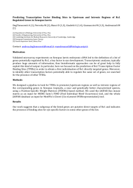
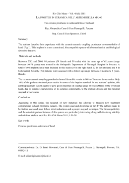
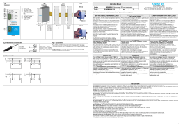
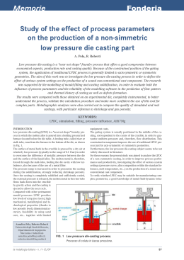
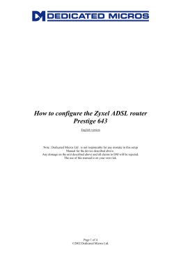
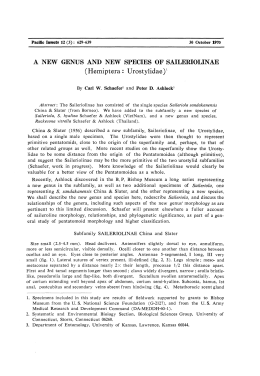
D811469 ver. 07 23-02-10 I QUADRO COMANDO GB CONTROL PANEL F CENTRALE DE COMMANDE D STEUERUNG E CUADRO DE MANDOS P QUADRO DE COMANDO 8 027908 279750 LEO-D-MA ISTRUZIONI D’USO E DI INSTALLAZIONE INSTALLATION AND USER’S MANUAL INSTRUCTIONS D’UTILISATION ET D’INSTALLATION INSTALLATIONS-UND GEBRAUCHSANLEITUNG INSTRUCCIONES DE USO Y DE INSTALACION INSTRUÇÕES DE USO E DE INSTALAÇÃO Via Lago di Vico, 44 36015 Schio (VI) Tel.naz. 0445 696511 Tel.int. +39 0445 696533 Fax 0445 696522 Internet: www.bft.it E-mail: [email protected] D811469_07 2 - LEO-D-MA D811469_07 MANUALE D’USO Nel ringraziarVi per la preferenza accordata a questo prodotto, la Ditta è certa che da esso otterrete le prestazioni necessarie al Vostro uso. Leggete attentamente l’opuscolo ”Libretto istruzioni” che lo accompagna in quanto esso fornisce importanti indicazioni riguardanti la sicurezza, l’installazione, l’uso e la manutenzione. Questo prodotto risponde alle norme riconosciute della tecnica e delle disposizioni relative alla sicurezza. Confermiamo che esso è conforme alle seguenti direttive europee: 2004/108/CEE, 2006/95/CEE, 2006/42/CEE e loro modifiche successive. 1) GENERALITÁ Il quadro comandi LEO-D-MA viene fornito dal costruttore con settaggio standard. Qualsiasi variazione, deve essere impostata mediante il programmatore a display incorporato o mediante programmatore palmare universale. La Centralina supporta completamente il protocollo EELINK compresa l’autoalimentazione del programmatore da centralina. è disponibile in due versioni: per installazione esterna, all’interno della scatola SD, o montata e precablata all’interno dell’attuatore. Le caratteristiche principali sono: - Rallentamento della velocità all’accostamento. - Regolazione elettronica della coppia. - Frenatura elettrodinamica regolabile. - Ingressi di fine-corsa chiusura / apertura - Ingressi separati per le sicurezze. - Ingresso orologio. - Ingressso collegamento protocollo seriale (opzionale). - Ricevitore radio incorporato 2) FUNZIONI PER L’INSTALLATORE: compilare la tabella con in parametri impostati al fine di facilitare future modifiche e manutenzioni. Tra parentesi quadre [ ] sono indicati i valori preimpostati. Menu parametri Mt. Pedonale [1m] _____ Tempo Chiusura Automatica [40s] _____ Encoder [2] _____ Coppia [55%] _____Impostabile solo con “Encoder”=2 Coppia apertura [75%] _____Impostabile solo con “Encoder”=1,0 Coppia chiusura [75%] _____Impostabile solo con “Encoder”=1,0 Coppia rallentamento [75%] _____Impostabile solo con “Encoder”=1,0 Freno [0] _____ Zona [0] _____ Spazio rallentamento [0] _____ MENU Logiche TCA [ON] _____ 3 Passi [OFF] _____ Blocca Impulsi [OFF] _____ Blocca Impulsi TCA [OFF] _____ Pre allarme [OFF] _____ Uomo Presente [OFF] _____ Chiusura rapida [OFF] _____ Fotocellule in apertura [OFF] _____ Master [OFF] _____ Test fotocellule (PHOT) [OFF] _____ Test costa sensibile (BAR) [OFF] _____ SCA/II°CH radio [ON] _____ Codice fisso [OFF] _____ Apprendimento radio [ON] _____ 3) DEMOLIZIONE Attenzione: Avvalersi esclusivamente di personale qualificato. L’eliminazione dei materiali va fatta rispettando le norme vigenti. Nel caso di demolizione, non esistono particolari pericoli o rischi derivanti dal prodotto stesso. È opportuno, in caso di recupero dei materiali, che vengano separati per tipologia (parti elettriche - rame - alluminio - plastica - ecc.). 4) SMANTELLAMENTO Attenzione: Avvalersi esclusivamente di personale qualificato. Nel caso la centralina venga smontata per essere poi rimontata in altro sito bisogna: • Togliere l’alimentazione e scollegare tutto l’impianto elettrico. • Nel caso alcuni componenti non possano essere rimossi o risultino danneggiati, provvedere alla loro sostituzione. AVVERTENZE Il buon funzionamento dell’operatore è garantito solo se vengono rispettate i dati riportati in questo manuale. La Ditta non risponde dei danni causati dall’inosservanza delle norme di installazione e delle indicazioni riportate in questo manuale. Le descrizioni e le illustrazioni del presente manuale non sono impegnative. Lasciando inalterate le caratteristiche essenziali del prodotto, la Ditta si riserva di apportare in qualunque momento le modifiche che essa ritiene convenienti per migliorare tecnicamente, costruttivamente e commercialmente il prodotto, senza impegnarsi ad aggiornare la presente pubblicazione. USER’S MANUAL Thank you for buying this product, our company is sure that you will be more than satisfied with the product’s performance. The product is supplied with a “Warnings” leaflet and an “Instruction booklet”. These should both be read carefully as they provide important information about safety, installation, operation and maintenance. This product complies with the recognised technical standards and safety regulations. We declare that this product is in conformity with the following European Directives: 2004/108/EEC and 2006/95/EEC, 2006/42/EEC (and subsequent amendments). 1) GENERAL OUTLINE The LEO-D-MA control panel is supplied by the manufacturer with standard setting. Any alteration must be set by means of the incorporated display programmer or by means of universal palmtop programmer. The Control unit completely supports the EELINK protocol, including the programmer self-supply from the control unit. It is available in two versions: one for external installation, inside the SD box, the other fitted and prewired inside the controller. Its main characteristics are: - Slow down of end-of-run speed. - Electronic torque setting - Adjustable electrodynamic braking - Closing / opening limit-switch inputs - Separate inputs for safety devices - Clock input - Serial protocol connection input (Option). - Incorporated radio receiver 2) FUNCTIONS FOR THE INSTALLER: Fill in the table with the parameters set, in order to facilitate future modifications and maintenance operations. The preset values are indicated between square brackets [ ]. parametER MENU Mt. Pedestrian Automatic Closing Time (TCA) Encoder Torque Opening torque Closing torque Slow-down torque Brake Zone Slow-down Distance [1m] [40s] [2] [55%] [75%] [75%] [75%] [0] [0] [0] _____ _____ _____ _____Can be set with “Encoder”=2 only. _____Can be set with “Encoder”=1,0 only. _____Can be set with “Encoder”=1,0 only. _____Can be set with “Encoder”=1,0 only. _____ _____ _____ ITALIANO ENGLISH Logic MENU TCA (TCA) [ON] _____ 3 Steps (3 Steps) [OFF] _____ Impulse locking [OFF] _____ TCA impulse locking [OFF] _____ Pre-alarm [OFF] _____ Hold-to-run [OFF] _____ Rapid closing [OFF] _____ Photocells on opening [OFF] _____ Master [OFF] _____ Loop [OFF] _____ Photocell test [OFF] _____ Electric edge test [OFF] _____ SCA/2nd radio channel [ON] _____ Fixed code [OFF] _____ Radio programming [ON] _____ 3) SCRAPPING Warning: This operation should only be carried out by qualified personnel. Materials must be disposed of in conformity with the current regulations. In case of scrapping, the automation devices do not entail any particular risks or danger. In case of materials to be recycled, these should be sorted out by type (electrical components, copper, aluminium, plastic etc.). 4) DISMANTLING Warning: This operation should only be carried out by qualified personnel. When the control unit is disassembled to be reassembled on another site, proceed as follows: • Disconnect the power supply and the entire electrical installation. • In the case where some of the components cannot be removed or are damaged, they must be replaced. WARNINGS Correct controller operation is only ensured when the data contained in the present manual are observed. The company is not to be held responsible for any damage resulting from failure to observe the installation standards and the instructions contained in the present manual. The descriptions and illustrations contained in the present manual are not binding. The Company reserves the right to make any alterations deemed appropriate for the technical, manufacturing and commercial improvement of the product, while leaving the essential product features unchanged, at any time and without undertaking to update the present publication. LEO-D-MA - 3 D811469_07 INSTALLATION MANUAL Thank you for buying this product, our company is sure that you will be more than satisfied with the product’s performance. The product is supplied with a “Warnings” leaflet and an “Instruction booklet”. These should both be read carefully as they provide important information about safety, installation, operation and maintenance. This product complies with the recognised technical standards and safety regulations. We declare that this product is in conformity with the following European Directives: 2004/108/EEC and 2006/95/EEC, 2006/42/EEC (and subsequent amendments). 1) GENERAL SAFETY WARNING! An incorrect installation or improper use of the product can cause damage to persons, animals or things. • The “Warnings” leaflet and “Instruction booklet” supplied with this product should be read carefully as they provide important information about safety, installation, use and maintenance. • Scrap packing materials (plastic, cardboard, polystyrene etc) according to the provisions set out by current standards. Keep nylon or polystyrene bags out of children’s reach. • Keep the instructions together with the technical brochure for future reference. • This product was exclusively designed and manufactured for the use specified in the present documentation. Any other use not specified in this documentation could damage the product and be dangerous. • The Company declines all responsibility for any consequences resulting from improper use of the product, or use which is different from that expected and specified in the present documentation. • Do not install the product in explosive atmosphere. • The construction components of this product must comply with the following European Directives: 2004/108/CEE, 2006/95/EEC, 2006/42/ EEC and subsequent amendments. As for all non-EEC countries, the above-mentioned standards as well as the current national standards should be respected in order to achieve a good safety level. • The Company declines all responsibility for any consequences resulting from failure to observe Good Technical Practice when constructing closing structures (door, gates etc.), as well as from any deformation which might occur during use. • The installation must comply with the provisions set out by the following European Directives: 2004/108/CEE, 2006/95/EEC, 2006/42/EEC and subsequent amendments. • Disconnect the electrical power supply before carrying out any work on the installation. Also disconnect any buffer batteries, if fitted. • Fit an omnipolar or magnetothermal switch on the mains power supply, having a contact opening distance equal to or greater than 3,5 mm. • Check that a differential switch with a 0.03A threshold is fitted just before the power supply mains. • Check that earthing is carried out correctly: connect all metal parts for closure (doors, gates etc.) and all system components provided with an earth terminal. • Fit all the safety devices (photocells, electric edges etc.) which are needed to protect the area from any danger caused by squashing, conveying and shearing. • Position at least one luminous signal indication device (blinker) where it can be easily seen, and fix a Warning sign to the structure. • The Company declines all responsibility with respect to the automation safety and correct operation when other manufacturers’ components are used. • Only use original parts for any maintenance or repair operation. • Do not modify the automation components, unless explicitly authorised by the company. • Instruct the product user about the control systems provided and the manual opening operation in case of emergency. • Do not allow persons or children to remain in the automation operation area. • Keep radio control or other control devices out of children’s reach, in order to avoid unintentional automation activation. • The user must avoid any attempt to carry out work or repair on the automation system, and always request the assistance of qualified personnel. • Anything which is not expressly provided for in the present instructions, is not allowed. • Installation must be carried out using the safety devices and controls prescribed by the EN 12978 Standard. • Check that the range of temperature indicated is compatible with the place of installation. • During installation, the power supply wires must be laid at an adequate distance from the motor, in order to prevent them from being affected by excessive temperature. • Power supply mains wires (230V) must be clearly separated from wires having very low safety voltage (SELV 24V), otherwise they must be provided with additional insulation, at least 1mm thick. ENGLISH • The cables entering the control unit must be kept away from heated parts (dissipator, braking resistor etc.). 2) GENERAL OUTLINE The LEO-D-MA control panel is supplied by the manufacturer with standard setting. Any alteration must be set by means of the incorporated display programmer or by means of universal palmtop programmer. The Control unit completely supports the EELINK protocol. It is available in two versions: one for external installation, inside the SD box, the other fitted and pre-wired inside the controller. Its main characteristics are: - Slow down of end-of-run speed. - Electronic torque setting - Adjustable electrodynamic braking - Closing / opening limit-switch inputs - Separate inputs for safety devices - Clock input - Serial protocol connection input (optional) - Incorporated radio receiver The board is provided with a terminal board which can be pulled out for easier maintenance or replacement. The board is supplied with a series of pre-wired jumpers to facilitate the installer’s work. The jumpers relate to the following terminals: 21-23, 21-24 and 21-30. If the above-mentioned terminals are in use, remove their respective jumpers. CHECK The control unit runs a check on the operating relays and safety mechanisms (photocells, sensor ridge, etc.) before performing opening and closing cycles. CONNECTION OF PHOTOCELLS AND SENSOR RIDGE: By convention, refer to a receiver (Rx- fig.7) with 5 terminals of which terminals 1 and 2 are for the 24V~ power supply, terminal 3 is shared, terminal 4 is the normally closed contact when at rest, terminal 5 is the normally open contact when at rest. The contact is not powered. LEGEND RX: photocell or infrared edge receiver. TX: photocell or infrared edge transmitter. Numerous combinations can be obtained between photocells and infrared edges; the most frequently used types of connections are illustrated in figures 7 to 14. - Fig.7 shows the connection of LEO-D-MA with 1 photocell and 1 infrared edge unchecked. In the logic menu, set the “test phot” and “test bar” functions to OFF. - Fig.8 shows the connection of LEO-D-MA with 1 photocell and 1 infrared edge checked. 8a : 1 photocell checked 8b : 1 infrared edge checked 8a+8b : 1 photocell + 1 edge checked In the logic menu, set the “test phot” and “test bar” functions to ON. - Fig.9 shows the connection of LEO-D-MA with 2 photocells and 2 infrared edges checked. 9a : 2 photocells checked 9b : 2 infrared edges checked 9a+9b : 2 photocells + 2 edges checked In the logic menu, set the “test phot” and “test bar” functions to ON. - Fig.10 shows the connection of LEO-D-MA with 3 photocells and 3 infrared edges checked. 10a : 3 photocells checked 10b : 3 infrared edges checked 10a+10b: 3 photocells + 3 edges checked In the logic menu, set the “test phot” and “test bar” functions to ON. - Fig.11 shows the connection of LEO-D-MA with 4 photocells and 1 infrared edge checked. 11a : 4 photocells checked 11a+11b : 4 photocells + 1 edge checked In the logic menu, set the “test phot” and “test bar” functions to ON. - Fig.12 shows the connection of LEO-D-MA with 1 photocell and 4 infrared edges checked. 11b : 4 infrared edges checked 11a+11b : 1 photocell + 4 edges checked In the logic menu, set the “test phot” and “test bar” functions to ON. - Fig.13 shows the connection of LEO-D-MA with 4 photocells and 2 infrared edges checked. In the logic menu, set the “test phot” and “test bar” functions to ON. - Fig.14 shows the connection of LEO-D-MA with 2 photocells and 4 infrared edges checked. In the logic menu, set the “test phot” and “test bar” functions to ON. LEO-D-MA - 13 INSTALLATION MANUAL 3) TECHNICAL SPECIFICATIONS Power supply:................................................................... 230V±10% 50Hz* Mains/low voltage insulation:......................................... > 2MOhm 500V Dielectric strength:........................... mains/low voltage 3750V~for 1 minute Motor output current:...................................................................... 1.5Amax Maximum motor power:..................................................................... 750 W Supply to accessories: ........................................24V~(1A max absorption) Gate-open warning light:.........................................................24V~3W max Blinker:.................................................................................230V 40W max Dimensions:................................................................................see figure 1 Fuses:.........................................................................................see figure 2 (* other voltages available on request) 4) TERMINAL BOARD CONNECTIONS (Fig.3) WARNING – During the wiring and installation operations, refer to the current standards as well as principles of good technical practice. The cables must be tied by additional fastening next to the terminals, by means of clips for example. All the operator wiring operations must be carried out by qualified personnel. The power supply cable must be stripped in order to allow the earth wire to be connected to the appropriate terminal, leaving the active wires as short as possible. This is to ensure that the earth wire is the last to stretch in the case where the cable fixing device becomes loose. JP1 1 2-3 JP2 4-5 6-7-8-9 JP3 10-11 12-13 10-14 15-16-17 18-19-20 JP5 JP8 21-22 21-23 21-24 21-25 21-26 21-27 21-28 21-29 21-30 21-31 JP9 32 33 38-39 GND terminal Single-phase mains supply 230V±10% 50Hz (2=N) (3=L) Blinker connection (mains voltage) 40W Max. Motor connection: 6 operation 1 + capacitor 7 common (blue) 8 operation 2 9 capacitor Output 24V~1A max – power supply for photocells or other devices. Gate-open warning light output (N.O. contact)/2nd radio channel 24V~ output for supply to photocell transmitters Connection of safety devices checked (see fig. 7 to 14) Connection of safety devices checked (see fig. 7 to 14) Encoder connection WARNING! The maximum length of the connection cable of the encoder should not exceed 3.00 mt. Open-Close button (N.O. Start), key selector. Block button (N.C. Stop). If not used, leave jumped. Photocell input (N.C.). If not used, leave jumped. Opening limit switch connection (N.C. SWO). If not used, leave jumped. Closing limit switch connection (N.C. SWC). If not used, leave jumped. Pedestrian button connection (N.O. Ped) Open-Button connection (N.O. Open) Close-Button connection (N.O. Close) Rubber edge connection (N.C.). If not used, leave jumped. Timer input connection (N.O.). If the contact is open the leaves close and the gate is ready for normal operation. If the contact is closed (N.C.), the leaves open and remain open until the contact is opened. Photocell check input (PHOT FAULT) (see fig. 7 to 14) Electric edge check input (EDGE FAULT) (see fig. 7 to 14) Antenna input for radio-receiver (38 signal - 39 braid). Cable RG58 5) PROGRAMMING The control panel provided with a microprocessor is supplied with function parameters preset by the manufacturer, suitable for standard installations. The predefined parameters can be altered by means of either the incorporated display programmer or universal palmtop programmer. In the case where programming is carried out by means of universal palmtop programmer, carefully read the instructions relating to universal palmtop programmer, and proceed in the following way. Connect the universal palmtop programmer to the control unit through the UNIFLAT accessory (See fig. 4). Enter the “CONTROL UNITS” menu, and the “PARAMETERS” submenu, then scroll the display screenfuls using the 14 - LEO-D-MA D811469_07 ENGLISH up/down arrows, and set the numerical values of the parameters listed below. For the function logics, refer to the “LOGIC” submenu. In the case where programming is carried out by means of the incorporated programmer, refer to Fig. A and B and to the “configuration” paragraph. 6) Configuration The display programmer is used to set all the LEO-D-MA control panel functions. The programmer is provided with three pushbuttons for menu scrolling and function parameter configurations (Fig. 2): + menu scrolling/value increment key - menu scrolling/value reduction key OK Enter (confirm) key The simultaneous pressure of the + and – keys is used to exit the active menu and move to the preceding menu. If the + and – keys are pressed simultaneously at the main menu level (parameters, logics, radio, language, autosetting), programming is exited and the display is switched off (the OK message is displayed). The modifications made are only set if the OK key is subsequently pressed. When the OK key is pressed for the first time, the programming mode is entered. The following pieces of information appear on the display at first: - Control unit Software version - Number of total manoeuvres carried out (the value is expressed in thousands, therefore the display constantly shows 0000 during the first thousand manoeuvres) - Number of manoeuvres carried out since the latest maintenance operation (the value is expressed in thousands, therefore the display constantly shows 0000 during the first thousand manoeuvres) - Number of memorised radio control devices. When the OK key is pressed during the initial presentation phase, the first menu (parameters) can be accessed directly. Here follows a list of the main menus and the respective submenus available. The predefined parameter is shown between square brackets [ 0 ]. The writing appearing on the display is indicated between round brackets. Refer to Figures A and B for the control unit configuration procedure. 6.1) Parameter Menu (PARAM) 1- Pedestrian opening (Mt. ped) [ 001.0 m ] Set the numerical value of the pedestrian opening from 10 cm (000.1) to 6m (006.0). 2- Automatic Closing Time (TCA) (tca) [ 40s ] Set the numerical value of the automatic closing time from 0 to 180 seconds. 3- Encoder (Encoder) [ 2 ] 0: operation without encoder (obligatory for ERGO, ICARO FM, D2 motors): timed slow-down, obstacle detection function not active. (The encoder can be disconnected). Manual setting of “opening torque”, “closing torque” and “slow-down torque” parameters. 1: operation with encoder: used as position sensor to aquire slow-down values. Obstacle detection function not active. Blocked gate detection. Manual setting of “opening torque”, “closing torque” and “slow-down torque” parameters. 2: Automatic operation with encoder: slow-down and obstacle detection by means of encoder. Possibility of using the “autosetting” function. Adjustment of sensitivity to obstacles (“torque” parameter). (default). WARNING: Check that the impact force value measured at the points established by the EN 12445 standard is lower than that specified in the EN 12453 standard. Incorrect sensitivity setting can cause injuries to persons or animals, or damage to things. 4- Torque (torque) [ 55% ]Can be set with “Encoder”=2 only. Set the motor torque value between 1% and 99%. This parameter indicates the sensitivity to obstacles. (Torque = 1 maximum sensitivity). Set the motor opening torque value between 1% and 99%. 5- Opening torque (open torque) [ 75% ] Can be set with “Encoder”=1,0 only. Set the motor opening torque value between 1% and 99%. 6- Closing torque (cls. torque) [ 75% ] Can be set with “Encoder”=1,0 only. Set the motor closing torque value between 1% and 99%. 7- Slow-down torque (slov torque) [ 75% ] Can be set with “Encoder”=1,0 only. (Advanced parameters ⇒ address 5) Set the motor opening and closing slow-down torque value between 1% and 99%. D811469_07 INSTALLATION MANUAL 8- Brake (Brake) [ 0% ] Set the required brake value between 0 and 99%, compatibly with the weight of the gate and the existing stresses. 9- Zone (zone) [ 0 ] (Advanced parameters ⇒ address 1) Set the zone number between a minimum value of 0 and a maximum value of 128. See paragraph 11 on “Serial connection”. 10-Slow-down Distance (Cm. rall) [ 000 ](Advanced parameters ⇒address 3) Set the required slow-down distance for opening and closing between 0 cm and 100 cm The 000 cm value does not carry out any slow-down. NOTE: If a slow-down distance value other than 000cm is set, after the first manoeuvre, power failure, the control panel carries out a complete manoeuvre at reduced speed, in order to learn the length of gate stroke. 6.2) Logic Menu (logic.) - TCA ( tca ) [ ON ] ON Activates automatic closing OFF Excludes automatic closing - 3 Steps (3 step) [ OFF ] ON Enables 3-step logic. A start impulse has the following effects: door closed:...............................................................................opens on opening: ............................. stops and enters TCA (if configured) door open:................................................................................ closes on closing:.......................................... stops and reverses movement after stopping:...........................................................................opens OFF Disables 3-step logic. - Opening Impulse lock (Ibl open) [ OFF ] ON The Start impulse has no effect during the opening phase. OFF The Start impulse becomes effective during the opening phase. - Impulse lock TCA (ibl TCA ) [ OFF ] ON The Start impulse has no effect during the TCA dwell period. OFF The Start impulse becomes effective during the TCA dwell period. - Pre alarm (pre-alarM) [ OFF ] ON The blinker comes on about 3 seconds before the motor starts. OFF The blinker comes on at the same time as the motor starts. - Hold-to-run (hold-to-run ) [ OFF ] ON Hold-to-run operation: the manoeuvre continues as long as the command key is kept pressed. OFF Impulse operation: one impulse opens the gate if closed, and closes it if open. - Rapid closing (fast cls ) [ OFF ] ON Closes the gate after photocell disengagement, before waiting for the end of the TCA (automatic closing time) set. OFF Command not entered. - Photocells on opening (photc. open) [ OFF ] ON In case of obscuring, this excludes photocell operation on opening. During the closing phase, it immediately reverses the motion. OFF In case of obscuring, the photocells are active both on opening and on closing. When a photocell is obscured on closing, it reverses the motion only after the photocell is disengaged. - Master/Slave (Master) [ OFF ] (Advanced logics ⇒ address 12) ON The control panel is set as Master in a centralised connection (see Paragraph 11). OFF The control panel is set as Slave in a centralised connection (see Paragraph 11). - Photocell test (test phot) [ OFF ] (Advanced logics ⇒ address 14) ON Activates photocell check (see fig. 7 to 14) OFF Deactivates photocell check - Electric edge test (test bar) [ OFF ] ON Activates electric edge check (see fig. 7 to 14) OFF Deactivates electric edge check - Gate-open or 2nd radio channel warning light (SCA 2ch) [ ON ] ON The output between terminals 12 and 13 is configured as Gate-open warning light, in this case the 2nd radio channel controls pedestrian opening. OFF The output between terminals 12 and 13 is configured as 2nd radio channel. - Fixed code (fixed code) [ OFF ] (Advanced logics ⇒ address 13) ON The receiver is configured for operation in fixed-code mode, see paragraph on “Radio Transmitter Cloning”. OFF The receiver is configured for operation in rolling-code mode, see paragraph on “Radio Transmitter Cloning”. - Radio transmitter programming (radio prog) [ ON ] (Advanced logics ⇒ address 15) ON This enables transmitter storage via radio: 1 – First press the hidden key (P1) and then the normal key (T1, T2, T3 or T4) of a transmitter already memorised in standard mode by means of the radio menu. 2 – Within 10s press the hidden key (P1) and the normal key (T1, T2, T3 or T4) of a transmitter to be memorised. ENGLISH The receiver exits the programming mode after 10s, other new transmitters can be entered before the end of this time. This mode does not require access to the control panel. OFF This disables transmitter storage via radio. The transmitters can only be memorised using the appropriate Radio menu. 6.3) Radio Menu (radio) - Add (add) Allows you to add one key of a radio control device to the receiver memory; after storage it displays a message showing the receiver number in the memory location (from 01 to 64). Add Start button (add start) associates the required key to Start command Add 2ch button (add 2ch) associates the required key to 2nd radio channel - Read (read) Checks one key of a receiver; if stored it displays a message showing the receiver number in the memory location (from 01 to 64), and the key number (T1, T2, T3 or T4). - Eliminate list (erease 64) WARNING! Completely removes all memorised radio control devices from the receiver memory. - Receiver code reading (RX code) This displays the code entered in the receiver. - W LINK (uk) ON = Enables remote programming of cards via a previously memorized W LINK remote control. It remains enabled for 3 minutes from the time the W LINK remote control is last pressed. Refer to the W LINK remote control’s manual for the mapping of the relevant keys. OFF = W LINK programming disabled. Consult paragraphs 7/8/9/10 for further information concerning the advanced functions of the Clonix incorporated receiver. 6.4) Language Menu (Language) Allows you to set the language on the display programmer. 5 languages are available: - ITALIAN (TA) - FRENCH (FRA) - GERMAN (DEU) - ENGLISH (ENG) - SPANISH (ESP) 6.5) MENU DEFAULT (DEFAULT) Restores the preset default values on the control unit. After restoring, a new autoset operation must be carried out. 6.6) DIAGNOSTICS AND MONITORING The display on the LEO-D-MA panel shows some useful information, both during normal operation and in the case of malfunctions. Diagnostics: In the case of malfunctions, the display shows a message indicating which device needs to be checked: STRT = STARTinput activation STOP = STOP input activation PHOT = PHOT input activation FLT = FAULT input activation for checked photocells SWO = input activation OPENING LIMIT SWITCH SWC = input activation CLOSING LIMIT SWITCH PED = input activation PEDESTRIAN OPEN = OPEN input activation CLS = CLOSE input activation BAR = input activation SAFETY EDGE TIME = TIMER input activation In the case where an obstacle is found, the LEO-D-MA panel stops the door and activates a reverse manoeuvre; at the same time the display shows the “BAR” message. Monitoring: During the opening and closing phases, the display shows four digits separated by a dot, for example 35.40. Figures are constantly updated during the manoeuvre and represent the instant torque reached by motor 1 (35) and threshold torque (opening, closing, slow-down) set in the parameter menu (40). LEO-D-MA - 15 INSTALLATION MANUAL These values allow the torque setting to be corrected. If the istant torque value reached during the manoeuvres turns out to be considerably close to the threshold value set in the parameter menu, future operation failures are likely to occur due to wearing or small door deformations. It is therefore advisable to check the maximum torque reached during some of the manoeuvres carried out in the course of installation, and if necessary set a value about 5-10 percent points higher in the parameter menu. 6.7) Autoset Menu (Autoset) Can be set with “Encoder”=2 only. Allows you to automatically set the following parameters: - Torque - Brake - Slow-down space (50 cm) WARNING!! Once the dist.sloud parameter has been edited, you will need to run an autoset cycle. WARNING!! The autoset operation is only to be carried out after checking the exact leaf (opening/closing) movement, and correct limit-switch activation. The autosetting operation is carried out from closing end-of-stroke devices. During this phase, the control panel performs 3 manoeuvres at different levels of opening/closing torque, slow-down torque, braking value. Moreover, during autosetting, the leaf may be stopped, due to the checks which are being carried out by the control panel. After this, if autosetting is successfully completed, the control unit automatically exits the (.... .... ....) phase, and displays the “OK” message which indicates correct autoset execution. If “KO” is displayed, this means that autoset was not correctly performed due to the presence of resistance points which did not allow the correct setting of the ideal operation values on the control unit. Proceed to find out whether there are any mechanical obstructions which might prevent regular leaf movement. Furthermore, the autoset function will not be successful, due to the activation of any of the inputs during the manoeuvre. WARNING! During autoset, the installer must check the movement of the automation and prevent persons or things from approaching or standing within the automation operating range. WARNING: Check that the impact force value measured at the points established by the EN 12445 standard is lower than that specified in the EN 12453 standard. Incorrect sensitivity setting can cause injuries to persons or animals, or damage to things. 6.8) Statistics Having connected the universal palmtop programmer to the control unit, enter the CONTROL UNIT / STATISTICS menu and scroll the screenful showing the statistical parameters: - Board microprocessor software version. - Number of cycles carried out. If motors are replaced, count the number of manoeuvres carried out up to that time. - Number of cycles carried out from the latest maintenance operation. It is automatically set to zero after each self-diagnosis or parameter writing. - Date of latest maintenance operation. To be updated manually from the appropriate menu “Update maintenance date”. - Installation description. 16 characters can be entered for installation identification. 7) INTEGRATED RECEIVER TECHNICAL SPECIFICATION Receiver output channels: - output channel 1, if activated, controls a START command. - output channel 2, if activated, controls the excitation of the 2nd radio channel relay for 1s. Transmitter versions which can be used: all Rolling Code transmitters compatible with . ANTENNA INSTALLATION Use an antenna tuned to 433MHz. For Antenna-Receiver connection, use RG8 coaxial cable. The presence of metallic masses next to the antenna can interfere with radio reception. In case of insufficient transmitter range, move the antenna to a more suitable position. 8) RECEIVER CONFIGURATION Cloning operations can be carried out with the special (universal palmtop programmer) programmer only. The on-board receiver combines characteristics of utmost safety in copying variable code (rolling code) coding with the convenience of carrying out transmitter “cloning” operations thanks to an exclusive system. 16 - LEO-D-MA D811469_07 ENGLISH Cloning a transmitter means creating a transmitter which can be automatically included within the list of the transmitters memorised in the receiver, either as an addition or as a replacement of a particular transmitter. Cloning by replacement is used to create a new transmitter which takes the place of the one previously memorised in the receiver; in this way a specific transmitter can be removed from the memory and will no longer be usable. Therefore it will be possible to remotely program a large number of additional transmitters or, for example, replacement transmitters for those which have been lost, without making changes directly to the receiver. When coding safety is not a decisive factor, the on-board receiver allows you to carry out fixed-code additional cloning which, although abandoning the variable code, provides a high number of coding combinations, therefore keeping it possible to “copy” any transmitter which has already been programmed. PROGRAMMING Transmitter storage can be carried out in manual mode or by means of the universal palmtop programmer which allows the complete installation database to be managed through the Eedbase software. In this second case, receiver programming takes place through the connection of universal palmtop programmer to the LEO-D-MA control panel, using the UNIFLAT and UNIDA accessories as indicated in Fig. 4. 9) MANUAL PROGRAMMING In the case of standard installations where advanced functions are not required, you can proceed to manual storage of the transmitters, making reference to fig. B for basic programming. - If you wish the transmitter to activate output 1 (START) by means of key1, key2, key3 or key4, enter the transmitter in menu “Start key”, as in fig. B. - If you wish the transmitter to activate output 2 (2nd radio channel relay) by means of key1, key2, key3 or key4, enter the transmitter in menu “2nd ch. key”, as in fig. B. Note: Hidden key P1 appears differently depending on the transmitter model. For transmitters with hidden key, press hidden key P1 (fig. B1). For transmitters without hidden key, the key P1 function corresponds to simultaneously pressing the 4 transmitter keys or, after opening the battery compartment, bridging the two P1 points by means of a screwdriver (fig. B2). IMPORTANT NOTE: ATTACH THE ADH ESIVE KEY LABEL TO THE FIRST MEMORISED TRANSMITTER (MASTER). In the case of manual programming, the first transmitter assigns the key code to the receiver; this code is necessary in order to carry out subsequent cloning of the radio transmitters. 10) RADIO-TRANSMITTER CLONING Rolling-code cloning / Fixed-code cloning Make reference to the universal palmtop programmer Instructions and the CLONIX Programming Guide. 10.1) ADVANCED PROGRAMMING: COLLECTIVE RECEIVERS Make reference to the universal palmtop programmer Instructions and the CLONIX Programming Guide. 11) SERIAL CONNECTION USING SCS1 BOARD (Fig.5) The LEO-D-MA control panel allows several automation units (SCS1) to be connected in a centralised way by means of appropriate serial inputs and outputs. This makes it possible to use one single command to open and close all the automation units connected. Following the diagram in Fig.5, proceed to connecting all the LEO-D-MA control panels, exclusively using a telephone-type line. Should a telephone cable with more than one pair be needed, it is indispensable to use wires from the same pair. The length of the telephone cable between one appliance and the next must not exceed 250 m. At this point, each of the LEO-D-MA control panels must be appropriately configured, by setting a MASTER unit first of all, which will have control over all the others, to be necessarily set as SLAVE (see logic menu). Also set the Zone number (see parameter menu) between 0 and 127. The zone number allows you to create groups of automation units, each one answering to the Zone Master unit. Each zone can only be assigned one Master unit, the Master unit in zone 0 also controls the Slave units in the other zones. 11.1) Opposite sliding leaves (Fig.6) By means of a serial connection, it is also possible to obtain centralised control of two opposite barriers/gates. In this case, the Master M1 control panel will simultaneously manage closing and opening for the Slave M2 control panel. D811469_07 INSTALLATION MANUAL ENGLISH SETTING REQUIRED FOR OPERATION: -MASTER board: zone=128, master=ON -SLAVE board: zone=128, master=OFF WIRING REQUIRED FOR OPERATION: -The MASTER and SLAVE control units are interconnected through the 4 wires (RX/TX) for the SCS1 interface boards; -All the activation controls, as well as the remote controls must refer to the MASTER board; -All the photocells (checked or unchecked) must be connected to the MASTER control panel; -The safety edges (checked or unchecked) of the MASTER leaf must be connected to the MASTER control unit; -The safety edges (checked or unchecked) of the SLAVE leaf must be connected to the SLAVE control unit. 12) SCRAPPING Warning: This operation should only be carried out by qualified personnel. Materials must be disposed of in conformity with the current regulations. In case of scrapping, the automation devices do not entail any particular risks or danger. In case of materials to be recycled, these should be sorted out by type (electrical components, copper, aluminium, plastic etc.). 13) DISMANTLING Warning: This operation should only be carried out by qualified personnel. When the control unit is disassembled to be reassembled on another site, proceed as follows: • Disconnect the power supply and the entire electrical installation. • In the case where some of the components cannot be removed or are damaged, they must be replaced. The descriptions and illustrations contained in the present manual are not binding. The Company reserves the right to make any alterations deemed appropriate for the technical, manufacturing and commercial improvement of the product, while leaving the essential product features unchanged, at any time and without undertaking to update the present publication. LEO-D-MA - 17 D811469_07 Fig. A ACCESS TO MENUS LEGENDA +/- Press the OK key OK OK BFT LEO-ma 1.0 0000 0000 00 8888 Control unit software version No. total manoeuvres (in thousands) No. manoeuvres since latest maintenance(in thousands) [ 00 ] /ON /OFF OK No. radio control devices memorised - + +/PARAM. OK Mt.ped OK Preset value Simultaneously press the + and - keys. Simultaneous pressure of the + and – keys allows you to exit the active menu and return to the preceding menu; if this takes place at the main menu level, programming is exited and the display switched off. The modifications made are only confirmed if the OK key is subsequently pressed. Parameter increment/reduction or ON/OFF commutation PRG OK! message (confirms modification made) Press OK key (Enter/confirm) PRG KO! message (value or function error) Menu scrolling (+ = preceding - = following) “Wait” message (enter value or function) OK [001.0] OK PRG OK [040] OK PRG OK [002] OK PRG OK [055] OK PRG Can be set with "Encoder"=2 only OK [075] OK PRG Can be set with "Encoder" = 0,1 only OK [075] OK PRG Can be set with "Encoder" = 0,1 only OK [075] OK PRG Can be set with "Encoder" = 0,1 only OK [000] OK PRG OK [000] OK PRG OK [000] OK PRG - + +/- TCA - + ENCOder - + torque - + open torque - + - + cls torque - + Slovd tor - + brake - + ZONE - + cm. slov +/LOGIC. OK TCA OK [on] ON OFF OK PRG OK [off] ON OFF OK PRG OK [off] ON OFF OK PRG OK [off] ON OFF OK PRG OK [off] ON OFF OK PRG OK [off] ON OFF OK PRG OK [off] ON OFF OK PRG OK [off] ON OFF OK PRG OK [off] ON OFF OK PRG OK [off] ON OFF OK PRG OK [off] ON OFF OK PRG OK [off] ON OFF OK PRG OK [on] ON OFF OK PRG OK [off] ON OFF OK PRG OK [on] ON OFF OK PRG - + +/- 3 step - + iblopen - + ibl tca - + PRE-ALarm - + - + hold-to-run - + fast cls - + photoc. open - + FOLLOWING MENUS FIG. B Master - + LOOP - + test phot - + test bar - + SCA 2ch - + fixed code - + radio prog 18 - LEO-D-MA D811469_07 Fig. B 1 RADIO P1 T1 T2 T1 T2 P1 PRECEDING MENUS FIG. A - + 3 2 P1 T1 T2 T3 T4 T1 T2 T3 T4 +/OK OK ADD start hidden button - + +/- 01 OK ADD 2ch END hidden button 01 - + release Press the required T (key) on radio control device – see Fig. B3 Press P1 (pushbutton) on radio control device. Release P1 on radio control device desired button release Press the required T (key) on radio control device – see Fig. B3 Release P1 on radio control device desired button 01 t1 Press the required T (key) on radio control device – see Fig. B3 OK READ Press P1 (pushbutton) on radio control device. - + - + OK ERASE 64 PRG. - + +/OK COD RX OK 1A9C 22FD OK 01 OK - + language OK ITA - + +/- FRA END OK OK - + - + DEU OK - + DEFAULT OK ENG PRG - + +/END OK esp OK - + OK AUTOset OK . . . . . . OK +/END LEO-D-MA - 19 D811469_07 Fig. 1 Fig. 2 100 194 F2: T 315 mA 236 F3:F 6,3A + OK SD LEO-D-MA Fig. 3 L 5 6 7 M 8 9 10 11 12 13 14 15 16 17 18 19 20 C GND 24 V~ VTX 24 V~ VTX N 4 2° CH.R./SCA 3 24 V~ 2 40W max. 1 JP3 JP2 24 V~ JP1 SCA 10 11 12 13 JP8 JP9 21 22 23 24 25 26 27 28 29 30 31 32 33 38 39 10 11 12 13 48 - LEO-D-MA D811469_07 Fig. 4 LEO-D-MA UNIFLAT UNIDA UNIPOWER UNIFLAT Contatti Contacts Contacts Kontakte Contactos Contatos UNIFLAT UNITRC UNIFLAT UNIMITTO UNITRC P1 Contatti Contacts Contacts Kontakte Contactos Contatos T1 T2 Led TRC 1-2 T1 2 T 3 T 4 T P1 P1 P1 P1 UNITRC UNIMITTO P1 2 1 Contatti Contacts Contacts Kontakte Contactos Contatos 3 4 1 3 2 4 LEO-D-MA - 49 D811469_07 Fig. 5 RX2 RX1 TX1 RX2 RX1 TX2 TX1 RX2 RX1 TX2 SCS1 SCS1 TX2 TX1 SCS1 Max. 250m SCS1 Fig. 6 RX1 (PHOT) CC2 TX1 (PHOT) TX2 (PHOT) RX2 (PHOT) LEO-MA-D M1 (MASTER) 50 - LEO-D-MA 21 22 23 24 25 26 27 28 29 30 31 32 33 TX SCS1 CC2 TX SWO SWC RX NC NC NC NC NC STOP RX LEO-MA-D M2 (SLAVE) COM CC1 FAULT CLOSE CC1 TIMER PHOT FAULT SWO SWC PED OPEN PHOT COM START STOP 21 22 23 24 25 26 27 28 29 30 31 32 33 NO NC NC NC NC NO NO NO NC NO zone=128 master=OFF M2 SLAVE M1 MASTER CC2 FAULT zone=128 master=ON CC1 RX RX TX TX SCS1 D811469_07 JP3 10 11 12 13 14 15 16 17 18 19 20 JP8 21 22 23 24 30 31 32 33 34 35 PHOT 14 1 10 2 PHOT FAULT BAR FAULT BAR PHOT K3" COM K3' STOP JP9 24 V~ VTX 24 V~ 24 V~ 24 V~ VTX Fig. 7 BAR TX1 RX1 1 11 14 1 2 10 10 2 3 21 TX1 RX1 1 11 2 10 3 21 4 4 24 5 30 5 JP3 10 11 12 13 14 15 16 17 18 19 20 a 1 10 2 30 31 32 33 34 35 b TX1 RX1 PHOT FAULT BAR FAULT BAR JP8 21 22 23 24 PHOT 14 STOP K3" COM K3' PHOT JP9 24 V~ VTX 24 V~ 24 V~ 24 V~ VTX Fig. 8 BAR 1 11 14 1 2 10 10 2 3 21 3 21 4 32 4 33 5 24 5 30 TX1 RX1 1 11 2 10 JP3 10 11 12 13 14 15 16 17 18 19 20 a b PHOT 14 1 10 2 TX1 JP8 21 22 23 24 RX1 PHOT FAULT BAR FAULT BAR K3" PHOT K3' STOP JP9 COM 24 V~ VTX 24 V~ 24 V~ 24 V~ VTX Fig. 9 30 31 32 33 34 35 BAR 1 11 14 1 2 10 10 2 TX1 RX1 1 10 2 TX2 RX2 11 2 10 3 3 14 1 4 21 4 21 5 24 5 30 1 11 14 1 1 11 2 10 10 2 2 10 3 TX2 RX2 3 4 32 4 33 5 21 5 21 LEO-D-MA - 51 JP3 10 11 12 13 14 15 16 17 18 19 20 a b PHOT 14 1 10 2 JP8 21 22 23 24 TX1 RX1 D811469_07 PHOT FAULT BAR FAULT BAR K3" PHOT K3' STOP JP9 COM 24 V~ VTX 24 V~ 24 V~ 24 V~ VTX Fig. 10 30 31 32 33 34 35 BAR 1 11 14 1 2 10 10 2 TX1 RX1 1 10 2 TX2 RX2 1 10 2 TX3 RX3 10 4 21 4 21 5 24 5 30 1 11 14 1 1 11 2 10 10 2 2 10 TX2 RX2 3 14 11 2 3 3 14 1 3 4 16 4 19 5 15 5 18 1 11 14 1 1 11 2 10 10 2 2 10 3 17 3 20 4 32 4 33 5 21 5 21 TX3 RX2 JP3 10 11 12 13 14 15 16 17 18 19 20 a b PHOT 14 1 10 2 TX1 RX1 1 10 2 TX2 RX2 11 14 1 2 10 10 2 1 10 2 14 1 10 2 52 - LEO-D-MA TX3, TX4 RX3 RX4 TX1 PHOT FAULT BAR FAULT RX1 1 11 2 10 3 21 4 23 4 33 5 24 5 30 1 11 2 10 3 14 30 31 32 33 34 35 BAR 1 3 14 JP8 21 22 23 24 BAR K3" PHOT K3' STOP JP9 COM 24 V~ VTX 24 V~ 24 V~ 24 V~ VTX Fig. 11 4 16 5 15 1 11 2 10 3 17 4 19 5 18 1 11 2 10 3 20 4 32 5 23 D811469_07 JP3 10 11 12 13 14 15 16 17 18 19 20 a b PHOT 14 1 10 2 JP8 21 22 23 24 TX1 RX1 PHOT FAULT BAR FAULT BAR K3" PHOT K3' STOP JP9 COM 24 V~ VTX 24 V~ 24 V~ 24 V~ VTX Fig. 12 30 31 32 33 34 35 BAR 1 11 14 1 2 10 10 2 3 21 3 4 32 4 21 5 24 5 30 1 11 2 10 14 1 10 2 TX1 RX1 TX1 RX1 1 11 2 10 3 14 1 10 2 14 1 10 2 TX1 RX1 TX1 RX1 4 16 5 15 1 11 2 10 3 17 4 19 5 18 1 11 2 10 3 20 4 33 5 21 JP3 10 11 12 13 14 15 16 17 18 19 20 a b PHOT 14 1 10 2 TX1 JP8 21 22 23 24 RX1 PHOT FAULT BAR FAULT BAR K3" PHOT K3' STOP JP9 COM 24 V~ VTX 24 V~ 24 V~ 24 V~ VTX Fig. 13 30 31 32 33 34 35 BAR 1 11 14 1 2 10 10 2 TX1 RX1 3 14 1 10 2 TX2 RX2 1 10 2 14 1 10 2 TX3 TX4 RX3 RX4 11 2 10 3 4 21 4 21 5 24 5 30 1 11 2 10 1 11 2 10 3 14 1 4 16 5 15 1 11 2 10 3 17 4 19 5 18 1 11 2 10 3 20 4 32 5 21 14 1 10 2 TX2 RX2 3 4 33 5 21 LEO-D-MA - 53 JP3 10 11 12 13 14 15 16 17 18 19 20 a b PHOT 14 1 10 2 TX1 JP8 21 22 23 24 RX1 1 11 2 10 D811469_07 PHOT FAULT BAR FAULT K3" BAR K3' PHOT JP9 COM 24 V~ VTX 24 V~ 24 V~ 24 V~ VTX Fig. 14 30 31 32 33 34 35 BAR 14 1 10 2 TX1 RX1 14 1 10 2 TX2 RX2 21 5 24 1 11 2 10 14 1 10 2 TX1 RX1 54 - LEO-D-MA 10 4 21 5 30 1 11 2 10 3 3 4 11 2 3 3 4 1 32 14 1 10 2 14 1 10 2 TX1 TX1 RX1 RX1 4 16 5 15 1 11 2 10 3 17 4 19 5 18 1 11 2 10 3 20 4 33 5 21
Scaricare