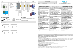
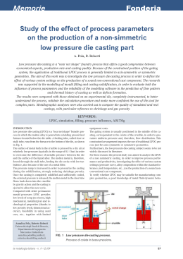
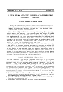
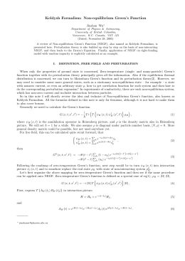
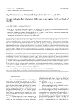
391 - 391 E
ITALIANO
AVVERTENZE PER L’INSTALLATORE
OBBLIGHI GENERALI PER LA SICUREZZA
ATTENZIONE! È importante per la sicurezza delle persone seguire attentamente tutta
l’istruzione. Una errata installazione o un errato uso del prodotto può portare a
gravi danni alle persone.
1. Leggere attentamente le istruzioni prima di iniziare l’installazione del prodotto.
2. I materiali dell’imballaggio (plastica, polistirolo, ecc.) non devono essere lasciati alla
portata dei bambini in quanto potenziali fonti di pericolo.
3. Conservare le istruzioni per riferimenti futuri.
4. Questo prodotto è stato progettato e costruito esclusivamente per l’utilizzo indicato in
questa documentazione. Qualsiasi altro utilizzo non espressamente indicato potrebbe
pregiudicare l’integrità del prodotto e/o rappresentare fonte di pericolo.
5. FAAC declina qualsiasi responsabilità derivata dall’uso improprio o diverso da quello
per cui l’automatismo è destinato.
6. Non installare l’apparecchio in atmosfera esplosiva: la presenza di gas o fumi infiammabili costituisce un grave pericolo per la sicurezza.
7. Gli elementi costruttivi meccanici devono essere in accordo con quanto stabilito
dalle Norme EN 12604 e EN 12605.
8. Per i Paesi extra-CEE, oltre ai riferimenti normativi nazionali, per ottenere un livello di
sicurezza adeguato, devono essere seguite le Norme sopra riportate.
9. FAAC non è responsabile dell’inosservanza della Buona Tecnica nella costruzione
delle chiusure da motorizzare, nonché delle deformazioni che dovessero intervenire
nell’utilizzo.
10. L’installazione deve essere effettuata nell’osservanza delle Norme EN 12453 e EN
12445. Il livello di sicurezza dell’automazione deve essere C+D.
11. Prima di effettuare qualsiasi intervento sull’impianto, togliere l’alimentazione elettrica
e scollegare le batterie.
12. Prevedere sulla rete di alimentazione dell’automazione un interruttore onnipolare con
distanza d’apertura dei contatti uguale o superiore a 3 mm. È consigliabile l’uso di
un magnetotermico da 6A con interruzione onnipolare.
13. Verificare che a monte dell’impianto vi sia un interruttore differenziale con soglia
da 0,03 A.
14. Verificare che l’impianto di terra sia realizzato a regola d’arte e collegarvi le parti
metalliche della chiusura.
15. L’automazione dispone di una sicurezza intrinseca antischiacciamento costituita
da un controllo di coppia. E’ comunque necessario verificarne la sogli di intervento
secondo quanto previsto dalle Norme indicate al punto 10.
16. I dispositivi di sicurezza (norma EN 12978) permettono di proteggere eventuali aree
di pericolo da Rischi meccanici di movimento, come ad Es. schiacciamento, convogliamento, cesoiamento.
17. Per ogni impianto è consigliato l’utilizzo di almeno una segnalazione luminosa nonché
di un cartello di segnalazione fissato adeguatamente sulla struttura dell’infisso, oltre
ai dispositivi citati al punto “16”.
18. FAAC declina ogni responsabilità ai fini della sicurezza e del buon funzionamento
dell’automazione, in caso vengano utilizzati componenti dell’impianto non di produzione FAAC.
19. Per la manutenzione utilizzare esclusivamente parti originali FAAC.
20. Non eseguire alcuna modifica sui componenti facenti parte del sistema d’automazione.
21. L’installatore deve fornire tutte le informazioni relative al funzionamento manuale
del sistema in caso di emergenza e consegnare all’Utente utilizzatore dell’impianto
il libretto d’avvertenze allegato al prodotto.
22. Non permettere ai bambini o persone di sostare nelle vicinanze del prodotto durante
il funzionamento.
23. L’applicazione non può essere utilizzata da bambini, da persone con ridotte capacità fisiche, mentali, sensoriali o da persone prive di esperienza o del necessario
addestramento.
24. Tenere fuori dalla portata dei bambini radiocomandi o qualsiasi altro datore di impulso,
per evitare che l’automazione possa essere azionata involontariamente.
25. Il transito tra le ante deve avvenire solo a cancello completamente aperto.
26. L’utente utilizzatore deve astenersi da qualsiasi tentativo di riparazione o d’intervento e deve rivolgersi solo ed esclusivamente a personale qualificato FAAC o centri
d’assistenza FAAC.
27. Tutto quello che non è previsto espressamente in queste istruzioni non è permesso.
ENGLISH
IMPORTANT NOTICE FOR THE INSTALLER
GENERAL SAFETY REGULATIONS
ATTENTION! To ensure the safety of people, it is important that you read all the following instructions. Incorrect installation or incorrect use of the product could
cause serious harm to people.
1. Carefully read the instructions before beginning to install the product.
2. Do not leave packing materials (plastic, polystyrene, etc.) within reach of children
as such materials are potential sources of danger.
3. Store these instructions for future reference.
4. This product was designed and built strictly for the use indicated in this documentation.
Any other use, not expressly indicated here, could compromise the good condition/
operation of the product and/or be a source of danger.
5. FAAC declines all liability caused by improper use or use other than that for which the
automated system was intended.
6. Do not install the equipment in an explosive atmosphere: the presence of inflammable
gas or fumes is a serious danger to safety.
7. The mechanical parts must conform to the provisions of Standards EN 12604 and
EN 12605.
8. For non-EU countries, to obtain an adequate level of safety, the Standards mentioned
above must be observed, in addition to national legal regulations.
9. FAAC is not responsible for failure to observe Good Technique in the construction
of the closing elements to be motorised, or for any deformation that may occur
during use.
10. The installation must conform to Standards EN 12453 and EN 12445. The safety level
of the automated system must be C+D.
11. Before attempting any job on the system, cut out electrical power and disconnect
the batteries.
12. The mains power supply of the automated system must be fitted with an all-pole
switch with contact opening distance of 3mm or greater. Use of a 6A thermal breaker
with all-pole circuit break is recommended.
13. Make sure that a differential switch with threshold of 0.03 A is fitted upstream of the
system.
14. Make sure that the earthing system is perfectly constructed, and connect metal parts
of the means of the closure to it.
15. The automated system is supplied with an intrinsic anti-crushing safety device consisting
of a torque control. Nevertheless, its tripping threshold must be checked as specified
in the Standards indicated at point 10.
16. The safety devices (EN 12978 standard) protect any danger areas against mechanical
movement Risks, such as crushing, dragging, and shearing.
17. Use of at least one indicator-light is recommended for every system, as well as a
warning sign adequately secured to the frame structure, in addition to the devices
mentioned at point “16”.
18. FAAC declines all liability as concerns safety and efficient operation of the automated
system, if system components not produced by FAAC are used.
19. For maintenance, strictly use original parts by FAAC.
20. Do not in any way modify the components of the automated system.
21. The installer shall supply all information concerning manual operation of the system
in case of an emergency, and shall hand over to the user the warnings handbook
supplied with the product.
22. Do not allow children or adults to stay near the product while it is operating.
23. The application cannot be used by children, by people with reduced physical, mental,
sensorial capacity, or by people without experience or the necessary training.
24. Keep remote controls or other pulse generators away from children, to prevent the
automated system from being activated involuntarily.
25. Transit through the leaves is allowed only when the gate is fully open.
26. The User must not in any way attempt to repair or to take direct action and must solely
contact qualified FAAC personnel or FAAC service centres.
27. Anything not expressly specified in these instructions is not permitted.
FRANÇAIS
CONSIGNES POUR L’INSTALLATEUR
RÈGLES DE SÉCURITÉ
ATTENTION! Il est important, pour la sécurité des personnes, de suivre à la lettre
toutes les instructions. Une installation erronée ou un usage erroné du produit
peut entraîner de graves conséquences pour les personnes.
1. Lire attentivement les instructions avant d’installer le produit.
2. Les matériaux d’emballage (matière plastique, polystyrène, etc.) ne doivent pas
être laissés à la portée des enfants car ils constituent des sources potentielles de
danger.
3. Conserver les instructions pour les références futures.
4. Ce produit a été conçu et construit exclusivement pour l’usage indiqué dans cette
documentation. Toute autre utilisation non expressément indiquée pourrait compromettre l’intégrité du produit et/ou représenter une source de danger.
5. FAAC décline toute responsabilité qui dériverait d’usage impropre ou différent de
celui auquel l’automatisme est destiné.
6. Ne pas installer l’appareil dans une atmosphère explosive: la présence de gaz ou de
fumées inflammables constitue un grave danger pour la sécurité.
7. Les composants mécaniques doivent répondre aux prescriptions des Normes EN
12604 et EN 12605.
8. Pour les Pays extra-CEE, l’obtention d’un niveau de sécurité approprié exige non
seulement le respect des normes nationales, mais également le respect des Normes
susmentionnées.
9. FAAC n’est pas responsable du non-respect de la Bonne Technique dans la construction des fermetures à motoriser, ni des déformations qui pourraient intervenir
lors de l’utilisation.
10. L’installation doit être effectuée conformément aux Normes EN 12453 et EN 12445. Le
niveau de sécurité de l’automatisme doit être C+D.
11. Couper l’alimentation électrique et déconnecter la batterie avant toute intervention
sur l’installation.
12. Prévoir, sur le secteur d’alimentation de l’automatisme, un interrupteur omnipolaire
avec une distance d’ouverture des contacts égale ou supérieure à 3 mm. On recommande d’utiliser un magnétothermique de 6A avec interruption omnipolaire.
13. Vérifier qu’il y ait, en amont de l’installation, un interrupteur différentiel avec un seuil
de 0,03 A.
14. Vérifier que la mise à terre est réalisée selon les règles de l’art et y connecter les pièces
métalliques de la fermeture.
15. L’automatisme dispose d’une sécurité intrinsèque anti-écrasement, formée d’un contrôle du couple. Il est toutefois nécessaire d’en vérifier le seuil d’intervention suivant
les prescriptions des Normes indiquées au point 10.
16. Les dispositifs de sécurité (norme EN 12978) permettent de protéger des zones éventuellement dangereuses contre les Risques mécaniques du mouvement, comme
l’écrasement, l’acheminement, le cisaillement.
17. On recommande que toute installation soit doté au moins d’une signalisation lumineuse, d’un panneau de signalisation fixé, de manière appropriée, sur la structure
de la fermeture, ainsi que des dispositifs cités au point “16”.
18. FAAC décline toute responsabilité quant à la sécurité et au bon fonctionnement de
l’automatisme si les composants utilisés dans l’installation n’appartiennent pas à la
production FAAC.
19. Utiliser exclusivement, pour l’entretien, des pièces FAAC originales.
20. Ne jamais modifier les composants faisant partie du système d’automatisme.
21. L’installateur doit fournir toutes les informations relatives au fonctionnement manuel du
système en cas d’urgence et remettre à l’Usager qui utilise l’installation les “Instructions
pour l’Usager” fournies avec le produit.
22. Interdire aux enfants ou aux tiers de stationner près du produit durant le fonctionnement.
23. Ne pas permettre aux enfants, aux personennes ayant des capacités physiques,
mentales et sensorielles limitées ou dépourvues de l’expérience ou de la formation
nécessaires d’utiliser l’application en question.
24. Eloigner de la portée des enfants les radiocommandes ou tout autre générateur
d’impulsions, pour éviter tout actionnement involontaire de l’automatisme.
25. Le transit entre les vantaux ne doit avoir lieu que lorsque le portail est complètement
ouvert.
26. L’utilisateur doit s’abstenir de toute tentative de réparation ou d’intervention et doit
s’adresser uniquement et exclusivement au personnel qualifié FAAC ou aux centres
d’assistance FAAC.
27. Tout ce qui n’est pas prévu expressément dans ces instructions est interdit.
ESPAÑOL
ADVERTENCIAS PARA EL INSTALADOR
REGLAS GENERALES PARA LA SEGURIDAD
ATENCION! Es sumamente importante para la seguridad de las personas seguir
atentamente las presentes instrucciones. Una instalación incorrecta o un uso
impropio del producto puede causar graves daños a las personas.
1. Lean detenidamente las instrucciones antes de instalar el producto.
2. Los materiales del embalaje (plástico, poliestireno, etc.) no deben dejarse al alcance
de los niños, ya que constituyen fuentes potenciales de peligro.
3. Guarden las instrucciones para futuras consultas.
391 - 391E
Page 5
Guide for the installer
IMPORTANT WARNINGS FOR THE INSTALLER
page.6
1. COMPONENTS (Fig. 1)
page.6
2. TECHNICAL SPECIFICATIONS
page.6
3. ELECTRICAL CONNECTIONS (Fig. 4)
page.6
4. INSTALLATION
page.6
4.1. PRELIMINARY CHECKS
page.6
4.2 INSTALLATION DIMENSIONS
page.7
4.3. INSTALLING THE OPERATOR
page.7
4.4. WIRING THE OPERATOR
page.7
4.5. POSITIONING THE MECHANICAL STOPS
page.7
5. AUTOMATED SYSTEM TEST
page.7
6. MANUAL MODE OPERATION
page.8
7. SPECIAL APPLICATIONS
page.8
8. MAINTENANCE
page.8
9. REPAIRS
page.8
10. ACCESSORIES
page.8
CE DECLARATION OF CONFORMITY
Manufacturer:
FAAC S.p.A.
Address:
Via Calari, 10 - 40069 - Zola Predosa - Bologna - ITALY
Declares that:
Operator mod. 391 - 391 E powered on 230V~
• is built to be integrated into a machine or to be assembled with other machinery to create a machine under the provisions of Directive
2006/42/EEC;
• conforms to the essential safety requirements of the following EEC directives:
• 2006/95/EC Low Voltage directive.
• 2004/108/EC Electromagnetic Compatibility directive.
• and also declares that it is prohibited to put into service the machinery until the machine in which it will be integrated or of which it will
become a component has been identified and declared as conforming to the conditions of Directive 2006/42/EEC and subsequent
modifications.
Bologna, December 30, 2009
Managing Director
A. Marcellan
Notes on reading the instruction
Read this installation manual to the full before you begin installing the product.
The symbol
indicates notes that are important for the safety of persons and for the good condition of the automated system.
The symbol
draws your attention to the notes on the characteristics and operation of the product.
ENGLISH
INDEX
Page 6
391 - 391E
Guide for the installer
Thank you for choosing our product. FAAC is sure that it will give you
all the performances you are looking for. All our products are the
result of a long experience in the field of the automated systems.
ENGLISH
In the middle of the manual you will find a detachable
booklet containing all the images for the installation.
The 391 automated system consists of a non-reversing electromechanical operator available in two versions:
• 391 E with built-in control unit
• 391 without control unit
The operator was designed for automating the opening of gates
with one or two leaves, with maximum length of 2.5m.
A handy, safe releases system, with personalised key, moves the
leaf in case of a power cut or fault.
The two articulated arms are designed for moving gates with very
large pilasters. The distance between the hinge and the gearmotor securing point can be up to 220 mm. Thanks to the special
geometry of the two arms, all possible shearing points have been
eliminated.
IMPORTANT WARNINGS FOR THE INSTALLER
• Carefully read the whole manual before beginning to install the
operator.
• Store the manual for future reference.
• The correct operation and the declared technical specifications
are only valid if the instructions given in this manual are strictly
observed and only FAAC accessories as well as safety device
are used.
• To guarantee an adequate level of safety of the automated
system, the use of a control unit with an adjustable electronic
clutch is necessary due to the lack of a mechanical clutch .
• The automated system was designed and built to control vehicle
access. Avoid any other use.
• The operator cannot be used to move safety exits or gates
installed on emergency routes (escape routes).
• Do not transit when the rod is moving.
• Anything not expressly specified in this manual is not permitted.
1. COMPONENTS (Fig. 1)
Pos.
/
0
1
2
3
4
5
6
7
8
Description
Gearmotor
Transformer
Control unit (for master motor only)
Release device
Receiver module (optional)
Mechanical stops
Transmission arm
Covering housing
Rear bracket
Lower housing
2. TECHNICAL SPECIFICATIONS
Model
391 E
391
Power supply
230 V~
/
Electric motor
24 V
Absorbed power
120 W
40 W
Max torque
250 N/m
Nominal torque
165 N/m
Max angular speed
13 °/sec
2.5 m
Max leaf /0
See graph fig. 2
Max leaf weight. 0
Use frequency at 20°C
80 cycles/day
Consecutive cycles at 20°C
30
Mximum continuous operating time
O.T. 17 min.
Protection Class
IP44
Operating ambient temperature
-20°C
+55°C
Noise level
<70 dB (A)
Operator weight
8.7 Kg
7 Kg
Dimensions
See fig. 3
/ For leaves with a length L>2m, an electric lock must be installed
to guarantee locking the leaf.
0 The weight P of the leaf is a function of the length L. Check if your
leaf is in the zone shown in the graph of fig. 2.
3. ELECTRICAL CONNECTIONS (Fig. 4)
Pos.
Description
/ Gearmotor 391 E
0 Gearmotor 391 /
1 Flashing lamp
2 Key-operated selector switch
3 Photocell transmitter
4 Photocell receiver
5 Electric lock 0
/Only for two leaf applications.
Cables section
3x2.5 mm2
2x2.5 mm2
2x1.5 mm2
2x0.5 mm2
2x0.5 mm2 (BUS)
2x0.5 mm2 (BUS)
2x1 mm2
0 Obligatory for leaf L>2m.
The lay-out below refers to an installation with two motors,
with all safety and signalling devices connected.
For two-motor applications, use a cable, type H05RN-F to
connect the MASTER and SLAVE operators.
4. INSTALLATION
4.1. PRELIMINARY CHECKS
To ensure a correctly operating automated system, the structure of
the gate to be moved must satisfy the following requirements:
• The mechanical construction elements must comply with the
provisions of the EN12604 and EN 12605 standards.
• leaf length must conform to the operator characteristics (see
paragraph 2)
• sturdy, rigid gate structure, suitable for the automated system
• smooth, uniform gate movement, without any friction and jamming during the entire opening;
• adequately sturdy hinges, in good condition
• an efficient earth socket for connection of the operator
We advise you to carry out the metalwork jobs if any, before
installing the automated system.
The condition of the gate structure directly influences the
reliability and safety of the automated system.
If the leaf to be motorised incorporates a door for the pedestrian
passage it is compulsory to add a safety switch on the door,
connected to the stop input, in order to inhibit the operation
of the automated system when the door is open.
The gearmotor cannot be used to move safety exits or gates
fitted on emergency routes (escape routes).
391 - 391E
Page 7
Guide for the installer
If dimension “A” permits opening values greater than the opening value selected, the value of dimension “B” can change
up to the maximum permissible opening value.
Make sure that the minimum dimension of 450mm in Fig. 5 is
observed.
When the operator has been installed, check if dimension “X”
in Fig. 5 is minimum 500 mm. If dimension “X” is less than
500 mm, run an impact test on the point indicated in Fig. 5,
as described in UNI EN12445 standard, and make sure that
the measured values conform to the specifications of UNI
EN 12453 standard.
If the thrust values are not within the values specified in UNI
EN12453 standard, the zone indicated in figure 5 MUST be
protected with a protective device conforming to the UNI
EN12978 standard.
The operator was studied and made to be secured vertically
(Fig. 6). The operator cannot be installed in other positions.
4.3. INSTALLING THE OPERATOR
When you have established dimensions “A” and “B”, you can install
the operator as follows:
1. Loosen by about 1/2 turn the four securing screws of the upper housing (Fig. 7 ref. /) and withdraw the housing. Set the
operator for manual operation, see paragraph 6.
2. Establish the height of the operator, bearing in mind that:
• the securing bracket of the curved arm must be in a zone
where it can be secured to the gate leaf (Fig. 8)
• the minimum off ground height of the operator must permit
securing the curved arm and positioning the lower housing (at
least 85 mm, see fig. 8).
• the lower edge of the rear bracket must be aligned with respect to the upper edge of the front bracket (Fig. 9).
3. Secure the rear bracket in the position you had established,
using four M8 screws. As you secure the bracket, respect the
lay-out in Fig. 10 and check, using a level, if the bracket is
horizontal.
To improve water tightness, the external housing covers the
securing bracket - this prevents the bracket from being
directly welded on the pilaster.
The rear bracket must be secured on an as smooth as possible
surface. For masonry pilasters, a counter-plate for walling is
available as an accessory.
4. Position the operator on the bracket you have just secured,
using two M8x100 screws and the relevant nuts - supplied
(Fig. 11).
5. Set the operator for manual operation, see paragraph 6.
6. Install the straight arm (Fig. 12) with the supplied screw.
7. Assemble the rest of the arm as illustrated in Fig. 13.
For correct operation, tighten the two securing screws (Fig.
13 ref. /) and then loosen them by about 1/2 turn to enable
rotation without any friction on the arms.
8. Align the arms you have just assembled, pushing in the central
zone until they stop, see Fig. 14 ref. /.
There are two stops on the curved arm to facilitate the aligning operation.
9. Rest the front bracket on the leaf, Fig. 14 ref. 0.
10. Move back the front bracket by about 20 mm and mark the
securing holes, Fig. 14 ref. 1.
11. Secure the bracket in the established position using two M8
screws.
We advise you to secure the bracket with the screws, and
not weld it to the leaf, in order not to rule out future adjustments.
12. Move the bracket by hand and - with the leaf in closing position
- make sure that the two arms do not impact each other, as
shown in Fig. 14 ref. 0.
13. Take the operator back to the work position - see paragraph
6.
4.4. WIRING THE OPERATOR
When you have finished securing the operator, you can wire it.
There are three holes in the lower part of the operator. They should
be used for positioning the cable grippers, for routing the power
cables, for connecting accessories and, if necessary, for connecting
the second motor.
1. Install all the three supplied cable grippers with the securing
nuts (Fig. 15).
Always use the largest cable gripper (Fig. 15 ref. /)
If the other two cable grippers are not used, they must be
closed, using the supplied plugs (Fig. 15 ref. 0). Fit the plastic
plug in the cable routing hole and close the cable gripper
until it is tight.
2. Connect the power cable, as shown in Fig. 16. The earthing
wire must also be connected. Make sure that the power cable
wires are correctly fitted in the ‘comb’ which restrains them
Fig. 16.
If the protective fuse has to be replaced, use a fuse with the
following characteristics: 5x20 2A 450V.
3. Wire all the accessories and safety devices, observing the
relevant instructions.
4.5. POSITIONING THE MECHANICAL STOPS
The 391 operator is supplied standard with opening and closing
mechanical stops. This is to facilitate the installation operations
because there is no need to construct the mechanical stop elements. The mechanical stops should be fitted in the lower part of
the operator, coupled to a toothed sector. Installation procedure
for the stops:
OPENING MECHANICAL STOP
1. Set the operator for manual operation, see paragraph 6.
2. Manually move the leaf to its opening position.
3. Take the mechanical stop as close as possible to the straight
arm and fasten the two securing screws.
Make sure that the toothed sector is coupled correctly.
CLOSING MECHANICAL STOP
Use the closing mechanical stop only in the absence of a
mechanical stop on the closing leaf.
The closing mechanical stop does not guarantee locking the
leaf in case of burglary.
1. Set the operator for manual operation, see paragraph 6.
2. Manually move the leaf to its closed position.
3. Take the mechanical stop as close as possible to the straight
arm and fasten the two securing screws.
Make sure that the toothed sector is coupled correctly.
5. AUTOMATED SYSTEM TEST
• When you have made all the necessary electrical connections,
power up the system and program the control unit according to
your requirements.
• Run the test for the automation and for all the connected accessories, taking great care when checking the safety devices.
• Re-locate the upper covering housing, tighten the securing screws
and position the four covering plugs fig. 18 ref. /.
• Position the lower housing as shown in fig. 18 ref. 0.
• Hand the “User’s Guide” booklet to the customer and describe
its correct operation and use.
Point out, to the end user, any residual risks present in the
installation.
ENGLISH
4.2 INSTALLATION DIMENSIONS
Procedure for finding the securing position of the operator, using
Fig. 5 to help you:
• measure dimension “A” of the gate and trace a horizontal line
on the graph on the measured value, this line to cross the whole
graph.
• you will obtain the maximum permissible angular opening according to dimension “A” of the graph.
• select the opening range you require
• select dimension “B” so that it intersects the horizontal line (dimension “A”) inside the required opening range.
Page 8
391 - 391E
Guide for the installer
6. MANUAL MODE OPERATION
If the operator has to be manually activated due to a power cut
or to an operator fault, proceed as follows:
1. Cut power to the system with the differential switch.
2. Lift the protective plug from the lock, fig. 19 ref. /.
3. Fit the key and turn it anti-clockwise until it stops, fig. 19 ref.
0.
4. Turn the release knob clockwise until it stops, fig.19 ref. 1.
5. Move the leaf by hand.
ENGLISH
PROCEDURE FOR RESTORING NORMAL OPERATION:
1. Make sure that the system is not powered.
2. Position the leaf to its closing position.
3. Turn the release knob anti-clockwise until it stops, then turn the
key clockwise until it stops and remove it.
4. Check if the release device has been correctly engaged, by
trying to move the leaf by hand. The leaf must be locked and
it must not be possible to move it by hand.
5. Re-position the lock covering plug.
6. Restore power to the system and command an opening
cycle.
The operator may not correctly execute the decelerations
on the first cycle. Wait for the end of the cycle and give
another opening command.
7. SPECIAL APPLICATIONS
Applications other than those in this manual are EXPRESSLY PROHIBITED
8. MAINTENANCE
To ensure correct long-term operation and a constant level of safety, we advise you to generally control the system every 6 months.
In the “User’s Guide” booklet, there is a form for recording jobs.
9. REPAIRS
The User must not in any way attempt to repair or to take direct
action and must solely contact qualified FAAC personnel or FAAC
service centres.
10. ACCESSORIES
For accessories, see the FAAC catalogue.
391 - 391E
Pag. 1
Immagini - Images - Images - Imágenes - Bilder - Afbeeldingen
Fig. 01
Fig. 02
Fig. 03
Fig. 04
Fig. 06
Fig. 05
Fig. 07
Pag. 2
391 - 391E
Immagini - Images - Images - Imágenes - Bilder - Afbeeldingen
Fig. 08
Fig. 09
Fig. 10
Fig. 11
Fig. 12
Fig. 13
Fig. 14
Fig. 15
391 - 391E
Guida per l’utente – User’s guide
Instructions pour l’utilisateur – Guía para el usuario
Anweisungen für den Benutzer - Gebruikersgids
391 - 391E
Page 3
Instructions for use
Read the instructions carefully before using the product and
store them for future use
DESCRIPTION
The 391 automated system is ideal for controlling vehicle access
areas in residential environments.
For details on sliding gate behaviour in different function logics,
consult the installation Technician.
Automated systems include safety devices (photocells) that prevent the gate from closing when there is an obstacle in the area
they protect.
The system ensures mechanical locking when the motor is not operating and, therefore, for gates of less than 2m in length, installing
a lock is unnecessary.
Manual opening is, therefore, only possible by using the release
system.
The built-in control unit has an adjustable electronic clutch enabling
safe use of the automated system.
A handy manual release facility makes it possible to move the gate
in the event of a power cut or fault.
The warning-light indicates that the gate is currently moving.
MANUAL MODE OPERATION
If the operator has to be manually activated due to a power cut
or to an operator fault, proceed as follows:
1. Cut power to the system with the differential switch.
2. Lift the protective plug from the lock, fig. 1 ref. /.
3. Fit the key and turn it anti-clockwise until it stops, fig. 1 ref. 0.
4. Turn the release knob clockwise until it stops, fig. 1 ref. 1.
5. Move the leaf by hand.
Fig. 01
RESTORING NORMAL OPERATION MODE
Procedure to return the operator to normal work condition:
1. Make sure that the system is not powered.
2. Position the leaf about halfway of the memory-stored opening.
3. Turn the release knob anti-clockwise until it stops, then turn the
key clockwise until it stops and remove it.
4. Check if the release device has been correctly engaged, by
trying to move the leaf by hand. The leaf must be locked and
it must not be possible to move it by hand.
5. Re-position the lock covering plug.
6. Restore power to the system and command an opening
cycle.
MAINTENANCE
To ensure correct long-term operation and a constant level of safety, we advise you to generally control the system every 6 months.
In the “User’s Guide” booklet, there is a form for recording jobs.
REPAIRS
The User must not in any way attempt to repair or to take direct
action and must solely contact qualified FAAC personnel or FAAC
service centres.
ENGLISH
GENERAL SAFETY REGULATIONS
If correctly installed and used, the 391 automated system will ensure a high degree of safety. Some simple rules on behaviour can
prevent accidental trouble:
• Do not stand near the automated system, and do not allow children, persons or things to do so, especially when it is operating.
• Keep radio-controls, or any other pulse generators that could
involuntarily activate the automated system, well away from
children.
• Do not allow children to play with the automated system.
• Do not willingly obstruct gate movement.
• Prevent any branches or shrubs from interfering with gate movement.
• Keep the indicator-lights efficient and easy to see.
• Do not attempt to activate the gate by hand unless you have
released it.
• In the event of malfunctions, release the gate to allow access and
wait for qualified technical personnel to do the necessary work.
• When you have set manual operation mode, cut power to the
system before restoring normal operation.
• Do not in any way modify the components of the automated
system.
• The User must not in any way attempt to repair or to take direct
action and must solely contact qualified FAAC personnel or FAAC
service centres.
• At least every six months: arrange a check by qualified personnel
of the automated system, safety devices and earth connection.
Registro di manutenzione - Maintenance register - Registre d’enttretien
Registro de mantenimeinto - Wartungsprogramm - Onderhoudregister
REGISTRO DI MANUTENZIONE / MAINTENANCE REGISTER / REGISTRE D’ENTTRETIEN / REGISTRO DE MANTENIMIENTO / WARTUNGSPROGRAMM / ONDERHOUDREGISTER
Dati impianto / System data / données de l’installation / Datos equipo / Daten der Anlage / Gegevens
installatie
Installatore / Installer / Installateur / Installador / Monteur / installateur
Cliente / Customer / Client / Cliente / Kunde / Klant
Tipo impianto / Type of system / Type d’installation / Tipo de equipo /
Art der Anlage / Type installatie
Matricola / Serial No. / N° de série / N° de serie / Seriennummer / Seriennummer
Data installazione / Installation date / Date d’installation / Fecha de
installatión / Installationsdatum / datum installatie
Attivazione / Start-up / Activation / Activación / Inbetriebnahme /
Activering
Configurazione impianto / System configuration / Confijguration de l’installation / Configuración del equipo / Konfiguration der Anlage / Configuratie installatie
COMPONENTE / PART / COMPOSANT / COMPONENTE MODELLO / MODEL / MODÈLE / MODE/ BAUTEIL / ONDEREEL
LO / MEDELL / MODEL
MATRICOLA / SERIAL NUMBER / N° DE
SERIE / N° DE SERIE / SERIENNUMMER /
SERIENUMMER
Operatore / Operator / Opérateur / Operador / Antrieb
/ Aandrijving
Dispositivo di sicurezza 1 / Safety device 1 / dispositif
de sécurité 1 / Dispositivo de seguridad 1 / Scherheltsvorrichtung 1 / Velligheldsvoorziening 1
Dispositivo di sicurezza 2 / Safety device 2 / dispositif
de sécurité 2 / Dispositivo de seguridad 2 / Scherheltsvorrichtung 1 / Velligheldsvoorziening 2
Coppia di fotocellule 1 / Pair of photocells 1 / Paire de
photocellules 1 / Par de fotocélulas 1 / Fotozellenpaar
1 / Paar fotocellen 1
Coppia di fotocellule 2 / Pair of photocells 2 / Paire de
photocellules 2 / Par de fotocélulas 2 / Fotozellenpaar
2 / Paar fotocellen 2
Dispositivo di comando 1 / Control device 1 / Dispositif
de commande 1 / Dispositivi de mando 1 / Schaltvorrichtung 1 / Bedieningsvoorziening 1
Dispositivo di comando 2 / Control device 2 / Dispositif
de commande 2 / Dispositivi de mando 2 / Schaltvorrichtung 2 / Bedieningsvoorziening 2
Radiocomando / Radio control / Radiocommande /
Radiomando / Funksteuerung / Afstandsbediening
Lampeggiante / Flashing lamp / Lampe clignotante /
Destellador / Blinkleuchte / Signaallamp
Indicazione dei rischi residui e dell’uso improprio prevedibile / Indication of residual risks and of foreseeable improper use / Indication des risques résiduels et de l’usage impropre prévisible / Indicación de los riesgos residuos y del uso impropio previsible /
Angabe der Restrisiken und der voraussehbaren unsachgemäßen Anwendung / Aanduiding van de restrisico’s en van voorzienbaar
oneigenlijk gebruik
Registro di manutenzione - Maintenance register - Registre d’enttretien
Registro de mantenimeinto - Wartungsprogramm - Onderhoudregister
Nr
1
2
3
4
5
6
7
8
9
10
Data / Date
/ Date /
Descrizione intervento / Job description / Description de
Fecha /
l’intervention / Descripción de la intervención / BeschreiDatum /
bung der Arbeiten / Beschrijving ingreep
Datum
Firme / Signatures / Signatures / Firma / Unterschrift /
Handtekeningen
Tecnico / Technicia
Technicien / Técnico
Techniker / Technicus
Cliente / Customer
Client / Cliente
Kunde / Klant
Tecnico / Technicia
Technicien / Técnico
Techniker / Technicus
Cliente / Customer
Client / Cliente
Kunde / Klant
Tecnico / Technicia
Technicien / Técnico
Techniker / Technicus
Cliente / Customer
Client / Cliente
Kunde / Klant
Tecnico / Technicia
Technicien / Técnico
Techniker / Technicus
Cliente / Customer
Client / Cliente
Kunde / Klant
Tecnico / Technicia
Technicien / Técnico
Techniker / Technicus
Cliente / Customer
Client / Cliente
Kunde / Klant
Tecnico / Technicia
Technicien / Técnico
Techniker / Technicus
Cliente / Customer
Client / Cliente
Kunde / Klant
Tecnico / Technicia
Technicien / Técnico
Techniker / Technicus
Cliente / Customer
Client / Cliente
Kunde / Klant
Tecnico / Technicia
Technicien / Técnico
Techniker / Technicus
Cliente / Customer
Client / Cliente
Kunde / Klant
Tecnico / Technicia
Technicien / Técnico
Techniker / Technicus
Cliente / Customer
Client / Cliente
Kunde / Klant
Tecnico / Technicia
Technicien / Técnico
Techniker / Technicus
Cliente / Customer
Client / Cliente
Kunde / Klant
Page 10
391 - 391E
Note - Notes - Note - Notas - Anmerkung - Opmerkingen
391 - 391E
Page 11
Note - Notes - Note - Notas - Anmerkung - Opmerkingen
Le descrizioni e le illustrazioni del presente manuale non sono impegnative. La FAAC si riserva il diritto, lasciando inalterate le caratteristiche essenziali dell’apparecchiatura, di apportare in qualunque momento e senza impegnarsi
ad aggiornare la presente pubblicazione, le modifiche che essa ritiene convenienti per miglioramenti tecnici o per
qualsiasi altra esigenza di carattere costruttivo o commerciale.
The descriptions and illustrations contained in the present manual are not binding. FAAC reserves the right, whilst
leaving the main features of the equipments unaltered, to undertake any modifications it holds necessary for either
technical or commercial reasons, at any time and without revising the present publication.
Les descriptions et les illustrations du présent manuel sont fournies à titre indicatif. FAAC se réserve le droit d’apporter à
tout moment les modifications qu’elle jugera utiles sur ce produit tout en conservant les caractéristiques essentielles,
sans devoir pour autant mettre à jour cette publication.
Die Beschreibungen und Abbildungen in vorliegendem Handbuch sind unverbindlich. FAAC behält sich das Recht
vor, ohne die wesentlichen Eigenschaften dieses Gerätes zu verändern und ohne Verbindlichkeiten in Bezug auf die
Neufassung der vorliegenden Anleitungen, technisch bzw. konstruktiv/kommerziell bedingte Verbesserungen vorzunehmen.
Las descripciones y las ilustraciones de este manual no comportan compromiso alguno. FAAC se reserva el derecho,
dejando inmutadas las características esenciales de los aparatos, de aportar, en cualquier momento y sin comprometerse a poner al día la presente publicación, todas las modificaciones que considere oportunas para el perfeccionamiento técnico o para cualquier otro tipo de exigencia de carácter constructivo o comercial.
De beschrijvingen in deze handleiding zijn niet bindend. FAAC behoudt zich het recht voor op elk willekeurig moment de
veranderingen aan te brengen die het bedrijf nuttig acht met het oog op technische verbeteringen of alle mogelijke
andere productie- of commerciële eisen, waarbij de fundamentele eigenschappen van de apparaat gehandhaafd
blijven, zonder zich daardoor te verplichten deze publicatie bij te werken.
FAAC S.p.A.
Via Calari, 10
40069 Zola Predosa (BO) - ITALIA
Tel. 0039.051.61724 - Fax. 0039.051.758518
www.faac.it
www.faacgroup.com
00058I0594 Rev.3
391 - 391E
Pag. 3
Immagini - Images - Images - Imágenes - Bilder - Afbeeldingen
Fig. 16
Fig. 17
Fig. 18
Fig. 19
Page 4
391 - 391E
Note - Notes - Note - Notas - Anmerkung - Opmerkingen
Le descrizioni e le illustrazioni del presente manuale non sono impegnative. La FAAC si riserva il diritto, lasciando inalterate le caratteristiche essenziali dell’apparecchiatura, di apportare in qualunque momento e senza impegnarsi
ad aggiornare la presente pubblicazione, le modifiche che essa ritiene convenienti per miglioramenti tecnici o per
qualsiasi altra esigenza di carattere costruttivo o commerciale.
The descriptions and illustrations contained in the present manual are not binding. FAAC reserves the right, whilst
leaving the main features of the equipments unaltered, to undertake any modifications it holds necessary for either
technical or commercial reasons, at any time and without revising the present publication.
Les descriptions et les illustrations du présent manuel sont fournies à titre indicatif. FAAC se réserve le droit d’apporter à
tout moment les modifications qu’elle jugera utiles sur ce produit tout en conservant les caractéristiques essentielles,
sans devoir pour autant mettre à jour cette publication.
Die Beschreibungen und Abbildungen in vorliegendem Handbuch sind unverbindlich. FAAC behält sich das Recht
vor, ohne die wesentlichen Eigenschaften dieses Gerätes zu verändern und ohne Verbindlichkeiten in Bezug auf die
Neufassung der vorliegenden Anleitungen, technisch bzw. konstruktiv/kommerziell bedingte Verbesserungen vorzunehmen.
Las descripciones y las ilustraciones de este manual no comportan compromiso alguno. FAAC se reserva el derecho,
dejando inmutadas las características esenciales de los aparatos, de aportar, en cualquier momento y sin comprometerse a poner al día la presente publicación, todas las modificaciones que considere oportunas para el perfeccionamiento técnico o para cualquier otro tipo de exigencia de carácter constructivo o comercial.
De beschrijvingen in deze handleiding zijn niet bindend. FAAC behoudt zich het recht voor op elk willekeurig moment de
veranderingen aan te brengen die het bedrijf nuttig acht met het oog op technische verbeteringen of alle mogelijke
andere productie- of commerciële eisen, waarbij de fundamentele eigenschappen van de apparaat gehandhaafd
blijven, zonder zich daardoor te verplichten deze publicatie bij te werken.
FAAC S.p.A.
Via Calari, 10
40069 Zola Predosa (BO) - ITALIA
Tel. 0039.051.61724 - Fax. 0039.051.758518
www.faac.it
www.faacgroup.com
00058I0594 Rev.3
Scaricare