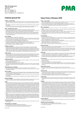
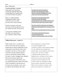
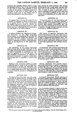
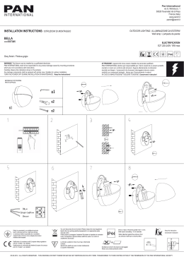
INTERNATIONAL J/24 CLASS ASSOCIATION
IN CASO DI ERRORI DI TRADUZIONE O CONTESTAZIONI
REGOLAMENTO FA FEDE IL TESTO ORIGINALE IN INGLESE
NELL’INTERPRETAZIONE
DI
QUESTO
TABLE OF CONTENTS
INDICE DEI CONTENUTI
CLASS RULES
REGOLAMENTO DI CLASSE
3
1 OBJECTIVES OF THE CLASS RULES
1 OBIETTIVI DEL REGOLAMENTO DI CLASSE
3
2 ADMINISTRATION
2 AMMINISTRAZIONE
3
3 CONSTRUCTION AND MEASUREMENT
3 COSTRUZIONE E STAZZA
5
4 SAFETY RULES WHEN RACING
4 NORME DI SICUREZZA IN REGATA
15
5 CREW
5 EQUIPAGGIO
15
6 OPTIONAL EQUIPMENT
6 ATTREZZATURE FACOLTATIVE
16
7 PROHIBITIONS
7 PROIBIZIONI
17
8 RESTRICTIONS WHEN RACING
8 RESTRIZIONI IN REGATA
18
PLAN A
PIANO A
DECK LAYOUT
INTERIOR LAYOUT
CORRECTOR WEIGHT PLACEMENT
DISPOSIZIONE DELLA COPERTA
DISPOSIZIONE INTERNA
POSIZIONAMENTO DEI PESI CORRETTORI
20
21
24
PLAN B
MEASUREMENT POINTS AND INSIGNIA
PIANO B
PUNTI DI STAZZA E LOGO
25
PLAN C
KEEL PLAN
PIANO C
SEZIONE DELLA CHIGLIA
26
PLAN D
RUDDER PLAN
PIANO D
SEZIONE DEL TIMONE
27
APPENDIX A – SAIL MEASUREMENT
APPENDICE A – STAZZA DELLE VELE
28
2
Effective 1 aprile, 2013
Effective 1 aprile, 2013
INTERNATIONAL J/24 CLASS ASSOCIATION
IN CASO DI ERRORI DI TRADUZIONE O CONTESTAZIONI
REGOLAMENTO FA FEDE IL TESTO ORIGINALE IN INGLESE
NELL’INTERPRETAZIONE
DI
QUESTO
CLASS RULES
REGOLAMENTO DI CLASSE
As approved by the ISAF, effective 1 aprile 2013
Come approvato dall’ISAF, in vigore dal 1 aprile 2013
1 OBJECTIVES OF THE CLASS RULES
1.1 The J/24 is a one design class created to fulfill the
diverse needs of recreational sailors such as cruising, one
design racing, day sailing and handicap racing. These rules
are intended to preserve important design characteristics:
ease of handling, low cost of ownership, safety, comfort,
and the one design nature of the boat.
1.3 All yachts shall comply with official Plans A, B, C & D,
building specifications and the class rules. No
alterations or modifications are permitted unless explicitly
stated in the current rules.
1.4 Alterations or modifications to official Plans A, B, C & D,
and class rules shall only be permitted with the joint
approval of the copyright holder, the International J/24
Class Association (IJCA) and the ISAF.
1 OBIETTIVI DEL REGOLAMENTO DI CLASSE
1.1 La J/24 è una classe di monotipi creata per soddisfare
diverse esigenze dei diportisti come la crociera, la regata tra
monotipi, la navigazione diurna e la regata a compensi.
Queste regole hanno lo scopo di conservare le importanti
caratteristiche del progetto: facilità di manovra, bassi costi per
i proprietari, sicurezza, confort e caratteristiche di
imbarcazione monotipo.
1.2 Fatta eccezione ove sono specificatamente permessi
cambiamenti, le imbarcazioni di questa classe devono essere
uguali per quanto riguarda lo scafo, la coperta, la chiglia, la
costruzione del timone e dell'albero, il peso, la distribuzione
dei pesi, il piano velico e le dotazioni.
1.3 Tutte le imbarcazioni devono essere conformi alle Tavole
A, B, C e D, alle specifiche di costruzione e al Regolamento di
Classe. Non sono permesse alterazioni o modifiche se non
esplicitamente stabilito nel Regolamento in vigore.
1.4 Alterazioni o modifiche delle Tavole ufficiali A, B, C e D e
delle Regole della Classe potranno essere autorizzate soltanto
con l'approvazione congiunta di chi detiene il diritto d'autore (J
Boat Inc.), della Classe Internazionale IJCA e dell’ISAF.
2 ADMINISTRATION
2.1 Authority: The international authority for the class
shall be the ISAF, which shall cooperate with the
International J/24 Class Association on all matters regarding
these rules. Interpretations of these rules shall be made by
the ISAF, which in coming to its decision may consult the
International J/24 Class Association and the copyright
holder.
2.2 Language The official language for the class shall be
English. The word “shall” is mandatory. The word “may” is
permissive. In the event of dispute over class rule
interpretation, the English text shall prevail.
2 AMMINISTRAZIONE
2.1 Autorità: l’autorità internazionale della classe deve
essere l’ISAF, che deve collaborare con l'Associazione di Classe
Internazionale J/24 per quanto riguarda tutti gli argomenti che
compongono questo Regolamento. Le interpretazioni di questo
Regolamento devono essere date dall’ISAF che, nel
determinare le sue decisioni, può consultare l'Associazione
della Classe Internazionale J/24 ed il titolare del progetto.
2.2 Lingua: la lingua ufficiale della classe deve essere
l'inglese. La voce "deve" é ingiuntiva. La voce “può” é
facoltativa. In caso di controversia sull'interpretazione di una
Regola di Classe deve prevalere il testo inglese.
2.3 Builders J/24s shall be built only by builders licensed
to do so under the copyright of J Boats, Inc., (557 Thames
St., P.O. Box 90, Newport, RI 02840) and shall comply to
the building specifications detailed by the copyright holder.
2.3 Costruttori: il J/24 deve essere costruito soltanto dai
costruttori licenziatari, nell'osservanza dei diritti d'autore della
J Boats Inc. (557 Thames St., P.O. Box 90, Newport, RI
02840) e deve essere conforme alle specifiche di costruzione
con i particolari specificati dal titolare del progetto.
2.3.1 Licenza di costruzione: Le domande per le licenze di
costruzione devono essere inoltrate alla J Boats Inc. la quale
deve richiedere che l'Autorità Nazionale del paese interessato
attesti il suo appoggio alla richiesta.
2.4 Tassa di Costruzione: la tassa di costruzione deve
essere pagata alla J Boats Inc. quando viene iniziato lo
stampaggio dello scafo.
2.5 Certificato di Stazza
2.5.1 Il Certificato di Stazza deve includere tutte le
informazioni contenute nelle Parti A,B,C e D del J/24 Class
Measurement Form
1.2 Except where variations are specifically permitted,
yachts of this class shall be alike in hull, deck,
keel, rudder and mast construction, weight and weight
distribution, sail plan and equipment.
2.3.1 Building License Applications for building licenses
shall be made to J Boats, Inc., who shall request that the
national authority of the country concerned indicates its
support for the applicant.
2.4 International Class Fee The International Class Fee
shall be payable to J Boats, Inc. when the moulding of the
hull commences.
2.5 Measurement Certificate
2.5.1 The Measurement Certificate shall include all of the
information contained in Parts A, B, C and D of the J/24
Class Measurement Form.
3
Effective 1 aprile, 2013
Effective 1 aprile, 2013
INTERNATIONAL J/24 CLASS ASSOCIATION
IN CASO DI ERRORI DI TRADUZIONE O CONTESTAZIONI
REGOLAMENTO FA FEDE IL TESTO ORIGINALE IN INGLESE
2.5.2 A boat’s sail number shall be her hull number unless
otherwise prescribed by the owner’s national authority.
When a boat is chartered or loaned the boat’s sail number
may be that of the member who chartered or borrowed the
boat.
2.5.3 No yacht shall race unless a current valid
Measurement Certificate has been issued by the
International J/24 Class Association. This certificate will be
in addition to any certificates required by the owner’s
national authority.
2.5.4 Change of ownership shall invalidate the
Measurement Certificate and shall require a new
Measurement Certificate.
2.5.5 Any alteration to the hull or alteration to or
replacement of the keel, rudder, and spars invalidates the
Measurement Certificate until re-measured. A major repair
to any of the foregoing or replacement of an item of
equipment may also invalidate the Measurement Certificate.
2.5.6 It is the responsibility of an owner to ensure that the
yacht complies at all times with the current class rules and
that a copy of the Measurement Certificate and the
Inventory of Required and Optional Equipment (Rule 3.7.3)
are kept aboard the yacht.
2.5.7 No yacht shall race unless the owner(s) and
helmsman(men) are full members of an NJCA or the IJCA.
2.5.8 No yacht shall race without a current J/24 Class
Association membership sticker placed on the outer face of
the transom near the upper starboard corner.
2.6 Advertising
2.6.1 Pursuant to ISAF Regulation 20.5.2 Advertising is
permitted as provided in ISAF Regulation 20.
2.7 Measurement
2.7.1 Yachts shall only be measured by a measurer
recognized by the International J/24 Class Association. This
applies to all references of “J/24 Measurer” or “J/24 Class
Measurer” in the Class Rules.
2.7.2 A measurer shall not measure a yacht, spars, sails, or
equipment owned or built by himself, or in which he is an
interested party or has a financial involvement.
2.7.3 The method of measurement shall be in accordance
with the IJCA Measurement Manual.
2.7.4 Tolerances in measurement in the rules and
measurement plans are to provide for minor building errors
or age distortion.
2.7.5 The measurer shall report on the measurement form
anything which is considered to be a departure from the
intended nature and design of the yacht, or to be against
the general interest of the Class. A measurement certificate
may be refused even if the specific requirements of the
rules are satisfied.
2.8 Licensed Builder
2.8.1 The builder shall weigh the keel and record the
weight of the keel before the assembly with the hull on Part
B of the Measurement Form.
NELL’INTERPRETAZIONE
DI
QUESTO
2.5.2. Il numero velico di una imbarcazione deve essere il
numero di matricola dello scafo se non diversamente prescritto
dall'Autorità Nazionale del proprietario. Una barca a noleggio o
in prestito può esporre il numero velico di chi noleggia o
prende in prestito l’imbarcazione.
2.5.3 Nessuna imbarcazione può partecipare a regate se non
è stato rilasciato un valido Certificato di Stazza da parte della
Classe Internazionale J/24. Questo certificato sarà in aggiunta
a qualsiasi certificato rilasciato da parte dell’Autorità Nazionale
del proprietario.
2.5.4 Il cambio di proprietà invalida il Certificato di Stazza e
rende necessario un nuovo Certificato di Stazza.
2.5.5 Qualsiasi alterazione dello scafo o della coperta, o la
sostituzione della chiglia, del timone e delle antenne invalida il
Certificato di Stazza fino a una nuova Stazzatura. Un lavoro di
riparazione importante ad una delle parti sopraddette o la
sostituzione di un particolare dell’equipaggiamento, può anche
invalidare il Certificato di Stazza.
2.5.6 E' responsabilità del proprietario assicurarsi che
l’imbarcazione sia conforme in ogni momento al Regolamento
di Classe in vigore e che sia tenuta a bordo una copia del
Certificato di Stazza e della lista dell'equipaggiamento
obbligatorio e facoltativo (regola 3.7.3.)
2.5.7 Nessuna imbarcazione può partecipare a regate se il
proprietario (o i proprietari) ed il timoniere (o i timonieri) non
sono a pieno titolo soci di un'Associazione di Classe Nazionale
o Internazionale.
2.5.8 Nessuna imbarcazione può partecipare a regate senza
esibire l’adesivo dell'Associazione di Classe per l'anno in corso
posto in prossimità dell'angolo alto a dritta della parte esterna
dello specchio di poppa.
2.6 Pubblicità
2.6.1 Conformemente al regolamento ISAF 20.5.2 la
pubblicità è consentita, come previsto nella Regola ISAF 20.
2.7 Stazza
2.7.1 Le imbarcazioni devono essere stazzate solo da uno
stazzatore riconosciuto dalla Classe Internazionale J/24. Ciò si
intende ogni qual volta in questo Regolamento di Classe viene
menzionato lo “Stazzatore J/24” o lo “Stazzatore di Classe
J/24”.
2.7.2 Uno stazzatore non deve stazzare un’imbarcazione,
antenne, vele o dotazioni di sua proprietà o da lui stesso
costruiti, o nei quali egli sia parte interessata od abbia un
interesse economico.
2.7.3 Il metodo di misurazione deve esser in accordo con il
Manuale di Stazza IJCA
2.7.4 Le tolleranze di stazza contenute nel regolamento e
nelle Tavole di misurazione devono esser applicate per piccoli
errori di costruzione o distorsioni dovute all’età
2.7.5 Lo stazzatore deve riportare nel modulo di stazza
qualsiasi cosa sia considerata uno scostamento dalle
caratteristiche e dal progetto stabilito per l’imbarcazione, o che
sia contro gli interessi generali della Classe. Un certificato di
stazza può essere rifiutato anche se sono state osservate le
specifiche prescrizioni del Regolamento.
2.8 Modalità di Stazza
2.8.1 Il costruttore deve pesare la chiglia e registrarne il peso,
prima dell’assemblaggio con lo scafo, sulla Parte B del
Measurement Form.
4
Effective 1 aprile, 2013
Effective 1 aprile, 2013
INTERNATIONAL J/24 CLASS ASSOCIATION
IN CASO DI ERRORI DI TRADUZIONE O CONTESTAZIONI
REGOLAMENTO FA FEDE IL TESTO ORIGINALE IN INGLESE
NELL’INTERPRETAZIONE
DI
QUESTO
2.8.2 The boat in ‘Builder’s Weight’ condition shall be not
less than 1190 kg or more than 1250 kg on certified scales.
This weight shall include hull, keel, rudder and tiller with
fittings, deck and all specified mouldings and structures and
all fixed fittings as detailed on Plan A.
Additionally, distinctively marked, permanently fixed and
completely capsulated corrector weights not exceeding 30
kg. in total weight complying with rule 3.7.2b), b) i), and c),
shall be used when required to meet the Builder’s minimum
weight. Builder’s Weight excludes all spars, standing rigging,
running rigging, portable equipment and hardware.
The builder shall weigh the boat and record the weight as
Item 2b on Part B of the Measurement Form, and if
corrector weights are required, as Item 3 on Part B of the
Measurement Form. The builder shall complete Part C of the
measurement form, and deliver the completed form (Parts B
and C) to the owner of each new yacht. The builder shall
also deliver one copy each to the IJCA and the Copyright
Holder, and retain one file copy.
2.8.2 L’imbarcazione nelle condizioni del “peso del
costruttore” non deve pesare meno di 1190 kg o più di 1250
kg, rilevato con una bilancia certificata. Tale peso deve
includere scafo, bulbo, timone e barra con relativi accessori,
coperta e tutte le parti stampate, le strutture, gli accessori
fissi, come specificato nel Piano A.
Correttori di peso aggiuntivi, marcati in modo evidente, non
removibili, completamente rivestiti, non dovranno superare
complessivamente i 30 kg come prescritto dalla Regola
3.7.2b), b) i), e c), dovranno essere usati, quando richiesto,
per raggiungere il peso minimo del costruttore. Dal peso del
costruttore sono esclusi tutte le antenne, le manovre fisse, le
manovre correnti, gli equipaggiamenti ed attrezzi.
Il costruttore deve pesare la barca e registrarne il peso, come
descritto nel Punto 2b della Parte B del Certificato di Stazza, e
registrare eventuali correttori di peso, come al Punto 3 della
Parte B del Certificato di Stazza.
Il costruttore deve completare la Parte C del Certificatoo di
Stazza, e consegnare il modulo completo (Parte B e C) al
proprietario di ogni nuova imbarcazione. Il costruttore dovrà
inoltre consegnarne una copia alla IJCA ed al titolare del
progetto, e conservarne una copia.
3 CONSTRUCTION AND MEASUREMENT
3.1 General
3.1.1 The hull, keel stub, keel, deck, rudder, sail plan, and
basic interior layout and fittings shall conform to the
building specifications, Class rules and official Plans A, B, C
& D.
3. COSTRUZIONE E STAZZA
3.1 Generalità
3.1.1 Scafo, attacco del bulbo, bulbo, coperta, timone, piano
velico, attrezzature e sistemazioni di base degli interni devono
conformarsi alle specifiche di costruzione, al Regolamento
della Classe ed alle Tavole ufficiali A, B, C e D.
3.1.2 Major repairs requiring major rebuilding or
replacement of a gelcoat surface must have the written
approval of a J/24 Class Measurer. Documentation of the
work involved must be submitted when the yacht is
presented for re-measurement, Rule 2.5.5.
3.1.2 Riparazioni di rilevante importanza, che comportano
ricostruzioni rilevanti o la sostituzione della superficie in
gelcoat devono essere approvate per iscritto da uno stazzatore
della classe J24. La documentazione dei lavori effettuati deve
essere presentata al momento in cui l’imbarcazione viene
ristazzata. Regola 2.5.5.
3.1.3 Ogni alterazione, asserita o sospetta, della
conformazione dello scafo, della coperta, della chiglia o del
timone di una imbarcazione, per le quali non sono state
stabilite descrizioni precise nel Regolamento e nelle Specifiche
di costruzione, oppure in seguito a protesta riguardante le
stesse, deve essere raffrontata, da parte di uno stazzatore
della Classe J/24, con una campionatura ottenuta da altre 10
imbarcazioni.
L’imbarcazione contestata deve essere accettata se non vi è
prova che sia stata alterata e se le sue dimensioni sono uguali
o comprese fra le dimensioni massime e minime rilevate sulle
altre 10 imbarcazioni a campione.
Se vi é prova che sono state apportate alterazioni, o se le
dimensioni sono maggiori o minori di quelle massime e minime
3.1.3 Any alleged or suspected alteration to the
configuration of the hull, deck, keel or rudder of a yacht for
which specific descriptions are not stated in the rules or
specifications, or following a protest concerning the same,
shall be compared by a J/24 Class Measurer to a sample of
10 other yachts.
The disputed yacht shall be accepted if she does not show
any evidence of having been altered and if she has
dimensions equal to, or between, those of the maximum
and minimum dimensions obtained from the sample of 10
yachts.
If there is evidence of any alterations having been made or
if the dimensions are greater or less than those of the
maximum or minimum obtained from the sample of 10
yachts,
the matter shall be referred to the protest committee for
action.
3.1.4 Required and optional equipment shall be functional
for its intended use.
3.2 Hull
3.2.1 The hull, deck and interior shall be moulded in glass
reinforced plastics to the building specification of lamination
in moulds licensed by J Boats, Inc. and approved by the
ISAF and the IJCA. No yacht shall be deemed a J/24 until it
ricavate dalla campionatura ottenuta da altre 10 imbarcazioni,
la questione deve essere segnalata al Comitato proteste per
provvedimenti.
3.1.4 Gli equipaggiamenti obbligatori e opzionali devono
essere funzionali per il loro uso previsto.
3.2 Scafo
3.2.1 Lo scafo, la coperta e gli interni devono essere stampati
in vetroresina, secondo le specifiche di costruzione della
laminazione, negli stampi forniti dalla J Boats Inc. e approvati
dall’ISAF e dall' IJCA. Nessuna imbarcazione dovrà essere
5
Effective 1 aprile, 2013
Effective 1 aprile, 2013
INTERNATIONAL J/24 CLASS ASSOCIATION
IN CASO DI ERRORI DI TRADUZIONE O CONTESTAZIONI
REGOLAMENTO FA FEDE IL TESTO ORIGINALE IN INGLESE
has been completed with a building number assigned by
JBoats, Inc. moulded into the transom. Hollows and
indentations on the hull exterior as supplied by the licensed
builder may be filled in order to achieve a fair surface.
Although the removal of gel coat is not permitted, surface
abrasion as required for over coating is permitted.
3.2.2 The keel stub may be faired to maximise keel position
to rule 3.3.3 with provisions of the rules 3.1.2 and 3.2.8 a
and b.
3.2.3 The cockpit, deck and interior bulkheads shall
conform to the details of official Plan A. The main
companionway cover shall be supplied by a licensed builder
or licensed supplier.
3.2.4 The cabin moulding on the starboard side aft of the
main bulkhead may be fitted with a basin, sink or stove.
3.2.5 The deck shall be fitted with two stanchions on each
side, port and starboard as detailed in Plan A.
Taut lifelines of wire not less than 4mm diameter shall be
attached to the pulpit and pushpit and pass through the
stanchions.
The height of the lifelines above the sheerline when
measured vertically shall be not less than 500mm. Where
second lifelines are fitted, they shall be of wire not less than
3mm diameter, attached to the pulpit and pushpit. When
lifelines are secured by lanyards, the lanyards shall be of
synthetic rope with an exposed length of not more than 100
mm.
The stanchions shall not extend outboard of the sheer in
plan.
3.2.6 The chain plates shall be fixed to the aft side of the
forward bulkhead by the licensed builder.
3.2.7 The minimum moulded radius of the corner
intersecting the hull and the transom is 2mm. Fairing
material may be added to reduce the corner radius to 2mm,
but this fairing material shall not extend aft of, nor more
than 10mm forward of the vertical plane of the moulded
transom.
3.2.8 Prohibitions. The following are not permitted:
a) coring, drilling out, rebuilding, replacement of
materials, grinding or relocating standard equipment in
any way to reduce weight, to improve moments of
inertia, or to change standard shapes;
b) reshaping of the hull profiles or contours;
c) windows or skin fittings other than one each for depth
meter and/or a knot meter/ log and/or two for a marine
toilet;
d) anything that is considered to unnecessarily increase
the ‘Basic Yacht Weighed Dry’, Rule 3.7.1(4).
3.3 Keel
3.3.1 The keel shall be of moulded lead to the building
specifications and cast in a mould licensed by J Boats, Inc.
and approved by ISAF and the IJCA.
NELL’INTERPRETAZIONE
DI
QUESTO
considerata un J/24 fino al momento in cui non sarà dotata di
un numero di costruzione assegnato dalla J Boats Inc.,
stampato sulla superficie esterna dello specchio di poppa.
Imperfezioni e sbavature della parte esterna dello scafo
esistenti alla consegna da parte del costruttore autorizzato
possono essere eliminate per ottenere una superficie levigata.
Sebbene sia proibito rimuovere il gelcoat, una leggera
abrasivatura per predisporre lo stesso all'applicazione di
materiali ricoprenti è permessa.
3.2.2 L’ attacco del bulbo potrà essere modificato per
massimizzare la posizione del bulbo in accordo alla regola
3.3.3. secondo le prescrizioni delle regole 3.1.2, 3.2.8 a e b.
3.2.3 Il pozzetto, la coperta e le paratie interne devono essere
conformi ai particolari del Piano ufficiale A. Il portello
dell'ingresso principale dovrà essere fornito da un costruttore
licenziatario o da un fornitore licenziatario.
3.2.4 Alla parte stampata della cabina, sul lato dritto a
poppavia della paratia principale, può essere fissato un lavello,
un recipiente o fornello per la cottura.
3.2.5 La coperta su ciascun lato, a sinistra e a dritta, deve
essere munita di due candelieri, come specificato nel Piano A.
Ai pulpiti di prua e di poppa devono essere fissate le draglie in
cavo metallico del diametro non inferiore a 4 mm, che devono
passare attraverso i candelieri.
L'altezza delle draglie, misurata verticalmente al di sopra
dell'insellatura, non deve essere minore di 500 mm. Ove
vengono sistemati, parallelamente, altre draglie, esse devono
essere in cavo metallico del diametro non inferiore a 3 mm. e
fissate ai pulpiti di prua e di poppa. Quando le draglie sono
fissate mediante legature, queste devono essere di cavo
sintetico e la lunghezza libera di attacco fra la draglia ed il
candeliere non deve essere più lunga di 100 mm.
I candelieri non devono sporgere all'esterno della proiezione
verticale della linea di insellatura.
3.2.6 Le lande devono essere fissate dal costruttore
licenziatario, alla faccia poppiera della paratia prodiera.
3.2.7 Il raggio minimo allo stampaggio, all'intersezione dello
specchio di poppa con la rimanente parte dello scafo è 2 mm.
Del materiale di riporto può essere aggiunto per ridurre il
raggio dello specchio di poppa a 2 mm, ma questo materiale
non deve estendersi né più dietro né più avanti di 10 mm della
parte verticale dello specchio di poppa.
3.2.8 Proibizioni. Non è permesso quanto segue:
a) scavare, praticare fori, ricostruire, sostituire materiali,
molare o spostare le dotazioni regolamentari in qualsiasi
modo, per ridurre il peso, per migliorare i momenti
d'inerzia o per cambiare le forme regolamentari;
b) rimodellare i profili o i contorni dello scafo;
c) eseguire finestre o accessori nel fasciame diversi da quelli
per un solo ecoscandaglio e/o un solo solcometro e due
accessori per un w.c. marino;
d) qualsiasi cosa che sia considerata un non necessario
incremento del "Peso Base a Secco dell’Imbarcazione"
regola 3.7.1.(4).
3.3 Chiglia
3.3.1 La chiglia deve essere di piombo, conforme alle
specifiche di costruzione e fusa in uno stampo autorizzato
dalla J Boats Inc. ed approvato dall’ISAF e dall’IJCA.
6
Effective 1 aprile, 2013
Effective 1 aprile, 2013
INTERNATIONAL J/24 CLASS ASSOCIATION
IN CASO DI ERRORI DI TRADUZIONE O CONTESTAZIONI
REGOLAMENTO FA FEDE IL TESTO ORIGINALE IN INGLESE
3.3.2 The external dimensions and configuration of the keel
shall comply with the table of offsets contained in official
Plan C. The keel may be overcoated with any protective
material with a comparative density of less than three and
faired, provided it complies with dimensions in official Plan
C.
3.3.3 The distance measured from the junction of the
transom and the hull at the centerline to:
a) the trailing edge of the keel stub at the hull shall be not
more than 3020mm or not less than 2996mm;
b) a point 603mm down the trailing edge of the keel from
the hull shall be not more than 3125mm nor less than
3095mm.
3.3.4 The surface of the keel, from the hull down, shall be
fair in all planes. In addition, the leading and trailing edges
shall be within 5mm of a straight line between Sections I
and VI.
3.4 Rudder and Tiller
3.4.1 The rudder shall be supplied by a licensed builder or
licensed supplier.
3.4.2 The external dimensions and configuration of the
rudder shall comply with official Plan D.
3.4.3 The weight of the rudder, including tiller, extension
and fixed fittings, shall be not less than 13.5kg.
3.4.4 Not in use.
3.4.5 Rudder pintles may be replaced with larger pintles of
the same material which are of no less weight than the
original pintles.
3.4.6 The tiller shall be made of wood. Tiller extensions of
any material may be fitted.
3.4.7 The leading edge of the rudder shall be parallel within
a tolerance of +/-10mm to an extension of the vertical
straight line down the aft side of the transom.
3.5 Spars and Rigging
3.5.1 The mast and boom shall conform to the spar
specification and be supplied by a licensed builder.
Replacement mast and/or boom may be supplied by a
licensed builder or a licensed spar manufacturer. No
alterations or modifications to the spar extrusions are
permitted except to facilitate the attachment of rigging and
fittings as specified in these rules.
3.5.2 Mast
a) rotating masts are not permitted;
b) the distance from the forward face of the mast at the
lower edge of the band in rule 3.5.2 e, measured
directly to the stem at the sheerline (ref. Plan B) shall
be not more than 2925 mm or not less than 2895 mm;
c) the mast shall be fixed at the heel and be chocked at
deck level in way of the mast and shall not be altered
when racing;
d) distinguishing contrasting coloured bands of a minimum
width of 20mm shall encircle the mast;
The distance from the upper edge of the lower band (at
standard boom height) to the lower edge of the upper
band shall be not more than 8538mm;
e) a distinguishing contrasting coloured band of a
minimum width of 20mm shall encircle the mast, with
the lower edge 7725mm below the forestay fixing point
NELL’INTERPRETAZIONE
DI
QUESTO
3.3.2 Le misure esterne e la conformazione della chiglia
devono rispettare la tabella delle coordinate contenuta nel
Piano ufficiale C. La chiglia può essere ricoperta con qualsiasi
materiale protettivo con una densità relativa inferiore a 3 ed
avviata, purché sia conforme al Piano ufficiale C.
3.3.3 La distanza misurata sul piano di simmetria,
dall'intersezione dello specchio di poppa con lo scafo fino a:
a) il bordo di uscita della chiglia, all'origine, dove interseca lo
scafo, non deve essere maggiore di 3020 mm. né minore
di 2996 mm;
b) un punto misurato a 603 mm. verso il basso, lungo il bordo
di uscita della chiglia, a partire dallo scafo, non deve essere
maggiore di 3125 mm. né minore di 3095 mm.
3.3.4 la superficie della chiglia, dal fondo dello scafo, deve
essere liscia su tutti i lati. Inoltre, i bordi di entrata e di uscita
possono avere una tolleranza massima di 5 mm dalla linea
retta tra le Sezioni I e VI.
3.4 Timone e Barra del Timone
3.4.1 Il timone deve essere fornito da un costruttore
licenziatario o da un fornitore licenziatario.
3.4.2 Le dimensioni e le forme del timone devono essere
conformi al disegno ufficiale riportato nel Piano D .
3.4.3 Il peso del timone, compresa la barra, la sua prolunga e
gli accessori fissi, non deve essere minore di 13,5 Kg.
3.4.4 Non in uso.
3.4.5 Gli agugliotti del timone possono essere sostituiti con
altri più grandi dello stesso materiale, di peso non minore degli
agugliotti originali.
3.4.6 La barra del timone deve essere di legno. Può essere
fissata una prolunga di qualsiasi materiale.
3.4.7 Il bordo anteriore del timone sarà parallelo, con una
tolleranza di +/- 10mm., al prolungamento in linea verticale
della faccia posteriore dello specchio di poppa
3.5 Alberatura e sartiame
3.5.1 L'albero e il boma devono essere conformi alle
specifiche delle antenne ed essere forniti dal costruttore
licenziatario. Albero e boma sostitutivi possono essere forniti
da un costruttore licenziatario o da un fabbricante di antenne
licenziatario. Non sono permesse alterazioni o modifiche
dell'estruso delle antenne, fatta eccezione per l'installazione
delle manovre e degli accessori come specificato in questo
Regolamento.
3.5.2 Albero
a) non sono permessi alberi rotanti;
b) la distanza dalla faccia prodiera dell'albero alla estremità
inferiore della banda di cui alla regola 3.5.2 e misurata
direttamente fino all'intersezione della ruota di prua con
l'insellatura, (vedi Piano B) non deve essere maggiore di
2925 mm. né minore di 2895 mm;
c) l’albero deve essere fermato al piede e bloccato in
coperta, e non deve essere spostato durante una regata;
d) bande evidenziatrici di colore contrastante, della larghezza
non minore di 20 mm., devono essere poste tutt'intorno
all'albero.
La distanza dall'orlo superiore della banda più bassa
(all'altezza prescritta per il boma) all'orlo inferiore della
banda più alta non deve essere maggiore di 8538 mm;
e) una banda evidenziatrice di colore contrastante, della
larghezza non minore di 20 mm., deve essere posta
7
Effective 1 aprile, 2013
Effective 1 aprile, 2013
INTERNATIONAL J/24 CLASS ASSOCIATION
IN CASO DI ERRORI DI TRADUZIONE O CONTESTAZIONI
REGOLAMENTO FA FEDE IL TESTO ORIGINALE IN INGLESE
as defined in Rule 3.5.3(b). The lower edge of the band
shall be permanently marked on the forward surface of
the mast;
f) not more than two spinnaker boom attachment fittings
shall be fixed to the forward surface of the mast. The
maximum height shall be not more than 1555mm above
the lower edge of the measurement band defined in Rule
3.5.2(e). The fittings shall project not more than 55mm
horizontally from the forward surface of the mast.
3.5.3 Standing Rigging
a) the mast standing rigging shall only consist of the one
forestay, or optional permitted equipment, one
backstay and backstay bridle, two upper shrouds and
two lower shrouds. The standing rigging shall only be
of stainless steel or galvanized steel multi-strand wire.
The shrouds and forestay, except when a permitted
optional forestay equipment is fitted, shall be not less
than 4.7mm in diameter. The backstay and backstay
bridle shall be not less than 3.9 mm in diameter;
b)
the forestay shall be fixed between (1) a point on the
forestay fitting of the mast bracket not more than
30mm or less than 20mm from the forward surface of
the mast and not less than 8125mm above the
sheerline abreast the forward side of the mast and (2)
a point on the stem head fitting not more than 70mm
or less than 50mm above the intersection of the stem
line and the sheerline;
c)
with the forestay in place, the distance measured in a
straight line from the fixing point on the mast bracket
to the intersection of the stemline and the sheerline
shall be not more than 8670mm or less than 8595mm;
d) not in use;
e) the backstay shall be fixed to the masthead crane and
backstay bridle;
f) the overall length of the axis of the spreaders from the
surface of the mast to the bearing point of the upper
shrouds shall be not more than 800mm or less than
760mm. A straight line between the shroud bearing
surface of each spreader shall be not less than 95mm
measured as the shortest distance from the aft edge of
the mast, measured with or without rig tension.
3.5.4 Running Rigging
a) one spinnaker halyard of synthetic rope not less than
6mm diameter which shall exit through the mast
bracket and bear not more than 35mm forward of the
mast or more than 40mm above the center of the
forestay fixing pin;
b)
one mainsail halyard of wire not less than 3mm
diameter and/or synthetic rope of 8mm diameter;
c)
not more than two jib or genoa halyards of wire not
less than 3mm diameter and/or rope of 6mm diameter,
which shall not intersect the forward surface of the
mast above the intersection of the extension of the
NELL’INTERPRETAZIONE
DI
QUESTO
tutt'intorno all'albero, con l'orlo inferiore 7725 mm. al di
sotto del punto di attacco dello strallo di prua, come
definito alla Regola 3.5.3 (b). L'orlo inferiore della banda
deve essere marcato in modo permanente sulla superficie
prodiera dell'albero;
f) sulla faccia prodiera dell'albero devono essere fissati non
più di due dispostivi per l'attacco del tangone dello
spinnaker. L'altezza massima non deve essere maggiore di
1555 mm al di sopra dell'estremità inferiore della banda di
stazza definita nella regola 3.5.2. (e). Detti dispositivi non
devono sporgere più di 55 mm., misurati orizzontalmente
dalla faccia dell'albero.
3.5.3 Manovre Fisse
a) il sartiame dell'albero deve comporsi soltanto di uno
strallo di prua o di altra attrezzatura facoltativa permessa,
di uno strallo di poppa e della relativa briglia, di due sartie
alte e di due sartie basse. Le manovre devono essere
soltanto di cavo di acciaio a più fili, inossidabile o
galvanizzato. Le sartie e lo strallo di prua, fatta eccezione
quando è stata armata un'attrezzatura facoltativa come
strallo di prua, devono essere del diametro non minore di
4,7 mm. Lo strallo di poppa e la sua briglia devono essere
del diametro non minore di 3,9 mm;
b) lo strallo di prua deve essere fissato tra (1) un punto
sull'incappellaggio dello strallo di prua a non più di 30
mm. e non meno di 20 mm. dalla faccia prodiera
dell'albero a non meno di 8125 mm. al di sopra
dell'insellatura, nel piano trasversale tangente la faccia
prodiera dell'albero e (2) un punto sulla ferramenta della
pernaccia a non più di 70 mm. o non meno di 50 mm. al
di sopra dell'intersezione della ruota di prua con
l'insellatura;
c) con lo strallo di prua in opera, la distanza misurata in
linea retta tra il punto di attacco sull'incappellaggio e
l'intersezione del profilo della ruota di prua non deve
essere maggiore di 8670 mm. o minore di 8595 mm;
d) non in uso;
e) lo strallo di poppa deve essere fissato alla sua briglia e
alla mensola in testa d'albero;
f) la lunghezza totale dell'asse delle crocette dalla superficie
dell'albero al punto di appoggio delle sartie alte non deve
essere maggiore di 800 mm. o minore di 760 mm. Una
retta passante per la superficie di appoggio di ciascuna
sartia non deve trovarsi a meno di 95 mm., misurati come
la distanza più breve tra la stessa retta e l'orlo poppiero
dell'albero, misurata con o senza tensione del sartiame.
3.5.4 Manovre Correnti
a) una drizza per lo spinnaker di cavo sintetico del diametro
non minore di 6 mm., che deve uscire attraverso
l'incappellaggio dello strallo sull'albero restando a non più
di 35 mm. a pruavia dell'albero o non più di 40 mm. al di
sopra del centro del perno di fissaggio dello strallo di
prua;
b) una drizza della randa, di cavo metallico del diametro non
minore di 3 mm. e/o di cavo sintetico del diametro di 8
mm;
c) non più di due drizze per il fiocco o il genoa, di cavo
metallico dei diametro non minore di 3 mm. e/o di cavo
sintetico del diametro di 6 mm, che non intersechino la
superficie prodiera dell'albero al di sopra della intersezione
8
Effective 1 aprile, 2013
Effective 1 aprile, 2013
INTERNATIONAL J/24 CLASS ASSOCIATION
IN CASO DI ERRORI DI TRADUZIONE O CONTESTAZIONI
REGOLAMENTO FA FEDE IL TESTO ORIGINALE IN INGLESE
forestay and the mast surface;
d)
e)
f)
g)
one kicking strap (vang) of synthetic rope of not less
than 8mm diameter in a tackle not exceeding 8:1
power ratio. A wire strop of not less than 4mm
diameter or synthetic rope strop of not less than 8mm
and not more than 305mm in length may be used to
connect the kicking strap to the attachment bracket on
the mast;
one spinnaker boom downhaul of synthetic rope not
less than 6mm diameter;
one mainsail outhaul (or leech tensioning control) of
wire and/or synthetic rope with not more than 6:1
power ratio;
cunningham controls of synthetic rope using a
maximum of 6:1 power ratio which may include a single
wire strop for attachment to the mainsail or headsail;
h)
one backstay adjuster tackle of not less than 6mm
diameter synthetic rope and a 4:1 maximum power
ratio attached to the bridle blocks;
i)
two mainsheet traveler control lines of synthetic rope
with maximum of 2:1 power ratio;
j)
one mainsheet of a single length of synthetic rope not
less than 8mm diameter and having a maximum power
ratio of 6:1;
k)
spinnaker sheets of synthetic rope not less than 8mm
diameter;
l) headsail sheets of synthetic rope not less than 8mm
diameter;
m) reefing lines of synthetic rope;
n) one spinnaker boom uphaul of synthetic rope not less
than 6mm diameter.
3.5.5 Main Boom
a) the boom shall not be tapered or permanently bent;
b)
c)
d)
the boom may be fitted with attachment points only for
an adjustable outhaul, topping lift, one mainsheet
block, kicking strap (vang), reefing equipment, and
leech tensioning devices;
a distinguishing contrasting colored band of a minimum
width of 20mm shall encircle the boom.
The forward edge of the band shall be not more than
2970mm from the aft surface of the mast, when the
boom is held at right angles to the mast;
the tip weight of a boom at the outhaul without a vang,
mainsheet and blocks shall be not less than 3.3kg.
3.5.6 Spinnaker Boom
The overall length of the spinnaker boom, including fittings,
shall be not more than 2895mm. The weight of the
spinnaker boom and fittings shall be not less than 2.7kg.
NELL’INTERPRETAZIONE
DI
QUESTO
tra il prolungamento dello strallo con la superficie
dell’albero;
d) una ritenuta (vang) di cavo sintetico del diametro non
minore di 8 mm., facente parte di un paranco con un
rapporto potenza /resistenza di 1/8. Si può usare uno
stroppo di cavo metallico del diametro non minore di 4
mm. o di cavo sintetico del diametro non inferiore a 8
mm. e della lunghezza non maggiore di 305 mm. per
fissare la ritenuta al suo punto di attacco sull'albero;
e) un caricabasso di cavo sintetico del diametro non minore
di 6 mm. per il tangone dello spinnaker;
f) un tesabugna (o un dispositivo per regolare la tensione
della balumina) di cavo metallico e/o di cavo sintetico con
rapporto potenza/resistenza non minore di 1/6;
g) dispositivi e regolazione dei Cunningham di cavo sintetico,
con rapporto potenza/resistenza non minore a 1/6, che
possono comprendere un solo stroppo di cavo metallico
per fissarli sulla randa o su una vela di prua;
h) un paranco per la regolazione dello straglio di poppa, con
cavo sintetico del diametro non minore di 6 mm. e un
rapporto potenza/resistenza non minore di 1/4, fissato ai
bozzelli della briglia;
i) due sagole di materiale sintetico per la regolazione del
carrello della scotta della randa, con un rapporto
potenza/resistenza non minore di 1/2;
j) una scotta della randa, costituita da un'unica lunghezza di
cavo sintetico del diametro non minore di 8 mm. e
operante con un rapporto potenza/resistenza non minore
di 1/6;
k) scotte per lo spinnaker, di cavo sintetico del diametro non
minore di 8 mm;
l) scotte per le vele di prua, di cavo sintetico del diametro
non minore di 8 m m;
m) matafioni per i terzaroli di fibre sintetiche;
n) un amantiglio per il tangone dello spinnaker, di cavo
sintetico del diametro non minore di 6 mm.
3.5.5. Boma
a) il boma non deve essere rastremato o curvato in modo
permanente;
b) il boma può essere munito di punti di attacco soltanto per
il tesabugna, un amantiglio, un bozzello per la scotta della
randa, una ritenuta (vang), attrezzatura per terzarolare e
dispositivi per regolare la tensione sulla balugina;
c) tutt'intorno al boma deve essere posta una banda
evidenziatrice di colore contrastante, della lunghezza non
minore di 20 mm.
L'orlo prodiero della banda deve trovarsi a non più di 2970
mm. dall'orlo poppiero dell'albero, quando il boma é
tenuto perpendicolarmente a questo;
d) il peso del boma misurato alla varea senza vang, scotta
della randa e puleggia non deve essere inferiore a Kg 3.3.
3.5.6 Tangone
La lunghezza totale del tangone, compresi gli accessori, non
deve essere maggiore di 2895 mm. Il peso del tangone e degli
accessori non deve essere minore di 2,7 kg.
9
Effective 1 aprile, 2013
Effective 1 aprile, 2013
INTERNATIONAL J/24 CLASS ASSOCIATION
IN CASO DI ERRORI DI TRADUZIONE O CONTESTAZIONI
REGOLAMENTO FA FEDE IL TESTO ORIGINALE IN INGLESE
3.6 Sails
3.6.1 Except as provided in Rule 6.1.7, only one mainsail,
one genoa, one jib, and one spinnaker shall be on board
when racing.
3.6.2 The body of the sail shall be single-ply sail.
For the mainsail and jib, the ply material shall be of woven
polyester.
For the genoa, the ply material shall be either woven
and/or laminated ply of either polyester, HMPE or aramid.
For the spinnaker, the ply material shall be woven nylon.
Elastic is prohibided in the foot and luff of the mainsail.
3.6.3 The mainsail, jib and genoa may each be fitted with
not more than four transparent windows of any material.
If fitted, no dimension of any window shall be more than
1500mm and any edge of any window shall be not less
than 80 mm from the nearest edge of sail.
3.6.4 The sails shall be measured in accordance with
Appendix A of the Class Rules.
3.6.5 Sails may have primary reinforcing of any flexible
material or coating at a corner, at Cunningham holes and
at reefing points and secondary reinforcing of additional
layers of cloth. Reinforcement, finishing materials or
coating applied to the reinforcement shall not prevent the
sail from being folded; all reinforcement shall be capable
of being folded in any direction without damaging the
fibers (see sail diagram).
3.6.6 National letters and distinguishing numbers shall be
placed on the mainsail, genoa and spinnaker in
accordance with the Racing Rules of Sailing.
3.6.7 The Class emblem on the mainsail shall be as on
Plan B, in blue, and contained within two 305 x 610mm
rectangles located starboard on top of port but separated
by a 75mm space. The centerlines of the rectangles shall
be near to the line between mid-head and mid-foot, and
between the top two batten pockets.
3.6.8 The national letters and distinguishing numbers
shall be not less than:
• Height 300mm
• Width 200mm (except the figure or letter 1)
• Thickness 45mm
• The space between adjoining letters and numbers shall
be 60mm. The last digit of the starboard number or
letter on the genoa shall be within 200mm of the luff.
3.6.9 Minimum Sail Cloth Weights
Minimum sail weights shall be defined, in the case of sails
made of woven materials, as the weight of the finished
coated woven material used in the sail and, in the case of
sails made of substrate/film laminate, as the weight of the
finished sail.
Each sail shall be indelibly stamped near the head by the
sailmaker with the following:
NELL’INTERPRETAZIONE
DI
QUESTO
3.6 Vele
3.6.1 Fatta eccezione per quanto stabilito nella regola 6.1.7, in
regata devono trovarsi a bordo soltanto una randa, un genoa,
un fiocco e uno spinnaker.
3.6.2 Il corpo della vela deve essere in un unico strato di
tessuto.
La randa ed il fiocco, devono essere in tessuto poliestere.
Il genoa, deve essere o in tessuto e/o a strati laminati di
poliestere, HMPE o aramidici.
Lo spinnaker, deve essere in tessuto di nylon.
Sono proibiti gli elastici sulla ralinga e sulla base della randa.
3.6.3 La randa, il fiocco ed il genoa possono essere dotati di
non più di 4 finestre costruite di qualsiasi materiale. Se tali
finestre esistono nessuna loro dimensione deve essere superiore
a 1500 mm ed ogni bordo della finestra deve essere a non
meno di 80 mm dal più vicino bordo della vela.
3.6.4 Le vele devono essere stazzate secondo quanto prescritto
nella Appendice A delle regole di classe.
3.6.5 Le vele possono avere rinforzi primari di qualsiasi
materiale flessibile o rivestimenti agli angoli, sui fori del
cunningham e sugli anelli dei terzaroli, e rinforzi secondari di
strati addizionali di materiale, ognuno dei quali di peso non
superiore a quello del corpo della vela. Rinforzi, materiali di
rifinitura o rivestimenti applicati ai rinforzi devono essere tali da
essere piegati in ogni direzione senza danneggiare il tessuto
della vela (vedi disegno delle vele).
3.6.6 Le lettere di nazionalità ed i numeri velici devono essere
posti sulla randa, sul genoa e sullo spinnaker in conformità al
Regolamento Internazionale di Regata.
3.6.7 Il distintivo della classe sulla randa deve essere come da
Piano B, di colore blu e contenuto in due rettangoli di 305 x 610
mm., posizionati con quello sul lato dritto più in alto di quello sul
lato sinistro, ma separato da un intervallo di 75 mm. Le
mezzerie dei due rettangoli devono trovarsi in prossimità della
congiungente il punto mediano della penna col punto mediano
della base, e tra le due tasche per le stecche più alte.
3.6.8 Le lettere di nazionalità e i numeri velici non devono
avere dimensioni minori delle seguenti:
• Altezza 300 mm
• Larghezza 200 mm. (eccetto il numero o la lettera 1)
• Spessore 45 mm.
• L'intervallo tra lettere e numeri attigui deve essere 60 mm.
• L'ultima cifra del numero velico o l'ultima delle lettere di
nazionalità del genoa, sul lato di dritta, deve trovarsi entro
200 mm. dalla ralinga.
3.6.9 Pesi minimi del tessuto delle vele
I pesi minimi delle vele devono essere determinati, in caso di
vele fatte con materiali tessuti, come peso del prodotto della
tessitura usata nella vela e, in caso di vele fatte con pellicola
laminata su di un supporto, come peso della vela finita.
Ogni vela deve essere indelebilmente timbrata vicino alla penna
dal velaio con la seguente dicitura:
10
Effective 1 aprile, 2013
Effective 1 aprile, 2013
INTERNATIONAL J/24 CLASS ASSOCIATION
IN CASO DI ERRORI DI TRADUZIONE O CONTESTAZIONI
REGOLAMENTO FA FEDE IL TESTO ORIGINALE IN INGLESE
I certify that this sail has been manufactured to comply
with the J/24 Class Rules, and only fabrics in accordance
with Rule 3.6.2 have been used.(Not in use for genoas) In
accordance with Rule 3.6.9, the minimum weight of any
part of this sail is not less than … grams per square meter.
NELL’INTERPRETAZIONE
DI
QUESTO
Signed:
Dated:
Loft:
Io sottoscritto certifico che questa vela è stata costruita secondo
le regole della classe J/24 e che sono stati adoperati
esclusivamente materiali previsti nella Regola 3.6.2.(Non in uso
per il genoa) Secondo la regola 3.6.9 , il peso minimo di ogni
parte di questa vela è non meno di … grammi per metro
quadrato.
Firma:
Data:
Velaio:
Minimum Cloth weights for class sails shall be as follows:
I pesi minimi del tessuto per le vele della classe sono i seguenti :
MAINSAIL minimum cloth weight shall be 260 grams per
square meter, except for a foot shelf not exceeding
300mm in width.
RANDA: il peso minimo del tessuto deve essere 260 grammi
per metro quadrato, fatta eccezione per uno "sferzo" alla base,
che non deve avere una larghezza maggiore di 300 mm.
JIB minimum cloth weight shall be 260 grams per square
meter.
FIOCCO: il peso minimo del tessuto deve essere 260 grammi
per metro quadrato.
GENOA shall not weigh less than 5.5 kg weighed dry
without sail bag or any rigging. No abnormal distribution
of sail materials, or abnormal components shall be used to
increase the weight of the sail to satisfy this rule.
GENOA: non deve pesare meno di 5.5 Kg. quando sia asciutto
senza sacco o qualsiasi sartiame o manovra. Non deve esserci
nessuna anormale distribuzione di materiale velico, e non
devono essere usati componenti anormali per aumentare il peso
della vela al fine di rientrare nella presente regola.
SPINNAKER minimum cloth weight shall be 40 grams per
square meter.
SPINNAKER: il peso minimo del tessuto deve essere 40
grammi per metro quadrato.
3.6.10 Mainsail
a) the headboard may be of any material with a
maximum width of 115mm and shall not extend more
than 150mm aft of the head when measured at right
angles to the luff;
b) the length of the leech shall not exceed 9170mm;
3.6.10 Randa
a) la tavoletta della penna può essere di qualsiasi materiale,
con la larghezza massima di 115 mm., e non deve
estendersi oltre 150 mm. a poppavia della penna,
misurando perpendicolarmente all'inferitura;
b) la lunghezza della balumina non deve essere maggiore di
9170 mm;
c) le misure delle larghezze trasversali devono essere rilevate
da punti a tre quarti, a metà e ad un quarto dell'altezza
della balumina, determinati portando la penna e ripiegando
la vela, sulla bugna per il punto a metà altezza e quando,
ripiegando ulteriormente, la penna e la bugna vengono
portate sul punto a metà altezza per determinare,
rispettivamente, i punti a tre quarti e ad un quarto
dell'altezza;
d) la massima larghezza a tre quarti dell'altezza della balumina
e il punto più vicino dell'inferitura, compreso il gratile, non
deve essere maggiore di 1175 mm;
e) la massima larghezza a metà dell'altezza, tra la balumina e
il punto più vicino dell'inferitura, compreso il gratile, non
deve essere maggiore di 1980 mm;
f) la massima larghezza a un quarto dell'altezza, tra la
balumina e il punto più vicino dell'inferitura, compreso il
gratile, non deve essere maggiore di 2600 mm;
g) la vela deve essere munita di quattro stecche. La stecca più
alta non deve essere più lunga di 610 mm., le stecche
intermedie non devono essere più lunghe di 990 mm., la
stecca bassa non deve essere più lunga di 740 mm. La
larghezza massima delle stecche non deve essere maggiore
di 50 mm;
c)
the cross width measurements shall be taken from the
three-quarter, half and quarter points on the leech,
located when the head is folded to the clew for the
half-height point, and when the head and clew are
folded to the half-height point to determine the threequarter height points;
d)
the maximum three-quarter height width between the
leech and the nearest point on the luff, including the
luff rope, shall be not more than 1175mm;
the maximum half-height-width between the leech
and the nearest point on the luff, including the luff
rope, shall be not more than 1980mm;
the maximum quarter height width between the leech
and the nearest point on the luff, including the luff
rope, shall be not more than 2600mm;
the sail shall have four battens. The top batten shall
be not more than 610mm in length, the intermediate
battens shall be not more than 990mm in length, and
the bottom batten shall be not more than 740mm in
length. The maximum width of the battens shall be
not more than 50mm;
e)
f)
g)
11
Effective 1 aprile, 2013
Effective 1 aprile, 2013
INTERNATIONAL J/24 CLASS ASSOCIATION
IN CASO DI ERRORI DI TRADUZIONE O CONTESTAZIONI
REGOLAMENTO FA FEDE IL TESTO ORIGINALE IN INGLESE
h)
i)
the distance from the head and clew to the
intersection of the aft edge of the sail with the
centerline of the nearest batten pocket, measured in a
straight line, shall be not less than 1775mm;
reef points may be built into the mainsail;
j)
k)
a Cunningham hole may be fitted in the luff;
a leech tensioning cringle may be fitted in the leech;
l) a leech line is permitted;
m) camber lines are permitted;
n) the mainsail shall be attached to the mast and boom
with boltropes. The foot boltrope shall be a minimum
of 2300 mm in length;
o) the luff and foot of the mainsail when set shall be
within the distinguishing bands as defined in Rules
3.5.2(d) and 3.5.5(c).
p) the sail may be fitted with an adjustable cunningham
and fixed tack or an adjustable tack.
3.6.11 Jib
a) the width of the head measured at right-angles to the
luff including the luff tape or rope shall be not more
than 95mm;
b) the luff shall be not more than 8300mm nor less than
7845mm;
c) the diagonal (LP) shall be not more than 2895mm nor
less than 2785mm, measured to the forward side of
the boltrope;
d) a Cunningham hole may be fitted in the luff;
e) reefing attachment points or devices may be fitted;
NELL’INTERPRETAZIONE
DI
QUESTO
h)
la distanza dalla penna alla bugna all'intersezione dell'orlo
poppiero della vela con l'asse della tasca per la stecca più
vicina, misurando in linea retta, non deve essere minore di
1775 mm;
i) brancarelle per i terzaroli possono essere costruite nella
randa;
j) sull'inferitura può essere posto un foro Cunningham;
k) sulla balumina può essere posta una brancarella per
metterla in tensione;
l) è permesso un cavetto alla balumina;
m) sono permesse sagole di appiattimento;
n) La randa sarà inferita sull'albero e sul boma mediante
ralinghe. L’inferitura della base randa deve avere una
lunghezza minima di 2300 mm;
o) la penna e la base della randa, quando rizzata, dovranno
esser dentro le bande definite nelle regole 3.5.2 (d) e
3.5.5(c).
p) la vela può essere fissata con un cunningham regolabile
ed un punto di mura fisso o con un punto di mura
regolabile.
f)
3.6.11 Fiocco
a) la larghezza della penna, misurata perpendicolarmente
all'inferitura e compresi la fettuccia o il gratile non deve
essere maggiore di 95 mm;
b) l'inferitura non deve essere più lunga di 8300 mm. né più
corta di 7845 mm;
c) la diagonale (LP) non deve essere più lunga di 2895 mm.
né più corta di 2785 mm., misurando fino all'orlo prodiero
del gratile;
d) l'inferitura può essere munita di un foro Cunningham;
e) possono essere applicati matafioni o dispositivo per
terzarolare;
f) la balumina non deve essere convessa, ma può essere
sostenuta da non più di tre stecche ad intervalli uguali. La
stecca più alta non sarà più lunga di 450 mm. e le due
basse non saranno più lunghe di 600 mm;
g) è permesso un cavetto alla balugina;
h) sono permesse sagole di appiattimento;
i) se impiegati, i garrocci di tessuto devono essere, ciascuno,
larghi non più di 40 mm., e, tra di essi, non più vicini di 450
mm. Essi devono essere chiusi soltanto mediante pernetti a
pressione (bottoni automatici/dispositivi a scatto). Per
ciascun garroccio, deve esservi soltanto un pernetto a
pressione. I garrocci di tela possono essere sostituiti con altri
non regolabili, di metallo o materia plastica.
3.6.12 Genoa
a) the width of the head measured at right-angles to the
luff including the luff tape or rope shall be not more
than 95mm;
b) the luff shall be not more than 8460mm or less than
8100mm;
c) the diagonal (LP) shall be not more than 4345mm nor
less than 4180mm measured to the forward side of
the boltrope;
d) a Cunningham hole may be fitted in the luff;
e) the leech shall be not convex;
f) a leech line is permitted;
g) camber lines are permitted;
3.6.12 Genoa
a) a larghezza della penna, misurata perpendicolarmente
all'inferitura e compresa la fettuccia o il gratile, non deve
essere maggiore di 95 mm;
b) l'inferitura non deve essere più lunga di 8460 mm. né più
corta di 8100 mm;
c) la diagonale (LP) non deve essere più lunga di 4345 mm.
né più corta di 4180 mm, misurando fino all'orlo prodiero
del gratile;
d) l'inferitura può essere munita di un foro per Cunningham;
e) la balumina non deve essere convessa;
f) è permesso un cavetto alla balugina;
g) sono permesse sagole di appiattimento;
the leech shall be not convex but may be supported
by three equally spaced battens. The top batten shall
be not longer than 450mm and the bottom two
battens shall be not longer than 600mm;
g) a leech line is permitted;
h) camber lines are permitted;
i) cloth sail hanks, if fitted, shall each be not wider than
40mm and not closer together than 450mm. They shall
be secured by metal or plastic press studs
(snaps/poppers) only. There shall be only one press
stud for each hank. Non-adjustable metal or plastic
snap hooks may be substituted for cloth sail hanks.
12
Effective 1 aprile, 2013
Effective 1 aprile, 2013
INTERNATIONAL J/24 CLASS ASSOCIATION
IN CASO DI ERRORI DI TRADUZIONE O CONTESTAZIONI
REGOLAMENTO FA FEDE IL TESTO ORIGINALE IN INGLESE
h)
a cringle in the foot is permitted for a tacking line;
i)
cloth sail hanks, if fitted, shall each be not wider than
40mm and not closer together than 450mm. They
shall be secured by metal or plastic press studs
(snaps/poppers) only. There shall be only one press
stud for each hank. Non-adjustable metal or plastic
snap hooks may be substituted for cloth sail hanks.
j) genoas made of laminated materials shall have a
woven material patch fixed at the tack on which the
sail royalty label shall be attached and the sail may be
endorsed by the measurer.
3.6.13 Spinnaker
a) the spinnaker shall be a three-cornered sail,
symmetrical about its centreline;
b) the sail, laid out on a flat surface, shall be measured
when folded in half about its centerline, with the
leeches superimposed. Sufficient tension shall be
applied to remove wrinkles and creases along the
lines of measurement;
c) the length of the leeches shall be not more than
8130mm nor less than 7930mm;
d) the length of the vertical center fold shall be not more
than 9600mm nor less than 8600mm;
e) the half-width of the foot shall be not more than
2600mm nor less than 2300mm;
f) the half-height half-width shall be taken as the
distance between the points on the leech and the
center fold 4060mm measured in a straight line from
the head. The three-quarter height half-width shall be
taken as the distance between the points on the leech
and the center fold 2030mm from the head measured
in a straight line;
g) the half-height half-width shall be not more than
2610mm nor less than 2540mm;
h) the three-quarter height half-width shall be not less
than 1600mm.
3.6.14 Only sails which have been officially measured and
carrying an International J/24 Class Association Royalty
Paid label sewn onto the starboard side of the sail near its
tack or near a spinnaker clew shall be used when racing.
The Royalty label is not required for sails manufactured
prior to 1st November 1981. Royalty labels shall be
securely affixed and shall be not transferred from one sail
to another.
3.6.15 Measured sails shall be stamped with a Class
Stamp signed and dated by the measurer across the Class
Royalty tag.
3.7 Weight for Racing
3.7.1 The Basic Yacht Weighed Dry shall be not less
than 1270kg. Yacht must be submitted for weigh-in to a
measurer (Rule 2.7.1) in a dry condition in the following
configuration:
a) as specified for the Builders Weight (Rule 2.8.2);
b) with all spars, standing and running rigging as defined
in Rule 3.5, items 2 to 6 inclusive;
c) with installed outboard motor bracket (Rule 3.8.10) and
permanently fixed compass(es) (Rule 4.1.3);
NELL’INTERPRETAZIONE
DI
QUESTO
h)
alla base é permessa una brancarella per una sagola per le
virate;
i) se impiegati, i garrocci di tessuto devono essere, ciascuno,
larghi non più di 40 mm.e, tra di loro, non più vicini di 450
mm. Essi devono essere chiusi soltanto mediante pernetti a
pressione (bottoni automatici/dispositivi a scatto). Per
ciascun garroccio deve esservi soltanto un pernetto a
pressione. I garrocci di tela possono essere sostituiti con
altri non regolabili, di metallo o materia plastica.
j) i genoa in materiale laminato devono avere un rinforzo di
tessuto fissato sul punto di mura sul quale deve essere
attaccata la royalty e l’eventuale cerificazione dello
stazzatore.
3.6.13 Spinnaker
a) lo spinnaker deve essere di vela triangolare, simmetrica
rispetto alla sua mezzeria;
b) la vela, distesa su una superficie piana, deve essere
stazzata piegata a metà rispetto alla sua mezzeria, con le
due ralinghe sovrapposte. Nei tratti su cui devono essere
rilevate le misure, deve essere applicata una tensione
sufficiente per togliere grinze e pieghe;
c) la lunghezza delle ralinghe non deve essere maggiore di
8130 mm. né minore di 7930 mm;
d) la lunghezza della piegatura sulla mezzeria non deve essere
maggiore di 9600 mm. Né minore di 8600 mm;
e) la larghezza di metà della base non deve essere maggiore
di 2600 mm. né minore di 2300 mm;
f) si considera larghezza a metà altezza la distanza tra i punti
sulle ralinghe e sulla piegatura alla mezzeria a 4060 mm.
dalla penna, misurati in linea retta. Si considera metà
larghezza a tre quarti dell'altezza la distanza tra i punti sulle
ralinghe e sulla piegatura alla mezzeria a 2030 mm.
misurati in linea retta dalla penna;
g)
la metà larghezza a metà altezza non deve essere maggiore
di 2610 mm. né minore di 2540 mm;
h) la metà larghezza a tre quarti dell'altezza non deve essere
minore di 1600 mm.
3.6.14 Possono essere usate in regata soltanto le vele che
siano state stazzate ufficialmente e che portino l'Etichetta
Comprovante il Pagamento dei Diritti alla classe Internazionale
J/24, cucita sulla faccia dritta della vela in prossimità delle mura
o di una bugna dello spinnaker. L'etichetta non é prescritta per
le vele confezionate prima del 1° Novembre 1981. Le etichette
devono essere attaccate saldamente, e non devono essere
trasferite da una vela all'altra.
3.6.15 Le vele stazzate devono essere timbrate con il timbro
della Classe e siglate e datate dallo stazzatore, nei pressi della
mura, e per gli spinnaker nei pressi della penna.
3.7 Peso in Condizioni di Regata
3.7.1 Il Peso Base a Secco dell’Imbarcazione di riferimento
non deve essere minore di 1270 kg. L’imbarcazione deve essere
presentata allo stazzatore per il peso (Regola 2.7.1) in
condizioni asciutte e coi seguenti requisiti:
a) come specificato per il Peso in Cantiere (regola 2.7.4;
b) con tutte le antenne, le manovre fisse e correnti come
definite alla Regola 3.5, articoli dal 2 al 6, compresi;
c) con il supporto del motore fuoribordo installato (Regola
3.8.10) e con la bussola/e fissatale in modo permanente
(Regola 4.1.3);
13
Effective 1 aprile, 2013
Effective 1 aprile, 2013
INTERNATIONAL J/24 CLASS ASSOCIATION
IN CASO DI ERRORI DI TRADUZIONE O CONTESTAZIONI
REGOLAMENTO FA FEDE IL TESTO ORIGINALE IN INGLESE
d) with all other permanently fixed optional equipment
permitted under Rule 6.
The dry weight (without additional correctors) shall be
recorded on the Measurement Form, Part D as Item 28.
3.7.2 Corrector Weights
a) when corrector weights are required to be added,
they shall consist of lead ingots located in the hull as
shown on Corrector Weight Placement and Interior
Layout Plan A;
b) half the required weight shall be attached amidships
on the forward bulkhead located approximately
1000mm forward of the main bulkhead. Two quarters
of the required weight in approximately equal ingots
shall be attached under each moulded berth to the
forward side of the aft cabin bulkhead located
approximately 2450mm aft of the main bulkhead;
c)
for the requirements of Rule 2.8.2 the lead ingots
shall be permanently attached, totally encapsulated,
distinctively marked, and weight shall be recorded on
the Measurement Form Part B as Item 3;
d) for the requirements of Rule 3.7.1 the lead ingots
shall be attached and sealed with a strap of resinated
glass cloth. When required in addition to the
permanent builders correctors Rule 2.8.2, the lead
ingots shall be divided into four approximately equal
weights fixed on the outboard side of the builders
correctors (3.7.2c), and the total corrector weight
required to comply with Rule 3.7.1 shall be recorded
on the Measurement Form Part D as Item 29.
3.7.3 The all-up weight for racing, excluding the
crew,shall be not less than 1330 kg. This weight shall
include all items in Rule 3.7.1, Rules 3.8 (Fixed Fittings
to be Carried When Racing), Rule 4 (Required
Equipment When Racing), and Rule 6 (Optional
Equipment) that are on the boat when racing. All of
the above items shall be itemized and listed on the
Inventory of Required and Optional Equipment, which
shall be carried aboard the yacht and be available for
inspection by race authorities. This inventory shall also
list any correctors required under Rule 3.7.2.
Specifically excluded from counting as part of allup
weight for racing are sails (Rules 3.6), life jackets or
personal buoyancy equipment (Rule 4.1.3), personal
clothing and gear, food, galley ware and stores, and
liquid beverages other than those allowed under Rule
6.1.26.
3.8 Fixed Fittings To Be Carried When Racing
3.8.1 Four headsail sheet tracks, each not more than
610mm in length, located in the positions as indicated on
Plan A, except on J/24s produced in the U.S.A. prior to
January 1979 which may retain factory installed 1220mm
aft tracks.
3.8.2 One mainsheet traveller track, positioned as
indicated in Plan A. The traveller track support may be of
any material and shall not weigh less than 1 kg.
NELL’INTERPRETAZIONE
DI
QUESTO
d) con tutte le altre attrezzature facoltative fissate in modo
permanente in conformità alla Regola 6.
Il Peso a Secco (senza pesi correttori) deve essere registrato nel
Modulo di Stazza alla parte D Articolo 28.
3.7.2 Pesi Correttori
a) quando i pesi correttori devono essere aggiunti essi
consisteranno di lingotti di piombo posizionati nello scafo
come mostrato nel Piano A Posizionamento dei pesi
correttori e dal piano delle disposizioni interne;
b) metà dei peso complessivo dei pesi correttori deve essere
fissata al centro della paratia prodiera che si trova
approssimativamente a 1000 a proravia della paratia
principale. Due terzi del peso richiesto in due lingotti
approssimativamente uguali, deve essere fissata, sotto
ciascuna delle cuccette stampate, alla faccia prodiera della
paratia
poppiera
della
cabina
che
si
trova
approssimativamente a 2450 a poppavia della paratia
principale;
c) ai sensi della regola 2.8.2 i lingotti di piombo saranno
permanentemente fissati, totalmente incapsulati marcati
distintamente e il peso dovraà esser riportato sul
Measurement Form Part B come voce (Item) 3;
d) ai sensi della regola 3.7.1 i lingotti di piombo saranno fissati
con perni e sigillati con una striscia di tessuto di fibra di
vetro resinata. Se richiesti in aggiunta ai pesi correttori
permanenti del cantiere regola 2.8.2, i lingotti di piombo
saranno divisi in pesi approssimativamente uguali e fissati
sulla parte esterna dei pesi correttori del cantiere (3.7.2.c)
e il peso complessivo dei pesi correttori per adeguarsi alla
Regola 3.7.1 sarà riportato sul Measurement Form Parte D
come punto (Item) 29.
3.7.3 Il peso complessivo in regata, escluso l'equipaggio, non
deve essere inferiore a 1.330 kg.
Questo peso deve includere tutti gli elementi di cui
alla regola 3.7.1, gli oggetti specificati dalla regola
3.8 (attrezzature da portare in regata), delle
regole 4 (attrezzature obbligatorie
da portare in regata), e l'articolo 6 (attrezzature
facoltative). Tutti gli articoli sopra citati devono essere elencati
nell’inventory list di cui una copia va tenuta a bordo disponibile
per eventuali ispezioni da parte di un’Autorità.
Tale Inventory list deve comprendere i pesi correttori richiesti
dalla regola 3.7.2.
Sono esclusi specificamente dal conteggio come parte del peso
complessivo in regata, le vele (regola 3.6), i giubbotti
salvagente o mezzi di galleggiamento personali (Regola 4.1.7), il
vestiario e l'equipaggiamento personali, i viveri, gli utensili da
cucina e le provviste, e le bibite permesse dalla Regola 6.1.26.
3.8 Attrezzature Fisse da Portare in Regata
3.8.1 Quattro rotaie per i passascotte delle vele di prua,
ciascuna lunga non più di 610 mm., sistemate nelle posizioni
indicate nel Piano A, fatta eccezione per i J/24 costruiti in U.S.A.
prima del Gennaio 1979, i quali possono mantenere le rotaie di
poppa lunghe 1220 mm. installate in cantiere.
3.8.2 Una rotaia per il carrello della scotta della randa,
posizionata come indicato nel Piano A. Il supporto della rotaia
del carrello può essere di qualsiasi materiale e non deve pesare
meno di 1 kg.
14
Effective 1 aprile, 2013
Effective 1 aprile, 2013
INTERNATIONAL J/24 CLASS ASSOCIATION
IN CASO DI ERRORI DI TRADUZIONE O CONTESTAZIONI
REGOLAMENTO FA FEDE IL TESTO ORIGINALE IN INGLESE
3.8.3 Two primary sheet winches positioned on deck
between the mainsheet traveler and the aft face of the
forward end of the cockpit well with a drum diameter not
exceeding 80mm.
3.8.4 A complete outboard motor bracket fixed to the
transom.
4 REQUIRED EQUIPMENT WHEN RACING
4.1 The following equipment shall be carried on board:
NELL’INTERPRETAZIONE
DI
QUESTO
3.8.3 Due winches principali posizionati sulla coperta, tra il
trasto della randa e l’estensione del lato anteriore del pozzetto e
di spessore del cilindro non superiore ai 80 mm.
4.1.1 A minimum of one fixed marine type compass of
magnetic card or digital readout type capable only of
instantaneous readout. (Compasses capable of displaying
stored headings and/or performing calculations for storage
of tactical information shall be not allowed.)
3.8.4 Un supporto completo per il motore fuoribordo, fissato
allo specchio di poppa.
4. EQUIPAGGIAMENTO DA PORTARE IN REGATA
4.1 In regata, deve essere portato a bordo l'equipaggiamento
che segue:
4.1.1 Almeno una bussola marina fissa, del tipo a rosa
magnetica o a rappresentazione digitale, idonea solamente alla
lettura istantanea (non sono permesse bussole atte ad
evidenziare rotte memorizzate e/o seguire calcoli su accumulo di
informazioni tattiche).
4.1.2 A minimum of one fire extinguisher: type and
capacity required by local regulations.
4.1.2 Almeno un estintore di tipo e volume richiesti dalle norme
locali.
4.1.3 Life jackets or personal buoyancy equipment for
each member of the crew.
4.1.3 Giubbetti salvagente o equipaggiamenti personali di
galleggiamento per ciascun membro dell'equipaggio.
4.1.4 A minimum of one throwable lifesaving device with
sea anchor attached, on deck, and ready for use.
4.1.4 Minimo un dispositivo di salvataggio “lanciabile” con
annessa ancora galleggiante posizionata in coperta e pronto per
l’uso.
4.1.5 Attrezzi idonei a staccare e recidere le manovre fisse.
4.1.5 Equipment capable of cutting the standing rigging.
4.1.6 A minimum of one marine first aid kit and manual.
4.1.7 A minimum of a one bucket of minimum capacity 9
liters fitted wit h a lanyard.
4.1.6 Minimo una cassetta di pronto soccorso di tipo marino e
libretto di istruzioni.
4.1.7 Minimo un secchio della capacita minima di 9 litri con
fissata una cima
4.1.8 One anchor with or without chain of combined
minimum weight of 6kg and a maximum of 9 kg. The
minimum weight of the anchor shall be 3 kg. The anchor
shall be attached to a minimum of 40m of not less than
8mm rope. If the chain is present it shall be attached
between the anchor and the rope.
4.1.8 Un’ancora con o senza catena del peso complessivo
minimo di 6 kg e massimo 9 Kg. Il peso minimo dell’ancora deve
essere di 3 kg. attaccata ad una fune di minimo 40 m di un
diametro non inferiore a 8mm. Se esistente, la catena
dell’ancora deve essere attaccata all’ancora e non deve pesare
più di 6 kg.
4.1.9 One outboard engine with a minimum weight of
14kg, which when not in use shall be securely stowed
under one of the main berths or aft of the sill of the
companionway.
4.1.10 There shall be a minimum of 2 liters of motor fuel
carried in reserve when the boat crosses the finish line for
the last race of the day.
4.2 The Notice of Race may prescribe equipment in
addition to that required by the class rules.
4.3 Anchor, outboard motor, battery and fuel container(s)
shall be secured against movement in the event of a
capsize.
4.1.9 Un motore fuoribordo del peso minimo di 14 kg. il quale,
quando non é impiegato, deve essere rizzato saldamente sotto
una delle cuccette principali oppure a poppavia della soglia
dell'accesso alla cabina.
4.1.10 Quando la barca attraversa la linea d’arrivo dell’ultima
regata del giorno deve avere minimo 2 litri di carburante di
riserva.
4.2 Il bando di regata può prescrivere dotazioni supplementari
rispetto a quelle minime previste dal Regolamento di Classe.
4.3 Ancora, motore fuoribordo batteria e serbatoio del
carburante devono essere rizzati per prevenire spostamenti in
caso di capovolgimento.
5 CREW
5.1 The crew shall consist of not less than three persons.
5. EQUIPAGGIO
5.1 Un equipaggio deve essere composto di almeno tre
persone.
5.2 Il peso complessivo dell’equipaggio (in costume da bagno)
non deve essere maggiore di 400 kg.
5.2 Total crew weight (in swim wear) shall not exceed 400
kg.
15
Effective 1 aprile, 2013
Effective 1 aprile, 2013
INTERNATIONAL J/24 CLASS ASSOCIATION
IN CASO DI ERRORI DI TRADUZIONE O CONTESTAZIONI
REGOLAMENTO FA FEDE IL TESTO ORIGINALE IN INGLESE
NELL’INTERPRETAZIONE
DI
QUESTO
5.3 A crew nominated or listed for a regatta or a series of
races held over consecutive days including any lay days,
shall remain the same throughout the event unless crew
substitution is specified in the notice of race.
5.3 L’equipaggio elencato per una regata o una serie di regate
svolte in giorni consecutivi, inclusi eventuali giorni di riposo,
deve restare lo stesso per tutto l’evento, a meno che i cambi di
equipaggio non siano previsti dal Bando di Regata.
6 OPTIONAL EQUIPMENT
6.1 The following are permitted when racing:
6.1.1 Barber haulers for the jib and genoa restricted as
follows:
a) fittings fixed to the deck shall not exceed one padeye
with or without attached block, mounted not less than
250mm outboard of each of the four headsail tracks,
plus a total of two cleats;
6. ATTREZZATURE FACOLTATIVE
6.1 In regata é permesso quanto segue:
6.1.1 Controscotte (Barber Hauler) per il fiocco e per il genoa,
con le seguenti limitazioni:
a) gli accessori fissati in coperta devono essere limitati ad una
piastra munita di anello, con o senza bozzello ad essa
fissato, montata a non meno di 250 mm. all'esterno di
ciascuna delle rotaie per le scotte delle vele di prua, oltre a
due sole gallocce;
b) la trazione deve essere esercitata soltanto con un singolo
tratto di cavo che può essere fissato alla scotta della vela di
prua mediante un bozzello, un gancio o una brancarella tra
la vela ed il bozzello della scotta montato su rotaia;
c) la controscotta (o Barber Hauler) può essere fatta passare
per l'anello descritto in 6.1.1 a), per la base di un
candeliere e/o attraverso normali bozzelli con mulinello e
regolata servendosi di una galloccìa o di un verricello per le
drizze o per le scotte.
6.1.2 Due winches secondari con un tamburo del diametro non
superiore 74mm. Essi possono usati per cazzare le estremità di
tutte le manovre correnti.
6.1.3 Un doppio strallo cavo di larghezza non maggiore di 30
mm.
6.1.4
a) il tipo ed il posizionamento in coperta dei bozzelli e delle
gallocce per le drizze, per le scotte della randa, del fiocco e
dello spinnaker, per lo strallo di poppa, il cunningham, il
tesabugna, per tendere la balumina, l'amantiglio e il
caricabasso del tangone e l'attrezzatura per terzarolare sono
facoltativi;
b) per dimezzare il rapporto potenza/resistenza, una scotta del
fiocco al 100 per cento può essere fatta passare attraverso la
brancarella della bugna e data volta a qualsiasi accessorio
permesso della coperta.
b)
c)
tackle shall be limited to a single part of rope which
may be attached to the headsail sheet by a block,
hook or cringle between the sail and track mounted
sheet block;
the Barber haul rope may be led to a padeye
described in 6.1.1(a) or a stanchion base and/or
through standard turning blocks and trimmed to a
cleat or halyard/sheet winch.
6.1.2 Two secondary winches with a drum diameter not
exceeding 70mm. These may be used to sheet the tails of
all running rigging.
6.1.3 One twin headstay luff groove device not exceeding
30mm in width.
6.1.4
a) the type and location of deck blocks and cleats for
halyards, mainsail, jib and spinnaker sheets, backstay,
Cunninghams, outhaul, leech tensioning, spinnaker
boom topping lift, foreguy and reefing equipment is
optional;
b) to increase the purchase of the sheet of the 100 per
cent jib the sheet may be led through the clew cringles
and be fixed to any permitted deck fitting.
6.1.5 One mechanical masthead wind indicator with or
without light.
6.1.6 Additional strengthening material or devices on
spreaders and/or spreader brackets to prevent movement
while racing.
6.1.7 One storm trysail of maximum area 4.40m2 and/or
a storm jib whose luff shall not exceed 5.20m length and
of area not exceeding 3.20m2. The cloth weight shall be
not less than 270g/m2.
6.1.8 One spare wood tiller and tiller extension of any
material, one measured rudder and one measured
spinnaker boom.
6.1.9 Electronic devices to record, measure and calculate
average speed, and to indicate distance and water depth.
6.1.10 Radio direction finder.
6.1.11 A two way radio and antennae.
6.1.12 Additional lockers, bookshelves or personalized
accommodation equipment in accordance with Rule
3.2.8(d).
6.1.5 Un mostravento "meccanico", con o senza illuminazione.
6.1.6 Materiali o dispositivi addizionali per rinforzo delle
crocette e/o braccioli per prevenire il movimento delle crocette
durante le regate.
6.1.7 Una randa di cappa della superficie massima di 4,40 metri
quadrati e/o una trinchettina di fortuna la cui ralinga non deve
avere una lunghezza maggiore di 5,20 m. e la cui superficie non
deve essere maggiore di 3,20 metri quadrati Il peso del tessuto
non deve essere minore di 270 grammi per metro quadrato.
6.1.8 Barra del timone di legno e prolunga di qualsiasi
materiale, un timone stazzato e un tangone stazzato per lo
spinnaker.
6.1.9 Apparecchiature elettroniche per registrare, misurare e
calcolare la velocità media e per indicare distanze e profondità
dell'acqua.
6.1.10 Radiogoniometro.
6.1.11 Radio ricetrasmittente e relative antenne.
6.1.12 Stipetti supplementari, scaffali per libri o arredamento
della cabina personalizzato in conformità alla regola 3.2.8 (d).
16
Effective 1 aprile, 2013
Effective 1 aprile, 2013
INTERNATIONAL J/24 CLASS ASSOCIATION
IN CASO DI ERRORI DI TRADUZIONE O CONTESTAZIONI
REGOLAMENTO FA FEDE IL TESTO ORIGINALE IN INGLESE
6.1.13 Additional safety devices and equipment to
owner’s requirements or to comply with local regulations.
6.1.14 One spinnaker sheet Barber hauler may be fitted
port and starboard, each consisting of a fairlead or block
with accompanying cleat.
6.1.15 One fixed block with integral cleat(s) of any type
may be installed on a base platform located either fore or
aft of the center of the mainsheet traveler and at the
same height.
6.1.16 The genoa sheet may be led port and starboard
through an additional fairlead or block fitted to the deck or
on the aft tracks.
6.1.17 A second mainsail leech tensioning device (or
outhaul control) of synthetic rope of not more than 4:1
power ratio.
6.1.18 Foot rests each attached to only one fixing point
on the mainsheet traveler beam and foot blocks located on
the cockpit sole and port and starboard cockpit decks and
foredeck.
6.1.19 One boom topping lift of wire, not less than 2mm
diameter and/or rope of 6mm diameter fixed to the
masthead crane.
6.1.20 Anchor light, navigation (steaming) light, or deck
lights installed on the mast.
6.1.21 Tack horns for headsails and mainsail.
6.1.22 Watertight inspection ports, not exceeding 102mm
inside diameter may be fitted to the cabin top and cabin
liner directly above the lifting beam. Ports shall be closed
when racing.
6.1.23 Foam or plastic cushions may be fitted to the
upper and/or lower lifelines.
6.1.24 Up to 4 berths cushions not exceeding a total
weight of 21 kg.
6.1.25 A companionway step box or ice box between the
bunks on the cabin sole with an empty weight not
exceeding 9 kg.
6.1.26 Separate container(s) with no more than 10 liters
of fresh water.
6.1.27 One securely fixed 12-volt battery weighing not
more than 25 kg.
6.1.28 A minimum of one water resistant flashlight.
6.1.29 Anti-abrasion strips of any material may be
installed on the aft edge of the upper deck at the
companionway.
7 PROHIBITIONS
7.1 The following are not permitted:
7.1.1 Hydraulics.
7.1.2 Running backstays or devices to simulate such.
7.1.3 Not in use.
7.1.4 Halyard locks or hook up devices.
7.1.5 The use of a foresail halyard or mechanically
adjustable device to vary the measured length of the
forestay.
7.1.6 The use of any installed genoa and jib roller furling
equipment when racing.
NELL’INTERPRETAZIONE
DI
QUESTO
6.1.13
Dotazioni
di
sicurezza
ed
equipaggiamento
supplementari a scelta del proprietario o prescritti dalle norme
locali.
6.1.14 A sinistra e a dritta, può essere sistemata una
controscotta (Barber Hauler) per lo spinnaker, consistente in un
passascotte o puleggia con relativa galloccia.
6.1.15 Su un supporto piano, sistemato a pruavia o a poppavia
del punto mediano del carrello della scotta della randa, e alla
stessa altezza. può essere sistemato un bozzello fisso con uno o
più strozzascotte, di qualsiasi tipo, incorporati.
6.1.16 Un passascotta/bozzello fissato alla coperta o su una
rotaia, a sinistra e a dritta, attraverso il quale si possa fare
scorrere la scotta del genoa, dopo che sia passata attraverso il
bozzello su rotaia per la stessa scotta.
6.1.17 Un dispositivo supplementare per regolare la tensione
sulla balumina (o un tesabugna supplementare) di cavo
sintetico, con rapporto potenza/resistenza non minore di 1/4.
6.1.18 Puntapiedi, dei quali uno fissato ad un solo punto del
baglio della rotaia per la scotta della randa ed altri realizzati con
blocchetti collocati sul pagliolo del pozzetto e sulla coperta a
sinistra, a dritta ed a pruavia dello stesso pozzetto.
6.1.19 Un amantiglio del boma in cavo metallico del diametro
non minore di 2 mm. e/o sagola del diametro di 6 mm. fissato
alla mensola in testa d'albero.
6.1.20 Fanale di fonda, fanale di via (in testa d'albero), o
illuminazione della coperta installata sull'albero.
6.1.21 Ganci per le mure delle vele di prua e della randa.
6.1.22 Nel tetto della tuga e nel relativo rivestimento,
direttamente al di sopra della struttura di sollevamento, possono
essere installati portellini d'ispezione stagni del diametro interno
non maggiore di 102 mm. In regata, i portellini devono essere
tenuti chiusi.
6.1.23 alle draglie alte e/o basse possono essere applicate
imbottiture di materiale spugnoso o di plastica.
6.1.24 Fino a 4 materassini per cuccette non eccedenti in totale
21 Kg.
6.1.25 Una cassa o una cassa frigorifera da utilizzarsi come
gradino di entrata piazzata tra le cuccette sul pavimento della
cabina avente un peso a vuoto non eccedente i 9 kg.
6.1.26 Contenitore/i con non più di 10 litri di acqua fresca.
6.1.27 Una batteria a 12 Volt, fissata saldamente, del peso di
non più di 25 kg.
6.1.28 Minimo una luce intermittente stagna.
6.1.29 Possono essere applicate strisce anti-sdrucciolo di
qualsiasi materiale sull’estremità di poppa della tuga in
prossimità del tambuccio.
7 PROIBIZIONI
7.1 Non è permesso quanto segue:
7.1.1 Dispositivi idraulici.
7.1.2 Sartie volanti o dispositivi con funzioni simili.
7.1.3 Non in uso
7.1.4 Sistemi di bloccaggio o di agganciamento in alto delle
drizze.
7.1.5 L'uso della drizza di una vela di prua o di un dispositivo
regolabile meccanicamente per variare la lunghezza misurata
delle straglio di prua.
7.1.6 L'uso in regata di qualsiasi dispositivo di terzaroli a rollino
per il genoa e per il fiocco.
17
Effective 1 aprile, 2013
Effective 1 aprile, 2013
INTERNATIONAL J/24 CLASS ASSOCIATION
IN CASO DI ERRORI DI TRADUZIONE O CONTESTAZIONI
REGOLAMENTO FA FEDE IL TESTO ORIGINALE IN INGLESE
7.1.7 Spinnaker guy struts.
7.1.8 Stowage of the spinnaker pole on the main boom.
7.1.9 Spinnaker chutes through the deck.
7.1.10 Not in use.
7.1.11 A strop or the use of wire in the mainsheet control
system.
7.1.12 Bushed or unbushed holes or slots to feed
halyards or control lines through the deck, hull or transom.
7.1.13 Any equipment or device to feed halyards or
control lines below deck.
7.1.14 Except as permitted under Rule 6.1.2, quick throw
devices, levers, tackle boxes or other equipment that may
increase the power ratio of the running rigging.
7.1.15 Double luff or double luff tape sails.
7.1.16 “Angling” of headsail tracks
approximately parallel as provided standard.
which
are
7.1.17 Not in use.
7.1.18 The use of titanium. The use of other exotic
materials that are not commercially manufactured and
readily available, on the open market, at prices
competitive with similar fittings and equipment
manufactured with non-exotic material.
7.1.19 The use of elastic (shock) cord to adjust the
standing or running rigging.
7.2 Other than specified in Rule 6.1.1 the trimming of the
genoa or jib by means than by a sheet from the clew
directly to a turning block attached to a car having a
plunger pin or screw pin on the headsail tracks. The
trimming of the 100% jib may be from an optional deck
eye (see Rule 6.1.4(b)) first, then through the clew on the
100 percent jib.
The turning block shall be attached directly to the car on
the headsail track by a shackle or other material, and fixed
so that it is not adjustable while racing. The vertical
distance from the deck adjacent to the headsail track to
the load bearing surface of the sheave in the turning block
closest to the deck shall not be more than 110 mm.
8 RESTRICTIONS WHEN RACING
8.1 The following practices are not permitted when
racing:
8.1.1 The use of more than one mainsail, one genoa, one
jib and one spinnaker, or the alteration thereof, during a
regatta. Damaged sails may be repaired or replaced at the
discretion of the Race Committee. In addition, one storm
trysail and/or one storm jib as described by Rule 6.1.7
may be carried.
8.1.2 The stowage of required or optional equipment
other than unbagged sails on the cabin sole over the keel.
8.1.3 Use of other than normal sailing gear in normal,
designed and proper storage areas to attain sailing weight.
NELL’INTERPRETAZIONE
DI
QUESTO
7.1.7 Buttafuori per il braccio dello spinnaker.
7.1.8 Sistemazione del tangone dello spinnaker sul boma.
7.1.9 Tramoggia per lo spinnaker che passi attraversano la
coperta.
7.1.10 Non in uso.
7.1.11 Uno stroppo o l’uso di cavo nel dispositivo di regolazione
della scotta della randa.
7.1.12 Fori o feritoie, con o senza boccole, per far passare
drizze o sagole di comando attraverso la coperta, lo scafo o lo
specchio di poppa.
7.1.13 Qualsiasi attrezzatura o dispositivo per manovrare drizze
o sagole di comando da sottocoperta.
7.1.14 Eccetto come permesso alla Regola 6.1.2, dispositivi a
svincolo rapido, paranchetti a scatola o attrezzature che
possono ridurre il rapporto potenza/resistenza delle manovre
correnti.
7.1.15 Vele a doppia inferitura o doppia fettuccia all'inferitura.
7.1.16 Dare un'angolazione alle rotaie delle vele di prua, che
sono
approssimativamente
parallele
quando
installate
normalmente
7.1.17 Non in uso.
7.1.18 L'uso dei titanio. L'uso di altri materiali esotici che non
siano di normale produzione commerciale e facilmente reperibili
sul libero mercato, a prezzi competitivi con quelli di attrezzature
ed equipaggiamenti simili costruiti con materiali non esotici.
7.1.19 L'uso di elastici, per la regolazione delle manovre fisse e
correnti.
7.2 Ad esclusione di quanto riportato nella regola 6.1.1, la
regolazione del genoa o del fiocco si intende a mezzo di scotta
che dal punto di scotta della vela raggiunge direttamente il
bozzello collegato alla rotaia della vela di prua a mezzo di
spinotto o vite. La regolazione del fiocco 100% potrà essere
prima attraverso un golfare (vedi regola 6.1.4 (b)) e poi
attraverso il punto di scotta del fiocco 100%.
Il bozzello girevole sarà collegato direttamente alla rotaia della
vela di prua a mezzo di snodo metallico o in altro materiale e
fissato in modo che non possa essere regolato in regata. La
distanza verticale tra il piano di coperta adiacente la rotaia della
vela di prua e la gola del bozzello dal lato coperta non sarà più
di 110 mm.
8. RESTRIZIONI IN REGATA
8.1 In regata, non sono permesse le azioni seguenti:
8.1.1 Usare più di una randa, di un genoa , di un fiocco e di
uno spinnaker, o modificarli nel corso di una competizione. Le
vele danneggiate possono essere riparate o sostituite, a
discrezione del Comitato di Regata. Inoltre possono essere
imbarcate una randa di cappa e/o una trinchettina di fortuna,
come descritto alla Regola 6.1.7.
8.1.2 La sistemazione sul pagliolo della cabina, al di sopra della
chiglia, di equipaggiamento o attrezzi diversi dalle vele che
vengono impiegate e che siano fuori dai rispettivi sacchi.
8.1.3 L'uso di attrezzature diverse da quelle normali, in
posizioni diverse dalle normali zone di stivaggio, dai disegni e
dalle posizioni stabilite per raggiungere il peso in regata
18
Effective 1 aprile, 2013
Effective 1 aprile, 2013
INTERNATIONAL J/24 CLASS ASSOCIATION
IN CASO DI ERRORI DI TRADUZIONE O CONTESTAZIONI
REGOLAMENTO FA FEDE IL TESTO ORIGINALE IN INGLESE
8.1.4 The adjustment of standing rigging including all
turnbuckles and the ability to adjust the position of the
mast heel by any method. The connection to the mast
heel of any adjustment device or equipment.
8.1.5 Use of Loran, GPS, or similar position fixing devices.
8.2 The Racing Rules of Sailing 42.3 (b) and (c) are
change as follows:
42.3 (b) A boat’s crew may move their bodies to
exaggerate the rolling that facilitates steering the
boat through a tack or a gybe, provided that, just
after the tack or gybe is completed, the boat’s
speed is not greater than it would have been in
the absence of the tack or gybe. A boat's crew
may not hang on the mast or shrouds to promote
roll tacking or gybing.
42.3 (c) Except on a beat to windward, when surfing
(rapidly accelerating down the leeward side of a
wave) or planing is possible, the boat’s crew may
pull the sheet and the guy controlling any sail in
order to initiate surfing or planing, but only once
for each wave or gust of wind. When pulling on
the mainsheet all parts of the mainsheet may be
pulled simultaneously.
8.3 No member of the crew shall station any part of
his/her torso outside the upper lifeline other than
temporarily, notwithstanding the provisions of Racing
Rules of Sailing 49.
8.4 The location of items for which specific measurements
are listed under Part D of the Measurement Form shall not
be changed during a regatta, which is defined as a series
of races held over consecutive days including any lay day.
This includes mast at the deck, spreader sweep, forestay
length, height of forestay attachment and other items
listed. The rudder shall not be removed.
NELL’INTERPRETAZIONE
DI
QUESTO
8.1.4 La regolazione delle manovre fisse inclusi tutti i tornichetti
e la possibilità di modificare la posizione del piede dell'albero
con qualsiasi metodo. La connessione al piede dell'albero di ogni
aggeggio o equipaggiamento idoneo a spostare il piede
dell'albero stesso.
8.1.5 L'uso dei Loran, GPS o altri similari mezzi per determinare
la posizione.
8.2 Le Regole di Regata di Regata 42.3 (b) e (c) sono
modificate come segue:
42.3 (b) L’equipaggio di una barca può muovere i propri corpi
per esagerare il rollio che facilita il governo della barca
durante una virata o un’abbattuta, a condizione che,
appena completata la virata o l’abbattuta, la velocità
della barca non risulti maggiore di quella che sarebbe
stata in mancanza della virata o dell’abbattuta.
L’equipaggio non può appendersi all’albero o alle sartie
per facilitare virata o abbattuta con rollio.
42.3 (c) Tranne quando si è in bolina ed è possibile il “surfing”
(rapida accelerazione scendendo sul lato sottovento
d’un onda) o la planata, l’equipaggio della barca può
cazzare la scotta o la ritenuta di qualsiasi vela allo
scopo di dare inizio al surfing o alla planata, ma
soltanto una volta per ogni onda o raffica di vento.
Cazzando la scotta della randa tutte le parti della scotta
(vela) devono essere tirate simultaneamente.
8.3 Contrariamente a quanto prescritto nella Regola di Regata
49, nessun membro dell'equipaggio deve porre una qualsiasi
parte del proprio busto all'esterno della draglia superiore, fatta
eccezione per un breve tempo.
8.4 L'ubicazione di articoli per i quali, alla parte D del modulo di
Stazza, sono elencate misure specifiche, non deve essere
cambiata durante una manifestazione; per manifestazione si
intende una serie di regate che si svolgono in giorni consecutivi
ivi inclusi eventuali giorni di riposo. Ciò comprende l'albero alla
coperta, la lunghezza delle crocette, l'angolazione delle stesse,
la lunghezza dello strallo di prua, l'altezza dell'incappellaggio
dello stesso e altri articoli elencati. Il timone non deve essere
rimosso.
19
Effective 1 aprile, 2013
Effective 1 aprile, 2013
INTERNATIONAL J/24 CLASS ASSOCIATION
IN CASO DI ERRORI DI TRADUZIONE O CONTESTAZIONI
REGOLAMENTO FA FEDE IL TESTO ORIGINALE IN INGLESE
NELL’INTERPRETAZIONE
DI
QUESTO
20
Effective 1 aprile, 2013
Effective 1 aprile, 2013
INTERNATIONAL J/24 CLASS ASSOCIATION
IN CASO DI ERRORI DI TRADUZIONE O CONTESTAZIONI
REGOLAMENTO FA FEDE IL TESTO ORIGINALE IN INGLESE
NELL’INTERPRETAZIONE
DI
QUESTO
21
Effective 1 aprile, 2013
Effective 1 aprile, 2013
INTERNATIONAL J/24 CLASS ASSOCIATION
IN CASO DI ERRORI DI TRADUZIONE O CONTESTAZIONI
REGOLAMENTO FA FEDE IL TESTO ORIGINALE IN INGLESE
NELL’INTERPRETAZIONE
DI
QUESTO
22
Effective 1 aprile, 2013
Effective 1 aprile, 2013
INTERNATIONAL J/24 CLASS ASSOCIATION
IN CASO DI ERRORI DI TRADUZIONE O CONTESTAZIONI
REGOLAMENTO FA FEDE IL TESTO ORIGINALE IN INGLESE
NELL’INTERPRETAZIONE
DI
QUESTO
23
Effective 1 aprile, 2013
Effective 1 aprile, 2013
INTERNATIONAL J/24 CLASS ASSOCIATION
IN CASO DI ERRORI DI TRADUZIONE O CONTESTAZIONI
REGOLAMENTO FA FEDE IL TESTO ORIGINALE IN INGLESE
NELL’INTERPRETAZIONE
DI
QUESTO
24
Effective 1 aprile, 2013
Effective 1 aprile, 2013
INTERNATIONAL J/24 CLASS ASSOCIATION
IN CASO DI ERRORI DI TRADUZIONE O CONTESTAZIONI
REGOLAMENTO FA FEDE IL TESTO ORIGINALE IN INGLESE
NELL’INTERPRETAZIONE
DI
QUESTO
25
Effective 1 aprile, 2013
Effective 1 aprile, 2013
INTERNATIONAL J/24 CLASS ASSOCIATION
IN CASO DI ERRORI DI TRADUZIONE O CONTESTAZIONI
REGOLAMENTO FA FEDE IL TESTO ORIGINALE IN INGLESE
NELL’INTERPRETAZIONE
DI
QUESTO
26
Effective 1 aprile, 2013
Effective 1 aprile, 2013
INTERNATIONAL J/24 CLASS ASSOCIATION
IN CASO DI ERRORI DI TRADUZIONE O CONTESTAZIONI
REGOLAMENTO FA FEDE IL TESTO ORIGINALE IN INGLESE
NELL’INTERPRETAZIONE
DI
QUESTO
SAIL MEASUREMENT
27
Effective 1 aprile, 2013
Effective 1 aprile, 2013
INTERNATIONAL J/24 CLASS ASSOCIATION
IN CASO DI ERRORI DI TRADUZIONE O CONTESTAZIONI
REGOLAMENTO FA FEDE IL TESTO ORIGINALE IN INGLESE
NELL’INTERPRETAZIONE
DI
QUESTO
APPENDIX A – SAIL MEASUREMENT
28
Effective 1 aprile, 2013
Effective 1 aprile, 2013
Scaricare