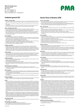
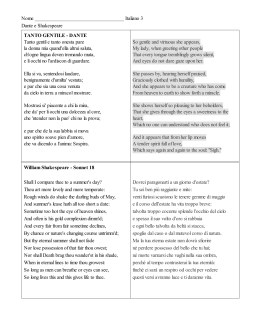
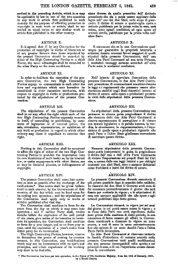
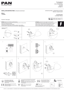
UNIQUA Italia
FUNDAMENTAL RULE
REGOLA FONDAMENTALE
ARRENDERSI? MAI E POI MAI !!
Draft version by: Luciano Crocetti
Translated by: August Atz
Issued on: 1th Jannuary 2007
Previous edition: July 2005
effective: 22th December 2006
Minuta raccolta da: Luciano Crocetti
Tradotta da: August Atz
Rilasciata il: 1. Gennaio 2007
Precedente edizione: Luglio 2005
In vigore dal: 22. Dicembre 2006
UNIQUA ITALIA
Sito : www.420.it e-mail: [email protected]
Si ringrazia per l’aiuto fornito August Atz
2
UNIQUA Italia
3
UNIQUA Italia
PART I - ADMINISTRATION
PARTE I - AMMINISTRAZIONE
_______________________________
________________________________
Section A – GENERAL
Sezione A – GENERALITA’
A.1 GENERAL INFORMATIONS
A.1 INFORMAZIONI GENERALI
A.1.1 The International 420 Class Association
Class rules are closed class rules.
A.1.2 The 420 is a one-design class. The intention
of these rules is to ensure that the boats are as
alike as possible in all respects affecting
performance, in order that crews may compete
against each other on level terms.
A.1.1 Le regole di Classe della Classe 420
Internazionale sono regole di classe chiuse
A.1.2 Il 420 è una classe one-design. L’intenzione
di queste regole è di assicurare che le barche
siano il più possibile simili in tutto ciò che può
influenzare le prestazioni, affinché gli equipaggi
possano competere l’una contro l’altra in condizioni
di parità.
A.1.3 Queste regole sono complementari al Piano
di Costruzione (piano delle forme), le specifiche di
costruzione (Disegno n.5), disegno della deriva
dell’Assiociazione della Classe Internazionale 420
e gli schemi internazionali di misurazione (IMF).
La versione attuale di questi documenti ufficiale è
elencato in fondo di questo documento. Queste
voci quando anche complete, non possono
prevedere ogni possibile situazione che possa
presentarsi. Se un punto non fosse chiaramente
coperto, una decisione si deve ottenere dall’ISAF
tramite il comitato tecnico dell’Associazione della
Classe Internazionale 420.
A.1.3 These rules are complementary to the Lines
plan (plan de formes), the building specifications
(Drawing N° 5), the International 420 Class
Association (ICA) rudder blade drawing and the
420 International Measurement Form (IMF).
The current issue of these official documents is
listed at the end of this document. These items,
however complete, cannot anticipate every
situation that may arise. If a point is not clearly
covered, a ruling shall be obtained from the ISAF
through the ICA technical Committee.
A.2 LANGUAGE
A.2 LINGUA
A.2.1 The official language of the Class is English
and in the event of dispute over interpretation, the
English text shall prevail.
A.2.2 The word “shall“ is mandatory and the word
“may” is permissive.
A.2.3 The term “permanent” shall mean unable to
be removed with simple tools, or fixed with glue or
rivets. For limit marks, it shall mean unable to be
removed and repositioned without destroying
them.
A.2.4 All units are metric and all dimensions
unless otherwise stated are in millimeters.
A.2.1 La lingua ufficiale della classe è l'inglese ed
in caso di contestazione d'interpretazione farà fede
il testo inglese
A.2.2 La parola “deve” significa obbligatorio e la
parola “puó” significa possibile.
A.2.3 La parola “pemanente” significa impossibile
di rimuovere con atrezzi semplici, o fissati con
colla o rivetti. Per le striscie di stazza, lo deve
significare che é impossibile rimuovere o
ripisizionare senza distruggere queste.
A.2.4 Tutte le unità sono metriche e tutte le
dimensioni, se non sta diverso sono millimetriche.
A.3 ABBREVIATIONS
A.3 ABBREVIAZIONI
A.3.1
MNA
ICA
IMF
NCA
ERS
RRS
ISAF International Sailing Federation
ISAF Member National authority
International 420 Class Association
420 International Measurement Form
National Class Associations
Equipment’s Rules of Sailing
Racing Rules of Sailing
A.3.1
ISAF Federazione Internazionale della Vela
MNA ISAF Membro di autoritá Nationale
ICA
International 420 Class Association
IMF
Schema di stazza per il 420
NCA Associazione Nazionale di Classe
ERS Regole per l’Equipaggiamento della Vela
RRS Regolamento di Regata
4
UNIQUA Italia
A.4 AUTHORITIES AND RESPONSABILITIES
A.4 AUTORITA’ E RESPONSABILITA’
A.4.1 The International authority of the class is the
ISAF, which shall co-operate with the ICA in all
matters concerning these class rules.
A.4.2 Neither the ISAF, a MNA, the ICA, a NCA,
a certification authority, or an official measurer
are under any legal responsibility in respect of
these class rules and the accuracy of
measurement, nor can any claims arising from
these be entertained.
A.4.3 Notwithstanding anything contained herein,
the certification authority has the authority to
withdraw a certificate and shall do so on the
request of the ISAF.
A.4.1 L’autoritá internazionale della classe é
l’ISAF, la quale deve co-operare con l’ICA in tutto
quello che concerne queste regole di Classe.
A.4.2 Né l'ISAF, una MNA, l’ICA, una NCA,
un’autoritá di certificazione, o uno stazzatore
ufficiale sono sotto qualsiasi responsabilità legale
per quanto concerne queste regole di classe e
l’accuratezza delle misurazioni, od ogni altro reclamo che possa scaturirne.
A.4.3 Nonostante ognicosa contenente qui dentro,
l’autoritá di certificazione ha l’autoritá di ritirare
un certificato e deve fare cosí come richiesto dalla
ISAF.
A.5 ADMINISTRATION OF THE CLASS
A.5 AMMISTRAZIONE DELLA CLASSE
The Class is administered by the ICA, in
conjunction with the ISAF. The ICA may delegate
parts or all of its functions, as stated in these
class rules, to a MNA or a NCA.
La Classe é amministrata dall’ICA, insieme con
l’ISAF. L’ICA puó delegare parte o tutte le sue
funzioni, come previsto da queste regole di
Classe, a un MNA o a una NCA.
A.6 ISAF RULES
A.6 ISAF RULES
These class rules shall be read in conjunction
with the current version of the ERS. When a term
is used in its defined sense, it is printed in bold
type if defined in the ERS and in italic type if
defined in the RRS.
Queste regole di Classe devono essere lette
insieme con la attuale versione dell’ ERS. Quando
un termine é usato nella sua definizione, é
stampato in grassetto se definito nelle ERS e in
corsivo se definito nelle RRS.
A.7 AMENDMENTS TO THE CLASS RULES
A.7 MODIFICHE ALLE REGOLE DI CLASSE
A.7.1 Amendments to the Class Rules shall be
proposed by the ICA and subject to the approval
of the ISAF in accordance with the ISAF
regulations.
A.7.1 Modifiche alle regole di classe devono
essere proposte dall’ICA e sono soggette
all’approvazione dall’ISAF in accordo con il
regolamento ISAF.
A.8 CLASS RULES VARIATIONS
A.8 VARIAZIONI ALLE REGOLE DI CLASSE
A.8.1 At World or Continental Championships, the
notice of race and sailing instructions may vary
these class rules only with the agreement of the
ICA and the ISAF.
A.8.1 Ai campionati mondiali o continentali , i
comunicati e le istruzioni di regata possono variare
queste regole di classe solamente con il consenso
dell’ICA e dell’ISAF.
A.9 INTERPRETATION OF CLASS RULES
A.9 INTERPRETAZIONE DELLE REGOLE DI
CLASSE
A.9.1 GENERAL
A.9.1 GENERALITA’
Except as provided by A.9.2, interpretation of
these class rules shall be made by the ISAF in
conjunction with the ICA. Request for an
interpretation shall be made in accordance with
the ISAF regulations.
Eccetto per quanto previsto dalla A.9.2,
interpretazione di queste regole di Classe devono
essere fatte dall’ISAF di concerto con l’ICA. La
richiesta di una interpretazione deve essere fatta
in accordo con il regolamento ISAF.
5
UNIQUA Italia
A.9.2 AT AN EVENT
Any interpretation of Class rules required at an
event may be made by an international jury,
constituted in accordance with the RRS appendix
N. In this case, the jury shall consult the event
chief measurer. Such interpretations shall be valid
only during the event, and the organising authority
shall, as soon as practical after the event, inform
the ISAF and the ICA of such an interpretation.
A.9.2 AD UNA MANIFESTAZIONE
Ogni interpretazione delle regole di Classe
richiesta in una manifestazione puó essere fatta da
un giuria internazionale, costituita in accordo con
le RRS appendice N. In questo caso, la giuria
deve consultare il capo stazzatore della
manifestazione. Tale interpretazione deve essere
valida soltanto durante la manifestazione, e
l’autoritá organizzatrice deve, al piú presto
possibile dopo la manifestazione, informare l’ISAF
e l’ICA di tale interpretazione.
A.10 ICA FEE, ICA PLAQUE AND SAIL
BUTTONS
.
A.10.1 The ICA fee is to be set annually by the
ICA and may increase in line with the annual
recommendation from ISAF.
A.10.2 The treasurer of the ICA, after having
received the class fee, shall send to the licensed
builder the ICA Plaque, with the sail number
allocated to the boat.
A.10.3 Licensed builders shall pay for a minimum
of ten plaques each year to the treasurer of the
ICA.
A.10.4 The Sail number for each boat is allocated
by the ICA and specified on the ICA Plaque.
A.10 TASSA dell’ ICA, TARGHETTA dell’ICA E
BOTTONI della VELA
A.10.5 Competitors may use the sail number of
any hull still owned by them, on any boat
chartered or owned by them.
A.10.6 Each sail first certified after 1st march
2005 shall have permanently fixed an officially
numbered ICA sail button. No sail shall be
accepted for certification control without a sail
button. Sail buttons shall not transferred from a
sail to another.
A.10.1 La tassa dell’ ICA é stabilita annualmente
dall’ICA e puo essere aumentata in linea con le
raccomandazioni annuali dell’ISAF.
A.10.2 Il tesoriere dell’ICA, dopo avere ricevuto la
tassa per la Classe, deve spedire al costrutore
licenziatario la targhetta ICA, con il numero velico,
da mettere sull’barca.
A.10.3 Costruttori Licenziatri devono pagare ogni
anno un minimo di dieci targhette al tesoriere
dell’ICA.
A.10.4
Il numero velico per ogni barca é
depositata alla ICA ed é specificata sulla barca.
A.10.5 Regatanti possono usare il numero velico
di ogni scafo di sua proprietá, in prestito o di sua
proprietá.
A.10.6 Ogni vela stazzata la prima volta dopo il
1.Marzo 2005 deve portare permanentemente
fissato un bottone ufficiale numerato dell’ICA.
Nessuna vela deve essere accettato per il
controllo di stazza senza un bottone di vela.
Bottoni di vela non devono essere trasferite da una
vela all’altra.
A.11 CERTIFICATION AND MEASUREMENT A.11 CERTIFICAZIONE E CERTIFICATO DI
CERTIFICATE
CONFORMITA’
A.11.1 For a hull not previously certified,
certification control for all items to be measured
and to be in conformity with the Official documents
shall be carried out by an official measurer, and
the details entered into the IMF which, when
completed, shall be supplied to the owner by the
builder.
A.11.2 Certification control shall be carried out
only by official measurers appointed both by
their MNA and the ICA. An official measurer shall
not perform certification control on any part
owned, designed or build by him, or in which he is
an interested party, or has a vested interest,
except where permitted by these class rules.
A.11.1 Per uno scafo non precedendemente
certificato, il controllo di stazza di tutto questo
deve essere misurato completamente e in
conformitá con i documenti ufficiali e deve essere
fatto da un stazzatore ufficiale, e tutti I dettagli
registrati nel IMF che, quando completato, deve
essere fornito al proprietario della barca dal
costruttore.
A.11.2 Controlli di stazza devono essere fatti
solamente da stazzatori ufficiale, iscritto sia
all’autoritá nazionale e all’ICA. Uno stazzatore
non deve eseguire controlli di stazza a nessuna
parte di sua proprietá, progettate o costruite da lui
stesso, o nella quale é una parte interessata, o
abbia diritti aquisiti, eccetto quando é permesso
6
UNIQUA Italia
A.11.3 The IMF is necessary to obtain the
measurement certificate. The measurement
certificate is obtained as follow :
The owner shall send the IMF together with any
registration fee to the certification authority in
the country where the boat is to be registered.
Upon receipt of a satisfactorily completed IMF and
the fee, the certification authority issues the
measurement certificate to the owner. The
certification authority shall retain a copy of the
IMF.
A.12 VALIDITY
CERTIFICATE.
OF
THE
dalle regole di classe.
A.11.3 l’IMF é necessario per ottenere il
Certificato di Stazza. Il Certificato di Stazza si
ottiene nel modo seguente:
Il proprietaro deve inviare l’IMF insieme con ogni
tassa di registrazione all’autoritá di certificazione
nel paese in cui la barca va registrata. Quando
avrá ricevuto un completo e soddisfacente IMF e
la tassa, l’autoritá certificatrice emetterá il
certificato di stazza al proprietario. L’autoritá
certificatrice deve tenere una copia del IMF.
MEASUREMENT A.12 VALIDITA’ DEL CERTIFICATO DI STAZZA.
A.12.1 A certificate is still valid after an alteration
of the corrector weights only if the hull is reweighed by an official measurer. When the hull
is re-weighed, the measurer shall enter the details
on the IMF and the Measurement certificate shall
be endorsed by the certification authority.
A.12.2 A Measurement certificate becomes
invalid upon :
a) Change of ownership.
b) Alterations other than permitted routine
maintenance such as small repairs, painting,
sanding and polishing to items required by the IMF
to be measured.
c) Withdrawal by the certification authority.
d) The issue of a new certificate.
A.12.1 Un certificato é ancora valido dopo una
variazione dei pesi correttori soltanto se lo scafo
é stato ripesato da uno stazzatore ufficiale.
Quando lo scafo é ri-pesato, lo stazzatore deve
scrivere i dettagli sul IMF e il certificato di stazza
deve essere girato all’autoritá certificatrice.
A.12.2 Un certificato di stazza diventa invalido a
seguito di:
a) Cambiamento di proprietá.
b) Alterazioni diverse che permesse dalla normale
manutenzione, come una piccola riparazione,
verniciatura, levigatura e lucidatura di quello
vincolato dall’IMF, che richiedono una stazzatura.
c) Ritiro dall’ autoritá certificatrice.
d) Il rilascio di un nuovo certificato di stazza.
A.13 RE-CERTIFICATION
A.13 RI-CERTIFICAZIONE
A.13.1 Upon change of ownership, the new owner
shall apply to the certification authority where
the boat will be registered for a new measurement
certificate. The application shall include the old
measurement certificate, the IMF, and any
registration fee that may be required. A new
measurement certificate shall then be issued to
the new owner.
A.13.1 A seguito di un cambio di proprietá, il
nuovo proprietario deve richiedere dall’autoritá
certificatrice, dove la barca é stata registrata, un
nuovo certificato di stazza. La richiesta deve
includere il vecchio certificato di stazza, l’IMF, e
ogni tassa di registrazione che sia richiesta. Un
nuovo certificato di stazza deve essere emesso
al nuovo proprietario.
A.13.2 Upon alteration or repair to an item
required by the IMF to be measured, the relevant
item shall be re-measured by an official
measurer and the details entered on the IMF. The
owner shall apply for a new measurement
certificate ( see A.13.1 for the procedure).
A.13.2 A seguito di una modifica o riparazione di
punti vincolati dal IMF, che richiedono una
stazzatura, si deve procedere alla ri-stazzatura dei
punti rilevanti da uno stazzatore ufficiale e tutti i
dettagli devono essere registrati sull’IMF. Il
proprietario deve richiedere un nuovo certificato
di stazza (vedi a.13.1 per la procedura).
A.13.3 When the certificate has become invalid A.13.3 Quando il certificato diventa invalido a
under A.12.2 (c), the certification authority may seguito di A.12.2 (c), l’ autoritá certificatrice, a
issue a new certificate at its discretion.
sua discrezione, puo emettere un nuovo
certificato di stazza.
7
UNIQUA Italia
Section B – BOAT ELIGIBILITY
Sezione
BARCA
B
–
REQUISITI
DELLA
For a boat to be eligible to race, the rules in this Affinché una barca abbia i requisiti per regatare,
section shall be complied with.
deve essere conforme alle regole di questa
sezione.
B.1 CERTIFICATE
B.1 CERTIFICATO
No crew shall take part in class races unless the
boat has a valid measurement certificate, in
English or with English subtitles, including
corrector weight details.
Nessun’ equipaggio deve partecipare a regate di
Classe senza che la suo barca sia munito di un
certificato di stazza valido, in inglese o con i
sottotitoli in inglese, inclusa i dettagli dei pesi
correttori.
B.2 CERTIFICATION MARKS
B.2 MARCHIO DI CERTIFICAZIONE
Each sail shall carry a valid certification mark Ogni vela deve portare un valido marchio di
certificazione in accordo con G.2.1.
according to G.2.1.
B.3 CLASS MEMBERSHIP
B.3 APPARTENENZA ALLA CLASSE
The crew shall be current members of a NCA.
L’equipaggio deve essere attuale membro di una
NCA .
B.4
INTERNATIONAL
ASSOCIATION PLAQUE
420
CLASS B.4
TARGA
DELLA
ASSOCIAZIONE
INTERNAZIONALE CLASSE 420.
The ICA Plaque shall be affixed to the hull, as La targa dell’ICA deve essere fissata allo scafo,
specified in D.1.5
come specificato nella D.1.5
B.5 INTERNATIONAL 420 BUILDER’S PLAQUE
B.5 TARGA DEL CONSTRUTTORE DEL 420
The builder’s Plaque shall be affixed to the hull, La targa del costruttore deve essere affissa allo
scafo, come specificato nella D.1.5
as specified in D.1.5
8
UNIQUA Italia
PART II – REQUIREMENTS AND LIMITATIONS
PARTE II – REQUISITI E LIMITAZIONI
The crew and the boat shall comply with the rules
in Part II when racing. Measurement to check
conformity with rules of Section C is not part of
equipment certification control.
L’equipaggio e la barca devono essere conformi
con le regole di classe nella parte II durante le
regate. Misurazioni per controllo di conformitá con
le regole di classe della Sezione C non sono parte
della certificatione dell’equipaggiamento.
Section C
RACING
–
CONDITIONS
FOR Sezione C
REGATARE
C.1 GENERAL
C.1 GENERALE
C.1.1 MEASUREMENT
C.1.1 STAZZE
–
CONDIZIONI
PER
Unless otherwise stated, measurement shall be Se non é specificato diversamente, la stazza deve
carried out in accordance with the current version essere eseguita in accordo con la versione attuale
of the ERS.
delle ERS.
C.1.2 RULES
C.1.2 REGOLE
C.1.2.1 Except on a beat to windward, when
surfing (rapidly accelerating down the leeward
side of a wave) or planing is possible, the crew
may pump in order to initiate surfing or planing,
but not by means of body pumping and only once
for each wave or gust of wind.
C.1.2.2 The race committee may permit boats to
rock, pump and ooch on a leg of the course when,
prior the leg, the wind is consistently 13 knots or
above, measured at deck level. To do so, the
racing committee shall include in the Sailing
instructions the appropriate paragraphs from
Appendix LE of the Racing Rules of Sailing.
C.1.2.3 RRS 49.1 is modified as per class rules
C.3.2.
C.1.2.1 Eccetto su un lato di bolina (sopravento),
quando surfing (accelerando rapidamente il lato
sottovento giú di un' onda) o planare è possibile,
l’equipaggio può pompare in ordine per iniziare il
surfing o la planata, ma non si intende pompare
con il corpo e solamente una sola volta per ogni
onda o raffica di vento.
C.1.2.2 Il commitato di regata puó permettere a
barche di rollare, pompare e spingere su un lato di
percorso quando, prima del lato, il vento ha
costantamente 13 nodi o oltre, misurato al livello
della coperta. Per fare cosi, il comitato di regata
deve includere nelle istruzioni di regata il relativo
paragrafo dal Appendice LE delle RRS.
C.1.2.3 RRS 49.1 é modificato con la regola di
classe C.3.2.
C.2 CREW
C.2 EQUIPAGGIO
C.2.1 LIMITATIONS
C.2.1 LIMITAZIONI
C.2.1.1 The crew shall consist of two persons,
each in contact with the boat.
C.2.1.2 No crew member shall be substituted
during an event without the approval of the Race
Committee.
C.2.1.1 L’equipaggio deve consistere in due
persone, ciascuna a contatto con la barca.
C.2.1.2 Nessun membro dell’equipaggio deve
essere sostituito durante una manifestazione
senza l’approvazione del Comitato di Regata.
C.2.2 RESPONSIBILITY OF THE CREW
C.2.2 RESPONSABILITA’ DELL’EQUIPAGGIO
It is the crew’s responsibility to ensure that the E’ responsabilitá dell’equipaggio assicurarsi che
boat and personal equipment comply with the la barca ed l’equipaggiamento personale sia
Class rules when racing.
conforme alle regole di Classe durante le regate.
9
UNIQUA Italia
C.3 PERSONAL EQUIPMENT.
C.3 EQUIPAGGIAMENTO PERSONALE.
C.3.1 MANDADORY
C.3.1 OBBLIGATORIO
When racing, each crew member shall wear
personal bouyancy to the minimum standard
EN.393 (CE 50N) or equivalent. Inflatable
buoyancy vests are not permitted.
RRS 43.1 shall apply, with the amendment that
each crew member’s personal equipment shall
weigh 9 kg maximum, including footwear and
clothing worn below the knees but excluding the
trapeze harness.
Durante la regata, ogni membro dell’equipaggio
deve indossare un salvagente personale con il
minimo standard EN.393 (CE 50N) o equivalente.
Giubotti gonfiabili non sono permessi.
La 43.1 del RRS si deve applicare, con la modifica
che l’equipaggiamento personale per ciascun
membro dell’equipaggio deve pesare al massimo
9 kg, incluse le calzature e vestiti indossati al di
sotto delle ginocchia ma escluso la braga per il
trapezio.
C.3.2 OPTIONAL
C.3.2 FACOLTATIVO
As an alteration to RRS 49.1, a trapeze may be
used, but only one member of the crew shall use
a trapeze harness. The trapeze harness shall not
be filled with ballast, shall float, and shall have a
maximum weight of 4 kg (Weight shall be
determined as required by RRS Appendix H).
A modifica della 49.1 del RRS, puó essere usato
un
trapezio,
ma
soltanto
un
membro
dell’equipaggio deve usare una braga del
trapezio. La braga del trapezio non deve essere
riempito di zavorra, deve galleggiare, e deve
avere un peso massimo di 4 kg (Il peso deve
essere determinato come previsto dal RRS
Appendice H).
.
10
UNIQUA Italia
C.4 ADVERTISING
C.4 PUBBLICITA’
C.4.1 CATEGORY
Advertising is permitted in accordance with the
ISAF Regulation 20 : Advertising code (category
C) excepted by amended by C.4.2.
C.4.1 CATEGORIA
La pubblicità è consentita in accordo con il
regolamento 20 dell’ISAF: Pubblicità codice
(categoria C) ad eccezione per quanto modificato
dalla C.4.2.
C.4.2 LIMITATIONS
C.4.2 LIMITAZIONI
Advertising is permitted only in following positions
(see diagram 1):
(a) Event advertising :
Hull : the outside hull shell between 600 mm
and 1650 mm from the foremost point (fittings
excluded)
(b) Competitor advertising :
Hull : the outside hull shell aft of 1650 mm
from the foremost point (fittings excluded)
Mainsail : below sail numbers
Spinnaker : below sail numbers.
La pubblicità è consentita soltanto nelle seguenti
posizioni (vedi diagramma 1):
(a) Pubblicità della manifestazione:
Scafo: opera morta tra 600 mm e 1650 mm dalla
estrema prua (attrezzatura esclusa)
C.4.3 IDENTIFICATION DURING RACES
C.4.3
IDENTIFICAZIONE
REGATA
(b) Pubblicità del concorrente:
Scafo: L’opera morta dello scafo a poppavia di
1650 mm dalla estrema prua (attrezzatura
esclusa).
Randa : al di sotto dei numeri velici.
Spinnaker : al di sotto dei numeri velici.
DURANTE
LA
The outside hull shell between the foremost point L’opera morta dello scafo tra il punto all’estrema
and 600 mm from the foremost point shall be prua e 600 mm da esso deve essere lasciata
intend only for the boat identification if specified in soltanto per l’identificazione della barca se
11
UNIQUA Italia
the Sailing Instructions, or shall be without specificato nelle Istruzioni di Regata, o deve
advertising if nothing is specified in the Sailing essere lasciata senza publicitá se nulla é
instructions (see diagram 1)
specificato nelle Istruzioni di Regata (vedi
diagramma 1).
C.5 PORTABLE EQUIPMENT
C.5 EQUIPAGGIAMENTO PORTABILE
C.5.1 FOR USE
C.5.1 PER L’USO
a) FACOLTATIVO
a) OPTIONAL
1) One hand bailer or bucket and/or sponge
1) Una sassola o secchio e/o spugna
2) One magnetic compass (electronic devices
2) Una bussola magnetica (dispotivi elettronici
are not permitted) fixed to a mounting
non sono permessi) fissati a una staffa di
bracket. The compass shall not recess into
montaggio. La bussola non deve essere
either side tank or deck. The mounting
incassata nei gavoni laterali o sulla coperta.
bracket may be attached on the mast or may
La staffa di montaggio può essere fissata
sull’albero o puó essere usata per chiudere la
be used to close the mast gate.
uscita della mastra.
3) Electronic or mechanical timing devices,
3) Orologio electronico o meccanico, che deve
which shall be removable.
essere rimobibili.
C.5.2 NOT FOR USE
C.5.2 NON PER L’USO
a) OPTIONAL
a) FACOLTATIVO
1) One paddle
1) Una pagaia
2) Spare parts such as blocks, shackles, ropes
3) Parte delle antenne come bozzelli, grilli, cime
etc.
ecc.
b) MONDADORI
b)
1) The boat shall be fitted with a floating towing 1)
rope of a minimum length of 8 meters and
minimum diameter of 8 mm, secured to the mast,
and which can be grasped at the stem (even if the
boat is capsized) from a rescue boat.
OBBLIGATORIO
La barca deve essere attrezzata con una cima
da traino galleggiante lunga almeno 8 metri e
con diametro minimo di 8 mm, assicurata
all’albero, e che possa essere afferrata alla
prua (perfino se la barca é scuffiata) da una
barca di soccorso.
C.6 BOAT
C.6 LA BARCA
C.6.1 WEIGHT
C.6.1 IL PESO
The boat fully rigged for sailing and in dry
conditions, but excluding sails, towing rope,
personal and portable equipment shall have a
minimum weight of 100 kg. A compass with
associated bracket, if present, shall be included in
the boat weight. Corrector weights, including any
required by C.6, shall have a maximum weight of
2 kg.
La barca completamente attrezzata per la
navigazione e in condizioni asciutta, ma escluse le
vele, cima di traino, equipaggiamento personale
e portabile, deve avere un peso minimo di 100Kg.
Una bussola con la loro staffa, se presente, deve
essere incluso nel peso della barca. Pesi
correttori, incluso tutto il richiesto dal C.6, devono
avere un peso massimo di 2 kg.
C.6.2 FLOTATION
C.6.2 GALLEGGIABILITA’
C.6.2.1 The boat shall have two side buoyancy
tanks and one in the front. At initial certification
control, the measurer shall check the watertightness of the buoyancy tanks, inspection ports
and drain plugs. If the buoyancy is unsatisfactory,
the measurer shall not sign the IMF until
satisfactory remedial measures have been taken.
C.6.2.1 La barca deve avere due gavoni di
galleggiamento laterali e uno a prua. Al controllo
di stazza iniziale, lo stazzatore deve verificare la
tenuta all’acqua dei gavoni, dei fori d’ispezione e
dei tappi di drenaggio. Se la galleggiabilitá é
insoddisfacente, lo stazzatore non deve firmare
l’IMF finché la verifica dei rimedi presi non sia
12
UNIQUA Italia
There after, it is the responsibility of the
competitor/owner to ensure the water-tightness of
these tanks.
C.6.2.2 Inspections hole covers and drainage
plugs shall be kept in place when racing.
soddisfacente. Dopo di ció, é responsabilitá del
concorrente/proprietario di assicurare la tenuta
all’acqua di questi gavoni.
C.6.2.2 I tappi dei fori d’ispezione dei gavoni e i
tappi di drenaggio devono essere tenuti al loro
posto durante la regata.
C.7 HULL
C.7 LO SCAFO
C.7.1 FITTINGS
C.7.1 ATTREZZATURA
Rigging and fittings listed hereunder shall be
fitted and used only as specified. Except where
otherwise specified, the direction of the control
lines, sheets and ropes shall not be modified by
means of shackles, rings, loops, thimbles or holes
in the boat. Fittings listed hereunder shall comply
with the current class rules. All fittings, fastenings
and local reinforcement for fittings shall be only for
their normal purpose and shall not be used to
increase the weight of the boat.
Le manovre e le attrezzature sottoelencate
devono essere montate e usate soltanto come
specificate. Eccetto quando é specificato diverso,
la direzione delle manovre, scotte e cime non deve
essere modificato per mezzo di grilli, anelli,
ponticelli, redance o fori nella barca. Le
attrezzature sottoelencate devono essere conformi
con le attuali regole di Classe. Tutte le
attrezzature, fissaggi e locali rinforzi per le
attrezzature devono essere solamente per lo
scopo normale e non deve essere usato per
aumentare il peso della barca.
C.8 HULL APPENAGES
C.8 APPENDICI DELLO SCAFO
C.8.1 LIMITATIONS
C.8.1 LIMITAZIONI
Only one centreboard and one rudder blade
shall be used during an event except in case of
loss or damage beyond repair. Such replacement
may be made only with the approval of the race
committee.
Soltanto una deriva ed una pala del timone
devono essere usati durante una manifestazione
eccetto a causa di perdita o danneggiamento non
riparabile. Tale sostituzione puó essere fatto
soltanto con l’approvazione del comitato di regata.
C.8.2 CENTREBOARD
C.8.2 DERIVA
(a) USE
(a) USO
The centreboard shall be fitted by means of an La deriva deve essere fissata utilizzando un perno
axis pin throughout a hole in the centreboard passante attraverso un foro sulla cassa di deriva,
13
UNIQUA Italia
case, which may include a bushing. When fully che puo includere una boccola. Quando
raised, no part of the centreboard shall project completamente sollevata, nessuna parte della
deriva deve uscire da sotto la superfice dello
below the hull surface.
scafo.
C.8.3 RUDDER
C.8.3 TIMONE
(a) USE
(a) USO
No part of the rudder blade, when fully lowered,
shall extend more than 540 mm below the HDP.
The leading edge of the rudder blade shall not be
forward of a vertical line through the HDP (see
measurement diagram 2).
Nessuna parte della pala del timone, quando
completamente abbassata, deve estendersi oltre
540 mm al di sotto del HDP. Il profilo anteriore
della pala del timone non deve essere avanti oltre
ad una linea verticale rispetto al HDP (vedi
diagramma 2).
C.9 RIG
C.9 RIG
C.9.1 LIMITATIONS
C.9.1 LIMITAZIONI
Only one mast, boom and spinnaker pole shall
be used during an event, except in case of loss or
damage beyond repair. Such replacement may be
made only with the approval of the Race
Committee.
Soltanto un’albero, boma e tangone devono
essere usati durante una manifestazione, eccetto
a causa di perdita o danneggiamento non
riparabile. Tale sostituzione puó essere fatto
soltanto con l’approvazione del comitato di regata.
C.9.2 MAST
C.9.2 ALBERO
a) USE
a) USO
1) Chocks may be used to control the fore and
aft bend of the mast spar at the mast partner.
2) The mast heel position shall not be adjusted
on the mast step when racing.
3) Adjustable spreaders –if used- shall not be
able to be remotely controlled, and shall not be
adjusted when racing.
4) The effective length of the shrouds shall not
be adjusted when racing.
1) Zeppe possono essere usate per cotrollare la
curvatura avanti e indietro dell’albero alla mastra.
2) La posizione del piede dell’albero non deve
essere regolabile alla scassa durante la regata.
3) Crocette regolabile –se usate- non devono
essere abilitate di un rimosso controllato, e non
devono essere regolabile durante la regata.
4) La lunghezza effettiva delle sartie non deve
essere regolabile durante la regata.
5) The forestay under tension shall be entirely in
metal and shall prevent the mast from disengaging
from the mast partners. To meet this requirement
the widest section of the mast shall be within the
5) Lo strallo sotto tensione deve essere
interamente di metallo e deve pervenire che
l’albero esca dalla mastra. Per corrispondere a
questa richiesta la sezione piú larga dell’albero
14
UNIQUA Italia
mast partners when the mast rakes under its own
weight and the forestay comes under tension, as
in Diagram 3. The forestay shall be connected to
the stemhead fitting with either: a shackle, a
rigging plate with holes and pins, a steel wire rope
strop of minimum diameter of 2mm or any
combination of this above. Elastic rope tied on the
forestay and the stemhead is permitted.
deve essere entro la mastra quando poggia
(rake) sotto il suo peso e lo strallo venga sotto
tensione, come nel diagramma 3. Lo strallo deve
essere collegato all’attrezzatura di prua con uno
qualunque: un grillo, una landina con buchi e
perni, un cavetto d’acciaio con un diametro
minimo di 2mm o qualsiasi combinazione di
quanto sopra. É permesso una cima elasica
tenuta sullo strallo e la ferramenta di prua.
C.10 SAILS
C.10 VELE
C.10.1 MAINTENANCE
C.10.1 MANUTENZIONE
C.10.1.1 Routine maintenance such as sewing,
mending and patching is permitted without recertification. Altered sails shall be re-certified
and the official measurer shall place a new
certification mark on the sail with the new date
of certification control.
C.10.1.1 La normale manutezione come la
cucitura, riparazione e raforzamento é permessa
senza ri-stazzatura. Vele modificate devono
essere ri-stazzate e lo stazzatore ufficiale deve
apporre un nuovo segno di stazza sulla vela con
la nuova data della stazza fondamentale.
C.10.2 LIMITATIONS
C.10.2 LIMITAZIONI
C.10.2.1 Not more than one mainsail, one jib and
one spinnaker shall be carried aboard when
racing.
C.10.2.2 Not more than one mainsail, one jib and
one spinnaker shall be used during an event,
except when a sail has been lost or damaged
beyond repair, or when otherwise specified in the
sailing instructions. Such replacement may be
made only with the approval of the race
committee.
C.10.2.1 Non piú di una randa, un fiocco ed uno
spinnaker devono essere trasportati a bordo
durante la regata.
C.10.2.2 Non piú di una randa, un fiocco ed uno
spinnaker devono essere usati durante una
manifestazione, ad eccezione quando una vela é
stata persa o danneggiata in modo non riparabile,
o quando é prevvisto diversamente dalle istruzioni
di regata. Tale sostituzione puó essere effettuta
solo con l’approvazione del Comitato di Regata.
C.10.3 MAINSAIL
C.10.3 RANDA
C.10.3.1 IDENTIFICATION
C.10.3.1 IDENTIFICAZIONE
Identification shall comply with RRS except where
mentioned hereunder :
As an alteration to RRS Appendix G 1.3 (a), the
following items shall be positioned on each side of
the sail as follows :
(a) National letters above and below and adjacent
to the second batten from the top, port and
starboard not overlapping each other, those on
starboard side being uppermost .
(b) Sail numbers above and below and adjacent
to the third batten from the top, port and starboard
not overlapping each other, those on starboard
side being uppermost.
(c) Mainsails used in woman’s only events shall
carry a red rhombus (length of diagonals 250mm
minimum) above the top batten pocket on both
sides. The position should be approximately in the
centre of the triangle formed by the top batten and
L’identificazione deve essere conforme con le
RRS eccetto per quanto mezionato quisotto:
Ad una modifica del RRS Appendice G 1.3 (a), le
seguenti parti devono essere posizionate su
ciascun lato della vela come segue:
(a) Lettere Nazionali al di sopra ed al di sotto ed
adiacenti alla seconda stecca partendo dall’alto,
sinistra e dritta senza sovrapporsi l’una all’altra,
essendo quelle sul lato di dritta le piú alte.
(b) Numeri velici al di sopra ed al di sotto e
adiacente alla terza stecca partendo dall’alto,
sinistra e dritta senza sovrapporsi l’una all’altra,
essendo quelle a dritta le piú alte.
(c) Rande usate in manifestazioni di solo donne
devono portare un rombo rosso (lunghezza del
diagonale 250mm minimo) su entrambe i lati
sopra la tasca della stecca superiore. La posizione
dovrá essere approssimamente nel centro del
15
UNIQUA Italia
the mainsail head. The rhombus may be retained triangolo che é formato dalla stecca superiore e la
tavoletta della randa. Il rombo può rimanere per
for racing in other events.
regatare in altri manifestazioni.
Numbers and letters shall be in red, of a minimum Numeri e lettere devono essere in rosso, con una
width of 200 mm (except number 1 and letter I), of larghezza minima di 200 mm (eccetto il numero 1
a minimum thickness of 45 mm and of a minimum e la lettera I), di uno spessore minimo di 45 mm e
height of 300 mm. Other dimensions and di un altezza minima di 300mm. Altre dimensioni e
indications regarding letters and numbers are indicazioni riguardanti lettere e numeri sono
specified in RRS.
specificate nelle RRS.
All numbers, letters and the emblem shall be of Tutti i numeri, lettere e l’emblema devono essere
paint or other, securely attached durable material. pitturati o altro, di materiale durabile fissati
accuratamente .
C.10.3.2 USE
C.10.3.2 USO
C.10.3.2.1 The sail shall be hoisted on a halyard.
The arrangement shall permit hoisting and
lowering of the sail while afloat with the boat
upright.
C.10.3.2.2 The sail shall be set so that the highest
visible point of it, projected at 90° to the mast
spar, shall not be higher than the upper point,
and the aft-most visible part of the leech,
projected at 90° to the boom spar, is forward of
the outer point on the boom.
C.10.3.2.1 La vela deve essere issata da una
drizza. Il provvedimento deve permettere di issare
ed ammainare la vela mentre si é in mare con la
barca eretta.
C.10.3.2.2 La vela deve essere cosí posizionata
che il punto visibile piú alto di essa, proiettato a
90° rispetto all’albero, non deve essere al di sopra
del limite superiore, e il punto visibile piú a poppa
della balumina, proiettato a 90° rispetto al boma,
é a pruavia del limite esterno sul boma.
C.10.3.2.3 Luff and foot bolt ropes shall be in the C.10.3.2.3 Il gratile dell’inferitura e della base
respective spar grooves or tracks.
devono essere inferiti nella rispettiva canaletta.
C.10.4 JIB
C.10.4 FIOCCO
C.10.4.1 USE
C.10.4.1 USO
The sail shall be hoisted on a halyard. The La vela deve essere issata da una drizza. Il
arrangement shall permit hoisting and lowering of provvedimento deve permettere di issare ed
the sail while afloat with the boat upright.
ammainare la vela mentre si é in mare con la
barca eretta.
C.10.4.2 Only one steel luff wire of minimum C.10.4.2 Solamente un cavetto (ghinda) con un
diameter of 2mm shall be fitted inside the jib luff diametro minimo di 2mm deve essere montato all’
sleeve when racing.
interno dell’inferitura del fiocco durante la regata.
C.10.5 SPINNAKER
C.10.5 SPINNAKER
C.10.5.1 Identification
C.10.5.1 Identificazione
Identification shall comply with RRS, except when
mentioned hereunder :
As an alteration to RRS Appendix G 1.3 (d),
national letters are optional.
If positioned, national letters may be in line with
the sail numbers. The colour of letters and
numbers is optional, but they shall be all of the
same colour, fully painted, and shall contrast with
the colour of the panel to which they are
positioned, of a minimum width of 200 mm (except
number 1 and letter I), of a minimum thickness of
45 mm and of a minimum height of 300 mm. Other
L’identificazione deve essere conforme con l’RRS,
eccetto per quanto menzionato quisotto:
A modifica del RRS Appendice G 1.3 (d), le lettere
nazionali sono facoltativi.
Se messe, le lettere nazionali possono essere in
linea con il numero velico. Il colore delle lettere e
nummeri é facoltativo, ma essi devono essere tutti
dello stesso colore, pitturato a pieno, e devono
contrastare con il colore del ferzo dove sono
posizionati, con una larghezza minima di 200 mm
(eccezione il numero 1 e la lettera I), di uno
spessore minimo di 45 mm ed un altezza minima di
16
UNIQUA Italia
dimensions and indications regarding letters and
numbers are specified in RRS.
All numbers and letters shall be of paint or other,
securely attached durable material. Numbers and
letters, if on both sides, shall not overlap and shall
be placed at different heights with a minimum
space of 60 mm.
300 mm. Altre dimenzioni ed indicazioni riguardanti
lettere e numeri sono specificate nell’ RRS.
Tutti i numeri e le lettere devono essere pitturati o
altro, di materiale durabile fissati accuratamente.
Numeri e lettere, se su entrambe i lati, non si
devono sovrapporre e devono essere posti a
differenti altezze con un spazio minimo di 60 mm.
C.10.5.2 USE
The sail shall be hoisted on an halyard. The
arrangement shall permit hoisting and lowering of
the sail while afloat with the boat upright.
C.10.5.2 USO
La vela deve essere issata da una drizza. Il
provvedimento deve permettere di issare ed
ammainare la vela mentre si é in mare con la
barca eretta.
17
UNIQUA Italia
Section D – HULL AND DECK
Sezione D – SCAFO E COPERTA
D.1 CERTIFICATION
D.1 CERTIFICAZIONE
D.1.1 Only an official measurer shall measure
the hull and sign the declaration on the IMF that it
complies with the class rules, lines plan and
building
specification
(Drawing
N°
5).
Measurements to ensure the conformity of the
hull are specified on the IMF but the intention is
that beyond these measurements, the hull shall
be completely conform to the Official Documents.
D.1.5 No boat shall leave the builder’s premises
without the ICA plaque and the builder's plaque
affixed. The builder's Plaque shall mention :
- The trade mark of the boat
- The name and the address of the builder
- The year of building.
The ICA plaque shall mention:
- The ISAF logo
- The ICA logo
- The sail number allocated to the boat
The ICA plaque shall be affixed on the starboard
side tank, close to the transom and the builder's
plaque on the inside transom (see also rule B.4
and B.5)
D.1.1 Soltanto uno stazzatore ufficiale deve
misurare lo scafo e firmare la dichiarazione sul IMF
che é conforme con le regole di Classe, piano e
specifiche di costruzione (disegno n. 5). Le
misurazioni per assicurare la conformitá dello
scafo sono specificate nell’IMF ma l’intenzione é
che al di lá di queste misurazioni, lo scafo deve
essere completamente conforme ai Documenti
Ufficiali.
D.1.2 Per essere certificati in conformitá con le
regole di Classe, Piano e specifiche di
costruzione (Disegno n. 5) lo scafo deve essere
conforme con i documenti ufficiali in vigore al
momento della iniziale stazza fondamentale.
D.1.3 La stazzatura deve essere portata avanti in
accordo con la versione attuale delle ERS.
D.1.4 Le seste usate per la stazza fondamentale
dello scafo devono essere forniti dall’ISAF.
Le tolleranze sono date soltanto per consentire
piccoli errori di costruzione e che non devono
essere usate deliberatamente per modificare il
progetto. La barca, prima di lasciare il cantiere del
costruttore deve essere stazzata da uno
stazzatore ufficiale. Lo stazzatore deve riportare
sull’ IMF ció che egli considera difforme dalla
natura e dal progetto della barca, ed il certificato di
stazza puó essere rifiutato.
D.1.5 Nessuna barca deve lasciare i cantieri senza
avere affisse la targa ICA e la targa del costruttore.
La targa del costruttore deve riportare:
- Il marchio della barca
- Il nome ed l’indirizzo del Costruttore
- L’anno di costruzione
La targa ICA deve riportare:
- Il logo ISAF
- Il logo ICA
- Il numero velico assegnato alla barca
La targa ICA deve essere fissata sul gavone
laterale di dritta, vicino alla poppa e la targa del
costruttore all’interno della poppa (vedi anche
regola B.4 e B.5).
D.2 BUILDERS
D.2 COSTRUTTORI
D.2.1 International 420 hulls shall be moulded
and assembled only by licensed builders.
Application for a licence shall be made to the ISAF
which shall consult with the ICA and the MNA of
the country where the builder has its yard before
granting a licence. Hulls shall be supplied only as
permanently assembled boat units.
D.2.1 Gli scafi del 420 Internazionale devono
essere sagomati ed assemblati soltanto da
costruttori licenziatari.
La richiesta per una licenza deve essere fatta
all’ISAF che si deve consultare con l’ICA e la MNA
del paese dove il costruttore ha il suo cantiere al
momento prima di concedere la licenza. Scafi
devono essere forniti soltanto in pemanentemente
D.1.2 To be certified in conformity with the class
rules, Lines Plan and Building specification
(Drawing N° 5) the hull shall comply with the
official documents in force at the time of initial
certification control.
D.1.3 Measurement shall be carried out in
accordance with the current version of the ERS.
D.1.4 Templates used for certification control of
hull shall be supplied by the ISAF.
Tolerances are only given to allow minor building
errors and shall not be deliberately used to alter
the design. The boat, before leaving the builder’s
premises shall be measured by an official
measurer. The measurer shall report on the IMF
what he considers being a departure from the
intended nature and design of the boat, and the
measurement certificate may be refused.
18
UNIQUA Italia
Rigs, sails, hull appendages and fittings may be assemblati unitá di barca.
Antenne, vele,
appendici dello scafo ed attrezzature possono
produced by any manufacturer.
essere prodotte da qualsiasi costruttore.
D.2.2 Licensed builders have the sole D.2.2 I Costruttori Licenziatari hanno la sola
responsibility that their production moulds, plugs responsabilitá che gli i controstampi per la loro
and assembled boats comply with the relevant produzione, tappi e gli scafi assemblati sono
class rules and official documents.
conformi alle rilevanti Regole di Classe ed i
documenti ufficiali.
D.2.3 If a builder does not comply with the D.2.3 Se il costruttore non é conforme alle
requirements quoted in the class rules and the richieste quote delle Regole di Classe ed i
Official documents, the ISAF may revoke the documenti ufficiali, l’ISAF puó revocare la Licenza
licence on the recommendation of the ICA.
di Costruttore su raccomandazione dell’ICA
D.2.4 If a builder is found to have supplied a boat D.2.4 Se un costruttore é trovato ad avere fornito
that does not comply with the rules in application, una barca che non é conforme con le regole da
he shall be liable to rectify the error, and may have applicare, egli (deve) é costretto di correggere
his licence as a builder withdrawn.
l’errore, e puó essere ritirato la sua licenza di
costruttore.
D.3 BUILDING
BUILDING
AND
MATERIALS
FOR
D.3 COSTRUZIONE E MATERIALI PER LA
COSTRUZIONE
D.3.1 The hull shall be build in conformity with the
building specifications (Drawing N° 5)
D.3.2 Materials used for building shall be those
specified on the Building specification (Drawing
N° 5).
D.3.3 No less than 0.05 m³ of positive buoyancy
shall be securely attached in each side tank to
give approximately equal buoyancy laterally and
longitudinally. The buoyancy shall be of closed cell
rigid foam or alternatively of air containers of not
less than two litres each. It shall not be used as
reinforcement.
D.3.1 Lo scafo deve essere costruita in conformitá
con le specifiche di costruzione (Disegno n. 5).
D.3.2 I materiali usati per la costruzione devono
essere quelli specificati sulle specifiche di
costruzione (Disegno n. 5).
D.3.3 Non meno di 0.05 m3 di galleggiante positivo
deve essere fissato accuratamente in entrambe i
gavone laterale per dare approssimamente uguale
galleggiabilitá sia laterale che longitudinale. Il
galleggiante deve essere un espanso a celle
chiuse o alternativamente un contenitore d’aria di
non meno di due litri per ciascuno. Non deve
essere usato come rinforzo.
D.3.4 Non-slip material, tape and low-friction D.3.4 Materiale anti-scivolo, nastro e matreriale di
material not exceeding 4mm in thickness may be basso-strofinamento non superando lo spessore di
added to the hull as long as it does not change 4mm puó essere aggiungiunto lungo lo scafo che
the stiffness of the hull.
questo non cambia la rigiditá dello scafo.
D.4 ASSEMBLED HULL
D.4 SCAFO ASSEMBLATO
D.4.1 DIMENSION AND MEASUREMENT.
D.4.1 DIMENSIONI E STAZZA
D.4.1.1 The hull datum point (HDP) is the
intersection on the hull centre plane of the
transom external surface with the underside of the
hull surface, both extended as necessary.
The aft measuring point (AMP) is the projection of
the HDP on the baseline.
D.4.1.2 For fundamental measurement of the
boats built by current fully licensed builders after
the 1st January 2007 the baseline shall be set at
200 mm below the HDP and 92 mm below the
keel at 3780 mm from the HDP. For new builders
the effective date is 1st March 2006. All
measurements carried out from the HDP shall be
made parallel to the baseline and depth
D.4.1.1 Il punto dato dello scafo (HDP) é
l’intersezione della linea centrale dello scafo alla
parte esterna della poppa con l’ opera viva dello
scafo, entrambe prolungati se neccessario.
Il punto di misurazione di poppa dello scafo (AMP)
é la projezione del HDP sulla linea di base.
D.4.1.2 Per la stazza fondamentale delle barche
costruite da tutti attuali costruttori licienzatari dopo
il 1. Gennaio 2007 la linea di base deve essere
posizionato a 200 mm sotto il HDP e 92 mm sotto
la chiglia a 3780 mm dal HDP. Per costruttori
nuovi la data effettiva é il 1. Marzo 2006. Tutte le
misurazioni portate avanti dal HDP devono essere
fatte parallele alla linea di base e le misurazione di
19
UNIQUA Italia
measurements perpendicular to the baseline.
Measurement section shall be perpendicular to the
baseline.
D.4.1.3 The hull length, shall be minimum 4180
mm and maximum 4220 mm.
D.4.1.4 Measurement sections 1 to 10 shall be at
following positions from the HDP:
Section 1: at 380 mm from HDP.
Section 2: at 780 mm from HDP.
Section 3: at 1180 mm from HDP.
Section 4: at 1580 mm from HDP.
Section 5: at 1980 mm from HDP.
Section 6: at 2380 mm from HDP.
Section 7: at 2780 mm from HDP.
Section 8: at 3180 mm from HDP.
Section 9: at 3580 mm from HDP.
Section 10: at 3980 mm from HDP.
profonditá per pendicolare alla linea di base.
Sezioni di misurazioni devono essere pendicolare
alla linea di base.
D.4.1.3 La lunghezza dello scafo, deve essere
minimo 4180 mm e massimo 4220 mm.
D.4.1.4 Le sezioni di stazza 1 a 10 devono essere
alle seguenti posizioni dal HDP:
Sezione 1: a 380 mm dal HDP.
Sezione 2: a 780 mm dal HDP.
Sezione 3: a 1180 mm dal HDP.
Sezione 4: a 1580 mm dal HDP.
Sezione 5: a 1980 mm dal HDP.
Sezione 6: a 2380 mm dal HDP.
Sezione 7: a 2780 mm dal HDP.
Sezione 8: a 3180 mm dal HDP.
Sezione 9: a 3580 mm dal HDP.
Sezione 10: a 3980 mm dal HDP.
Vertical distance from baseline to underside of hull Distanza vericale dalla linea di base allo scafo
shell;
Minimum
Maximum
deve ;
Minimum
Maximum
Section 1:
154 mm
170 mm
Sezione 1:
154 mm
170 mm
Section 2:
116 mm
132 mm
Sezione 2:
116 mm
132 mm
Section 3:
84 mm
100 mm
Sezione 3:
84 mm
100 mm
Section 4:
55 mm
71 mm
Sezione 4:
55 mm
71 mm
Section 5:
34 mm
50 mm
Sezione 5:
34 mm
50 mm
Section 6:
20 mm
36 mm
Sezione 6:
20 mm
36 mm
Section 7:
15 mm
31 mm
Sezione 7:
15 mm
31 mm
Section 8:
24 mm
40 mm
Sezione 8:
24 mm
40 mm
Section 9:
56 mm
72 mm
Sezione 9:
56 mm
72 mm
Section 10:
129 mm
145 mm
Sezione 10:
129 mm
145 mm
D.4.1.5 Certification control of boats shall be
performed at stations 2, 5, 8, 9 & 10. If the
measurer is in doubt regarding the conformity of
the hull to the lines plan, the hull may be checked
at
all
measurement
sections.
Prototype
measurement for mould approval shall be
performed at all 10 stations.
D.4.1.5 Il controllo di stazza sulle barche deve
essere effettuato alle stazioni 2, 5, 8, 9 & 10. Se lo
stazzatore ha dubbi riguardanti la conformitá dello
scafo ai piani di costruzione, lo scafo puó essere
controllato a tutte le sezioni. Misurazioni per
controstampi di prototipi approvati devono essere
effetuati a tutte le 10 stazioni.
20
UNIQUA Italia
D.4.1.6 Section templates shall be applied as
shown on diagrams 5 and 6. The top of the deck
at the sheerline as defined in the building
specification shall be not more than 10 mm above
or below the sheerline mark on the templates.
The gunwale shall touch the templates or clear by
a maximum of 50 mm. Below line 1, the templates
shall touch the hull or clear by not more than 16
mm, and the difference between the greatest and
least clearance shall not exceed 12 mm.
D.4.1.6 Le seste devono essere applicate come
mostrato nei diagrammi 5 e 6. La parte piú alta
della coperta all’insellatura come definito alle
specifiche di costruzione non deve essere piú di
10 mm al di sopra o al di sotto del segno
dell’insellatura. La falchetta deve toccare la sesta
o tenersi distante di un massimo di 50 mm. Al di
sotto della linea 1, le seste devono toccare lo
scafo o tenersi distanti ma non piu di 16 mm, e la
differenza tra lo spazio maggiore e minore non
deve eccedere 12 mm.
D.4.1.7 The stem template shall be applied as
shown on measurement diagram 7. The template
shall touch the stem or clear by not more than
15mm.
D.4.1.7 La sesta della prua deve essere applicata
come mostrato dal schema di stazza 7. La sesta
deve toccare la prua o tenerse distante per non
piú di 15mm.
D.4.1.8 The transom template shall be applied as
shown on measurement diagram 8. The distance
between the transom and the template shall be
minimum 20 mm and maximum 40 mm except at
the deck overlap.
D.4.1.8 La sesta dello specchio poppa deve
essere applicata come mostrato sul schema di
stazza 8. La distanza tra lo specchio di poppa e la
sesta deve essere minimo 20 mm e massimo 40
mm eccetto per il rinforzo della coperta.
21
UNIQUA Italia
D.4.1.9 The transom radius shall be checked in a
horizontal plan located 400 mm above the
baseline. On each side, the curvature measured at
520 mm from the centreline shall be 26mm
minimum and 42mm maximum (see measurement
diagrams 9 and 10).
D.4.1.9 Il raggio dello specchio di poppa deve
essere controllato su un piano orizzontale
posizionato 400 mm al di sopra della linea di base.
Su ogni lato, la curvatura misurata a 520 mm dalla
linea centrale deve essere 26mm minimo e 42mm
massimo (vedi schema di stazza 9 e 10).
D.4.1.10 The centreboard case shall be in
position as shown on measurement diagram 11
and the Drawing N° 5. The forward upper part of
the centreboard case shall be 330 mm minimum
above the underside of the hull, and the aft upper
part shall be 295 mm minimum above the
underside of the hull. Overall, the centreboard
capping width shall be maximum of 170 mm.
D.4.1.10 La cassa di deriva deve essere nella
posizione come mostrata nello schema di stazza
11 ed nel disegno n. 5. La parte superiore
prodiera della cassa di deriva deve essere a 330
mm minimo al di sopra del lato inferiore dello
scafo, e la parte superiore poppiera deve essere
a 295 mm minimo al di sopra del lato inferiore
dello scafo. Fuori tutto, la larghezza della
copertura della cassa di deriva deve essere
massimo di 170 mm.
D.4.1.11 The boat shall conform to all the
dimensions specified on the drawing n° 5.
D.4.1.12 The convex curve of the foredeck shall
be measured by placing a 300 mm straight edge
D.4.1.11 La barca deve essere conforme a tutte
le dimensioni specificate sul disegno n. 5.
D.4.1.12 La convessità della coperta di prua deve
essere misurata posizionando una stecca diritta di
22
UNIQUA Italia
on any part of the deck forward of the breakwater. 300 mm in una qualunque posizione sulla parte
In any plane the straight edge shall not be flat proravia della paraonde. In nessun punto l’orlo
against the surface of the deck.
diritto della stecca deve giacere tutto sulla
coperta.
D.4.2 ASSEMBLED HULL
(a) The fittings listed hereunder shall be fitted
and used only as specified. Cleats mentioned in
these rules, may incorporate a hook or an overcleat fairlead. A cleat wedge under each cleat is
permitted. Except when specified, the direction of
the control lines, sheets and ropes shall not be
modified by means of shackles, rings, loops or
holes in the boat. Control lines, ropes, sheets,
halyards shall not pass trough the bouyancy tanks
and/or the breakwater.
(b) No fittings, with the exception of: spinnaker
sheet catcher(s), non-slip material on the gunwale,
rudder fittings and transom drainage flaps shall
project beyond the outboard edges of the gunwale
or beyond the profile of the hull.
(c) No fittings shall serve as an extension of the
hull surface.
(d) Ballast shall not be carried.
(e) Materials for permitted fittings are optional
except that Titanium is prohibited.
D.4.2.1 MANDADORY, WITH POSITION OR
DIMENSION SPECIFIED
The following fittings shall be positioned in
accordance with the drawing N° 5 and shall be
used as specified
(a) One stem-head fitting for attachment of the
forestay and the headsail. The centre of the front
hole of the stem-head fitting shall be at 4085 mm
minimum and 4125 mm maximum from the HDP.
Only one hole for the forestay and one hole for the
headsail are permitted. The forestay shall be
attached to the front hole and the headsail shall be
attached to the aft hole.
(b) Two shroud plates for the shrouds, one for
each side of the boat. The centre of the hole of the
shroud plates measured on the centreline shall be
at 2550 mm minimum and 2570 mm maximum
from the HDP.
(c) One mainsheet track or bar of any profile,
made only of metal or GRP. It shall be straight
and fixed to the centreboard case capping. The
track or bar shall have a maximum height of
40.mm and a maximum width of 40 mm. The
centreline of the track or bar shall be fixed to the
side tanks at 1400 mm minimum and 1500 mm
maximum from the HDP.
(d) One mast step fixed on the keelson. The
length of the mast step shall be 150 mm
maximum. The forward part of the mast step shall
D.4.2 SCAFO ASSEMBLATO
(a) Le attrezzature elencate qui sotto devono
essere montate e usato soltanto come specificato.
Gli strozzatori menzionati in queste regole,
possono incorporare un gancio o un over-cleat
fearlead . Una zeppa sotto ciascuno strozzatore é
permesso. Eccetto quando specificato, la
direzione delle manovre, scotte e cime non deve
essere modificata per mezzo di grilli, anelli, gasse
o fori nella barca. Manovre, cime, scotte, drizze
non devono passare attraverso i gavoni e/o il
paraonde.
(b) Nessun’ attrezzatura, con l’eccetazione di:
(catcher(s) della scotta dello spinnaker, materiale
anti-scivolo alla falchetta, attrezzature del timone
e sportelli del drenaggio devono sporgere oltre
l’orlo della falchetta o oltre il profilo dello scafo.
(c) Nessun’ attrezzatura deve servire per
prolungare l’opera viva dello scafo
(d) Non deve essere trasportata zavorra.
(e) Materiali per ferramenta permessa e
faccoltativo eccetto che Titanio é proibito.
D.4.2.1 OBBLIGATORIO, CON POSIZIONE O
DIMENSIONE SPECIFICATA
Le seguenti attrezzature devono essere
posizionate in accordo con il disegno n. 5 e deve
essere usato come specificato
(a) Una attrezzatura di prua per attaccare lo
strallo ed il fiocco. Il centro del foro di prua
dell’attrezzatura di prua deve essere a 4085 mm
minimo e 4125 mm massimo dal punto dato dello
scafo(HDP). Sono permessi soltanto un foro per lo
strallo ed uno per il fiocco. Lo strallo deve essere
attaccato nel foro a pruavia e il fiocco deve essere
attaccato nel foro a poppavia.
(b) Due lande per le sartie, una per ciascun lato
della barca. Il centro del foro della landa misurato
sulla linea centrale deve essere a 2550 mm
minimo e 2570 mm massimo dal punto dato dello
scafo(HDP).
(c) Un trasto o barra di qualsiasi profilo, costruita
solo di metallo o di GRP. Lo deve essere dritta e
fissata alla copertura della cassa di deriva. Il
trasto o barra deve avere un’altezza massimo di
40 mm ed una larghezza massima di 40mm. La
linea centrale del trasto o barra deve essere
fissata ai gavoni laterali a minimo 1400mm e
massimo 1500mm dal HDP.
(d) Una scassa per l’albero fissata alla
controchiglia. La lunghezza della scassa deve
essere 150 mm massimo. La parte anteriore della
23
UNIQUA Italia
be at 2890 mm minimum and 2910 mm maximum
from the HDP. The bearing surface of the mast
step shall be at 5 mm maximum from the top
surface of the keelson.
(e) Two headsail fairleads, the measurement point
of which shall be at 2020 mm minimum and 2120
mm maximum from the HDP and 625 mm
minimum from the centreline. The fairleads shall
be fixed directly to the buoyancy tanks (see
diagram 12).
scassa deve essere a 2890 mm minimo e
2910.mm massimo dal HDP. La superfice di
appoggio della scassa deve essere a massimo 5
mm dalla superfice alta della chiglia.
(e) Due passascotte per il fiocco, i cui punti di
misurazione devono essere a minimo 2020 mm e
massimo 2120 mm dal HDP e minimo 625 mm
dalla linea centrale. I passascotte devono essere
fissati direttamente ai gavoni (vedi schema 12).
(f) One drain hole in each buoyancy tank, located
near the transom, with a diameter of 15 mm
minimum and 25 mm maximum.
(g) A minimum of one inspection hole for each
buoyancy tank with a min. diameter of 100 mm.
(h) Two spinnaker bags located according to the
Drawing 5.
(i) At least one draining hole or port in the
transom, with a maximum total area of 80 cm².
Hinged covers or other devices for closing
draining ports or drain holes in the transom. These
covers or devices shall not obstruct the rudder.
(f) Un foro di drenaggio per ogni gavone,
posizionato vicino allo specchio di poppa, di
diametro minimo 15 mm e massimo 25 mm.
(g) Minimo un foro di ispezione per ogni gavone
con un diametro minimo di 100 mm.
(h) Due sacche per spinnaker sistemate in
accordo al disegno 5.
(i) Per lo meno un foro o finestra di drenaggio
sullo specchio di poppa, con una superfice totale
di 80 cm2. Sportelli appesi o altro dispositivo per
chiudere le finestre o fori di drenaggio nello
specchio di poppa. Queste coperture o altri
dispositivi non devono ostacolare il timone.
D.4.2.2 MANDADORY, WITH
DIMENSION OPTIONAL
POSITION OR D.4.4.2 OBBLIGATORIO, CON POSIZIONE O
DIMENSIONE FACCOLTATIVO
(a) Mainsail, headsail and spinnaker sheets.
(b) Four single-sheaves blocks for the mainsheet,
one of which may be a ratchet block. The
mainsheet shall be attached to the block which is
connected to the bridle. Two blocks shall be
attached directly to the boom. The fourth block
shall be fixed to a mounting on the aft part of the
centreboard case capping or keelson.
When racing, the four blocks shall be used to
obtain a 4:1 purchase.
(a) Scotte per randa, fiocco e spinnaker.
(b) Quattro singoli bozzelli per la scotta della
randa, una puó essere un bozzello a cricco. La
scotta della randa deve essere collegata al
bozzello
che e connessa all’archetto. Due
bozzelli devono essere collegati direttamente sul
boma. Il quarto bozzello deve essere fissato ad
un supporto sulla copertura della cassa di deriva
o sulla controchiglia. Mentre si regata, i quattro
blocchi devono essere utilizzati per ottenere un
rapporto di 4:1.
24
UNIQUA Italia
(c) A bridle made either of
i) Two strops, either of rope or wire. Each strop
shall be attached to a point on the mainsheet
bar/track or its end fittings, and to the mainsheet
block, so forming a triangle. Each strop may be
adjustable by including one additional permanently
fixed eyelet and one snap hook/shackle fixed at
the track/bar or its end fittings, or
(l) A maximum of four fairleads (also mentioned in
F.5.1.2) for the elastic cord of the two trapeze
wires
(m) Two spinnaker fairleads or blocks for the
spinnaker sheets.
(c) Un archetto fatto qualsiasi da
i) Due stroppi, qualsiasi di cima o di cavo. Ogni
stroppo deve essere attacato a un punto sul
trasto/barra o alla sua ferramenta terminale, ed al
bozzello della scotta della randa, da formare un
triangolo. Ogni stroppo può essere regolabile
includendo un occhiello addizionale fissato
permamentemente ed un moschettone/ grillo
fissati sul trasto/barra od alla sua ferramenta
terminale, o
ii) Due stroppi di cima. Lo stroppo su ogni lato
deve passare traverso una puleggia o bozello
attacato alla sua ferramenta terminale del
trasto/barra, e la sua fine in un strozzatore senza
parti mobili, fissato sul trasto/barra. Una puleggia
e un strozzatore per lato sono l’unica atrezzatura
permessa.
Qualsiasi altro sistema di regolazione è proibito.
(d) Un vang in tessile e/o cavetto di acciaio
inossidabile con un massimo di cinque bozzelli
semplici. Un strozzatore senza parte mobili e un
bozzello di guida direttamente dietro lo
strozzatore per il sistema del vang.
(e) Due attrezzature (agugliotti o femminelle) per
il timone.
(f) Una torretta con strozzatore con parti mobili
fissata alla parte poppiera della copertura della
cassa di deriva o due strozzatori con parti mobili
per la scotta della randa sui gavoni laterali.
(g) Due strozzatori con parti mobili, fissati ai
gavoni laterali, per le scotte del fiocco.
(h) Due strozzatori senza parti mobili, fissate sui
gavoni laterali, per le scotte dello spinnaker.
(i) Un passascotte ed uno strozzatore con o
senza parti mobili per la drizza dello spinnaker.
(j) Uno strozzatore senza parti mobili ed un
bozzello guida direttamente dietro lo strozzatore
per il sistema di caricalto/caricabasso per lo
spinnaker (per regolare l’altezza del tangone). Un
bozzello addizionale, una cima ed un dispositivo
per collegare la cima é permesso tra l’albero e lo
strozzatore sopra menzionato. L’attrezzatura
dell’albero per il caricalto/caricabasso del
tangone é menzionata nella F 2.5.13.
(l) Un massimo di quattro passascotte ( anche
menzionata nella F 2.5.1.2) per l’elastico dei due
cavetti del trapezio
(m) Due passascotte o bozzelli per le scotte dello
spinnaker.
D.4.2.3 OPTIONAL
D.4.2.3 FACCOLTATIVO
The following fittings –if fitted- shall be used only
as specified below:
(a) One self-bailer
(b) Toe straps inside the cockpit area for the
crew, adjustable by means of ropes and knots or
La seguente attrezzatura – se montata- deve
essere usato solamente come specificato di sotto:
(a) Uno svuotatore (pompa)
(b) Cinghie di sostegno all’interno del pozzetto per
l’equipaggio, regolabili per mezzo di cime e nodi
25
ii) Two strops of rope. The strop of each side shall
pass through a sheave or block attached to the
end fittings of the mainsheet track/bar, and the
end in a cleat without moving parts, fixed on the
mainsheet track/bar. One sheave and one cleat
per side are the only fittings permitted.
Any other adjustment system is prohibited.
(d) One kicking strap of rope and/or stainless
steel wire with a maximum of five single-sheave
blocks. One cleat without moving parts and one
guiding block directly behind the cleat for the
kicking strap system.
(e) Two rudder fittings (pintles or gudgeons) for
the rudder.
(f) One swivelling cleat with moving part fixed on
the aft part or the centreboard case capping or two
cleats with moving parts on the side tanks for the
mainsheet.
(g) Two cleats with moving parts, fixed on the
side tanks, for the headsail sheets.
(h) Two cleats without moving parts, fixed on the
side tanks, for the spinnaker sheets.
(i) One fairlead and one cleat with or without
moving parts for the spinnaker halyard.
(j) One cleat without moving parts and one
guiding block directly behind the cleat for the
spinnaker uphaul/downhaul system (adjusting the
height of the spinnaker pole). An additional block,
a rope and a device to attach the rope is permitted
between the mast and the cleat mentioned above.
Mast fittings for the spinnaker pole uphaul/
downhaul are mentioned in F 2.5.13.
UNIQUA Italia
on cleat without moving parts, and elastic cord to
keep them lifted up.
(c) Spinnaker catcher fitting(s) which shall not
project outside the gunwale edges or more than
150 mm beyond the bow.
(d) One hook on each side of the boat, on
shrouds/shroud plates or fixed on the deck and at
100 mm maximum forward of the centre of the
hole of the shroud plates, to lead the spinnakers
sheets aft.
(e) One device on each side of the boat for
securing the spinnaker halyard while the
spinnaker is not set.
(f) Tubular covers at the lower end of shrouds or
their adjusters and one for the lower end of the
forestay to ease the passage of the sheets and to
prevent snagging.
(g)
Stainless steel springs under blocks to
prevent them from falling over.
(h) One non-electrical wind indicator at the mast
head.
(i) Sealing strips for the centreboard slot of
optional material.
(k) Strips of a minimum length of 300 mm to
reduce friction and/or the distance between the
centreboard and centreboard case, but no device
shall be attached to the inside of the centreboard
case that could cause the centreboard to gybe
(angle to windward).
(l) A moulded insert in the thwart or a device to
secure the spinnaker pole in the cockpit.
o di un strozzatore senza parti mobili, ed un
elastico per tenerle sollevate.
(c) Attrezzatura catcher fitting(s) dello spinnaker
che non devono sporgere fuoribordo della
falchetta o piú di 150 mm oltre la prua.
(d) Un gancio per ciascun lato della barca, sulle
sartie/lande delle sartie o fissato sulla coperta a
massimo100 mm a proravia del centro del foro
della lande delle sartie, per tenere la scotta dello
spinnaker a poppavia.
(e) Un dispositivo su ciascun lato della barca per
assicurare la drizza dello spinnaker quando non é
issato lo spinnaker.
(f) Protezioni tubolari all’estremitá piú bassa delle
sartie o delle landine e uno all’estremitá piú bassa
dello strallo per agevolare il passaggio delle scotte
e per prevenire intoppi.
(g) Molle d’acciaio inossidabile sotto i bozzelli per
pervenire la loro caduta.
(h) Un indicatore del vento, non elettrico, in testa
dell’albero.
(i)
Lamelle per
la fessura della deriva di
materiale facoltativo.
(k) Strisce di una lunghezza minima 300 mm per
riduzione dello strofinamento e/o la distanza tra la
deriva e la cassa di deriva, ma nessun dispositivo
deve essere attacato all’imterno della cassa della
deriva per orzare (angolo al vento).
D.5 HULL WEIGHT
D.5 PESO DELLO SCAFO
The hull weight, including stem head fitting,
shrouds plates without shroud adjusters, all fixed
fittings, complete hiking straps, rudder pintles or
gudgeons,
bailer,
mainsheet
track/bar,
centreboard pivot pin, inspection hole covers,
spinnaker bags and corrector weights, but
excluding the mast, boom, spinnaker pole,
centreboard, the control lines, sheets, the
rudder, portable equipment and the towing rope
shall be 80 kg minimum in dry condition.
Il peso dello scafo, inclusi la ferramenta di prua,
lande senza le landine, tutta la ferramenta
montata, complete cinghie di sostegno, agugliotti
o femminelle del timone, svuotatori, trasto, perno
della deriva, tappi dei fori di ispezione, sacche
per lo spinnaker e pesi correttori, ma esclusi
l’albero, boma, tangone, deriva, le manovre,
scotte, il timone, equipaggiamento portabile e la
cima di traino deve essere minimo di 80 kg in
condizioni asciutta.
D.6 HULL CORRECTOR WEIGHTS
D.6 PESI CORRETORI DELLO SCAFO
If the hull weight according to D.5 is found to less
than 80 kg, corrector weights of a maximum total
weight of 2 kg shall be bolted to the upper inside
surface of the transom. The number and total of
correctors shall be recorded on the IMF and the
measurement certificate. Corrector weights
shall not be removed or altered without the hull
being re-weighted by an official measurer.
Se il peso dello scafo in accordo con il D.5 é
trovato inferiore di 80 kg, pesi correttori con un
peso totale massimo di 2 kg devono essere
inbullonati nella parte superiore all’interna dello
specchio di poppa. Il numero ed il totale dei
correttori deve essere riportato sul IMF e sul
certificato di stazza. Pesi correttori non devono
essere rimossi o modificati senza che lo scafo
venga ripesata da uno stazzatore ufficiale.
(l) Una sagoma inserita nel banco o un dispositivo
per assicurare il tangone nel pozzetto.
26
UNIQUA Italia
Section E - CENTREBOARD, RUDDER AND Sezione E – DERIVA, TIMONE E BARRA
TILLER
E.1 MEASUREMENT
E.1 STAZZA
Centreboard and rudder shall comply with the Deriva e Timone devono essere conformi con le
current class rules.
attuali regole di classe
E.2 CENTREBOARD
E.2 DERIVA
E.2.1 The centreboard shall be of even thickness,
minimum 16 mm and maximum 20 mm
throughout, except that it may be bevelled to a
maximum distance of 105 mm from the edges.
Except for permitted bevelling, the thickness shall
not vary more than 1 mm.
E.2.2 The centreboard shall be made from one or
a combination of the following materials:
wood, plywood, polyester resin reinforced with
glass fibre, epoxy reinforced with glass fibre
and/or plastic foam which includes micro-balloons
and may be painted.
E.2.3 The profile of the centreboard shall conform
to the dimensions and tolerances specified on the
measurement diagram 13 & 14.
E.2.1
La deriva deve avere uno spessore
regolare, minimo 16mm e massimo 20mm
dapertutto, eccetto che puó essere rastremato
fino ad una distanza massima di 105 mm dal
bordo. Eccetto per la rastrematura permessa, lo
spessore non deve variare piú di 1 mm.
E.2.2 La deriva deve essere fatta con uno o una
combinazione dei seguenti materiali:
legno, compensato, resina polyestere rinforzata di
fibbre di vetro, epossidrica rinforzata di fibbre di
vetro e/o schiuma di plastica incluse microbollicine e puó essere pitturato.
E.2.3 Il profilo della deriva deve essere conforme
alle dimensione ed alle tollerance specificate nel
diagramma di stazza n.13 & 14.
Lines (OA) and (OE) build the reference axes for Linie (OA) e (OE) formano le assi di indicazione
length and width respectively, and shall be square per la lunghezza e la rispettiva larghezza, e deve
to each other. Point (O) is the origin for both axes. essere in squadra in ogni altro. Punto (O) é il
punto di partenza per entrambe le assi.
27
UNIQUA Italia
The contour of the centreboard is defined by the Il profilo della deriva é definita dai punti A, punto
points A, origin O, E, G, the lines (GH) and (AI).
di partenza O, E,G,le linie (GH) e (AI).
Point A is on the X axis, 910mm from origin.
Point B is on the X axis, 85mm from origin.
Point C is on the Y axis, 85mm from origin.
The centreboard shall always touch points A, B
and C, which are integral to it.
Point F is the point on the trailing edge 85mm
from axis Y.
Point G is on the trailing edge at 995mm from Y
axis.
Point E is the extension of the trailing edge (FG)
on the Y axis.
Point D is the point on the lower edge 85mm from
point E, measured along axis Y. It shall be not
more than 2mm from axis Y.
Punto A é sull’ asse X, 910 mm dal punto O.
Punto B é sull’ asse X, 85 mm dal punto O.
Punto C é sull’ asse Y, 85 mm dal punto O.
La deriva deve toccare sempre i punti A,B e C,
quale sono integrati con loro.
Punto F é il punto sul bordo 85mm dall’asse Y.
The trailing edge (FG) is parallel to the x-axis: the
distance of point (G) from the outmost point of the
leading edge, measured along y-axis, shall be
equal to width (OE) within 2mm. At no point the
width of the centreboard shall be more than
425mm or less than 415mm.
Il bordo (FG) é parallelo all’asse-X: la distanza del
punto (G) dal punto estremo del bordo di guida,
misurato lungo dell’asse-Y, deve essere di uguale
larghezza (OE) entro 2mm. A nessun punto la
larghezza della deriva deve essere maggiore di
425mm o minore di 415mm.
minimum
maximum
Distance from the centre of the pivot hole to the
x-axis
75 mm
85 mm
Distance from the centre of the pivot hole to the
y-axis
910 mm
930 mm
Distance from E to the x-axis 415 mm
425 mm
Total (positive, negative or both) deviation of an
edge from a straight line:
Between points A and B from the x-axis
2 mm
Between points C and D from line (CD)
2 mm
Between points F and G from line (FG)
2 mm
minimo
massimo
Distanza dal centro del foro del perno all’asse-X
75 mm
85 mm
Distanza dal centro del foro del perno all’asse-Y
910 mm 930 mm
Distanza dal E all’asse-X
415 mm 425 mm
Deviazione totale (positiva,negativa o entrambe) a
un bordo da una linea dritta:
Tra i punti A e B dall’asse-X
2 mm
Tra i punti C e D dalla linea (CD)
2 mm
Tra i punti F e G dalla linea (FG)
2 mm
Point I is on the X-axis. Lines (AI) and (GH) are
parallel. The profile of the centreboard inside area
HGAI is free, but no part of it shall lay outside this
area.
Punto I é sull’asse-X. Linie (AI) e (GH) sono
parallele. Il profilo della deriva nell’area interna
HGAI é libero, ma nessuna parte di essa deve
stare fuori di questa area.
The shape of the lower corners of the centreboard
shall lie within the shaded areas in diagram 14,
and no part of the bottom edge of the centreboard
shall lie outside the polygon formed between
points B, B’, C’, D’, F’ and F.
Point B’ is the point on the x-axis 45mm from O.
Point C’ is the point on the y-axis 45mm from O.
Point D’ is the point on the y-axis 45mm from
point E.
Point F’ is the point on line (EG), 45mm from
point E.
La forma dell’angolo piú basso della deriva deve
stare interno dell’area ombreggiata nel diagramma
14, e nessuna parte inferiore del bordo basso
della deriva deve stare esterno del poligono
formato tra i punti B,B’, C’, D’, F’ e F.
Punto B’ é il punto sull’asse-X 45mm dal O.
Punto C’ é il punto sull’asse-Y 45mm dal O.
Punto D’ é il punto sull’asse-Y 45mm dal
punto E.
Punto F’ é il punto sulla linea (EG), 45mm dal
punto E.
Punto G é sul bordo a 995mm dall’asse Y.
Punto E é l’estensione del bordo (FG) sull’asse Y.
Punto D é il punto sul bordo piú basso 85mm dal
punto E, misurato lungo l’asse Y. Lui non deve
essere piú di 2mm dall’asse Y.
28
UNIQUA Italia
E.2.4 Only the following fittings are permitted :
E.2.4 Sono
attrezzature:
(a) One centreboard uphaul of rope and/or elastic
using a maximum of three single-sheave blocks
and two cleats without moving parts. A cleat
wedge is permitted under each cleat, and a
fairlead in front of/or integral to the cleat.
(b) One centreboard downhaul of rope and/or
elastic, one bush and/or one cleat without moving
parts on the centreboard case capping. A wedge
is permitted under the cleat.
E.2.5 The direction of the control ropes used for
the adjustments of the centreboard shall be
modified only by means of the blocks and the
bush specified in rule E.2.4.
(a) Una cima e/o elasico di caricalto della deriva
usando un massimo tre bozzelli semplici e due
strozzatori senza parti mobili. E’ permessa una
zeppa sotto ogni strozzatore, e un passascotta
davanti del/o intregati nel strozzatore.
(b) Una cima di caricabasso della deriva e/o un
elastico, una boccola e/o uno strozzatore senza
parti mobili sulla copertura della cassa di deriva.
Una zeppa é permessa sotto lo strozzatore.
E.2.5 La direzione delle manovre usate per la
regolazione della deriva deve essere modificata
soltanto per mezzo dei bozzelli e la boccola
specificati nella regola E.2.4.
E.3 RUDDER
E.3 TIMONE
E.3.1 The profile of the rudder blade shall
conform to the dimensions and tolerances
specified on the Diagram 15 (same as the official
420 rudder blade drawing – August 2000)
E.3.2
The rudder blade shall be of even
thickness, minimum 16 mm and maximum 20 mm
throughout, except that it may be bevelled to a
maximum distance of 105 mm from the edges.
Except for permitted bevelling, the thickness shall
not vary more than 1 mm.
E.3.1 Il profilo della pala del timone deve essere
conforme alle dimensioni e tolleranze specificate
nel diagramma 15 (tutto dal disegno ufficiale della
pala del timone del 420 – Agosto 2000).
E.3.2
La pala del timone deve avere uno
spessore regolare, minimo di 16 mm e massimo di
20 mm dapertutto, eccetto che puó essere
rastremato fino ad una distanza massima di
105mm dal bordo. Eccetto per la rastrematura
permessa, lo spessore non deve variare piú di
1.mm.
E.3.3 La testa del timone deve essere costruito di
aluminio e/o di accaio inossidabile e la barra di
legno o alluminio. Striscie di quasiasi materiale
puo essere aggiunto per la riduzione del
strofinamento e/o della distanza tra la testa e la
pala del timone. La testa del timone non deve
essere atto di prolungamento dello scafo. La pala
del timone deve essere costruito soltanto con uno
o una combinazione dei seguenti materiali: legno,
compensato, polyestere con fibbre di vetro,
E.3.3
The rudder stock shall be made of
aluminium alloy and/or stainless steel and the tiller
of wood or aluminium alloy. Strips of any material
may be added to reduce friction and/or the
distance between the rudder stock and rudder
blade. The rudder stock shall not act as an
extension of the hull. The rudder blade shall be
made of one or a combination of the following
materials; wood, plywood, polyester with glass
fibre, epoxy with glass fibre and/or plastic foam,
29
permesse
soltanto
le
seguenti
UNIQUA Italia
which includes micro-balloons and may be epossidrica con fibbre di vetro e/o schiuma di
painted.
plastica, con incluse micro-bollicine e puó essere
pitturato.
E.3.4 Only the following fittings are permitted :
E.3.4 Soltanto le seguenti attrezzature sono
permesse:
(a) One rudder downhaul made of one stainless
steel wire and/or rope and elastic and one cleat
without moving parts on the tiller (a wedge under
the cleat is permitted), or a pin or bolt through the
rudder head and rudder blade to hold the rudder
blade down.
(b) One tiller extension, which may be telescopic
and of any material.
(c) One universal joint between tiller and
extension.
E.3.5 A safety device shall be fitted so that the
rudder cannot separate from the hull if the boat
capsizes.
(a) Un caricabasso del timone fatto di uno
cavetto di acciaio inossidabile e/o tessile e
elastico e uno strozzatore senza parte mobili sulla
barra ( una zeppa sotto lo strozzatore é
permesso), oppure un perno o bullone che
attraversi la testa e pala del timone per tenere la
pala del timone abbassata.
(b) Una prolunga della barra, che può essere
telescopico e di qualsiasi materiale,
(c) Uno snodo universale fra barra e prolunga.
E.3.5 Un dispositivo di sicurezza deve essere
montato cosí che il timone non possa staccarsi
dallo scafo se la barca é scuffiata.
30
UNIQUA Italia
Section F - RIG
Sezione F – Attrezzatura Albero
F.1 MEASUREMENT
F.1 STAZZA
Measurement shall be carried out in accordance La stazza deve essere fatta in accordo con le
with the ERS.
ERS.
F.2 MAST
F.2 ALBERO
F.2.1 MEASUREMENT
F.2.1 STAZZA
The mast and its fittings shall comply with the L’Albero e la sua attrezzatura deve essere
current class rules.
conforme con le attuali Regole di Classe.
F.2.3 MANUFACTURER
Manufacturer is optional.
F.2.3 FABBRICANTI
Il fabbricante é facoltativo.
F.2.4 MATERIALS
F.2.4 MATERIALI
The mast spar shall be of aluminium alloy. It may L’albero deve essere in alluminio. Puó essere
be anodised or painted
anodizzato o pitturato.
.
F.2.5 CONSTRUCTION
F.2.5 COSTRUZIONE
The mast shall include a fixed sail groove or track,
which may or may not be integral to the spar but
shall be of aluminium. Rotating and permanently
bent masts are prohibited but a mast spar
curvature measured at any place of the mast
between the upper and lower points, of a
maximum of 40 mm is permitted.
L’albero deve comprendere una fissa canaletta o
rotaia per la vela, che puo o non puo essere
integrata nell’antenna peró deve essere di
aluminio. Sono proibiti gli alberi rotanti e precurvati
peró una curvatura dell’albero misurato ad ogni
posto sull’albero fra il punto piú alto e piú basso, di
un massimo di 40 mm é permesso.
F.2.6 FITTINGS
F.2.6 ATTREZZATURA
The following fittings are mandatory and shall be
used as specified :
F.2.6.1 A mast head fitting which may include the
upper sheave for the mainsail halyard.
F.2.6.2 One halyard for the mainsail, one halyard
for the headsail and one halyard for the spinnaker.
The end of the spinnaker halyard may be fitted
with an elastic cord. The direction of the halyards
shall be modified only by means of the blocks,
sheaves or fairleads specified in Section F of the
class rules.
F.2.6.3 One lock near the masthead or one lock,
cleat or rack below the gooseneck for the mainsail
halyard.
F.2.6.4 A maximum of two blocks, sheaves, or
fairleads for each halyard (mainsail, headsail,
spinnaker). These blocks or sheaves shall be fixed
on the spar.
F.2.6.5 The upper headsail halyard sheave, block
or fairlead shall be located below the forestay
rigging point and shall be positioned so that the
La seguente attrezzatura é obbligatoria e deve
essere usata come specificata:
F.2.6.1 Un’attrezzatura della testa dell’albero
incluso la puleggia alta per la drizza della randa
F.2.5.2 Una drizza per la randa, una drizza per il
fiocco ed una drizza per lo spinnaker. Il terminale
della drizza dello spinnaker puó essere fissata con
un elastico. La direzione delle drizze deve essere
modificata soltanto per mezzo di bozzelli, pulegge
o passascotte specificati nella sezione F delle
regole di classe
F.2.6.3 Un fermo in prossimitá della testa d'albero
o un fermo, strozzatore o cremagliera al di sotto
della trozza per la drizza della randa.
F.2.6.4 Al massimo due bozzelli, pulegge, o
passascotte per ogni drizza (randa, fiocco,
spinnaker). Questi bozzelli o pulegge devono
essere fissati all’albero.
F.2.6.5
La puleggia, bozzello o passascotta
superiore della drizza del fiocco deve essere
applicata sotto il punto d’attacco dello strallo e
31
UNIQUA Italia
intersection of the mast and the lower edge of the
halyard, when at 90° to the mast, and extended as
necessary, shall be at the distance stated in F.2.7
(see headsail hoist height).
F.2.6.6 No part of the upper spinnaker halyard
sheave, block or fairlead shall be more than
40.mm from the foreside of the mast.
F.2.6.7 Two shrouds, one forestay and two
trapeze wires and the fittings to secure them to the
mast. The position of rigging points of the shrouds,
forestay and trapeze wires shall be at the
distances mentioned in F.2.7 (see shrouds,
forestay and trapeze heights).
F.2.6.8
A pair of fixed or adjustable metal
spreaders, with optional attachment systems. The
spreaders hight shall be at the distance stated in
F.2.7. Optional devices may be attached to the
spreaders and/or the rigging to prevent the
spinnaker halyard from getting tangled.
F.2.6.9 One spinnaker pole fitting on the foreside
of the mast, with a maximum projection of 45mm.
F.2.6.10 One gooseneck, fixed to the mast to
connect the boom to the mast.
F.2.6.11 One cleat without moving parts below the
gooseneck and one rope, for the mainsail
Cunningham line.
F.2.6.12 A tensioning system for the headsail
halyard made of two blocks with a maximum of six
sheaves in total, and one cleat. This cleat may
have moving parts and shall be fixed at of the two
blocks. The system shall be attached via a hook or
a shackle to the headsail halyard, and at the other
end to the mast or mast step fitting, by means of a
wire strop or shackles and an attachment to the
mast (tang, mast anchor plate etc). Enclosed
purchase systems such as power boxes are not
permitted.
F.2.6.13 One rope or devices around the mast
and through the mainsail tack cringle to secure
the mainsail tack.
F.2.6.14 A protection around the mast where it
touches the mast gate (maximum Height /
thickness = 150 mm/ 5 mm).
F.2.6.15 One spinnaker pole uphaul / downhaul
made of rope and elastic and one hook. The
spinnaker pole uphaul / downhaul may be fitted
with two plastic balls. For the adjustment of the
spinnaker pole uphaul / downhaul, only the
following fitting is permitted, one eye or block on
the foreside of the mast, located below the
forestay and shroud attachment. One eye or block
or one hole/bush in the mast partner at the
foreside of the mast at the level of the mast
partner. One block, sheave, or one fairlead at the
deve essere posizionato cosí che l’intersezione
sull’albero e l’orlo inferiore della drizza, quando é
a 90° all’albero, e prolungato se neccessario, deve
essere alla distanza che sta nella F.2.7 (vedi
altezza issata del fiocco (headsail hoist height )),
F.2.6.6 Nessuna parte della puleggia, bozzello o
passascotta superiore della drizza dello spinnaker
deve essee oltre di 40 mm dalla parte anteriore
dell’albero.
F.2.6.7 Due sartie, uno strallo e due cavetti per
trapezio e la ferramenta per assicurare queste
all’albero. La posizione del punto di attacco delle
sartie, strallo e cavetti del trapezio deve essere
alle distanze menzionate nella F.2.7 (vedi altezza
di sartie, strallo e trapezio),
F.2.6.8 Una coppia di crocette mettaliche fisse o
regolabili, con sistema di montaggio facoltativo.
L’altezza delle crocette deve essere alla distanza
che sta nella F.2.7. Dispositivi facoltativi possono
essere montate sulle crocette e/o sull’ attrezzatura
per pervenire di ingarbugliarsi della drizza.
F.2.6.9 Un attacco per il tangone sulla parte
anteriore dell’albero, con la projezione massima di
45mm.
F.2.6.10 Una trozza, fissata all’albero per
collegare il boma all’albero.
F.2.6.11 Uno strozzatore senza parti mobili al di
sotto della trozza e una cima, per la cima del
Cunnigham della randa.
F.2.6.12 Un sistema di tensionamento per la
drizza del fiocco (ghinda) fatto da due blocchi con
un massimo di sei pulegge in totale, ed uno
strozzatore. Questo strozzatore puo avere parti
mobili e deve essere fissato a uno dei due blocchi.
Il sistema deve essere attaccato tramite un gancio
o un grillo alla drizza del fiocco, e all’altra
estremitá all’albero o alla ferramenta della scassa,
tramite un cavetto o grillo e un attacco all’albero
(tang, mast anchor plate , , ecc). Non sono permessi i
sistemi chiusi tipo "power boxes".
F.2.6.13 Una cime o dispositivi intorno all’albero e
attraverso la brancarella di mura della randa per
assicurare la mura della randa.
F.2.6.14 Una protezione intorno all’albero dove
tocca la uscita della mastra (massima altezza /
spessore = 150 mm/5 mm).
F.2.6.15 Un caricalto / caricabasso per il tangone
fatto di tessile e elastico e un gancio. Il caricalto /
caricabasso del tangone puó essere fissato con
due palle di plastica. Per la regolazione del
caricalto / carcabasso del tangone, sono
permesse soltanto le seguenti attrezzature, un
ponticello o bozzello sulla parte anteriore
dell’albero, posizionato al di sotto dell’attacco
dello strallo e delle sartie. Un ponticello o un
bozzello o un foro/boccola nella mastra sulla parte
anteriore dell’albero a livello della mastra. Un
32
UNIQUA Italia
bottom of the mast. (Additional fittings for the bozzello, puleggia, o un passascotta in fondo
spinnaker pole uphaul/downhaul are stated in dell’albero.
(Ulteriori
attrezzature
per
il
caricalo/caricabasso del tangone sono descritte
D.4.2.2.(j)).
nella D.4.2.2.(j)).
F.2.6.16 One kicking-strap attachment fitting.
F.2.6.16 Una ferramenta di attacco per il vang.
F.2.6.17 A mast heel fitting which may include F.2.6.17 Un attrezzatura per il piede dell’albero
the lower sheaves for the halyards and spinnaker che puo includere le pulegge inferiori per le drizze
pole uphaul / downhaul.
e il caricalto / caricabasso del tangone.
F.2.6.18 Permanently painted / taped limit marks F.2.6.18 Striscie di stazza in contrasto colore
in contrasting colour.
pitturati / incollati permenentamente.
F.2.6.19 A device for preventing the mainsail from F.2.6.19 Un dispositivo per pervenire che la randa
being set upper point, to ensure compliance with viene issata oltre il limite superiore, per assicurare
C.10.3.2.2
la conformitá con C.10.3.2.2
F.2.7 DIMENSIONS
F.2.7 DIMENSIONI
Unless otherwise specified, all longitudinal
measurements shall be carried out from the mast
datum point. For this purpose, the mast datum
point (MDP) is located at the mast heel point.
Se non é specificata diversamente, tutte le
misurazioni logitudinali devono essere fatte dal
punto dato dell’albero. Per questo scopo, il
punto dato dell’albero (MDP) é localizzato al
piede dell’albero.
F.2.8 WEIGHT
F.2.8 PESO
The mast weight, with fittings specified in F.2.6
but without the tensioning system mentioned in
F.2.5.12 and the rope mentioned in F.2.5.13, and
including fittings specified in F.5.1 without the
elastic cord and the four fairleads stated in F.5.1.2
and with the length of elastic at the level of the
spreaders as stated in F.5.1.2, shall be not less
than 7.5 kg.
F.2.9 The centre of gravity of the mast, including
fittings and rigging listed in F.2.8 with the
shrouds, forestay, trapeze wires and halyards
secured along the mast, shall be at 2400 mm
minimum from the mast datum point. For the
Il peso dell’albero, con le attrezzature specificate
nella F.2.6
peró senza il sistema di
tensionamento menzionato nella F.2.5.12 e la
cima menzionato nella F.5.13, e incluso la
ferramenta specificata nella F.5.1 senza l’elastico
e le quattro passascotte della F.5.1.2 e con il
pezzo di elasico all’altezza delle crocette come sta
nella F.5.1.2, non deve essere meno di 7.5 kg.
F.2.9 Il baricentro dell’albero, comprese
attrezzature e manovre elencate nella F.2.8 con
le sartie, strallo, cavetti del trapezio e drizze
assicurati lungo l’albero, deve essere a 2400 mm
dal punto dato dell’albero. Per la stazza, le
33
UNIQUA Italia
measurement, the halyards shall be hoisted and drizze devono essere issate e le drizze rimasti al
the halyards tails outside the mast shall be kept in di fuori dell’albero devono essere tenuti in mano
hand by the measurer.
dallo stazzatore.
F.3 BOOM
F.3 BOMA
F.3.1 MEASUREMENT
F.3.1 STAZZA
The boom and its fittings shall comply with the Il boma e la sua attrezzatura deve essere
current class rules.
conforme con le attuali regole di classe.
F.3.2 MANUFACTURER
Manufacturer is optional.
F.3.2 FABBRICANTE
Il fabbricante é facoltativo
F.3.3 MATERIALS
F.3.3 MATERIALI
The boom spar shall be of aluminium alloy. It may Il boma deve essere di alluminio. Puó essere
be anodised or painted.
anodizzato o pitturato.
F.3.4 CONSTRUCTION
F.3.4 COSTRUZIONE
F.3.4.1 The boom shall include a fixed aluminium
sail groove or track, which may or may not be
integral to the boom spar.
F.3.4.2 The boom spar shall be of the same
cross section throughout and shall not be tapered.
F.3.5 FITTINGS
F.3.4.1 Il boma deve compredere una rotaia o
canaletta fissa di aluminio per la vela, che puó o
non puó essere integrata nel boma.
F.3.4.2 Il boma deve essere della sezione
traverso uniforme dapertutto e non deve essere
rastremato.
F.3.5 ATTREZZATURA
F.3.5.1 MANDATORY
F.3.5.1 OBBLIGATORIO
F.3.5.1.1 A kicking-strap attachment (eye, plate,
or hole trough the boom).
F.3.5.1.2 Two mainsheet attachments fittings
(eyes, plates, or holes trough the boom).
F.3.5.1.5 A device for preventing the mainsail
from being set outside the outer point, to ensure
compliance with C.10.3.2.2
F.3.5.1.6 Permanently painted / taped outer limit
marks in contrasting colour.
F.3.5.1.1 Un attacco per il vang (occhiello, piastra
o foro attraverso il boma).
F.3.5.1.2 Due attrezzature degli attacchi per la
scotta della randa (occhielli, piastre o fori
attraverso il boma).
F.3.5.1.3 Un attacco per la trozza.
F.3.5.1.4 Una ferramenta di fine boma che puó
incorporare
una
puleggia.
Un
tesabase
consistente in una cima, un massimo di un
bozzello, uno strozzatore senza parti mobili e un
elastico facoltativo. Puó essere usato un bozzello
guida direttamente dietro lo strozzatore.
F.3.5.1.5 Un dispositivo per pervenire che la
randa viene posizionata oltre il limite esterno, per
assicurare la conformitá con C.10.3.2.2
F.3.5.1.6 Striscie di stazza esterno in contrasto
colore pitturati / incollati permenentamente.
F.3.5.2 OPTIONAL
F.3.5.2 FACOLTATIVI
F.3.5.1.3 A gooseneck attachment.
F.3.5.1.4 One end fitting which may incorporate
one sheave. One outhaul consisting of a rope, a
maximum of one block, one cleat without moving
parts and optional elastic cord. A guiding block
directly behind the cleat may be used.
F.3.5.2.1 Ropes or devices through the cringles F.3.5.2.1 Cime o dispositivi attraverso le
and around the boom to secure the mainsail at brancarelle e intorno il boma per assicurare la
the clew point and the tack point.
randa alla bugna e alla mura.
F.3.5.2.2 Protections where the boom touches F.3.5.2.2 Protezioni dove il boma tocca le sartie,
the shrouds, of any material (maximum length / di qualunque materiale (massima lunghezza /
height / thickness = 100 mm/50 mm/5 mm).
altezza / spessore = 100 mm/50 mm/5 mm).
34
UNIQUA Italia
F.3.6 DIMENSIONS
F.3.6 DIMENSIONI
F.4 SPINNAKER POLE
F.4 TANGONE
F.4.1 MEASUREMENT
F.4.1 STAZZA
The spinnaker pole and its fittings shall comply Il tangone e le sue ferramenta devono essere
with the current class rules
conformi con le attuali regole di classe.
F.4.2 MANUFACTURER
Manufacturer is optional
F.4.2 FABBRICANTE
Il fabbricante é facoltativo
F.4.3 MATERIALS
F.4.3 MATERIALI
The spinnaker pole spar shall be made of Il tangone deve essere fatto di aluminio.
aluminium.
F.4.4 FITTING
F.4.4 ATTREZZATURE
Only the following fitting is permitted :
(a) End fittings and control line which may
incorporate knots, toggles or short tubes for easier
handling.
(b) Fittings approximately at the mid point for
attachment for uphaul/downhaul.
Soltanto le seguenti attrezzature sono permesse:
(a) Teste del tangone e manovre che possono
contenere nodi, randelli o pezzi di tubo per
manegiare megio.
(b) Attrezzature approssimativamente nel punto
mediano per attacare caricalto/caricabasso.
F.4.5 DIMENSIONS
F.4.5 DIMENSIONI
The maximum spinnaker pole length is 1750 La lunghezza massima del tangone é 1750 mm.
mm.
F.5 RIGGING AND FITTING
F.5 MANOVRE E ATTREZZATURE
F.5.1 RIGGING
F.5.1 MANOVRE
The standing rigging shall comply with the current
class rules. Certification is not required. The
following rigging shall be used, and consist of
only :
Le manovre fisse devono essere conformi con le
attuali regole di classe. La certificazione non é
richiesta. Le seguenti manovre devono essere
usate, e consistono soltanto:
F.5.1.1 A forestay and one shroud on each side,
to support the mast. These shall be of steel wire
rope with a minimum diameter of 2 mm.
Rod rigging is prohibited.
F.5.1.2 One steel trapeze wire, with a minimum
diameter of 2 mm, on each side for the use of one
person only. Each trapeze adjustment system
F.5.1.1 Uno strallo e una sartia su ogni lato, per
sostenere l’albero. Queste devono essere in cavo
d’acciaio con un diametro minimo di 2mm.
Manovre in tondini sono proibito.
F.5.1.2 Un cavo d’acciaio per il trapezio, con un
diametro minimo di 2 mm, su ogni lato per l’uso di
una sola persona. Ogni sistema di regolazione del
35
UNIQUA Italia
shall be provided with a maximum of one
handhold, two sheaves, rings or hooks, an elastic
cord, one rope, and one cleat.
The trapeze wire may be substituted with rope for
a maximum length of 500mm from the handhold.
The two trapezes shall be connected by the boat
by elastic cord with a maximum of four fairleads as
stated in D.4.2.2.(l). A length of elastic is permitted
to keep the trapeze wires clear of the spreaders.
Self-tracking trapeze systems are not allowed.
trapezio deve essere munito con un massimo di
una maniglia, due pulege, anelli o ganci, un
elastico, una cima, ed uno strozzatore.
Il cavo d’acciaio per il trapezio puó essere
sostituto con tessile per una lunghezza massima
di 500mm dalla maniglia. I due trapezi devono
essere connessi alla barca da un elastico con un
massimo di quattro passacavi come sta nella
D.4.2.2.(l). Un pezzo di elastico é permesso per
tenere il cavo del trapezio discosto dalle crocette.
Non sono permessi sistemi di trapezio autoviranti.
F.5.2 FITTING
F.5.2 ATTREZZATURA
F.5.2.1 Each shroud shall be attached to the
shroud plates by means of plates having a row of
adjustment holes and pins. No other method of
shroud adjustment is permitted.
F.5.2.1 Ogni sartia deve essere attaccata sulla
landa per mezzo di una piastra avente una riga di
fori di regolazioni e perni. Non sono permessi altri
metodi di regolazione delle sartie.
36
UNIQUA Italia
Section G – SAILS
Sezione G – VELE
G.1. MEASUREMENT
G.1. STAZZA
G.1.1 Measurement shall be carried out in
accordance with the current ERS.
G.1.2 Unless otherwise specified in these rules,
sails shall comply with the current class rules.
G.1.1 La misurazione (stazza) deve essere fatta
in accordo con le attuali ERS.
G.1.2 Se non é specificato diversamente in
queste regole, le vele devono essere conformi
con le attuali regole di classe.
37
UNIQUA Italia
G.2 CERTIFICATION
G.2 CERTIFICAZIONE
G.2.1 The official measurer shall certify
mainsails and headsails at the tack, and
spinnakers at the head. To certify, the measurer
shall attach a certification mark, with signature
and date. The mainsail and the spinnaker may be
certified without letters and numbers, but they
shall comply when racing with Class rule C.10.3.1
and C.10.5.1.
G.2.2
An ISAF In-House Certification (IHC)
Authorizing Authority may appoint one or more
Internal Official Measurer at a sailmaker to
measure and certify sails produced by that
manufacturer in accordance with the ISAF
guidlines.
G.2.3 For the mainsail and jib, the weight in g/m2
of the body of the sail shall be indelibly marked
near the head point by the sailmaker together
with the date and his signature or stamp.
G.2.1 Lo stazzatore ufficiale deve certificare le
rande ed i fiocchi sulle mura, e gli spinnaker sulla
penna. Per certificare, lo stazzatore deve
attacare una segno di certificazione, con firma e
data. Le rande e gli spinnaker possono essere
stazzate senza lettere o numeri, ma in regata essi
devono essere conformi con la regola di classe
C.10.3.1 e C.10.5.1.
G.2.2
Un’ autoritá che autorizza la (ICH)
autocertificazione ISAF puó nominare uno o piu
stazzatori interni a un velaio di misurare e
certificare vele prodotte nella sua veleria in
accordo con le direttive dell’ISAF.
G.2.4 SAILMAKERS
G.2.4 VELAIO
38
G.2.3 Per la rande e il jib (fiocco), il peso in g/m2
del corpo della vela deve essere indelebile
marcato in prossimitá della penna dal velaio
insieme con la data e la sua firma o timbro.
UNIQUA Italia
Sailmaker is optional.
Il velaio é facoltativo
G.3 MAINSAIL
G.3 RANDA
G.3.1 EMBLEM
G.3.1 EMBLEMA
The 420 emblem shall be in dark blue, positioned
below and adjacent to the top batten pocket and
conform to the dimensions and requirements
mentioned in the diagram with a tolerance of ±
2mm (see diagram 16).
L’emblema del 420 deve essere in blue,
posizionato al di sotto e adiacente alla tasca della
stecca piú alta e conforme alle dimensioni e ai
requisiti menzionati nel diagramma con una
tolleranza di ±2 mm (vedi diagramma 16).
G.3.2 CONSTRUCTION
G.3.2 COSTRUZIONE
G.3.2.1 The construction shall be: Soft sail,
single-ply sail.
G.3.2.2 The body of the sail shall consist of the
same white woven ply throughout except for the
panel adjacent to the foot, which may be of a
different woven ply. The ply fibres shall be of
polyester. Batten pocket patches may be made
from a woven ply of less weight than that of the
body of the sail. The ply fibres shall be of
polyester. Windows are prohibited.
G.3.2.5 The ICA sail button shall be fixed in the
tack.
G.3.2.6 The leech shall not extend aft of straight
lines between:
(1) The aft head point and the intersection of the
leech and the upper edges of the lower batten
pocket,
(2) The intersection of the leech and the lower
edges of a batten pocket and the intersection of
the leech and the upper edges of an adjacent
batten pocket below,
(3) The clew point and the intersection of the
leech and the lower edges of the nearest batten
pocket.
G.3.2.1 La costruzione deve essere: Vele
morbide, vele a strato singolo.
G.3.2.2 Il corpo della vela deve essere fatto
dello stesso bianco strato di tessuto dapertutto
ecetto per il panello adiacente alla base, che puó
essere di un diverso strato di tessuto. Le fibbre
dello strato devono essere di poyestere. Toppe
per le tasche delle stecche possono essere fatte
da un strato di tessuto di un peso minore come
quello del corpo della vela. Le fibre dello strato
devono essere di poliestere. Finistre sono
proibite.
G.3.2.3 Il peso del strato del corpo della vela
deve essere minimo di 150 gr/m².
G.3.2.4 A seguire sono permessi:
Cuciture, colle, bordatura, nastri, cime per il
gratile e la base, una brancarella/ochiello a ogni
angolo della vela, una tavoletta di penna con i
fissaggi, una brancarella di Cunningham, una
cima per il Cunningham, toppe per la tasca delle
stecche, elastico per le tasche delle stecche, un
cappuccio terminale per la tasca della stecca e
un dispositivo di tensionamento per la tasca della
stecca piú alta, un fermo per il boma alla bugna,
mostravento, il botton dell’ICA per la vela, marchio
del velaio.
G.3.2.5 Il bottone dell’ICA per la vela deve essere
fissato nella mura.
G.3.2.6
La balumina non deve estendersi
poppavia di una linea dritta fra:
(1) Il punto di poppa della penna e l’intersezione
della balumina e l’orlo superiore della tasca della
stecca piú bassa,
(2) L’intersezione sulla balumina e l’angolo
minore di una tasca della stecca e l’intersezione
sulla balumina e l’orlo superiore di una adjacente
tasca della stecca inferiore.
(3) Il punto di bugna e l’intersezione sulla
balumina e l’orlo inferiore della piú vicina tasca
della stecca.
G.3.3 DIMENSIONS (SEE DIAGRAM 15)
G.3.3 DIMENSIONI (VEDI DIAGRAMMA 15)
G.3.2.3 The weight of the ply of the body of the
sail shall be a minimum of 150 gr./m².
G.3.2.4 The following are permitted :
Stitching, glues, tabling, tapes, bolt ropes for the
luff and the foot, one cringle/eye at each sail
corner, one headboard with fixings, one
Cunningham eye, a rope for the Cunningham,
batten pocket patches, batten pockets elastic,
one batten pocket end cap and one batten
tensioning device for the top batten pocket, one
boom slide at the clew, tell tales, ICA sail button,
sailmaker’s trade mark.
39
UNIQUA Italia
The batten pocket position as shown in diagram La posizione delle tasche delle stecche come
17 shall be measured with the leech flattenend by dimostrato nel diagramma 17 deve essere
folding/flaking,
misurato con la balumina piegato/poggiato in
modo piatta (piana).
40
UNIQUA Italia
41
UNIQUA Italia
G.4 HEADSAIL
G.4 FIOCCO
G.4.1 CONSTRUCTION
G.4.1 COSTRUZIONE
G.4.1.1 The construction shall be: Soft sail,
single ply sail. The leech shall not extend
beyond a straight line between the aft head point
and the clew point (i.e. shall not be convex).
G.4.1.1 La costruzione deve essere: con vele
morbide, strato singolo. La balumina non deve
estendersi oltre una linea dritta fra il punto poppa
della penna e il punto di bugna (p.e. non deve
essere convessa).
G.4.1.2 Il corpo della vela deve consistere dello
stesso bianco strato di tessuto dapertutto. Le fibre
dello strato devono essere di poliestere.
G.4.1.3 Il peso dello strato del corpo della vela
deve essere di minimo 150 gr/m².
G.4.1.4 A seguire sono permessi : cuciture, colle,
nastri, bordatura, una brancarell / occhiello a ogni
angolo della vela, una finestra di un singolo strato
non di tessuto, mostravento, una cima per
regolare la tensione dell‘inferitura e uno
strozzatore sull’area di mura, un cavo d’acciaio da
inserire nella inferitura (ghinda), il bottone della
vela, il marchio del velaio.
G.4.1.2 The body of the sail shall consist of the
same white woven ply throughout. The ply fibres
shall be of polyester.
G.4.1.3 The weight of the ply of the body of the
sail shall be 150 gr./m² minimum
G.4.1.4 The following are permitted : Stitching,
glues, tapes, tabling, one cringle / eye at each
sail corner, one window of single ply material,
tell tales, a rope for the luff tension adjustment
and one cleat in the tack area, a steel wire rope
inside the luff sleeve, sail button, sailmaker’s
trade mark
G.4.1.5 The ICA sail button shall be fixed in the G.4.1.5 Il bottone dell’ICA per la vela deve essere
tack.
fissato nella mura.
G.4.2 DIMENSIONS
G.4.2 DIMENSIONI
G.5 SPINNAKER
G.5 SPINNAKER
G.5.1 CONSTRUCTION
G.5.1 COSTRUZIONE
G.5.1.1 The construction shall be : Soft sail,
single-ply sail. The sail shall be symmetrical
about its centreline. It shall be made of not more
than seven panels and may be of any colour or
combination of colours. Except in the uppermost
and the lowermost panels, all other panel plies
shall extend from luff to luff. A centre seam is
G.5.1.1 La costruzione deve essere : Vele
morbide a strato singolo. La vela deve essere
simmetrica rispetto alla sua linea centrale. Deve
essere fatto da non piú di sette ferzi e puó essere
di qualunque colore o combinazione di colori. Ad
eccezzione del panello piú alto e del piú basso,
tutti gli altri ferzi devono estendersi da una
42
UNIQUA Italia
permitted in the uppermost panel. Not more than
three tucks or darts are permitted in the lowest
panel, and these shall not touch the seam of the
next panel nor exceed a maximum length of
450.mm. The colour of any tabling and
reinforcement is optional.
G.5.1.2 The body of the sail shall consist of the
same woven ply throughout. The ply fibres shall
be of polyester or polyamide.
G.5.1.3 The following are permitted: Stitching,
glues, tapes, corner eyes, tell tales, sail button,
sailmaker’s mark.
G.5.1.4 The sail button shall be fixed in the head
G.5.2 DIMENSIONS
ralinga all’altra. Una cucitura centrale é permessa
sul ferzo superiore. Non piú di tre pieghe o freccie
sono permessi sul pannello inferiore, e queste non
devono toccare la cuciture del pannello
successivo ne eccedere una lunghezza massima
di 450 mm. Il colore di qualsiasi bordatura e
rinforzo é facoltativo.
G.5.1.2 Il corpo della vela deve consistere dello
stesso strato di tessuto dapertutto. Le fibre dello
strato devono essere di poliestere o poliamide.
G.5.1.3 A seguire sono permessi: cuciture, colle,
nastri, brancerelle delle bugne, mostravento, il
bottone della vela, il marchio del velaio.
G.5.1.4 Il bottone della vela deve essere fissato
nella penna.
G.5.2 DIMENSIONI
Foot Median for Sails first certified after
15th March 2007
4650 mm
43
UNIQUA Italia
________________________________________
OFFICIAL DOCUMENTS :
International 420 Class Rules
DOCUMENTI UFFICIALI:
Regole della Classe Internationale 420
Lines plan (Plan de formes) issue C (August 2004) Piano di costruzione (Plan de formes) edizione C
(Agosto 2004)
Building specifications (Drawing N° 5) issue G
Specifiche di costruzione (Disegno N° 5) edizione
G
International 420 rudder Blade Drawing (August Disegno della pala del timone dell’International
2000)
420 (Agosto 2000)
International Measurement Form (January 2007)
International Measurement Form (Gennaio 2007)
Official templates used for measurement:
BOW (ISSUE C); C1 (ISSUE B); C2 (ISSUE B); o
C3 (ISSUE B); C4 (ISSUE B); C5 (ISSUE B); C6
(ISSUE B); C7 (ISSUE B); C8 (ISSUE B); C9
(ISSUE B); C10 (ISSUE B) AND STEM (ISSUE B
or C).
Seste ufficiali usati per la stazza:
BOW (ISSUE C); C1 (ISSUE B); C2 (ISSUE B);
C3 (ISSUE B); C4 (ISSUE B); C5 (ISSUE B); C6
(ISSUE B); C7 (ISSUE B); C8 (ISSUE B); C9
(ISSUE B); C10 (ISSUE B) AND STEM (ISSUE B
o C).
These templates are mandadory from the 1st July
2007 for currently fully licensed builders and
optionally effective immediately; for new builders
the templates are effective immediately.
Queste seste sono in obbligatori dal 1. Luglioo
2007 per tutti attuali costruttori licienzatari e
facoltativo in vigore immediatamente.; per nuovi
costruttori
le
seste
sono
in
vigore
immediatamente.
In vigore dal: 27. Dicembre 2006
Publicato il: 22. Dicembre 2006
Effective Date: 27st December 2006
Publised Date: 22st December 2006
Previous issue : International 420 Class Rules Versione precedente: International 420 Class
Rules (Luglio 2006)
(July 2006)
44
Scarica