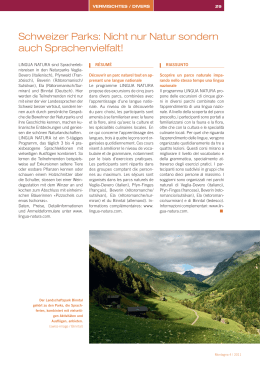
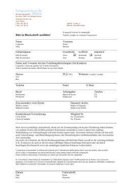
BEVP3 - BEVP4 BREVETTO N° - PATENT N. 0001314725 BARRIERA IRREVERSIBILE PER CONTROLLO TRAFFICO VEICOLARE BARRIÈRE IRRÉVERSIBLE POUR LE CONTRÔLE DU TRAFIC VÉHICULAIRE IRREVERSIBLE BARRIER TRAFFIC CONTROL SELBSTHEMMENDE VERKEHRSSTEUERUNG FOR VEHICULAR SCHRANKE ZUR BARRERA IRREVERSIBLE PARA CONTROL DE TRÁFICO VEHICULAR Operatore Operateur Operator Torantrieb Operador Alimentazione Alimentation Power Supply Stromspannung Alimentacion Lunghezza max asta Longueur maxi de la lisse Max. boom lenght Max. Baumlänge Longitud máxima de la asta codice code code code codigo BEVP3 230V/50-60Hz 3m 12007360 BEVP3 120V/60Hz 3m 12007362 BEVP4 230V/50-60Hz 4m 12007365 BEVP4 120V/60Hz 4m 12007367 ITALIANO pag. 05 / FRANÇAIS pag. 08 / ENGLISH page 11 / DEUTSCH pag. 14 / ESPAÑOL pag. 17 6-1624824 rev. 02 25/02/2011 I F ISTRUZIONI DI SICUREZZA IMPORTANTI PER L’INSTALLAZIONE INSTRUCTIONS DE SECURITE IMPORTANTES POUR L’INSTALLATION - ATTENZIONE PER LA SICUREZZA DELLE PERSONE É IMPORTANTE CHE VENGANO SEGUITE TUTTE LE ISTRUZIONI - ATTENTION POUR LA SECURITE DES PERSONNES IL EST IMPORTANT QUE TOUTES LES INSTRUCTIONS SOIENT SUIVIES SEGUIRE TUTTE LE ISTRUZIONI DI INSTALLAZIONE SUIVRE TOUTES D’INSTALLATION 1° - Questo libretto d’istruzioni è rivolto esclusivamente a del personale specializzato che sia a conoscenza dei criteri costruttivi e dei dispositivi di protezione contro gli infortuni per i cancelli, le porte e i portoni motorizzati (attenersi alle norme e alle leggi vigenti). 2° - L’installatore dovrà rilasciare all’utente finale un libretto di istruzioni in accordo alla EN 12635. 3° - L’installatore prima di procedere con l’installazione deve prevedere l’analisi dei rischi della chiusura automatizzata finale e la messa in sicurezza dei punti pericolosi identificati (seguendo le norme EN 12453/EN 12445). 4° - Il cablaggio dei vari componenti elettrici esterni all’operatore (ad esempio fotocellule, lampeggianti, ecc.) deve essere effettuato secondo la EN 60204-1 e le modifiche a questa apportate dal punto 5.2.2 della EN 12453. 5° - L’eventuale montaggio di una pulsantiera per il comando manuale del movimento deve essere fatto posizionando la pulsantiera in modo che chi la aziona non si trovi in posizione pericolosa; inoltre si dovrà fare in modo che sia ridotto il rischio di azionamento accidentale dei pulsanti. 6° - Tenete i comandi dell’automatismo (pulsantiera, telecomando etc.) fuori dalla portata dei bambini. I comandi devono essere posti ad un’altezza minima di 1,5m dal suolo e fuori dal raggio d’azione delle parti mobili. 7° - Prima di eseguire qualsiasi operazione di installazione, regolazione, manutenzione dell’impianto, togliere la tensione agendo sull’apposito interruttore magnetotermico collegato a monte dello stesso. LES INSTRUCTIONS 1° - Ce livret d’instructions est adressé exclusivement à un personnel spécialisé qui connaît les critères de construction et les dispositifs de protection contre les accidents concernant les portails, les portes et les grandes portes motorisés (s’en tenir aux normes et aux lois en vigueur). 2° - L’installateur devra délivrer à l’utilisateur final un livret d’instruction en accord à la EN 12635. 3° - L’installateur avant de procéder à l’installation, doit prévoir l’analyse des risques de la fermeture automatisée finale et la mise en sécurité des points identifiés dangereux (en suivant les normes EN 12453/EN 12445). 4° - Le câblage des divers composants électriques externes à l’opérateur (par exemple photocellules, clignotants, etc) doit être effectué selon la EN 60204-1 et les modifications apportées à celle-ci dans le point 5.2.2 de la EN 12453. 5° - Le montage éventuel d’un tableau pour la commande manuelle du mouvement doit être fait en positionnant le tableau de façon à ce que la personne qui l’actionne ne se trouve pas en position de danger ; de plus, il faudra faire en sorte que le risque d’actionnement accidentel des boutons soit réduit. 6° - Tenir les commandes de l’automatisme (tableau, télécommande, etc) hors de portée des enfants. Les commandes doivent être placées à une hauteur minimum de 1,5 m du sol et hors du rayon d’action des parties mobiles. 7° - Avant l’exécution de toute opération d’installation, de réglage, d’entretien de l’installation, couper le courant en agissant sur l’interrupteur magnétothermique à cet effet, branché en amont de l’installation. LA DITTA ALLMATIC NON ACCETTA NESSUNA RESPONSABILITÀ per eventuali danni provocati dalla mancata osservanza nell’installazione delle norme di sicurezza e delle leggi attualmente in vigore. LA SOCIETE ALLMATIC N’ACCEPTE AUCUNE RESPONSABILITE pour d’éventuels dommages provoqués par la non-observation dans l’installation, des normes de sécurité et des lois actuellement en vigueur. CONSERVARE CON CURA QUESTE ISTRUZIONI CONSERVER SOIGNEUSEMENT CES INSTRUCTIONS 1° - S e non é previsto nella centralina elettrica, installare a monte della medesima un’interruttore di tipo magnetotermico (onnipolare con apertura minima dei contatti pari a 3mm) che riporti un marchio di conformità alle normative internazionali. Tale dispositivo deve essere protetto contro la richiusura accidentale (ad esempio installandolo dentro quadro chiuso a chiave). 2° - Per la sezione ed il tipo dei cavi ALLMATIC consiglia di utilizzare un cavo di tipo H05RN-F con sezione minima di 1,5mm2 e comunque di attenersi alla norma IEC 364 e alle norme di installazione vigenti nel proprio Paese. 3° - Posizionamento di un’eventuale coppia di fotocellule: Il raggio delle fotocellule deve essere ad un’altezza di 50÷60 cm dal suolo e ad una distanza dal piano di movimento dell’asta non superiore a 15 cm. Il loro corretto funzionamento deve essere verificato a fine installazione in accordo al punto 7.2.3 della EN 12445. 1° - Si ce n’est pas prévu dans la centrale électrique, installer en amont de celle-ci un interrupteur de type magnéto-thermique (omnipolaire avec ouverture minimum des contacts égale à 3 mm) qui porte la marque de conformité aux normes internationales. Ce dispositif doit être protégé contre la re-fermeture accidentelle (par exemple en l’installant dans un cadre fermé à clé). 2° - Pour la section et le type des câbles, ALLMATIC conseille d’utiliser un câble de type H05RN-F ayant une section minimum de 1,5mm2 et de toute façon s’en tenir à la norme IEC 364 et aux normes d’installation en vigueur dans le propre pays. 3° - Positionnement d’un couple éventuel de photocellules : Le rayon des photocellules doit être à une hauteur de 50÷60 cm du sol et à une distance du plan de mouvement de la lisse qui ne soit pas supérieure à 15 cm. Leur bon fonctionnement doit être vérifié en fin d’installation en accord avec le point 7.2.3 de la EN 12445. N.B.: É obbligatoria la messa a terra dell’impianto I dati descritti nel presente manuale sono puramente indicativi. ALLMATIC si riserva di modificarli in qualsiasi momento. Realizzare l’impianto in ottemperanza alle norme ed alle leggi vigenti. N.B.: Il est obligatoire d’avoir la prise de terre pour l’installation. Les données décrites dans ce manuel sont purement indicatives. ALLMATIC se réserve le droit de les modifier à n’importe quel moment. Réaliser l’installation conformément aux normes et aux lois en vigueur. 6-1624824 rev. 02 25/02/2011 2 G B D IMPORTANT SAFETY INSTRUCTIONS FOR THE INSTALLATION - ATTENTION FOR THE SAFETY OF THE PEOPLE IT IS IMPORTANT TO FOLLOW ALL THE INSTRUCTIONS. WICHTIGE SICHERHEITS ANLEITUNGEN FÜR DIE INSTALLATIONEN - ACHTUNG FÜR DIE SICHERHEIT DER PERSONEN IST ES WICHTIG, DASS ALLE ANWEISUNGEN GENAU AUSGEFÜHRT WERDEN FOLLOW ALL INSTALLATION INSTRUCTIONS ALLE INSTALLATIONSANLEITUNGEN BEFOLGEN 1° - This handbook is exclusively addressed to the specialized personnel who knows the constructive criteria and the protection devices against the accidents for motorized gates, doors and main doors (follow the standards and the laws in force). 2° - The installer will have to issue to the final user a handbook in accordance with the EN 12635. 3° - Before proceeding with the installation, the installer must forecast the risks analysis of the final automatized closing and the safety of the identified dangerous points (following the standards EN 12453/EN 12445). 4° - The wiring harness of the different electric components external to the operator (for example photoelectric cells, flashlights etc.) must be carried out according to the EN 60204-1 and the modifications to it done in the point 5.2.2 of the EN 12453. 5° - The possible assembly of a keyboard for the manual control of the movement must be done by positioning the keyboard so that the person operating it does not find himself in a dangerous position; moreover, the risk of accidental activation of the buttons must be reduced. 6° - Keep the automatism controls (push-button panel, remote control etc.) out of the children way. The controls must be placed at a minimum height of 1,5m from the ground and outside the range of the mobile parts. 7° - Before carrying out any installation, regulation or maintenance operation of the system, take off the voltage by operating on the special magnetothermic switch connected upstream it. 1° - D iese Betriebsanleitung dient ausschließlich dem Fachpersonal, welche die Konstruktionskriterien und die Sicherheits-Vorschriften gegen Unfälle für Tore, Türen und automatische Tore kennt (geltende Normen und Gesetze beachten und befolgen). 2° - Der Monteur muss dem Endkunde eine Betriebsanleitung in Übereinkunft der EN12635 überreichen. 3° - Vor der Installierung muss für die automatische Schließung und zur Sicherheitsgewährung der identifizierten kritischen Punkte, eine Risiko Analyse vorgenommen werden mit der entsprechenden Behebung der identifizierten, gefährlichen Punkte. (die Normen EN 12453/EN 12445 befolgend). 4° - Die Verkabelung der verschiedenen externen elektrischen Komponenten zum Operator (z.B. Fotozellen, Blinker etc.) muss nach EN 60204-1 ausgeführt werden, Änderungen davon nach Punkt 5.2.2 der EN 12453. 5° - Die eventuelle Montage einer Schalttafel für den manuellen Bewegungsbefehl muss so angebracht werden, dass der Benutzer sich nicht in einer Gefahrenzone befindet, und dass, das Risiko einer zufälligen nicht gewollten Aktivierung von Schaltern gering ist. 6° - Alle Steuerungselemente (Schalttafel, Fernbedienung etc.) gehören nicht in Reichweite von Kindern. Die Kommandos müssen min. 1,5 m ab Boden und außerhalb des Aktionsbereiches der mobilen Teile angebracht werden. 7° - Vor jeglichem Eingriff, sei es Installation, Regulation oder Wartung der Anlage, muss vorher die Stromzufuhr unterbrochen werden, den dafür bestimmten MagnetthermoSchalter drücken, der am Eingang der Anlage installiert ist. THE ALLMATIC COMPANY DOES NOT ACCEPT ANY RESPONSIBILITY for possible damages caused by the non observance during the installation of the safety standards and of the laws in force at present. DIE FIRMA ALLMATIC ÜBERNIMMT KEINE VERANTWORTUNG für eventuelle Schäden, die entstehen können, wenn die Installierungsvorschriften die den gültigen Sicherheitsnormen entsprechen, nicht eingehalten werden. KEEP THESE INSTRUCTIONS WITH CARE INSTALLATIONSVORSCHRIFTEN BEACHTET WERDEN 1° - If it is not forecast in the electric gearcase, install a switch of magnetothermic type upstream, (omni polar with minimum port of the contacts of 3mm) with a check of conformity to the international standards. Such devise must be protected against the accidental lockup (for example by installing inside a locked board). 2° - For the section and the type of the cables, ALLMATIC advices to use a cable of the H05RN-F type with minimum section of 1,5sqmm and, in any case, to keep to the IEC 364 standard and to the installation standards in force in your country. 3° - Positioning of a possible couple of photoelectric cells: the radius of the photoelectric cells must be at a height of 50÷60 cm from the ground and at a distance not superior to 15 cm from the motion plane of the rod. Their correct working must be verified at the end of the installation in accordance with the point 7.2.3 of the EN 12445. 1° - W enn in der elektrischen Steuerung nicht vorgesehen, muss am Eingang derselben ein Schalter angebracht werden des Typs thermomagnetisch (mit minimaler Öffnung der Kontakte bzw. 3mm), welcher die Übereinstimmungszeichen der internationalen Normen aufweist. Diese Vorrichtung muss geschützt werden vor einer ungewollten Schließung (z.B. wenn sie in einer abgeschlossenen Schalttafel installiert ist). 2° - Für die Sektion und für den Kabel-Typ empfiehlt ALLMATIC die Benutzung eines Kabels des Typs H05RN-F mit Minimalsektion von 1,5mm2 und auf jeden Fall, sich an die Norm IEC 364 halten, unter Beachtung der gültigen Installationsnormen des eigenen Landes. 3° - Positionierung eines eventuellen Fotozellen Paares: Der Fotozellenstrahl muss auf einer Höhe von 50 – 60 cm. vom Boden angebracht werden, die Distanz zu der Bewegungsfläche der Schranke darf nicht mehr als 15 cm sein. Ihre korrekte Funktionierung muss bei Installationsschluss überprüft werden, in Übereinstimmung mit Punkt 7.2.3 der EN 12445. N.B.: The earthing of the system is obligatory. The data described in this handbook are purely a guide. ALLMATIC reserves the right to change them in any moment. Carry out the system in the respect of the standards and laws in force. 6-1624824 rev. 02 25/02/2011 N.B. Die Erdung der Anlage ist obligatorisch. Die beschriebenen Daten in der vorliegenden Betriebsanleitung sind rein indikativ. ALLMATIC behält sich vor, diese in jedem Moment zu modifizieren. Die Anlage einbauen unter Beachtung der geltenden Normen und Gesetze. 3 E S IMPORTANTES INSTRUCCIONES DE SEGURIDAD PARA LA INSTALACIÓN - CUIDADO UNA INCORRECTA INSTALACIÓN PUEDE CAUSAR GRAVES DAÑOS SEGUIR TODAS LAS INSTRUCCIONES DE INSTALACIÓN 1° - E ste manual de instrucciones está exclusivamente dirigido a personal especializado que conozca los criterios de construcción y de los dispositivos de protección contra accidentes con cancelas, puertas y portales motorizados (atenerse a las normas y a las leyes vigentes). 2° - El instalador tendrá que dar al utilizador final un manual de instrucciones de acuerdo con la EN 12635. 3° - El instalador antes de proceder con la instalación tiene que hacer una analisis de los riesgos del cierre automatizado final y la puesta en seguridad de los puntos identificados como peligrosos (siguiendo las normas EN 12453 / EN 12445). 4° - El cablaje de los varios componentes eléctricos externos al operador (por ejemplo fotocélulas, los intermitentes, etc) tiene que ser efectuado según la EN 60204-1 y a las modificas sucesivas aportadas por el punto 5.2.2 della EN 12453. 5° - El eventual montaje de un panel de mandos para la gestión del movimiento manual tiene que ser efectuado posicionando el panel en modo que quién lo accione no se encuentre en una posición peligrosa; además se tiene que hacer en modo que el riesgo de accionamiento accidental de los pulsadores sea mínimo. 6° - Tener los mandos del automatismo (panel de mandos, mando a distancia, etc.) lejos del alcance de los niños. Los mandos tienen que ser puestoa una altura mínima de 1,5m del suelo y fuera del radio de acción de las partes móviles. 7° - Antes de ejecutar cualquier operación de instalación, ajuste o mantenimiento del sistema, quitar la corriente accionando el respectivo interruptor magnetotérmico conectado antes del mismo. LA EMPRESA ALLMATIC NO ES RESPONSABLE por eventuales daños provocados por la falta de respeto de las normas de seguridad, durante la instalación y de las leyes actualmente vigentes. CONSERVAR CUIDADOSAMENTE ESTAS INSTRUCCIONES 1° - E n el caso de que no sea previsto en la central eléctrica, instalar antes de la misma, un interruptor de tipo magnetotérmico (omnipolar con una abertura mínima de los contactos de 3mm) que dé un sello de conformidad con las normas internacionales. Este dispositivo tiene que estar protegido contra cierres accidentales (por ejemplo instalándolo dentro de un panel cerrado a llave). 2° - Para la sección y el tipo de los cables, ALLMATIC aconseja utilizar cables de tipo H05RN-F con sección mínima de 1,5mm2 e igualmente atenerse a la norma IEC 364 y a las normas de instalación del propio País. 3° - Posicionamiento eventual de un par de fotocélulas. El rayo de las fotocélulas no debe estar a más de 70 cm de altura desde el suelo y a una distancia de la superficie de movimiento de la puerta, no superior a 20 cm. El correcto funcionamiento tiene que ser controlado al final de la instalación de acuerdo con el punto 7.2.1 de la EN 12445. PS.: Es obligatorio la puesta a tierra del sistema. Los datos descritos en el presente manual son sólamente indicativos. ALLMATIC se reserva de modificarlos en cualquier momento. Realizar el sistema respetando las normas y las leyes vigentes. 6-1624824 rev. 02 25/02/2011 4 I LAYOUT IMPIANTO CARATTERISTICHE TECNICHE 270 Serie di operatori irreversibili utilizzati per movimentare aste lunghe 3 o 4 m. Vengono forniti completi di piastra da cementare, centralina elettronica di comando, molle di bilanciamento già regolate, Encoder per rilevamento ostacoli e asta telescopica lunga 3 o 4 m. N.B. È obbligatorio uniformare le caratteristiche dell’impianto alle norme e leggi vigenti. 959 353 3000-4000 600 SICUREZZE ELETTRICHE Ø220 170 Nella BEVP il motore e l’encoder sono già collegati al quadro elettronico di comando incorporato. Sono da collegare solamente i fili di una pulsantiera e, naturalmente, della tensione di alimentazione. Per i collegamenti ed i dati tecnici degli accessori attenersi ai relativi libretti di istruzione. 302 Barriera BEVP Fotocellule Colonnina porta fotocellula Sensore magnetico - Selettore a chiave - Antenna radio 6-1624824 rev. 02 25/02/2011 5 I CARATTERISTICHE TECNICHE BEVP3 - BEVP4 Lunghezza max. asta m 3 4 Tempo di apertura s 3 3,5 Coppia sull’albero porta asta Nm 100 130 Alimentazione e frequenza 230V~ 50/60Hz Potenza W 74 Assorbimento A 0,320 Alimentazione e frequenza Potenza W 72 Assorbimento A 0,6 Cicli normativi N° ∞ - 3s/2s Cicli consigliati al giorno N° 600 Servizio Cicli consecutivi garantiti N° Peso max kg 40 Temperatura di lavoro °C -10 ÷ +55 Grado di protezione IP 44 120V~ 60Hz TIPO DI COMANDO a uomo presente a impulsi in vista (es. sensore) a impulsi non in vista (es. telecomando) automatico USO DELLA CHIUSURA Persone esperte Persone esperte (fuori da area pubblica*) (area pubblica) A B C C C C e D C e D C e D Uso illimitato CeD CeD CeD * esempio tipico sono le chiusure che non accedono alla pubblica via. A: Pulsante di comando a uomo presente (cioè ad azione mantenuta). B: Selettore a chiave a uomo presente. C: Encoder incorporato (in funzione di dispositivo di limitazione delle forze entro i limiti della norma EN12453 - Appendice A). D: Encoder incorporato (in funzione di rilevatore di presenza). 100% 600 Componenti da installare secondo la norma EN12453 400 MONTAGGIO DELLA BEVP ASSEMBLAGGIO PIASTRA DA CEMENTARE ASSEMBLAGGIO ASTA TELESCOPICA da 3 m -A vvitare le 4 barre ripiegate alla piastra da cementare utilizzando le rondelle ed i dadi in dotazione con una chiave esagonale n° 19 come da Fig. 1-2. ATTENZIONE : Posizionare la piastra da cementare facendo attenzione che sia perfettamente in piano e che il segno a punta sia rivolto nella direzione esatta dove si vuole che scenda l’asta. - Una volta cementata la piastra, avvitate le 3 barre filettate lunghe serrandole con forza con una pinza come da Fig. 3-4-5-6. -P rocedere all’assemblaggio dell’asta telescopica inserendo i tre tubi uno dentro all’altro fino a far combaciare i fori (Fig. 21-22). - Bloccate il tubolare Ø 60 a quello Ø 55 usando la vite passante da TCEI 6x70 unitamente alle 2 rondelle ed al dado autobloccante. Per far ciò usate una chiave a brugola n°5 ed una chiave esagonale n°10. - Bloccate il secondo tubolare al terzo tubolare usando le viti e rondelle dentellate in dotazione ed inserite i tappi in punta all’asta (Fig. 23). Nota: In caso vogliate accorciare la lunghezza dell’asta NON TAGLIATELA NÈ RIMUOVETE UNO DEI TUBOLARI. Fate semplicemente scorrere il tubolare in punta all’asta all’interno del tubolare di mezzo fino ad ottenere la lunghezza d’asta desiderata e ribloccatelo usando le viti in dotazione. Naturalmente per far ciò dovete forare il tubolare in punta con una punta Ø 5 e filettare con un maschio da M6 per creare le nuove sedi per le viti in dotazione. Potete accorciare l’asta fino a 2 m senza dover ribilanciare l’asta. ASSEMBLAGGIO COLONNA DI SUPPORTO OPERATORE -D opo aver avvitato le barre ed aver tirato i cavi elettrici per i collegamenti, inserite il tubo CCA1289 ed appoggiate sopra ad esso la piastra di supporto dell’operatore CCA1281. Tirate i cavi elettrici fin sopra la piastra di supporto dell’operatore come da Fig. 7-8-9. - Avvitate la piastra di supporto con le rondelle ed i dadi in dotazione con una chiave esagonale n° 17 come da Fig. 10-11-12. ASSEMBLAGGIO ASTA TELESCOPICA da 4 m FISSAGGIO OPERATORE SU COLONNA -P rocedere all’assemblaggio dell’asta telescopica inserendo i 4 tubi uno dentro all’altro fino a far combaciare i fori (Fig. 21-22). - Bloccate il tubolare Ø 60 a quello Ø 55 usando la vite passante da TCEI 6x70 unitamente alle 2 rondelle ed al dado autobloccante. - Inserite i successivi tubolari bloccandoli tra loro usando le ulteriori rimanenti viti TCEI 6x60, dadi e rondelle in dotazione (Fig. 23). Per far ciò usate una chiave a brugola n° 5 ed una chiave esagonale n° 10. - Inserite i tappi in punta all’asta. -A ppoggiate l’operatore sopra la piastra di supporto e fissatelo stringendo con una chiave a brugola n° 6 le 4 viti a testa svasata in dotazione come da Fig. 13-14-15. RIMOZIONE MOZZO PORTA ASTA DA OPERATORE -R imuovete con una chiave a brugola n° 5 il cappellotto coprimozzo (Fig. 16). - Rimuovete la piastra di sicurezza svitando le 4 viti con una chiave esagonale n° 10 (Fig. 17-18). - Svitate le due viti che fermano il mozzo con una chiave a brugola n° 8 e rimuovetelo dall’operatore (Fig. 19-20). 6-1624824 rev. 02 25/02/2011 Nota: In caso vogliate accorciare la lunghezza dell’asta NON TAGLIATELA NÈ RIMUOVETE UNO DEI TUBOLARI. Fate semplicemente scorrere il tubolare in punta all’asta all’interno del tubolare che lo precede fino ad ottenere la lunghezza d’asta desiderata 6 I e ribloccatelo usando le viti in dotazione. Naturalmente per far ciò dovete forare il tubolare in punta con una punta Ø 6, 5. Potete accorciare l’asta fino a 3,5 m senza dover ribilanciare l’asta. Se volete che l’asta abbia una misura compresa tra 3 e 3,49 m dovete ribilanciare l’asta. cod. BA10096 M otoriduttore BEVP 3 m + Coppia molle di bilanciamento (con istruzioni per la sostituzione e la regolazione) cod. BA10097 Motoriduttore BEVP 4 m + Coppia molle di bilanciamento (con istruzioni per la sostituzione e la regolazione) cod. BA10098 “Testa” BEVP 3 m (con molle già bilanciate) cod. BA10099 “Testa” BEVP 4 m (con molle già bilanciate) ASSEMBLAGGIO ASTA NEL MOZZO PORTA ASTA N.B.: In caso di rottura accidentale delle sole molle prima del previsto intervallo di manutenzione potete richiederle utilizzando il codice: cod. BA10095 Coppia molle di bilanciamento (con istruzioni per la sostituzione e la regolazione) - Infilate l’asta dalla parte col diametro maggiore nel mozzo (Fig. 24). ATTENZIONE: Ruotate l’asta nel mozzo in modo che le viti siano perpendicolari alla piastra del mozzo (Fig. 25). - Bloccate l’asta nel mozzo strigendo le due viti con una chiave esagonale n° 10 (Fig. 26). ATTENZIONE La non sostituzione del gruppo primario CMO1330 al termine dei cicli indicati comporta la cancellazione immediata della garanzia. Applicare cartelli o altri tipi di peso sull’asta in dotazione comporta una riduzione della vita dell’operatore e la cancellazione immediata della garanzia. Applicare aste diverse dal modello ALLMATIC comporta la cancellazione immediata della garanzia. INSERIMENTO MOZZO CON ASTA SU OPERATORE -M ontate il mozzo con l’asta in posizione verticale sull’albero dell’operatore e bloccatelo stringendo le 2 viti in dotazione con una chiave a brugola n° 8 (Fig. 27-28). REGOLAZIONE DELLA POSIZIONE DELL’ASTA -S e l’asta non risulta perfettamente orizzontale potete posizionare una livella sull’asta e, dopo avere allentato le due viti di regolazione dell’asta, alzare o abbassare l’asta a volontà. Una volta determinata la posizione voluta serrate le due viti di regolazione dell’asta (Fig. 30). - Applicare la piastra di sicurezza sul mozzo e bloccarla con le 4 viti in dotazione (Fig. 31-32-33). - Rimontare il cappellotto copri mozzo (Fig. 34-35). - A montaggio ultimato le viti di serraggio dei profili delle aste devono essere visibili come da figura 36. ATTENZIONE: NON AZIONARE ELETTRICAMENTE L’OPERATORE SE L’ASTA NON È STATA ANCORA MONTATA. ATTENZIONE: NON APPLICARE ALL’ASTA PESI ADDIZIONALI NON FACENTI PARTE DEL PRODOTTO QUALI CARTELLI, LUCI, RASTRELLIERE, COSTE, ECC. ATTENZIONE: NON UTILIZZARE PALETTI PER IL SOSTEGNO DELL’ASTA MONTATI SULL’ASTA O A TERRA. SBLOCCO DI EMERGENZA Da effettuare dopo aver tolto l’alimentazione elettrica al motore. In caso di mancanza di corrente, per poter aprire manualmente la sbarra è necessario sbloccare l’operatore. Per far ciò, mentre si preme con una mano l’asta verso il basso, si utilizza la chiave in dotazione e la si gira manualmente in senso antiorario per 4 volte (Fig. 37). In questo modo l’asta della barriera è indipendente dall’operatore, ma non dalle molle di bilanciamento, e la si può muovere manualmente. Una volta tornata la corrente si abbassa l’asta e si gira la chiave in senso orario fino al fermo. ATTENZIONE: Se si riblocca l’asta a sbarra alzata il primo comando sarà comunque di apertura e non si vedrà il movimento della barriera. Al secondo comando la sbarra chiuderà. MANUTENZIONE Da effettuare solamente da parte di personale specializzato dopo aver tolto l’alimentazione elettrica al motore. Ogni 100.000 cicli verificare che le due viti di fermo della regolazione del mozzo porta asta siano fermamente bloccate. Ogni 200.000 cicli dovete sostituire il gruppo motoriduttore primario e la coppia di molle di bilanciamento o per vostra maggiore praticità l’intera “testa” della barriera BEVP 4 m. Ogni 500.000 cicli dovete sostituire il gruppo motoriduttore primario e la coppia di molle di bilanciamento o per vostra maggiore praticità l’intera “testa” della barriera BEVP 3 m. 6-1624824 rev. 02 25/02/2011 7 SCHÉMA DÉTAILLÉ DE L’INSTALLATION CARACTERISTIQUES TECHNIQUES BEVP 270 Série d’opérateurs irréversibles utilisés pour déplacer des tiges d’une longueur de 3 ou 4 m. Ils sont fournis avec une plaque à cimenter, une centrale électronique de commande, des ressorts d’équilibrage déjà réglés, un Encodeur pour relever les obstacles et une tige télescopique d’une longueur de 3 ou 4 m. N.B. Il est obligatoire d’uniformiser les caractéristiques de l’installation aux normes et aux lois en vigueur. 959 353 3000-4000 600 SECURITES ELECTRIQUES Ø220 Dans la BEVP, le moteur et l’encodeur sont déjà branchés au coffret électrique de commande incorporé. Il faut seulement brancher les fils d’un bouton poussoir et naturellement de la tension d’alimentation. Pour les branchements et les données techniques des accessoires, se conformer aux livrets d’instruction correspondants. 170 F 302 Barrière BEVP Photocellules Colonne porte-photocellule Détecteur magnétique - Sélecteur à clef - Antenne radio 6-1624824 rev. 02 25/02/2011 8 F CARACTÉRISTIQUES TECHNIQUES BEVP3 - BEVP4 Longueur maxi de la lisse m 3 4 Temps d’ouverture s 3 3,5 Couple maxi arbre sortie Nm 100 130 Alimentation et frequence 230V~ 50/60Hz Puissance moteur W 74 Absorption A 0,320 Alimentation et frequence Puissance moteur W 72 Absorption A 0,6 Cycles normatifs N° ∞ - 3s/2s Cycles conseillés par jour N° 600 Service Cycles consécutifs garantis 400 Poids maximun kg 40 Température de travail °C -10 ÷ +55 Indìce de protection IP 44 Composants à installer selon la norme EN12453 120V~ 60Hz TYPE DE COMMANDE à pression maintenue (Homme mort) à impulsions à vue (ex. Détecteur) à impulsions non à vue (ex. télécommande) automatique USAGE DE LA FERMETURE Personnes expertes Personnes expertes (au dehors d’une zone publique*) (zone publique) A B C C C C et D C et D C et D Usage illimité C et D C et D C et D * l’exemple typique sont les fermetures qui n’accèdent pas à un chemin public. A: Touche de commande à homme present (à action maintenue). B: Sélecteur à clef avec homme présent. C: Encodeur incorporé (en fonction du dispositif de limitation des forces dans les limites de la norme EN12453 - Appendice A). D: Encodeur incorporé (en fonction du releveur de présence). 100% 600 °N MONTAGE DE BEVP ASSEMBLAGE PLAQUE A SCELLER ASSEMBLAGE TIGE TELESCOPIQUE de 3 m ASSEMBLAGE COLONNE DE SUPPORT OPERATEUR Nota: Si vous vouliez raccourcir la longueur de la tige, NE LA COUPEZ PAS ET NE RETIREZ PAS UN DES TUBES. Faire simplement glisser le tube en pointe de la tige à l’intérieur du tube du milieu jusqu’à obtention de la longueur de tige désirée et le re-bloquer en utilisant les vis fournies. Naturellement, pour faire cela, il faut faire un trou dans le tube en pointe avec une pointe de Ø 5 et fileter avec un mâle de M6 pour créer les nouveaux logements pour les vis fournies. Il est possible de raccourcir la tige jusqu’à 2 m sans devoir rééquilibrer la tige. -V isser avec une clé Allen n° 19, les 4 goujons repliés à la plaque à sceller en utilisant les rondelles et les écrous fournis comme Fig. 1-2. ATTENTION: Positionner la plaque à sceller en faisant attention à ce qu’elle soit parfaitement à niveau et en faisant attention à ce que le signe en forme de pointe soit tourné dans la direction, là où l’on veut que la lisse descende. - Une fois la plaque cimentée, visser les 3 longues tiges filetées en les serrant fortement avec une pince comme Fig. 3-4-5-6. -P rocéder à l’assemblage de la tige télescopique en insérant les trois tubes l’un dans l’autre jusqu’à faire coïncider les trous (Fig. 21-22). - Bloquer le tube Ø60 à celui Ø 55 en utilisant le goujon de TCEI 6x70 avec les 2 rondelles et l’écrou de sécurité. Pour cela, utiliser un clef six-pans mâle n° 5 et une clef hexagonale n° 10. - Bloquer le deuxième tube au troisième tube en utilisant les vis et rondelles fournies et insérer les bouchons en pointe sur la tige (Fig. 23). -A près avoir vissé les tiges et après avoir tiré les câbles électriques pour les branchements, insérer le tube CCA1289 et poser dessus la plaque de support de l’opérateur CCA1281.Tirer les câbles électriques jusqu’au-dessus de la plaque de support de l’opérateur comme Fig. 7-8-9. - Visser avec une clé Allen n° 17, la plaque de support avec les rondelles et les écrous fournis comme Fig. 10-11-12. ASSEMBLAGE TIGE TELESCOPIQUE de 4 m FIXATION OPERATEUR SUR COLONNE -P rocéder à l’assemblage de la tige télescopique en insérant les 4 tubes l’un dans l’autre jusqu’à faire coïncider les trous (Fig. 21-22). - Bloquer le tube Ø 60 à celui Ø 55 en utilisant le goujon de TCEI 6x70 avec les 2 rondelles et l’écrou de sécurité. - Bloquer les tubes suivants en les bloquant entre eux en utilisant les vis TCEI 6x60, écrous et rondelles fournies (Fig. 23). Pour cela, utiliser un clef six-pans mâle n° 5 et une clef hexagonale n° 10. - Insérer les bouchons en pointe sur la tige. -P oser l’opérateur sur la plaque de support et le fixer en serrant, avec une clé Allen n° 6, les 4 vis à tête fraisées fournies comme Fig. 13-14-15. RETRAIT DU MOYEU PORTE-LISSE DE L’OPERATEUR - Retirer avec une clé Allen n° 5 le cache protège-moyeu (Fig16). - Retirer la plaque de sécurité en dévissant les 4 vis avec une clé Allen n° 10 (Fig. 17-18). - Dévisser les deux vis qui bloquent le moyeu avec une clé Allen n° 8 et retirer le moyeu de l’opérateur (Fig. 19-20). 6-1624824 rev. 02 25/02/2011 Nota: Si vous vouliez raccourcir la longueur de la tige, NE LA COUPEZ PAS ET NE RETIREZ PAS UN DES TUBES. Faire simplement glisser 9 F le tube en pointe de la tige à l’intérieur du tube qui le précède jusqu’à obtention de la longueur de tige désirée et le re-bloquer en utilisant les vis fournies. Naturellement, pour faire cela, il faut faire un trou dans le tube en pointe avec une pointe de Ø 6, 5. Il est possible de raccourcir la tige jusqu’à 3,5 m sans devoir rééquilibrer la tige. Si vous voulez que la tige ait une longueur comprise entre 3 et 3,49 m, vous devez rééquilibrer la tige. moyeu porte tige soient bien serrées. Tous les 200.000 cycles, v ous devez substituer le groupe motoréducteur primaire et le couple de ressorts d’équilibrage ou par facilité, toute la “tête” de la barrière BEVP 4 m. Tous les 500.000 cycles, vous devez substituer le groupe motoréducteur primaire et le couple de ressorts d’équilibrage ou par facilité, toute la “tête” de la barrière BEVP 3 m. code BA10096 Motoréducteur BEVP 3 m + Couple ressort d’équilibrage (avec instructions pour la substitution et le réglage) code BA10097 Motoréducteur BEVP 4 m + Couple ressorts d’équilibrage (avec instructions pour la substitution et le réglage) code BA10098 “Tête” BEVP 3 m (avec ressorts déjà équilibrés) code BA10099 “Tête” BEVP 4 m (avec ressorts déjà équilibrés) ASSEMBLAGE LISSE DANS LE MOYEU PORTE-LISSE -E nfiler la lisse par le bout qui a le plus grand diamètre, dans le moyeu (Fig. 24). ATTENTION: Tourner la lisse dans le moyeu de façon à ce que les vis soient perpendiculaires à la plaque du moyeu (Fig. 25). - Bloquer la lisse dans le moyeu en serrant les deux vis avec une clé Allen n° 10 (Fig. 26). N.B.: En cas de rupture accidentelle des seuls ressorts avant l’intervalle d’entretien prévu, vous pouvez les demander en utilisant le code : code BA10095 Couple de ressorts d’équilibrage (avec instructions pour la substitution et le réglage). INSERTION DU MOYEU AVEC LISSE SUR OPERATEUR -M onter le moyeu avec la lisse en position verticale sur l’arbre de l’opérateur et le bloquer en serrant les deux vis fournies avec une clé Allen n° 8 (Fig. 27-28). ATTENTION La non substitution du groupe primaire CMO1330 à la fin des cycles indiqués comporte l’annulation immédiate de la garantie. Appliquer des panneaux ou autres types de poids sur la lisse fournie comporte une réduction de la vie de l’opérateur et l’annulation immédiate de la garantie. Appliquer des lisses différentes du modèle ALLMATIC comporte l’annulation immédiate de la garantie. REGLAGE DE LA POSITION DE LA TIGE -S i la tige n’est pas parfaitement horizontale, vous pouvez positionner un niveau sur la tige et, après avoir desserré les deux vis de réglage de la tige, lever ou baisser la tige à volonté. Une fois la position voulue déterminée, serrer les deux vis de réglage de la tige (Fig. 30). - Mettre la plaque de sécurité sur le moyeu et la bloquer avec les 4 vis fournies (Fig. 31-32-33). - Remonter le cache protège-moyeu (Fig. 34-35). - Une fois le montage terminé, les vis de serrage des profils des lisses doivent être visibles comme sur la figure 36. ATTENTION: N E PAS ACTIONNER ELECTRIQUEMENT L’OPERATEUR SI LA LISSE N’A PAS ENCORE ETE MONTEE. ATTENTION: NE PAS APPLIQUER A LA LISSE DES POIDS EN PLUS QUI NE FONT PAS PARTIE DU PRODUIT TELS QUE PANNEAUX, LUMIERES, RIDELLES, CORDON PALPEUR, ETC. ATTENTION: NE PAS UTILISER DE FOURCHE DE SUPPORT DE LISSE FIXE OU ESCAMOTABLE. DEBLOCAGE URGENCE A effectuer après avoir couper l’alimentation électrique au moteur. En cas de panne de courant, pour pouvoir ouvrir manuellement la barrière, il est nécessaire de débloquer l’opérateur. Pour ce faire, alors que vous appuyez sur la lisse vers le bas avec une main, utilisez la clé fournie et tournez-la manuellement quatre fois dans le sens contraire des aiguilles d’une montre (Fig. 37). De cette manière, la lisse de la barrière est decouplée de l’opérateur mais pas des ressorts d’équilibrage et il est donc possible de la manouvrer manuellement. Un fois le courant revenu, baisser la lisse et tourner la clé dans le sens des aiguilles d’une montre jusqu’à la butée. ATTENTION: Si la lisse est rembrayée quand la barrière est levée, la première commande sera de toute façon l’ouverture et le mouvement de la barrière ne se verra pas. A la deuxième commande, la barrière se fermera. ENTRETIEN Doit seulement être effectué par un personnel spécialisé après avoir coupé l’alimentation électrique au moteur. Tous les 100.000 cycles, vérifier que les deux vis d’arrêt de réglage du 6-1624824 rev. 02 25/02/2011 10 G B SYSTEM LAYOUT BEVP TECHNICAL FEATURES 270 Family of non reversible actuators to be used for operation of rods 3 or 4 m lenght. Supplied complete with foundation plate, electronic control unit, pre-set balancing springs, Encoder for obstacle detection and telescopic rod 3 or 4 m long. NOTE: Installation design will comply with the specifications and rules in force. 959 353 3000-4000 600 ELECTRIC SECURITIES In the BEVP the motor and the encoder are already connected to the incorporated control electronic board. You just need to connect the wires of a keyboard and, of course, of the feeding tension. For the connections and the technical data of the fixtures follow the relevant handbooks. 170 Ø220 302 BEVP barrier Photoelectric cells P hotoelectric cell rack column Magnetic sensor - Key selector - Aerial 6-1624824 rev. 02 25/02/2011 11 G B TECHNICAL DATA BEVP3 - BEVP4 Max. boom lenght m 3 4 Opening time s 3 3,5 Max. torque Nm 100 130 Power supply 230V~ 50/60Hz Capacity W 74 Power absorbed A 0,320 Power supply Capacity W 72 Power absorbed A 0,6 Normative cycles N° ∞ - 3s/2s Daily cycles suggested N° 600 Service Consecutive cycles guaranteed N° Actuator weight kg 40 Operating Temperature °C -10 ÷ +55 Protection grade IP 44 120V~ 60Hz COMMAND TYPE USE OF THE BARRIER Skilled persons (out of a public area*) with manned operation A with visible impulses (e.g. sensor) C with not visible impulses (e.g. remote control device) C automatic C and D Skilled persons Unrestricted use (public area) B C C and D C and D C and D C and D C and D * a typical example are those shutters which do not have access to any public way. A: Command button with manned operation (that is, operating as long as activated). B: Key selector with manned operation. C: Built-in Encoder (operating as thrust limitation device, within the limits indicated by specification EN12453 - Appendix A). D: Built-in Encoder (operating as presence detector). 100% 600 Components to install according to EN12453 standards 400 BEVP ASSEMBLY ASSEMBLY PLATE TO CEMENT ASSEMBLING OF THE 3 m TELESCOPIC BOOM -S crew down the four bars bent over the plate to cement by using the washers and the screw nuts supplied with an hexagonal setscrew wrench no. 19 as shown in figure 1-2. ATTENTION: Position the plate to cement keeping attention that it is laid down perfectly flat and that the point mark is turned towards the exact position where you want the rod to come down. - Once you have cemented the plate, screw down the three long threaded bars by clamping them energetically with a pliers as shown in figures 3-4-5-6. -A ssemble the telescopic boom fitting the three legs together, until the screws holes are aligned (Fig. 21-22). - Secure the Ø 60 leg to the Ø 55 leg with the allen screw 6x70, the two washers and the self-locking nut. Tighten by means of an allen key n° 5 and an exagonal key n° 10. - Secure the second leg to the third leg with the outfit screws and washers and insert the end caps into the boom (Fig. 23). Note: in case the rod needs to be shortened, DO NOT CUT THE ROD, NOR REMOVE A LEG. Slide the end leg into the middle leg to obtain the required overall length, and retighten by means of the outfit screws. Obviously the leg will need to be drilled Ø 5 at its end, and threaded M6 to provided new seats for the outfit screws. The rod can be shortened up to 2 m without need for balancing. ASSEMBLY OPERATOR SUPPORT COLUMN -A fter having screwed down the bars and having pulled the electric cables for the connections, insert the tube CCA1289 and lean on it the operator support plate CCA1281. Pull the electric cables up to the top of the operator support plate as shown in figures 7-8-9. - Screw down the support plate using the washers and the screw nuts supplied with a hexagonal setscrew wrench no. 17 as shown in figures 10-11-12. ASSEMBLING OF THE 4 m TELESCOPIC BOOM -A ssemble the telescopic rod fitting the 4 legs together, until the screws holes are aligned (Fig. 21-22). - Secure the Ø 60 leg to the Ø 55 leg with the allen screw 6x70, the two washers and the self-locking nut. - Insert the other legs and secure by means of the outfit screws TCEI 6x60, nuts and washers (Fig. 23). Tighten by means of an allen key n° 5 and an exagonal key n° 10. - Insert the end caps into the end leg. OPERATOR FIXING ON THE COLUMN -L ean the operator on the support plate and fix it by tightening with a socket head no. 6 the 4 screws supplied as shown in figures 13-14-15. Note: in case the rod needs to be shortened, DO NOT CUT THE ROD, NOR REMOVE A LEG. Slide the end leg into the middle leg to obtain the required overall length, and retighten by means of the outfit screws. Obviously the leg will need to be drilled Ø 6, 5. The rod can be shortened up to 3,5 m without need for balancing . In case a length ranging from 3 to 3,49 m is required, re-balancing of the rod is necessary. REMOVAL ROD RACK OPERATOR HUB - Remove the hub-cap with a screw no. 5 (Fig. 16). - Remove the security plate by screwing off the four screws with an hexagonal setscrew wrench no. 10 (Fig. 17-18). - Screw off the two screws which block the hub with a screw no. 8 and remove it from the operator (Figures 19-20). 6-1624824 rev. 02 25/02/2011 12 G B ASSEMBLY ROD IN THE ROD RACK HUB code BA10096 M otor gear BEVP 3m + Set of two balancing springs (inclusive of instructions for the replacement and setting) code BA10097 Motor gear BEVP 4m + Set of two balancing springs (inclusive of instructions for the replacement and setting) code BA10098 “Head” BEVP 3m (with pre-balanced springs) code BA10099 “Head” BEVP 4m (with pre-balanced springs) - Insert the rod from the part of the hub with the largest diameter. (Figure 24). ATTENTION : Rotate the rod in the hub so that the screws are perpendicular to the hub’s plate (Figure 25). - Fix the rod in the hub by tightening the two screws with an hexagonal setscrew no. 10 (Figure 26). NOTE: in case of seizure of the springs only, before the scheduled replacement, the items can be required with the following code: code BA10095 Set of two balancing springs (inclusive of instructions for the replacement and setting). INSERTION HUB WITH ROD ON THE OPERATOR -A ssembly vertically the hub with the rod on the shaft of the operator and fix it by tightening the two screws supplied with a socket head screw no. 8 (Figure 27-28). ATTENTION The non replacing of the primary group CMO1330 at the end of the mentioned cycles, entails the immediate deletion of the warranty. To apply placards as well as other kinds of weights on the rod supplied entails a reduction of the operator’s life and the immediate deletion of the warranty. To apply rods different by the ALLMATIC model, entails the immediate deletion of the warranty. REGULATION OF THE ROD’S POSITION - In case the rod is not thoroughly horizontal, position a bubble level onto the rod, slacken the two adjusting screws and raise or lower the rod as required. Upon correct positioning of the rod tighten the two adjusting screws (Fig. 30). - Apply the security plate on the hub and fix it with the four screws supplied (Figure 31-32-33). - Reassemble the hub cap (Figures 34-35). - Once the assembly will be completed, the clamping screws of the rods’ profiles must be visible as shown in figure 36. ATTENTION: DO NOT START ELECTRICALLY THE OPERATOR IF THE ROD HASN’T BEEN ASSEMBLED YET. ATTENTION: DO NOT APPLY ADDITIONAL WEIGHTS WHICH ARE NOT PART OF THE PRODUCT ON THE ROD, SUCH AS PLACARDS, LIGHTS, RACKS, TOOTH FACES, ETC. ATTENTION: DO NOT USE SLIDING BARS TO SUPPORT THE ROD, EITHER ASSEMBLED ON THE ROD OR ON THE GROUND. EMERGENCY RELEASE To be carried out after having removed the electric input from the motor. In case of lack of current, to open the rod manually it is necessary to release the operator. To do that, while pushing the rod downwards with a hand, use the key supplied and turn manually anticlockwise for four times (Figure 37). This way the barrier rod is independent from the operator, but not from the balance springs, and can be moved manually. Once the current is back, pull down the rod and turn the key clockwise until it stops. ATTENTION: In case the rod blocks again when the bar is up, the first command will be the opening one in any case, and you will not see the movement of the barrier. At the second command, the bar will close. MAINTENANCE To be exclusively carried out by the specialized personnel after having removed the electric input from the machine. Every 100.000 operation cycles ensure the two securing screws for the setting of the rod hub are fully tightened. Every 200.000 operation cycles replace the main motor gear and the two balancing springs. For ease of operation the whole fence “head” of BEVP 4 m can be replaced. Every 500.000 operation cycles replace the main motor gear and the two balancing springs. For ease of operation the whole fence “head” of BEVP 3 m can be replaced. 6-1624824 rev. 02 25/02/2011 13 ANLAGEN LAY-OUT BEVP - TECHNISCHE EIGENSCHAFTEN 270 Reihe von irreversiblen Operatoren, die benutzt werden, um 3 oder 4 m lange Stangen zu bewegen. Diese werden komplett geliefert, d.h. mit noch zu zementierender Platte, elektronischem Steuergerät, mit bereits eingestellter Auswuchtungsfeder, Encoder als Hindernis-Melder und 3 oder 4 m langer Teleskop-Stange. Beachten: Es ist Pflicht, die Eigenschaften der Anlage an die gültigen gesetzlichen Richtlinien und Vorschriften anzupassen. 959 353 3000-4000 600 ELEKTRISCHE SICHERHEITEN Ø220 Bei BEVP sind Motor und Encoder bereits der elektrischen eingegliederten Steuerschalttafel angeschlossen. Es müssen nur die Drähte einer Schalttafel und natürlich die Stromspannung angeschlossen werden. Für die Anschlüsse und die technischen Daten der Zubehöre verweisen wir auf die entsprechenden Betriebsanleitungen. 170 D 302 Schranke BEVP Fotozellen S äulenträger für Fotozelle Magnet-Sensor - Schlüsselschalter - Radio Antenne 6-1624824 rev. 02 25/02/2011 14 D TECHNISCHE EIGENSCHAFTEN BEVP3 - BEVP4 Max. Baumlänge m 3 4 Öffnungszeit s 3 3,5 Max. Drehmoment Nm 100 130 Stromspannung und frequenz Motorleistung W 74 Stromaufnahme A 0,320 Stromspannung und frequenz Motorleistung W 72 Stromaufnahme A 0,6 Anzahl der normative Zyklen N° ∞ - 3s/2s Zyklen rieten einem Tag N° 600 Service Garantierte nachfolgende Zyklen N° Motorgewicht kg 40 Betriebstemperatur °C -10 ÷ +55 Schutzart IP 44 230V~ 50/60Hz 120V~ 60Hz * ein Musterbeispiel dafür sind jene Türe, die keine Zufahrt zu einem öffentlichen Weg haben. A: Betriebstaste mit Totmannschaltung (das heißt, aktivieren sie eine Funktion, solange man sie gedrückt hält). B: Schlüsselselektor mit Totmannschaltung. C: Eingebauter Encoder (fungiert als Einrichtung zur Einschränkung der auswirkenden Kräfte nach Norm EN12453 - Anhang A). D: Eingebauter Encoder (als Hindernis-Melder). 100% 600 Komponenten zur Installation nach der Norm EN1253 STEUERUNGSSYSTEM ANWENDUNG DER SCHLIESSUNG Fachpersonen Fachpersonen Grenzlose (außer einem öffentlichen Platz*) (öffentlicher Platz) Anwendung mit Totmannschaltung A B mit sichtbaren Impulsen (z. B. Sensor) C C C und D mit nicht sichtbaren Impulsen (z. B. Fernsender) C C und D C und D automatisch C und D C und D C und D 400 MONTAGE DER BEVP MONTAGE DER PLATTE, ZUM EINZEMENTIEREN ZUSAMMENBAU MONTAGE -Z um Zusammenbau der Teleskop-Stange sollen die drei Rohre ineinander gesteckt werden, bis die Löcher übereinander liegen (Abb. 21-22). - Das Ø 60 an das Ø 55 Rohr mittels der TCEI 6x70 Schraube zusammen mit den 2 Unterlegscheiben und der Haltemutter befestigen. Hierbei sollen ein Inbusschlüssel Nr. 5 und ein Sechskant-Schlüssel Nr. 10 benutzt werden. - Das zweite und das dritte Rohr mit Hilfe der mitgelieferten Schrauben und Unterlegscheiben befestigen und Stöpsel am Stangenende anbringen (Abb. 23). LÄNGE -D ie 4 gebogenen Stangen sind an die Platte anzuschrauben, dabei die mitgelieferten Unterlegscheiben und Schraubenmuttern mittels Sechskant Schlüssel Nr. 19 verwenden (Fig. 1-2). ACHTUNG: Die Zementier-Platte auflegen, dabei achten dass diese ganz eben und flach liegt, und dass der Zielpunkt genau in die Richtung orientiert ist, wo man die Schranken-Sperre wünscht. - Ist die Platte zementiert, werden die drei Stangen mit Kraft ins Gewinde geschraubt. (Fig. 3-4-5-6). DER SÄULEN HALTERUNG -W enn die Stangen angeschraubt sind, und wenn die elektrischen Kabel für den Anschluss gelegt sind, das Rohr CCA1289 auf die Halter-Platte CCA1281 gelegt. Die elektrischen Kabel müssen nun über die Halter-Platte gezogen werden (Fig. 7-8-9). - Die Halter-Platte muss nun mit den Unterlegscheiben und mit den mitgelieferten Schraubenmuttern mittels eines Sechskant Schlüssels Nr. 17 angeschraubt werden. (Fig. 10-11-12). FIXIERUNG Bemerkung (falls man die Stange verkürzen möchte): Die STANGE DARF AUF KEINEN FALL DURCH ABSCHNEIDEN ODER ENTFERNEN EINES ROHRS GEKÜRZT WERDEN. Stattdessen das Endrohr in das mittlere hineinschieben, bis man die gewünschte Stangenlänge erreicht hat und dann mit den mitgelieferten Schrauben befestigen. Zu diesem Zweck muss man das Rohr mit einem Ø5 Bohrer lochen und das passende Gewinde für die mitgelieferten Schrauben mit einem M6-Gewindebohrer machen. Man kann die Stange um bis zu 2 Meter verkürzen, ohne sie auswuchten zu müssen. OPERATOR AUF DIE SÄULE -D er Operatore wird auf den Säulenhalter gesetzt und die 4 Schrauben werden mittels Inbusschlüssel Nr. 6 festgezogen, die in der Ausstattung mitgeliefert werden (Fig. 13-14-15). DEMONTAGE ZUSAMMENBAU LÄNGE EINER TELESKOP-STANGE VON 4 m -Z um Zusammenbau der Teleskop-Stange sollen die 4 Rohre ineinander geschoben werden bis die Löcher übereinander liegen (Abb. 21-22). - Das Ø 60 an das Ø 55 Rohr mittels der TCEI 6x70 Schraube zusammen mit den 2 Unterlegscheiben und der Haltemutter befestigen. - Stecken Sie die nächsten Röhren ineinander ein, ziehen Sie die mit den restlichen Schrauben TCEI 6x60, Mutteren und Unterlegscheiben fest (Abb. 23). DER SCHRANKE N-NABE -D emontieren mit einem Inbusschlüssel Nr. 5 der Nabenabdeckung (Fig. 16). - Die Sicherheitsplatte wird mit einem Sechskant Schlüssel Nr. 10 demontiert (Fig. 17-18). - Lösen der beiden Schrauben welche die Nabe befestigen mittels Inbusschlüssel Nr. 8 und vom Operator abheben (Fig. 19-20). 6-1624824 rev. 02 25/02/2011 EINER TELESKOP-STANGE VON 3 m 15 D INSTANDHALTUNG Hierbei sollen ein Inbusschlüssel Nr. 5 und ein Sechskant-Schlüssel Nr. 10 benutzt werden. - Dann stecken Sie den Verschluß an der Stangenspitze ein. Soll nur von Fachpersonal ausgeführt werden, nach ausgeschalteter Stromzufuhr am Motor. Nach 100.000 Zyklen sollte überprüft werden, ob die zwei Feststellschrauben für die Einstellung der Stangenhalterung fest blockiert sind. Nach 200.000 Zyklen muss man den Haupt-Motor-Reduktor und die zwei Auswuchtungsfedern auswechseln; aus praktischen Gründen wäre es besser, den gesamten “Kopf” der BEVP 4 m Schranke auszuwechseln. Nach 500.000 Zyklen muss man den Haupt-Motor-Reduktor und die zwei Auswuchtungsfedern auswechseln; aus praktischen Gründen wäre es besser, den gesamten “Kopf” der BEVP 3 m Schranke auszuwechseln. Kode BA10096 Motor-Reduktor BEVP 3 m + zwei Auswuchtungsfedern (mit Anleitung zum Auswechseln und zur Einstellung) Kode BA10097 Motor-Reduktor BEVP 4 m + zwei Auswuchtungsfedern (mit Anleitung zum Auswechseln und zur Einstellung) Kode BA10098 “Kopf” BEVP 3 m (mit bereits ausgewuchteten Federn) Kode BA10099 “Kopf” BEVP 4 m (mit bereits ausgewuchteten Federn) Bemerkung (falls man die Stange verkürzen möchte): Die STANGE DARF AUF KEINEN FALL DURCH ABSCHNEIDEN ODER ENTFERNEN EINES ROHRES GEKÜRZT WERDEN. Stattdessen das Endrohr in das mittlere hineinschieben, bis man die gewünschte Stangenlänge erreicht hat und dann mit den mitgelieferten Schrauben befestigen. Zu diesem Zweck muss man das Rohr mit einem Ø 6, 5 Bohrer lochen. Man kann die Stange um bis zu 3,5 Meter verkürzen, ohne sie auswuchten zu müssen. Wenn die Stange eine Länge zwischen 3 und 3,49 m habensoll, muss man sie auswuchten. MONTAGE DER SCHRANKE AUF DIE NABE -D ie Schranke wird nun mit dem größeren Durchmesser auf die Nabe gesetzt, (Abb. 24). ACHTUNG: drehen der Schranke auf der Nabe bis die Schrauben senkrecht zur Platte der Nabe stehen (Abb. 25). - Die Schranke in der Nabe muss nun durch das Anziehen der zwei Schrauben mit Sechskant Schlüssel Nr. 10 festgezogen werden (Abb. 26). Beachten: Wenn zufälligerweise vor einer Regel-Wartung nur die Federn gebrochen sein sollten, kann man sie anfordern, indem man den entsprechende Code angibt: Kode BA10095 Zwei Auswuchtungsfeder (mit Anleitung zum Auswechseln und zur Einstellung). MONTAGE DER SCHRANKE MIT NABE AUF DEN OPERATOR -D ie Schranke mit der Nabe wird nun in vertikaler Position auf den Operator montiert, dabei werden die zwei Schrauben, die mitgeliefert werden, mit einem Inbusschlüssel Nr. 8 angezogen (Abb. 27-28). ACHTUNG Wird die primäre Gruppe CMO 1330 nicht nach vorgeschriebener Zykluszahl ausgewechselt, erfolgt die sofortige Löschung der Garantie. Das Anbringen von Schildern oder sonstigen anderen Gewichten, vermindert die Lebensdauer des Operators und führt zur sofortigen Löschung der Garantie. Werden nicht ALLMATIC, sondern andere Schranken montiert, wird die Garantie sofort aufgehoben. REGULIERUNG DER SCHRANKEN POSITION -W enn sich die Position der Stange nicht genau horizontal sein sollte, legen Sie eine Wasserwaage auf die Stange, lockern Sie die zwei Einstellschrauben der Stange, heben oder senken Sie die Stange, bis sie die gewünschte Position (horizontale Lage) erreicht hat und ziehen dann die zwei Einstellschrauben der Stange fest (Abb. 30). - Die Sicherheitsplatte mit den 4 mitgelieferten Schrauben an die Nabe befestigen (Abb. 31-32-33). - Nabendeckel wieder anbringen (Abb. 34-35). - Nach Beendigung müssen die Spannschrauben der Schrankenprofile so ersichtlich sein wie in Figur 36. ACHTUNG: DEN OPERATOR NICHT ELEKTRISCH BETÄTIGEN, WENN DIE SCHRANKE NOCH NICHT MONTIERT IST. ACHTUNG: KEINE NICHT DAZUGEHÖRENDE GEWICHTE AN DIE SCHRANKE HÄNGEN, WIE SCHILDER, LAMPEN, RECHEN, STREIFEN, ETC. ACHTUNG: KEINE STÜTZSTANGEN ANBRINGEN, WEDER AUF SCHRANKE NOCH AM BODEN NOTAUS LÖSEN Zuerst Stromzufuhr Motor abschalten ! Bei Stromausfall muss der Operator gelöst werden, um die Schranke manuell öffnen zu können. Um dies zu erreichen, wird während die Schranke von Hand nach unten gedrückt wird, der mitgelieferte Schlüssel 4 mal im Gegenuhrzeigersinn gedreht (Abb. 37). Auf diese Weise ist die Barrieren-Schranke nicht mehr vom Operator abhängig, nicht aber von den Ausgleichfedern, und kann manuell betätigt werden. Ist die Stromzufuhr wieder eingeschaltet, wird die Schranke nach unten gedrückt, der Schlüssel wird im Uhrzeigersinn bis zum Halt gedreht. ACHTUNG: Sollte die offene Barrieren-Schranke wieder blockiert sein, muss der erste Befehl wieder „öffnen“ sein, keine Schrankenbewegung ist ersichtlich. Beim zweiten Befehl schließt die Schranke. 6-1624824 rev. 02 25/02/2011 16 E S DISPOSICIÒN DE LA INSTALACIÒN CARACTERÍSTICAS TÉCNICAS BEVP 270 Serie de operadores irreversibles utilizados para mover astas de longitud 3 o 4 m. Vienen provistas completas de loza de cimentar, centralita electrónica de mando, muelles de equilibrio ya regulados, Encoder para relevar obstáculos y asta telescópica de longitud 3 o 4 m. Nota bien (N.B.): Es obligatorio ajustar las características de la instalación a las normas y leyes vigentes. 959 353 3000-4000 600 PROTECCIONES ELÉCTRICAS Ø220 170 En la BEVP el motor y el encoder ya están conectados al panel eléctronico de mando incorporado. Se pueden conectar los hilos de un tablero de bornes y naturalmente, de la tensión de alimentación. 302 Barrera BEVP Fotocélulas Columna porta fotocélula Sensor magnético - Selector a llave - Antena de radio 6-1624824 rev. 02 25/02/2011 17 E S CARACTERISTICAS TECNICAS BEVP3 - BEVP4 Longitud máxima de la asta m 3 4 Tiempo de apertura s 3 3,5 Par máx. sobre el eje porta-asta Nm 100 130 Alimentación y frecuencia 230V~ 50/60Hz Potencia W 74 Absorción A 0,320 Alimentación y frecuencia Potencia W 72 Absorción A 0,6 Ciclos normativos N° ∞ - 3s/2s Ciclos diarios suggeridos N° 600 Servicio Ciclos garantizados N° Peso máx. kg 40 Temperatura de trabajo °C -10 ÷ +55 Grado de protección IP 44 120V~ 60Hz 100% 600 400 Componentes a instalar según la norma EN12453 TIPO DE MANDO USO DEL CIERRE Personas expertas Personas expertas Uso ilimitado (fuera de un área pública*) (área pública) En presencia de alguien A B Con impulsos a la vista (Ej. sensor) C C CeD Con impulsos no a la vista (Ej. telemando) C C e D CeD automatico C e D C e D CeD *un ejemplo típico son los cierres que no dan a la calle. A: Pulsador de mando en presencia de alguien, (es decir con acción mantenida). B: Interruptor de llave en presencia de alguien. C: Encoder incorporado (en función de dispositivo de limitación de las fuerzas dentro de los limites de la norma EN12453 - Apéndice A). D: Encoder incorporado (en función de relevador de presencia). MONTAJE DE LA BEVP ENSAMBLAJE DE LA PLANCHA A EMPRODAR -D estornillar los dos tornillos que fijan el buje con una llave Allen n°8 y extráigalo del operador (Fig. 19-20). -A tornillar las 4 barras replegadas a la plancha a encementar utilizando arandelas y tuercas en dotación y con una llave hexagonal n° 19 como en la Fig. 1-2. CUIDADO : Posicionar la plancha a encementar poniendo atención a que sea perfectamente plana y que la marca con la forma de punta esté dirigida en la dirección exacta en la que se quiere que descienda la barra. - Una vez encementada la plancha, atornillar las 3 barras con rosca largas ajustándolas con fuerza usando una pinza como en la Fig. 3-4-5-6. ENSAMBLAJE OPERADOR ENSAMBLAJE ASTA TELESCOPICA de 3 m -P roceder ahora al ensamblaje del asta telescopica insertar los tres tubos uno dentro del otro hasta a hacer coincidir los agujeros (Fig. 21-22). - Bloquear el tubo Ø 60 al de Ø 50 usando los tornillos pasantes de TCEIx70 conjuntamente a los 2 arandelas y a la tuerca autoblocante. Para hacerlo usar una llave allen n° 5 y una llave exagonal n° 10. - Bloquear el segundo tubo al tercero tubo usando los tornillos y arandelas en dotación y insertar los tapones en la punta del asta (Fig. 23). DE LA COLUMNA DE SUPORTE DEL Nota: En el caso que querais acortar la longitud del asta NO CORTARLA NI MOVER UNO DE LOS TUBOS. Hacer simplemente correr el tubo en punta al asta al interno del tubo del medio hasta obtener la longitud desiderada y bloquearlo usando los tornillos en dotación. Naturalmente para hacerlo tenéis que forar el tubo en punta con una punta de Ø 5 y filetar con un macho de M6 para crear los nuevos asientos para los tornillos en dotación. Podeis acortar el asta hasta 2 m sin tener que equilibrarla. -D espués de haber atornillado las barras y haber extendido los cables eléctricos para la conexión, introducir el tubo CCA1289 sobre la plancha de suporte del operador CCA1281. Extender los cables eléctricos hasta llegar por arriba de la plancha del soporte del operador como en la Fig. 7-8-9. - Atornillar la plancha de suporte con las arandelas y las tuercas en dotación con la llave hexagonal n° 17 como en la Fig.10-11-12. FIJACIÓN DEL OPERADOR A LA COLUMNA ENSAMBLAJE ASTA TELESCÓPICA de 4 m -A poyar el operador sobre la plancha de soporte y fijarlo apretándolo con una llave Allen n° 6 los 4 tornillos de cabeza gota de sebo como en la Fig. 13-14-15. -P roceder ahora al ensamblaje del asta telescópica insertando los 4 tubos uno dentro del otro hasta a hacer coincidir los agujeros (Fig. 21-22). - Bloquear el tubo Ø 60 al de Ø 50 usando los tornillos pasantes de TCEIx70 conjuntamente a los 2 arandelas y a la tuerca autoblocante. - Insèrtense los tubulares sucesivos, bloqueàndolos entre si con los tornillos TCEI 6x60, tuercas y arandelas en dotaciòn que quedan (Fig. 23). ELIMINACIÓN DEL BUJE PORTA BARRA DE OPERADOR - Quite con una llave Allen n° 5 el sombrerete cubre buje (Fig. 16). - Quite la plancha de seguridad destornillando los 4 tornillos con una llave hexagonal n° 10 (Fig. 17-18). 6-1624824 rev. 02 25/02/2011 18 E S MANTENIMIENTO Para hacerlo usar una llave allen n° 5 y una llave hexagonal n° 10. - A seguir, insèrtese los tapones en la punta de l’asta. Debe ser efectuado sólo por personal especializado después de haber quitado la corriente eléctrica del motor. Cada 100.000 ciclos verificar que los dos tornillos de parada de la regulación del buje(cubo) lleva-asta sean parados y bloqueados. Cada 200.000 ciclos teneis que sustituir el grupo motoreductor primario y la pareja de muelles del equilibrio o para vuestra mayor practicidad la entera “cabeza” de la barrera BEVP 4 m. Cada 500.000 ciclos teneis que sustituir el grupo motoreductor primario y la pareja de muelles del equilibrio o para vuestra mayor practicidad la entera “cabeza” de la barrera BEVP 3 m. cód. BA10096 Motoreductor BEVP 3 m + Pareja muelles de equilibrio (con instrucciones para la sustitución y regulación). cód. BA10097 Motoreductor BEVP 4 m + Pareja muelles de equilibrio (con instrucciones para la sustitución y regulación). cód. BA10098 “cabeza” BEVP 3 m (con muelles ya equilibrados) cód. BA10099 “cabeza” BEVP 4 m (con muelles ya equilibrados) Nota: En el caso que querais acortar la longitud del asta NO CORTARLA NI MOVER UNO DE LOS TUBOS. Hacer simplemente correr el tubo en punta al asta al interno del tubo del medio hasta obtener la longitud desiderada y bloquearlo usando los tornillos en dotación. Naturalmente para hacerlo tenéis que forar el tubo en punta con una punta de Ø 6, 5. Podeis acortar el asta hasta 3,5 m sin tener que equilibrarla. Si queréis que el asta tenga una medida comprendida entre 3 y 3,49 m tenéis que equilibrar el asta. ENSAMBLAJE DE LA BARRA EN EL BUJE PORTA BARRA - Introducir la barra, de la parte con el diámetro mayor, en el buje (Fig. 24). CUIDADO: Girar la barra en el buje en modo de que los tornillos queden perpendiculares a la plancha del buje (Fig. 25) - Bloquear la barra en el buje apretando los dos tornillos con una llave hexagonal n° 10 (Fig. 26). INTRODUCCIÓN OPERADOR N.B.: En caso de rotura accidental solo de los muelles antes del intervalo previsto de manutención podéis pedirlos utilizando el codigo: cód. BA10095 Pareja muelles de equilibrio (con instrucciones para la sustitución y regulación). DEL BUJE CON LA BARRA EN EL -M ontar el buje en posición vertical en el árbol del operador y bloquearlo apretando los dos tornillos en dotación con una llave Allen n° 8 (Fig. 27-28). CUIDADO La falta de substitución del grupo primario CMO1330 al terminar los ciclos indicados implica la anulación inmediata de la garantía. Colocar carteles u otros tipos de peso sobre la barra comporta una reducción de la vida del operador y la anulación inmediata de la garantía. Colocar barras diferentes del modelo ALLMATIC, implica la anulación inmediata de la garantía. AJUSTE DE LA POSICIÓN DE LA BARRA -S i el asta no resulta perfectamente horizontal podéis posicionar un nivel sobre el asta y, después de haber aflojado los dos tornillos de regulación del asta, subir o bajar a voluntad. Una vez determinada la posición requerida apretar los dos tornillos de regulación del asta (Fig. 30). - Colocar la plancha de seguridad sobre el buje y bloquearla con los cuatro tornillos en dotación (Fig. 31-32-33). - Reponer el sombrerete cubre buje (Fig. 34-35). - Al finalizar el montaje, los tornillos de ajuste de los perfiles de las barras tienen que ser visibles como en la figura 36. CUIDADO: NO ACCIONAR ELÉCTRICAMENTE EL OPERADOR SI LA BARRA NO HA SIDO TODAVÍA MONTADA. CUIDADO: NO COLOCAR SOBRE LA BARRA PESOS ADICIONALES QUE NO FORMAN PARTE DEL PRODUCTO COMO SON CARTELES, LUCES, BASTIDORES , COSTA, ETC. CUIDADO: NO UTILIZAR VARILLAS PARA EL SOSTEÑO DE LA BARRA, MONTADAS SOBRE LA BARRA O EN EL SUELO. DESBLOQUEO DE URGENCIA Se debe efectuar, después de haber quitado la alimentación eléctrica al motor. En caso de que falte la corriente, para poder abrir manualmente la barra es necesario desbloquear el operador. Para hacer esto, mientras se presiona la barra hacia abajo con una mano, se utiliza la llave en dotación y se gira manualmente por 4 veces en sentido antihorario (Fig. 37). De esta manera la barra es independiente del operador, pero no de los resortes de balance y se la puede mover manualmente. Una vez que haya vuelto la corriente se baja la barra y se gira la llave en sentido horario hasta el final. CUIDADO: Si se rebloquea la barra con la barra levantada, el primer mando será igualmente el de abertura y no se verá el moviemiento de la barrera. El segundo mando cerrará la barra. 6-1624824 rev. 02 25/02/2011 19 NOTES 6-1624824 rev. 02 25/02/2011 20 NOTES 6-1624824 rev. 02 25/02/2011 21 BEVP3 CTC1357 CME2145 DST12X20 BA01059 CCA1280 CMO1331 DTB55X40 CAL1202 CME2146 CAL1201 CZZ6004ZZ CZM6304 CEL1351 DTB6X50 CVA1576 CAL1208 CTC1123 CTC1358 CCA1283 CTC1084 DTB5X25 BC07061 CCA1282 CTC1284 CCA1286 CME2149 CME5189 CCA1285 CEL1522 CAL1205 CME5188 BA10095 CME2144 CAL1210 CCM6205 CME2142 DAE63X65 CEL1533 CTC1282 CME2143 CTC1420 CTC1126 CTC1309 CZZ6007ZZ CCA1284 DTB6X20I CEL1520 CAL1204 CAL1211 DDMM6Z CCA1289 DBO10X25Z CME2141 CAC1457 DSB10X25 DTB10X40 CCA1287 CAL1207 CVA1182 DDMM10I CTC1163 CAC1458 DRL10X20Z BA50075 CCA1281 CME2148 CAC1459 DDD12MA CCA1288 CME2147 DRL12X24Z DDMM12Z CCA1540 Codice BA01059 BA10095 BA50075 BC07061 CAC1457 CAC1458 CAC1459 CAL1201 CAL1202 CAL1204 CAL1205 CAL1207 CAL1208 CAL1210 CAL1211 CCA1280 CCA1281 CCA1282 CCA1283 CCA1284 CCA1285 CCA1286 CCA1287 CCA1288 CCA1289 CCA1540 CCM6205 CEL1351 CEL1427 CEL1428 CEL1467 CEL1474 Denominazione Particolare Serie access. cilind. BEVP Coppia molle BEVP Testa completa Scheda BEVP per BEVP Profilo asta Ø 60 Profilo asta Ø 55 Profilo asta Ø 50 x BEVP 3 m Flangia fissaggio riduttore Supporto unico Giunto traino molle Flangia Traino Molle Carter asta Sportello Guscio sinistro Guscio centrale Staffa micro Piastra fissaggio guscio Guida cerniera Staffa cerniera Chiusura carter Cavallotto per asta Piastra fermo meccanico Piastra sicurezza Piastra Base Colonna Tirante per piastra interr. Cusc. mot. 6205ZZ 25 52 15 Microswitch a rotella Fusibile 5x20 1,6A ritardato Cap. occh. 5055 T OT stag. crimp. Fascetta L 98x 2,5 Gruppo Finecorsa sic. 6-1624824 rev. 02 25/02/2011 Codice CEL1475 CEL1520 CEL1522 CEL1533 CME2140 CME2141 CME2142 CME2143 CME2144 CME2145 CME2146 CME2147 CME2148 CME2149 CME5188 CME5189 CMO1331 CTC1084 CTC1123 CTC1126 CTC1163 CTC1217 CTC1282 CTC1284 CTC1309 CTC1357 CTC1358 CTC1420 CVA1182 CVA1574 CVA1576 CZM6304 Denominazione Particolare Cavetto terra Supp. a sella x fascette 5499 Morsettiera portaf. OK133/2 Trasf.tor.130VA P230-S18 Perno per cerniera Albero traino Corona elicoidale Innesto Sblocco Perno sblocco Inserto filettato Vite senza fine Bussola Piastra Base Tirante Colonna Pattino antiusura per molle Mozzo per asta Guida omega per BEVP Motorid. BEVP 3/4m 24 VDC Anello di tenua OR106 Seeger E25 Seeger E35 Spina elastica 6 40 Spina elastica 8 45 Spina cil. 6X20 non temprata Spina elastica 5 10 Rondella spessoramento Ø35x45 Seeger I 13 Seeger E18 Molla sblocco Capp. copriv. 039 0006 220 03 Tappo chiusura asta Ø 50 Tappo asta Ø 50 x BEVP 3 m Cusc. mot. 6304ZZ 20X52X15 22 Codice CZZ6004ZZ CZZ6007ZZ DAE55X16 DAE63X65 DBO10X25Z DDD12MA DDMM10I DDMM12Z DDMM3Z DDMM6Z DRL10X20Z DRL12X24Z DRL4X12Z DRL8X17 DSB10X25 DST12x20 DTB10X40 DTB55X40 DTB5X25 DTB6X16 DTB6X20I DTB6X50 DTB8X20 DTC3X12Z DTC3X16 DTE6X12 Denominazione Particolare Cusc. 6004ZZ (20X42X12) Cusc . 6007ZZ Vite aut.TE. 5.5X16 P.Tronca Z Vite aut.TE. 6,3X65 UNI 7323/3 Vite testa bottone 10x25 UNI 7380 Dado autob. 12MA Dado 10MA medio INOX UNI 5588 Dado 12MA medio UNI 5588 Dado 3MA medio UNI 5588 Dado 6MA medio UNI 5588 Rond. Piana 10X20 Rond. Piana 12X24 Rond. Piana 4X12 Rond. Piana 8.4X17X1.6 Vite TSPEI 10X25 UNI 5933 Grano M12X20 UNI 5923 Vite TCEI 10X40 UNI 5931 Vite TCEI 5,5X38 autof. zinc. Vite TCEI 5X25 UNI 5931 Vite TCEI 6X16 UNI 5931 Vite TCEI 6X20 UNI 5931 inox Vite TCEI 6X50 UNI5931 Vite TCEI 8X20 UNI 5931 Vite TC.CR. 3X12 zinc. Vite TC.CR. 3X16 UNI 7687 Vite TE 6X12 UNI 5739 BEVP4 CTC1357 CCA1280 CME2145 DST12X20 BA01059 CMO1331 DTB55X40 CAL1202 CME2146 CAL1201 CZZ6004ZZ CZM6304 CEL1351 DTB6X50 CVA1576 CAL1208 CTC1123 CTC1358 CCA1283 CTC1084 DTB5X25 BC07061 CCA1282 CTC1284 CME2149 CCA1286 CME5189 CCA1285 CEL1522 CAL1205 CME5188 BA10095 CME2144 CAL1210 CCM6205 CME2142 DAE63X65 CEL1533 CTC1282 CME2143 CTC1420 CTC1126 CTC1309 CZZ6007ZZ CCA1284 DTB6X20I CEL1520 CME5209 CME2158 DTB10X40 DDMM6Z CCA1289 DBO10X25Z CME2141 CAC1457 DSB10X25 CCA1287 CAL1207 CVA1182 DDMM10I CTC1163 CAC1458 DRL10X20Z BA50077 CCA1281 CME2148 CAC1466 DDD12MA CCA1288 CME2147 DRL12X24Z CAC1465 DDMM12Z CCA1540 Codice BA01059 BA10095 BA50077 BC07061 CAC1457 CAC1458 CAC1465 CAC1466 CAL1201 CAL1202 CAL1205 CAL1207 CAL1208 CAL1210 CCA1280 CCA1281 CCA1282 CCA1283 CCA1284 CCA1285 CCA1287 CCA1288 CCA1289 CCA1540 CCM6205 CEL1351 CEL1427 CEL1428 CEL1467 CEL1474 CEL1475 CEL1520 Denominazione Particolare Serie access. cilind. BEVP Coppia molle BEVP Testa completa Scheda BEVP per BEVP Profilo asta Ø 60 Profilo asta Ø 55 Profilo asta Ø 45 x BEVP 4 m Profilo asta Ø 50 x BEVP 4 m Flangia fissaggio riduttore Supporto unico Flangia Traino Molle Carter asta Sportello Guscio sinistro Staffa micro Piastra fissaggio guscio Guida cerniera Staffa cerniera Chiusura carter Cavallotto per asta Piastra sicurezza Piastra Base Colonna Tirante per piastra interr. Cusc. mot. 6205ZZ 25 52 15 Microswitch a rotella Fusibile 5x20 1,6A ritardato Cap. occh. 5055 T OT stag. crimp. Fascetta L 98x 2,5 Gruppo Finecorsa sic. Cavetto terra Supp. a sella x fascette 5499 6-1624824 rev. 02 25/02/2011 Codice CEL1522 CEL1533 CME2140 CME2141 CME2142 CME2143 CME2144 CME2145 CME2146 CME2147 CME2148 CME2149 CME2158 CME5188 CME5189 CME5209 CMO1331 CTC1084 CTC1123 CTC1126 CTC1163 CTC1217 CTC1282 CTC1284 CTC1309 CTC1357 CTC1358 CTC1420 CVA1182 CVA1574 CVA1850 CZM6304 Denominazione Particolare Morsettiera portaf. OK133/2 Trasf. tor.130VA P230-S18 Perno per cerniera Albero traino Corona elicoidale Innesto Sblocco Perno sblocco Inserto filettato Vite senza fine Bussola Piastra Base Tirante Colonna Pattino antiusura per molle Guscio centrale Mozzo per asta Guida omega per BEVP Giunto traino molle Motorid. BEVP 3/4m 24 VDC Anello di tenua OR106 Seeger E25 Seeger E35 Spina elastica 6 40 Spina elastica 8 45 Spina CIL. 6X20 non temprata Spina elastica 5 10 Rondella spessoramento Ø35x45 Seeger I 13 Seeger E18 Molla sblocco Capp.copriv.039 0006 220 03 Tappo chiusura asta Ø 50 Tappo asta Ø 45 x BEVP 4 m Cusc. mot. 6304ZZ 20X52X15 23 Codice CZZ6004ZZ CZZ6007ZZ DAE55X16 DAE63X65 DBO10X25Z DDD12MA DDMM10I DDMM12Z DDMM3Z DDMM6Z DRL10X20Z DRL12X24Z DRL4X12Z DRL8X17 DSB10X25 DST12x20 DTB10X40 DTB55X40 DTB5X25 DTB6X16 DTB6X20I DTB6X50 DTB8X20 DTC3X12Z DTC3X16 DTE6X12 Denominazione Particolare Cusc. 6004ZZ (20X42X12) Cusc. 6007ZZ Vite aut.TE. 5.5X16 P.Tronca Z Vite aut.TE. 6,3X65 UNI 7323/3 Vite testa bottone 10x25 UNI 7380 Dado autob. 12MA Dado 10MA medio INOX UNI 5588 Dado 12MA medio UNI 5588 Dado 3MA medio UNI 5588 Dado 6MA medio UNI 5588 Rond. Piana 10X20 Rond. Piana 12X24 Rond. Piana4X12 Rond. Piana 8.4X17X1.6 Vite TSPEI 10X25 UNI 5933 Grano M12X20 UNI 5923 Vite TCEI 10X40 UNI 5931 Vite TCEI 5,5X38 AUTOF. ZINC. Vite TCEI 5X25 UNI 5931 Vite TCEI 6X16 UNI 5931 Vite TCEI 6X20 UNI 5931 INOX Vite TCEI 6X50 UNI5931 Vite TCEI 8X20 UNI 5931 Vite TC.CR. 3X12 ZINC. Vite TC.CR. 3X16 UNI 7687 Vite TE 6X12 UNI 5739 Questo prodotto è stato completamente progettato e costruito in Italia · Ce produit a été complètement développé et fabriqué en Italie · This product has been completely developed and built in Italy · Dieses Produkt wurde komplett in Italien entwickelt und hergestellt · Artìculo totalmente proyectado y producido en Italia Via Dell’Artigiano, 1 · 32020 LENTIAI (BELLUNO) · ITALY Tel. +39 0437 751175 · +39 0437 751163 · Fax +39 0437 751065 www.allmatic.com · e-mail: [email protected] 6-1624824 rev. 02 25/02/2011 Cod. CVA2013 - 25022011 - Rev. 02 BEVP3 - BEVP4
Scaricare