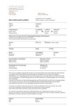
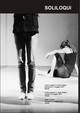
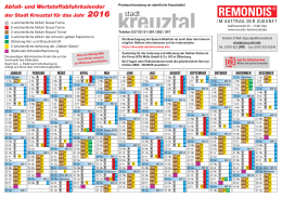
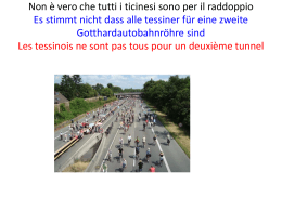
FIAMMA GAS E FORNI DORIGO
Ufficio: Piazza L. Da Vinci, 5 - CAORLE - Venezia
Magazzino spedizione: CASALE SUL SILE - Tv
www.fornidorigo.it - www.fiammagas.it - www.universepizza.it
+39 0421 210432
+39 348 7693538
+39 0421 210725
IT
LIBRETTO DI INSTALLAZIONE
GB
INSTALLATION GUIDE
DE
LIBRETTO DI INSTALLAZIONE
FR
LIBRETTO DI INSTALLAZIONE
IT
PREPARAZIONE SOLAIO
Predisporre un solaio portante alto da terra cm. 94. Con il materiale isolante di cm. 10 e il piano in
refrattario cotto di spessore cm. 6 si avrà un'altezza di lavoro complessiva di cm.110 da terra, un'
altezza ottimale per un operatore alto 160/165 cm.
Per ottenere un'altezza maggiore o minore, variare la distanza dal suolo del solaio portante
La superficie minima del piano d'appoggio per i nostri forni sono espresse in centimetri e sono utili
per ingombro forno ed isolamento superiore. E' da aggiungere lo spessore del muretto di finitura
esterna. Considerare eventuale pedana e marmo.
GB
SUPPORT FLOOR
Prearrange the load bearing floor (load quintal 20) high cm. 94 from the ground. Make a levelled
casting with fine cement to fill totally the tank
Minimum surface for the support floor useful for the overall dimensions of the oven on the table.
The support floor completed in that way will have a height of cm. 104; by installing the insulated
material and the floor made of refractory cotto it will result a height from the ground of cm. 110,
(optimum level for an operator tall 160/165 cm.). To reach a height in + or change that one of the
support floor.
Consider in addition the thickness of the outside finishing wall, eventual granite shelf for depth
and/or footboard for height.
DE
AUSTELLUNGSPLAN
Den Tragboden ( Tragkraft 1600 kg ) 94 cm. Vom Boden vorbereiten.
Die Wanne mit einem gut liveliertem Glattstrich aus feinem Zement komplett auffüllen.
Die minimale Grudflaeche des Unterbaus sollte um die Wandstareke der Aussenzand
vergroessert werden ( cm. Nützlich um den Ofen einzupassen und um die Isolieruleistung zu
erhalten). Die Stellflache wird letztendlich eine Höhe von 114 cm haben, auf denen die Schicht
gebrannter Schamottsteine ( Dicke 6 cm. ) aufgetragen wird, sodass man eine Arbeitshöhe von
110 cm. vom Erdboden erreicht (das ist die optimale Arbeitshöhe in + oder zu ändern, sollte die
Unterbauhöhe geändert werden. Considerare eventuale pedana e marmo.
FR
PREPARAZIONE SOLAIO
Disposer tout d'abord la dalle portante (change 14 x) à une hauteur de 94 cm du sol.
Faire une coulée, bien nivelée, en ciment jusqu'à remplissage total du réceptacle.
Superficie minimum du plan d'appui (surface utile pour le four et l'isolation supérieure). Par
conséquent, considérer en plus l'épaisseur du muret de finition externe.
Le plan d'appui ainsi terminé aura hauteur de 105 cm. En posant le plan en briques réfractaires
(épaisseur cm.), on aura une hauteur de travail de 110 cm en partant du sol (hauteur optimale
pour un opérateur mesurant 160/165 cm ). Afin d'obtenir une hauteur différente, changer celle de
la dalle portante. Considerare eventuale pedana e marmo.
Fig. 1
MODELLO FORNI
DORIGO EXP
DORIGO A
DORIGO B
DORIGO C
Fig. 2
Mis. Interna
Ø 85
Ø 115
Ø 145
115 x 150
Mis. Esterna
130 x 140
160 x 180
190 x 200
160 x 200
Carico
16 q.li
18 q.li
20 q.li
20 qli
Isolanti
Nr 10
Nr 20
Nr 26
Nr 26
Peso
9 q.li
14 q.li
16 q.li
16 q.li
IT
GB
BASE DI SOSTEGNO METALLICA
Avvitare le viti del telaio senza fissarle; considerare la parte anteriore aperta, le parti laterali e la
parte posteriore come dalla foto. Agganciare la vasca e fissare le viti.
METALLIC SUPPORT AND BASE
Screw as shown but not completely, consider the advance part of oven support is open, fit the
base on support as shown and screw completely.
DE
METALLISCHE STÜTZFLÄCHE
Schrauben an Gerüst auflegen ohne anzuziehen; Vorderseite offen lassen, Seite und Hinterseite
siehe Fotos. Wanne anlegen und Schrauben befestigen. Die Schrauben des Rahmens anziehen;
die Vorderseite offenlassen die Seitenflächen
FR
BASE SOUTIEN MÉTALLIQUE
Vissé les vis du châssis sans les fixées; considéré la partie antérieur ouverte, les parties latérales
et la partie postérieur comme sur la photo. Lier le récipient métallique et fixer les vis.
Fig. 4
Fig. 3
MODELLO FORNI
DORIGO EXP
DORIGO A
DORIGO B
DORIGO C
IT
GB
Mis. Interna
Ø 85
Ø 115
Ø 145
115 x 150
Mis. Esterna Carico Isolanti 1 Isolanti 2
114 x 122
12 q.li
Nr 2
Nr 10
150 x 160
18 q.li
Nr 4
Nr 18
180 x 190
20 q.li
Nr 5
Nr 22
150 x 200
20 qli
Nr 5
Nr 22
ACCESSORI IN DOTAZIONE
Cemento plastico refrattario per livellare il piano; malta a
presa rapida; fibra ceramica; materiale isolante pressato per
supporto e porta di chiusura.
ACCESSORIES
Plastic cement, Pressed Ceramic fibre, Insulated material,
Door, Smoke flue, Insulation of upper part in ceramic fibre,
refractory mortar.
DE
BASE DI SOSTEGNO METALLICA
FR
ACCESSOIRE FOURNIS
Ciment plastique réfractaire pour niveler le plan ; mortier a
prise rapide ; fibre céramique ; matériel isolant presse pour
support ; parte de fermeture
Fig. 5
Peso
8 q.li
12 q.li
14 q.li
14 q.li
IT
MONTAGGIO ISOLAMENTO INFERIORE
Per la posa in opera su base in muratura, appoggiare ciascun componente dell'isolamento
inferiore di cm. 10 usando il cemento in dotazione, molto diluito, operando in modo di ottenere un
corpo unico tra il solaio senza lasciare vuoti in modo che il piano abbia un appoggio stabile ed
uniforme su tutta la superficie inferiore. Posizionare i componenti bene allineati e a contatto fra
loro. In ogni caso, a lavoro ultimato, la superficie superiore dei componenti dovrà essere
perfettamente planare e senza scalini.
Per la posa in opera su base metallica ritagliare e appoggiare la fibra ceramica in lastra rigida di
cm. 3 e successivamente ritagliare e appoggiare tutti i componenti dell'isolamento di cm. 10
senza spazi vuoti.
GB
ASSEMBLY LOWER INSULATION
Wall Support: Put the insulated material of height 10 cm side by side and obtain a planar lever of
support right to put the cooking plate
Metallic Support: Cover the base with rigid insulation material of 2, 5 cm and place tightly the
insulation material of 10 cm previously they should be shaped
DE
MONTAGE DER INNENISOLIERUNG
Bei gemauerter Basis: jedes Teil der unteren Isolierung von ca 10 cm so auflegen, dass es ein
einziges Stuck mit dem Sockel bildet, keine fugen vorhanden sind und die Flache eine stabile und
gleichmassige. Auflage auf der gesamten unteren Oberflache hat.
Bei metallischer Basis: Keramikfiber von 25 mm auflegen, danach da Isoliermaterial von ca 10
cm. Nach getaner Arbeit soll die Oberflache der einzelnen Teile glatt und ohne Stufen sein.
FR
MONTAGE DES BRIQUES ISOLANTES
Pour la mise en place sur base en maçonnerie appuyé claque composant de l'isolement inférieur
de 10 cm usant ciment normal très dilué, agissant pour obtenir un corps inique entre le châssis
sans laisser vide en fonction que le plan ai un appui stable et uniforme sur toute la superficie
inférieur. Positionner le composants bien alignés et à contact entre eux. Dans tous les cas, à
travail terminé, la superficie supérieure des composants devra être parfaitement plane et sans
échelons.
L
F
E
D
C
B
A
Fig. 6
BOCCA DEL FORNO
EXP
A
B
C
Larghezza esterna
68
80
80
80
Larghezza interna davanzale
45
57
57
57
Altezza esterna
40
45
45
45
Altezza interna
23
28
28
28
Altezze di accoppiamento
25
32
30
32
IT
GB
DE
FR
SCHEMA DI MONTAGGIO DEL PIANO DI COTTURA
I 4 componenti del piano refrattario sono perfettamente planari e non devono essere stuccati fra
di loro. Utilizzare il cemento plastico del secchio bianco esclusivamente per correggere le
imperfezioni del piano di appoggio ed ottenere così un perfetto livellamento del suolo.
Posizionare il davanzale “I“ per le misure di riferimento e mantenere una distanza tra il davanzale
e la parte anteriore sporgente dell'isolamento inferiore se si vuole appoggiare davanti un piano di
marmo.
Nel caso del sostegno metallico, posizionare il davanzale “I“ in linea con la parte anteriore
Posizionare gli elementi del piano refrattario rispettando la sequenza visualizzata in figura 10
utilizzando il 50% del cemento plastico in uso per ogni pezzo del piano di cottura.
ASSEMBLY COOKING PLATE
Locate the element "I" for verifying the real dimension and place the cooking surface. The 4
components of the refractory floor are perfectly planar, squared and shaped and they must not be
puttied one another. Use a vary soft coat of refractory mortar exclusively in order to correct the
support floor's slight faults, and obtaining a perfect levelling of the floor.
MONTAGE BACKOFEN
Die Elemente der Ebene aus gebranntem Plastikzement in der Reihefolge positionieren
Die Komponenten der Ebene aus gebranntem Schamottstein sind absolut plan, rechtwindlig und
formgenau und müssen NICHT miteinander durch Mörtel verbunden werden.
Um die Ebenheit der Auglagefläche zu korrigieren, verwendet man eine sehr dünne Schicht aus
Schamottmörtel und damit sicher zu stellen, dass der Unterbau genauestens in Wasser steht
Legen Sie die einzelnen Teile des Backofen auf wie auf dem Foto, verwenden Sie dabei 50% des
plastischen Zements.
MONTAGE PLAN DE CUISSON
Positionner les 4 éléments en briques réfractaires en utilisant une fine couche de mastic
réfractaire de façon à obtenir une parfaite mise à niveau des pièces.
Utilisé le ciment plastique pour corriger les imperfections du plan d'appui obtenant un niveau
parfait . Positionner le record “I“ pour les mesures de références. Positionner les éléments du
plan réfractaire respectant la séquence en figure utilisant le 50% de ciment plastique.
G
E L F
F L E
E
L
F
3
G
2
4
1
H
I
Fig. 7
ESEMPIO DI PREDISPOSIZIONE FORO PER FIAMMA GAS
DORIGO 115
DORIGO 145
Bocca del forno
I
70 x 10
80 x 10
80 x 10
80 x 10
Davanzale
H
24
36
30
36
Diametro forno
G
85
115
145
115 x 150
Spessore cupola
F
6
6
6
6
Isolamento superiore
L
10
10
10
10
Rifinitura
M
5
5
5
5
Altezza solaio
A
94
94
94
94
Altezza piano cottura
D
6
6
6
6
Altezza interna forno
E
41
41
44
41
Isolamento inferiore 1
B
2,5
2,5
2,5
2,5
Isolamento inferiore 2
C
10
10
10
10
PROFONDITA’ TOTALE
LARGHEZZA TOTALE
ALTEZZA TOTALE
130
172
196
207
130
157
187
157
< 190
< 190
< 190
< 190
H
D
Fig. 8
C
B
IT
GB
DE
FR
SCHEMI MONTAGGIO CUPOLA DORIGO EXP 85
Posizionare a secco gli elementi di volta nel seguente ordine:
A. Accostare i laterali 1 e 2; B. Accostare i rimanenti laterali 3 e 4; C. Sovrapporre l'elemento
circolare 5, dopo avere verificato la perfetta messa in opera degli altri spicchi; D. Attaccare con
il cemento plastico la Bocca 6 e il davanzale "I".
Le fessure dovranno essere stuccati solo esternamente con il resto del cemento plastico.
Fissare successivamente il raccordo fumi con tasselli e cemento plastico.
ASSEMBLY COUPLE DORIGO EXP 85
Position, dry, the crown's elements in the following order:
A. Approach the laterals 1 and 2; B. Approach the remaining laterals 3 and 4. C. At least
overlap the precope 5 after checking the perfect installation of the other panels. D. Fix the
element 6 with plastic cement and position element “ I ”
The crown's components, shall be puttied only outside with refractory mortal, without let it enter
between the joints, stopping the expansion of the single panels. For this reason, fill preliminarily
the external joints with ceramic fibres and/or put along these joints some stripes of very thin wire
gauze. Fix the flue connection with dowel and mortar.
MONTAGGIO CUPOLA DORIGO EXP 85
Die Ebene mit der Oeffunug Positionieren wie sie im Bild dargestellt sind
Die Elemente OHNE BINDUGSMITTEL in folgender Reihenfolge aufstellen:
A. Die Seitenteile 1 und 2 aufstellen;
B. Die übrigen Seitenteile 3 und 4 anstellen
C. Zum Schluss das umlaufende Element 5 Aufsetzen, nachdem man den perfekten Sitz der
anderen Teile uberpruft hat. D. Attaccare con il cemento plastico la Bocca 6 e il davanzale "I".
Die Komponente des Ofengewölbes müssen nur aussentsitig verputzt werden, dazu verwenden
man ZementPlastik, ohne dass der Mörtel in di Zwischienfuegen dringt, um somit das Ausdehnen
der einzelen Teile zu ermöglichen. Als Vorbeugemaßnahme füllt man die Zwischen fügen vor dem
Verputzen mit KERAMIKFASER.
E. Fissare successivamente il raccordo fumi con tasselli e cemento plastico.
INSTRUCTION DE MONTAGE DU FOUR DORIGO EXP 85
Poser À sec les éléments de voûte. ( Ne pas cimenter les jointures ).
A. Poser À sec les
éléments de voûte 1-2;
B. Poser À sec les éléments de voûte 3 y 4; Assemblé les calottes
l'une avec l'autre, C. Poser le element 5 y vérifié les fissures et attaché avec le ciment l'arc
d'entré et le record.
D. Attaché avec le ciment plastique l’arc d’entré 6 e il davanzale "I".
Ne mastiquer les éléments de la voûte qu'à l'extérieur du mastic réfractaire sans qu'il n'entre
dans les jointures car cela empêcherait la dilatation de chaque élément
E. Fissare successivamente le record con tasselli e cemento plastico.
6
1
4
5
3
Fig. 9
2
10
10
IT
SCHEMI MONTAGGIO CUPOLA DORIGO A 115
Posizionare a secco gli elementi di volta nel seguente ordine:
A. Accostare l'elemento 1;
B. Accostare i laterali 2, 3, 4, 5 e 6 uno all'altro;
C. Accostare
l'elemento di chiusura 7;
D. Sovrapporre gli elementi 8 e 9, dopo avere verificato la
perfetta messa in opera degli altri spicchi;
E. Attaccare con il cemento plastico la Bocca
10 e il davanzale "I".
Le fessure dovranno essere stuccati solo esternamente con il resto del cemento plastico.
Fissare successivamente il raccordo fumi con tasselli e cemento plastico
GB
ASSEMBLY COUPLE DORIGO A 115
Position, dry, the crown's elements in the following order:
A. Approach the element 1 ;
B. Approach the laterals 2, 3, 4, 5 and 6 side by side;
C. Approach the last lateral 7;
D. At least overlap the precope 8 and 9 after checking the
perfect installation of the other panels.
E. Fix the element 10 with plastic cement and
position element “ I ”
The crown's components, shall be puttied only outside with refractory mortal, without let it enter
between the joints, stopping the expansion of the single panels. For this reason, fill preliminarily
the external joints with ceramic fibres and/or put along these joints some stripes of very thin wire
gauze. Fix the flue connection with dowel and mortar.
DE
FR
MONTAGGIO CUPOLA DORIGO A 115
Die Ebene mit der Oeffunug Positionieren wie sie im Bild dargestellt sind
Die Elemente OHNE BINDUGSMITTEL in folgender Reihenfolge aufstellen:
A. Die Seitenteile 1 anstellen;
B. Die Seitenteile 2, 3, 4, 5, und 6 aufstellen;
C. Die
übrigen Seitenteile 7 anstellen;
D. Zum Schluss das umlaufende Element 8 und 9
Aufsetzen, nachdem man den perfekten Sitz der anderen Teile uberpruft hat; E. Attaccare con il
cemento plastico la Bocca 6 e il davanzale "I".
Die Komponente des Ofengewölbes müssen nur aussentsitig verputzt werden, dazu verwenden
man ZementPlastik, ohne dass der Mörtel in di Zwischienfuegen dringt, um somit das Ausdehnen
der einzelen Teile zu ermöglichen. Als Vorbeugemaßnahme füllt man die Zwischen fügen vor dem
Verputzen mit KERAMIKFASER.
INSTRUCTION DE MONTAGE DU FOUR DORIGO A 115
A. Poser la parte anterieur 1 ;
B. Poser À sec les éléments de voûte l'une avec l'autre ne pas
cimenter les jointures les éléments 2, 3, 4, 5 y 6;
C. Poser À sec les éléments de voûte 7;
C. Poser le element 8 y 9 vérifié les fissures;
D. Attaché avec le ciment plastique l’arc
d’entré 6 e il davanzale "I". Ne mastiquer les éléments de la voûte qu'à l'extérieur du mastic
réfractaire sans qu'il n'entre dans les jointures car cela empêcherait la dilatation de chaque
élément. E. Fissare successivamente le record con tasselli e cemento plastico.
6
5
8
4
3
1
2
Fig. 12
7
9
10
10
17
17
10
IT
SCHEMI MONTAGGIO CUPOLA DORIGO B 145
Posizionare a secco gli elementi di volta nel seguente ordine:
A. Accostare l'elemento 1;
B. Accostare i laterali 2, 3, 4, 5 e 6 uno all'altro;
C. Accostare
l'elemento di chiusura 7;
D. Sovrapporre gli elementi 8 e 9, dopo avere verificato la
perfetta messa in opera degli altri spicchi;
E. Attaccare con il cemento plastico la Bocca
10 e il davanzale "I".
Le fessure dovranno essere stuccati solo esternamente con il resto del cemento plastico.
Fissare successivamente il raccordo fumi con tasselli e cemento plastico
GB
ASSEMBLY COUPLE DORIGO B 145
Position, dry, the crown's elements in the following order:
A. Approach the element 1 ;
B. Approach the laterals 2, 3, 4, 5 and 6 side by side;
C. Approach the last lateral 7;
D. At least overlap the precope 8 and 9 after checking the
perfect installation of the other panels.
E. Fix the element 10 with plastic cement and
position element “ I ”
The crown's components, shall be puttied only outside with refractory mortal, without let it enter
between the joints, stopping the expansion of the single panels. For this reason, fill preliminarily
the external joints with ceramic fibres and/or put along these joints some stripes of very thin wire
gauze. Fix the flue connection with dowel and mortar.
DE
FR
MONTAGGIO CUPOLA DORIGO B 145
Die Ebene mit der Oeffunug Positionieren wie sie im Bild dargestellt sind
Die Elemente OHNE BINDUGSMITTEL in folgender Reihenfolge aufstellen:
A. Die Seitenteile 1 anstellen;
B. Die Seitenteile 2, 3, 4, 5, und 6 aufstellen;
C. Die
übrigen Seitenteile 7 anstellen;
D. Zum Schluss das umlaufende Element 8 und 9
Aufsetzen, nachdem man den perfekten Sitz der anderen Teile uberpruft hat; E. Attaccare con il
cemento plastico la Bocca 6 e il davanzale "I".
Die Komponente des Ofengewölbes müssen nur aussentsitig verputzt werden, dazu verwenden
man ZementPlastik, ohne dass der Mörtel in di Zwischienfuegen dringt, um somit das Ausdehnen
der einzelen Teile zu ermöglichen. Als Vorbeugemaßnahme füllt man die Zwischen fügen vor dem
Verputzen mit KERAMIKFASER.
INSTRUCTION DE MONTAGE DU FOUR DORIGO B 145
A. Poser la parte anterieur 1 ;
B. Poser À sec les éléments de voûte l'une avec l'autre ne pas
cimenter les jointures les éléments 2, 3, 4, 5 y 6;
C. Poser À sec les éléments de voûte 7;
C. Poser le element 8 y 9 vérifié les fissures;
D. Attaché avec le ciment plastique l’arc
d’entré 6 e il davanzale "I". Ne mastiquer les éléments de la voûte qu'à l'extérieur du mastic
réfractaire sans qu'il n'entre dans les jointures car cela empêcherait la dilatation de chaque
élément. E. Fissare successivamente le record con tasselli e cemento plastico.
3
4
8
5
6
1
7
Fig. 12
2
9
10
10
17
17
10
IT
ISOLAMENTO SUPERIORE
Procedere con la costruzione del muretto di finitura esterna.
Con la base metallica, ricoprire a livello della vasca con mistura di cemento e argilla espansa.
Coprire interamente la cupola con la fibra ceramica in dotazione e successivamente con lana di
roccia. Prima di chiudere la struttura, riempire il tutto con argilla espansa fino ad una altezza di
cm. 15 c.a. sopra la sommità del forno. Non sigillare la struttura, ma lasciare sempre aperture di
traspirazione.
GB
UPPER INSULATION
The professional DORIGO oven, thanks to the special materials employed, permit an outstanding
heat's storage. This heat must not be able to leak outside, therefore it's necessary a good thermal
insulation. Cover totally the dome with a thickness of about 4- 8 cm of ceramic fibre and stone….
Go on with the building of the outside finishing wall. Before closing the structure, fill with …, to
reach an height of 20 cm. Don't seal the structure, but leave always openings of transpiration
Cover totally the dome with a thickness of about 4- 8 cm of ceramic fibre and stone…. Go on with
the building of the outside finishing wall. Before closing the structure, fill with …, to reach an
height of 20 cm. Don't seal the structure, but leave always openings of transpiration
DE
AUSSEIENISOLIERUNG
Der Ofen erlaubt dank seiner eingesetzten Spezialmaterialen einen hervorragenden Wärmestau (
Waermespecherung ) Diese Wärme darf nicht nach außen verloren gehen, deshalb ist eine gute
thermische Isolierung notwendig.
Das Ofengewölbe vollständig mit KeramikFiber oder Steinwolle in einen Dicken von ca. 8 cm
bedecken. Danach die Konstruktion des Außenmauerchens beenden. Bevor man das Gebilde
schließe füllt man das Ganze mit Laterlite über auf. Die Struktur nicht vollständig verschlisessen
sondern immer Öffnungen zur Luftzirkulation lassen.
FR
ISOLATION SUPÉRIEURE
Le four a bois grâce aux matériaux spéciaux employés perme une accumulation de chaleur
exceptionnelle Cette chaleur e doit cependant pas se disperser vers l'extérieur une bonne
isolation thermique est donc indispensable
Recouvrir complètement la voûte avec de la laine de verre sur une épaisseur d'environ 8 cm.
Poursuivre avec la construction du mur de finition extérieur. Avant de refermer la structure, remplir
le tout avec de l'argile expansée jusqu'à une hauteur d'environ au dessus de la surface du four
Ne pas sceller la structure amis laisser toujours des ouvertures pour la transpiration
IT
PULIZIA INTERNA E MANUTENZIONE
Per la pulizia interna del forno si consiglia di utilizzare gli apposti spazzoloni in ottone.
Non utilizzare mai stracci bagnati
Non gettare mai acqua all'interno: è importante evitare forti sbalzi termici che possono
danneggiare il forno
GB
INSIDE CLEANING AND MAINTENANCE
For the inside cleaning of the oven, we suggest to use the suitable brass brushes.
Do not use wet rags
Never throw water inside, it is important to avoid strong thermal rushes which could damage the
handwork
DE
FR
INNETEININGUNG UND PFLEGE
Für die Innenteiningung des Ofens empfiehlt es sich geeignete Buersein aus Messing zu
verwenden
Es wird jedoch darauf hingewiesen, vor Gebrauch, da ueberschuessige Wasser abzuschütteln
Keine nassen Lappen benutzen
Niemals Wasser in das Innere gießen; Es ist wichtig starke Temperaturschwankungen zu
vermeiden, da dadurch der Ofen beschädigt werden könnte.
NETTOYAGE EXTÉRIEUR ET MANUTENTION
Pour le nettoyage intérieur du four, il est conseille d'utiliser les brosses spéciales en laiton
Ne pas utiliser de chiffons mouilles
Ne jamais jeter d'eau a l'intérieur il est important d'éviter les forts écarts de températures qui
pourraient abîmer le produit
IT
ACCENSIONE DEL FORNO
Il forno contiene un quantitativo d'acqua che in fase di asciugamento non deve trasformarsi in
vapore all'interno del forno. E' indispensabile pertanto al fine di evitare tale effetto che potrebbe
creare delle lesioni procedere con la massima attenzione con la prima accensione. La prima
accensione deve avvenire in modo graduale e costante per la durata di una settimana e si
consiglia di procedere come segue: 1. accendere il fuoco nella parte centrale del forno; 2.
mantenere la temperatura interna a circa 150° C per i primi 2 giorni; 3. aumentare di 50° C al
giorno fino alla completa deumidificazione del forno. In caso di prolungata inattività del forno
procedere ad una lenta riaccensione per la durata di almeno 12 ore.
Eventuali incrinature all'interno dei componenti della volta sono perfettamente normali e dovute
GB
OVEN'S FIRING
The oven, when it's new, has big water's content, which during the drying must not turn into steam
inside the handwork.
Therefore it's necessary to start very carefully with the first firing in order to avoid the above
mentioned effect, which could create cracks to the handwork.
For the first firing, which has to be carried out gradually and constantly for 7 days, we suggest
following these instructions:
Light the fire in the central part of the oven.
Keep the inside temperature to 150 C = 302 F for the first two days (24 hours for each day 1 and
2 day).
Rise of 50 C = 102 F a day until the total dehumidification of the handwork.
In case of an extended inactivity of the oven, proceed with a slow relighting for about 12 hours;
little crakes inside the vault's components are perfectly normal and are due to the expansion of
these ones (thermal expansion joints).
DE
INBETRIEBNAHME DES OFENS
Der neue Ofen beinhaltet Wasser, das sich in der Trocknungsphase nicht im Inneren des Ofens
zu Dampf umwandeln darf.
Um diesem Effekt zu verhindern der zur Beschaedingung des Ofens fueheren könnte ist es
notewendig bei der Inbetriebnahme aeussester Vorsicht vorzugehen
Bei der ersten Inbetriebnahme, die in einen Fortgehenden und konstanten Prozess, der sich über
einen Zeitraum einer Woche erstreckt, rät es sich wie folgt vorzugehen:
Das Feure im Mittelpunkt des Ofens anzünden
Die innere Temperatur für 2 Tage bei ca. 150 C. halten
Die Temperatur um 50 pro Tag erhöhen, bis die vollständige Austrocknung des Ofens erreicht ist.
Im falle eines längeren Stillstand des Ofens ist eine langsame Wiederinbetriebnahme von
mindestens 12 Sunden notwendig. Eventuell auftretende leichte Risse im Innenbereich des Ofens
sind bedingt durch die Ausdehnung der Komponenten vollkommen normale Erscheinisse.
FR
ALLUMAGE DU FOUR :
Le four lorsqu est neuf contient une importante quantité d'eau qui au moment du séchage ne doit
pas se transformer en vapeur a l'intérieur de l'ouvrage
Il est donc indispensable afin d'éviter un tel effet qui pourrait créer des dommages au produit faire
très attention au premier allumage
Pour le premier allumage, qui doit se faire de façon graduelle et constante sur une durée de 3-4
jours, il est conseille de procéder ainsi :
Allumer le feu dans la partie centrale du four
Maintenir la température interne à environ 150° le premier jour
Augmenter de 50 degrés par jour jusqu'à complète déshumidification de l'ensemble
En cas d'inactivité prolongée du four procéder a un lent reallumage sur une durée d'au moins 6
heures. De legeres fêlures pourraient éventuellement apparaître a l'intérieur des composants de
la voûte elles sont parfaitement normales et sont dues a leur propre dilation ( joints de dilatation
thermique
10
10
18
18
Scarica