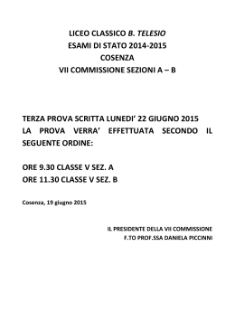
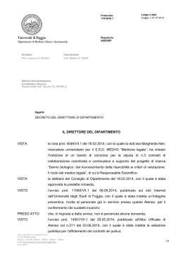
D Montage - und Betriebsanleitung Kupplungskugel mit Halterung (KmH) Westfalia-Bestell-Nr.: 313 121 Seite 2-5 GB Installation and Operating Instructions Coupling Ball with Bracket (CBB) Westfalia Order No.: 313 121 page 6-9 F NL I E Instructions de montage et demploi Boule dattelage avec support Référence Westfalia:313 121 page 10-13 Montagehandleiding en gebruiksaanwijzing trekhaak Westfalia-bestelnr.: 313 121 zijde 14-17 Istruzioni di montaggio e d'uso per la sfera del gancio di traino con supporto codice Westfalia: 313 121 page 18-28 Instrucciones de servicio y montaje del enganche esférico con fijación Núm. de pedido Westfalia: 313 121 page 29-32 313 121 691 101 - 24/02 V Mercedes Benz 1 D Montage - und Betriebsanleitung Kupplungskugel mit Halterung Westfalia-Bestell-Nr. : Typ: EG-Genehmigungszeichen: 313 121 600 001 313 116 e13 00-0106 Verwendungsbereich: Mercedes Benz, S 210 ab 5/96 (E-Klasse Kombi) Amtliche Typenbezeichnung nach EG-Typgenehmigung: 210 K Achtung: Bei Motorisierung 300er Turbodiesel (Motor 606) in Verbindung mit Klimaanlage bzw. -automatik muß für den Anhängerbetrieb ein Getriebeölkühler mit Gebläsemotor, sowie ein Gebläse für den Motorölkühler nachgerüstet werden. Ist zusätzlich eine Standheizung vorhanden, muß diese demontiert werden, da sie den Bauraum der oben genannten Bauteile belegt. Technische Daten : Der geprüfte D - Wert beträgt 11,5 kN. Dieser entspricht zum Beispiel einer Anhängelast von 2200 kg und einem zulässigen Gesamtgewicht von 2500 kg. Die geprüfte Stützlast beträgt 84 kg. Für den Fahrbetrieb sind die Angaben des Fahrzeugherstellers bzgl. Anhängelast und Stützlast maßgebend, wobei die geprüften Werte der Anhängevorrichtung nicht überschritten werden dürfen. Hinweise : Die Anhängevorrichtung ist ein Sicherheitsteil und darf nur von Fachpersonal montiert werden. Sofern Ersatzteile erforderlich werden, dürfen auch diese nur von Fachpersonal am unbeschädigten Originalteil verbaut werden. Jegliche Änderungen bzw. Umbauten an der Anhängevorrichtung sind unzulässig. Sie führen überdies zum Erlöschen der Betriebserlaubnis. Bei Fahrt mit Anhänger sind die Fahrthinweise in der Betriebsanleitung des Fahrzeugherstellers zu beachten. Die Anhänger müssen mit einer entsprechenden Zugkugelkupplung ausgerüstet sein. Muß durch den Anbau der Anhängevorrichtung die Abschleppöse entfernt werden, dient diese als Ersatz hierfür, sofern die zulässige Anhängelast nicht überschritten wird und der Abschleppvorgang auf verkehrsüblichen Straßen erfolgt. D Die Kugel bzw. Kupplung ist sauber zu halten und zu fetten. Achtung : Bei Benutzung von Spurstabilisierungseinrichtungen, wie z.B. der Westfalia "SSK" muß die Kupplungskugel fettfrei sein. Die Hinweise in der Bedienungsanleitung beachten! Der Durchmesser der Kugel ist von Zeit zu Zeit zu überprüfen. Sobald an einer beliebigen Stelle eine Verschleißgrenze von 49,0 mm erreicht ist, darf die Anhängevorrichtung aus Sicherheitsgründen nicht mehr benutzt werden. Die vom Fahrzeughersteller serienmäßig genehmigten Befestigungspunkte sind eingehalten. Nationale Richtlinien über die Anbauabnahmen sind zu beachten. Diese Montage- und Betriebsanleitung ist den Kfz. - Papieren beizufügen. Allgemeine Montagehinweise : Isoliermasse bzw. Unterbodenschutz am Kfz. - falls vorhanden - im Bereich der Anlagefläche der Anhängevorrichtung entfernen. Blanke Karosseriestellen mit Rostschutzfarbe streichen. Elektrische Anlage 7 - polig gemäß DINV 72570 montieren. Elektrische Anlage 13 - polig gemäß ISO 11446 montieren. Diese Anhängevorrichtung einschließlich aller Montageteile wiegt 17,5 kg. Bitte berücksichtigen Sie, daß sich das Leergewicht Ihres Kfz. nach Montage der Anhängevorrichtung um diesen Betrag erhöht. Lieferbare Ersatzteilumfänge der Kupplungskugel mit Halterung Ersatzteil-Nr. Bezeichnung 913 121 650 001 Befestigungsteile, Pos. 4 - 8 913 121 611 001 Versteifung, Pos. 2 und 3 D Umfang der Kupplungskugel mit Halterung Pos. 1 2 3 4 5 6 7 8 Bezeichnung KmH - Grundteil Versteifung links Versteifung rechts Gegenlasche Scheibe 10,5 x 25 x 4 Mutter M 10, Festigkeitsklasse 8 Schraube M 12 x 1,5 x 70, Festigkeitsklasse 10.9 Anbauanweisung Anzahl 1 1 1 2 4 4 4 1 Montageanleitung : 1.) Hinteren Stoßfänger demontieren. 2.) Im Laderaum die Verkleidungen Heckmittelstück und Seitenteile rechts und links demontieren. 3.) Reserverad ausbauen. 4.) Unter dem Fahrzeug im Bereich der Anlageflächen der Querträgerenden " c " den Unterbodenschutz entfernen. 5.) Die durch Körnerschläge gekennzeichneten Bohrpunkte mit ø 13mm vorbohren und auf ø 18mm ausarbeiten. 6.) Die Versteifungen " 2 " und " 3 " vom Laderaum her in die Längsträger des Fahrzeuges einsetzen. Hinweis: Die Versteifungen sind mit R bzw. L für die rechte bzw. linke Seite gekenzeichnet 7.) Die Gegenlaschen " 4 " bei den Befestigungspunkten " b " einsetzen und mit Scheiben 10,5 x 25 x 4 und Muttern M 10 von Hand vormontieren. 8.) Versteifungen so ausrichten, daß die Schraubpunkte " a " mit den im Fahrzeug erstellten Bohrungen zur Deckung kommen. 9.) Das KmH-Grundteil " 1 " mit den Schrauben M 12 x 1,5 x 70 an den Befestigungspunkten " a " vormontieren. 10.) Die KmH ausrichten. 11.) Alle Muttern bzw. Schrauben mit dem vorgegebenem Drehmoment anziehen. Anzugsdrehmoment für M10 = 40 Nm Anzugsdrehmoment für M12 = 95 Nm 12.) Alle demontierten Teile ordnungsgemäß einbauen. Änderungen vorbehalten. 4 5 M10 6 10.5x25x4 5 "C" 6 5 L "b" 2 "b" 4 7 7 "a" "a" M12x1.5x70 4 "b" 1 "b" 5 3 6 5 "a" "a" 6 65 7 313 121 691 101 minimale afstand t.o.v. voertuigonderdelen Mindestabstand von Kfz.-Teilen 7 Der Freiraum nach Anhang VII, Abbildung 30 der Richtlinie 94/20/EG ist zu gewährleisten. Frirummet skal overholdes iht. bilag VII, fig. 30 i direktiv 94/20/EF. Volný prostor ve smyslu Pøílohy VII, obr. 30 Smìrnice è. 94/20/EG musí být zaruèen. Debe garantizarse el espacio libre, conforme al anexo VII, figura 30 de la directiva comunitaria CE/94/20. La zone de dégagement doit être garantie conformément à l'annexe VII, illustration 30 de la directive 94/ 20/CE. FIN Vapaa tila on taattava direktiivin 94/20/EY liitteen VII, kuvan 30 mukaisesti. GB The clearance specified in appendix VII, diagram 30 of guideline 94/20/EG must be guaranteed. GR ÐñÝðåé íá åîáóöáëßæåôáé ï åëåýèåñïò ÷þñïò óýìöùíá ìå ôï ðáñÜñôçìá VII, åéêüíá 30 ôçò Ïäçãßáò 94/ 20/EÏÊ. HBiztosítani kell a 94/20/EK irányelv szerinti, VII. számú függelék 30. ábrában jelölt szabad teret. IDeve essere garantito lo spazio libero secondo l'allegato VII, figura 30 della direttiva 94/20/CE. NFrirommet etter tillegg VII, avbilding 30 i direktiv 94/20/EEC skal overholdes. NL De tussenruimte conform supplement VII, afbeelding 30 van de richtlijn 94/20/EG moet in acht worden genomen. PGarantir a zona livre, conforme Anexo VII, gráfico 30 da Norma 94/20/CE. PL Nale¿y zagwarantowaæ przestrzeñ swobodn¹ wed³ug za³¹cznika VII, ilustracja 30 wytycznej 94/20/EG . SSpelrummet enligt bilaga VII, figur 30 i riktlinje 94/20/EG skall garanteras. SLO - Zagotoviti zraènost po priklopu VII, slika 30, smernice 94/20/EG . SK Volný priestor v zmysle Prílohy VII, obr. 30 Smernice è. 94/20/EG musí by zaruèený. TR 94/20/EG Yönetmeliði, Ek VII, Resim 30'da belirtilen serbest alan býrakýlmalýdýr. DDK CZ EFFIN GB GR HINNL PPL SSLO SK TR - bei zulässigem Gesamtgewicht des Fahrzeuges ved tilladt samlet vægt for køretøjet pøi celkové pøípustné hmotnosti vozidla con peso total autorizado del vehículo pour poids total en charge autorisé du véhicule ajoneuvon suurimmalla sallitulla kokonaispainolla at laden weight of the vehicle ãéá ôï åðéôñåðôü ìéêôü âÜñïò ôïõ ï÷Þìáôïò a jármû megengedett össztömege esetén per un peso complessivo ammesso del veicolo ved kjøretøyets tillatte totalvekt bij toelaatbaar totaal gewicht van het voertuig com o peso total permitido do veículo przy dopuszczalnym ciê¿arze ca³kowitym pojazdu vid fordonets tillåtna totalvikt pri dovoljeni skupni tei vozila pri celkovej prípustnej hmotnosti vozidla Taþýtýn azami toplam aðýrlýðýnda DDK CZ EF- 6 GB Installation and Operating Instructions Coupling Ball with Bracket (CBB) Westfalia Order No.: Type: EC Auth. Des.: 313 121 600 001 313 116 e13 00-0106 Application: Mercedes-Benz S 210 as of June 1995; (E Class estate/station wagon) 210 K EC Authorised Designation: Attention: If the vehicle to which the towing device is to be fitted is a 300 Turbodiesel model (engine 606) equipped with air-conditioning or automatic air-conditioning system, a transmission oil cooler with fan motor and a fan for the engine oil cooler must both be retrofitted. If the vehicle is also equipped with a parking/auxiliary heater, this heater must be removed because it is located in the space where the components mentioned above have to be installed. Technical Data: The tested D-value is 11,5 kN. This corresponds, for example, to a towed weight of 2200 kg and a permissible total weight of 2500 kg. The tested trailer nose weight is 84 kg. For driving, the data of the vehicle manufacturer with regard to the towed weight and trailer nose weight are decisive, whereby the tested values of the CBB may not be exceeded. Notes: The CBB is a safety part and may only be mounted by specially trained personnel. Should spare parts be required, these may also only be mounted on the undamaged original-equipment part by specially trained personnel. No changes or modifications to the CBB are permitted. When driving with a trailer, observe the driving instructions in the vehicle manufacturer's operating instructions. The trailer must be equipped with an appropriate towing coupling ball. If installing the CBB necessitates the removal of the towing eye, the CBB serves as a replacement, provided the permissible towed weight is not exceeded and the towing takes place on normal roads. 7 GB The ball and coupling must be kept clean and greased. Important: When using track stabilising devices, e.g. the Westfalia "SSK", the coupling ball must be grease-free. Follow the instructions in the operating instructions. Check the ball diameter from time to time. As soon as a diameter of 49.0 mm is reached at any given point, the CBB may no longer be used for safety reasons. The fixing points specified as standard must be observed. National guidelines concerning official approval of auxiliaries must be observed. These installation and operating instructions must be enclosed with the vehicle papers. General Installation Instructions: If present, remove insulating compound and/or underseal in the area of the CBB contact surfaces. Coat bare bodywork with anti-corrosion paint. Mount 7-pin electrical system as per DINV 72570. Mount 13-pin electrical system as per ISO 11446. This CBB including all mounting parts weighs 17,5 kg. Please take into account that the curb weight of your vehicle is increased by this amount after mounting the CBB. Available Spare Parts for Coupling Ball with Bracket Spare Part No. Description 913 121 650 001 Mounting parts, items 4 - 8 913 121 611 001 Reinforcement, items 2, 3 8 GB Parts of Coupling Ball with Bracket Item 1 2 3 4 5 6 7 8 Description CBB basic component Reinforcement, left Reinforcement, right Fishplate Washer 10,5 x 25 x 4 Nut M 10, strength class 8 Bolt M 12 x 1,5 x 70, strength class 10.9 Mounting and operating instructions Qty. 1 1 1 2 4 4 4 1 Installation Instructions: 1.) Remove the rear bumper. 2.) Remove the trim from the centre section of the rear panel and the left and right side panels in the luggage compartment 3.) Remove the spare wheel. 4.) Underneath the vehicle, remove the underseal around the areas where the towbar will make contact with the ends of the rear cross member "c". 5.) Predrill the drilling points marked by a prick-punch to Ø 13 mm and then drill them out to Ø 18 mm. 6.) Insert reinforcements "2" and "3" into the frame side members from within the luggage compartment. Note: The reinforcements are marked R and L for the right- and left-hand side. 7.) Insert fishplates "4" at fixing points "b" and pretighten by hand with the 10.5 x 25 x 4 washers and M 10 nuts. 8.) Align the reinforcements in such a way that the bolting points "a" align with the holes drilled in the vehicle. 9.) Bolt CBB basic component "1" loosely at fixing points "a" using the M 12 x 1.5 x 70 bolts. 10) Align the CBB 11.) Tighten all nuts and bolts to the specified torque: Tightening torque for M 10 = 40 Nm Tightening torque for M 12 = 95 Nm 12.) Refit/replace all the parts removed. Subject to change. 9 10 M10 6 10.5x25x4 5 "C" 6 5 L "b" 2 "b" 4 7 7 "a" "a" M12x1.5x70 4 "b" 1 "b" 5 3 6 5 "a" "a" 6 65 7 313 121 691 101 Distance à respecter des minimale afstand t.o.v. pièces du véhicule voertuigonderdelen Minimum clearance from Mindestabstand vehicle parts von Kfz.-Teilen 7 Der Freiraum nach Anhang VII, Abbildung 30 der Richtlinie 94/20/EG ist zu gewährleisten. Frirummet skal overholdes iht. bilag VII, fig. 30 i direktiv 94/20/EF. Volný prostor ve smyslu Pøílohy VII, obr. 30 Smìrnice è. 94/20/EG musí být zaruèen. Debe garantizarse el espacio libre, conforme al anexo VII, figura 30 de la directiva comunitaria CE/94/20. La zone de dégagement doit être garantie conformément à l'annexe VII, illustration 30 de la directive 94/ 20/CE. FIN Vapaa tila on taattava direktiivin 94/20/EY liitteen VII, kuvan 30 mukaisesti. GB The clearance specified in appendix VII, diagram 30 of guideline 94/20/EG must be guaranteed. GR ÐñÝðåé íá åîáóöáëßæåôáé ï åëåýèåñïò ÷þñïò óýìöùíá ìå ôï ðáñÜñôçìá VII, åéêüíá 30 ôçò Ïäçãßáò 94/ 20/EÏÊ. HBiztosítani kell a 94/20/EK irányelv szerinti, VII. számú függelék 30. ábrában jelölt szabad teret. IDeve essere garantito lo spazio libero secondo l'allegato VII, figura 30 della direttiva 94/20/CE. NFrirommet etter tillegg VII, avbilding 30 i direktiv 94/20/EEC skal overholdes. NL De tussenruimte conform supplement VII, afbeelding 30 van de richtlijn 94/20/EG moet in acht worden genomen. PGarantir a zona livre, conforme Anexo VII, gráfico 30 da Norma 94/20/CE. PL Nale¿y zagwarantowaæ przestrzeñ swobodn¹ wed³ug za³¹cznika VII, ilustracja 30 wytycznej 94/20/EG . SSpelrummet enligt bilaga VII, figur 30 i riktlinje 94/20/EG skall garanteras. SLO - Zagotoviti zraènost po priklopu VII, slika 30, smernice 94/20/EG . SK Volný priestor v zmysle Prílohy VII, obr. 30 Smernice è. 94/20/EG musí by zaruèený. TR 94/20/EG Yönetmeliði, Ek VII, Resim 30'da belirtilen serbest alan býrakýlmalýdýr. DDK CZ EFFIN GB GR HINNL PPL SSLO SK TR - bei zulässigem Gesamtgewicht des Fahrzeuges ved tilladt samlet vægt for køretøjet pøi celkové pøípustné hmotnosti vozidla con peso total autorizado del vehículo pour poids total en charge autorisé du véhicule ajoneuvon suurimmalla sallitulla kokonaispainolla at laden weight of the vehicle ãéá ôï åðéôñåðôü ìéêôü âÜñïò ôïõ ï÷Þìáôïò a jármû megengedett össztömege esetén per un peso complessivo ammesso del veicolo ved kjøretøyets tillatte totalvekt bij toelaatbaar totaal gewicht van het voertuig com o peso total permitido do veículo przy dopuszczalnym ciê¿arze ca³kowitym pojazdu vid fordonets tillåtna totalvikt pri dovoljeni skupni tei vozila pri celkovej prípustnej hmotnosti vozidla Taþýtýn azami toplam aðýrlýðýnda DDK CZ EF- 11 F Instructions de montage et demploi Boule dattelage avec support Référence Westfalia: Type: Code dautorisation CE: 313 121 600 001 313 116 e13 00-0106 Domaine dutilisation: Mercedes-Benz, S 210 à partir de 5/96 (Classe E Break) Désignation du type officielle suivant l'autorisation du type CE: 210 K Attention! Sur les véhicules équipés du moteur 606, Turbodiesel 300, en liaison avec un climatiseur ou un climatiseur automatique, en remorquage, il faut monter en supplément ultérieurement un radiateur de lhuile de la boîte de vitesses avec un moteur à soufflerie et une soufflerie pour le radiateur de lhuile du moteur. Si, en outre, une appareil de chauffage stationnaire est monté, celui-ci doit être démonté étant donné quil occupe la place des composants indiqués ci-dessus. Caractéristiques techniques: La valeur D contrôlée est de 11,5 kN. Celle-ci correspond par exemple à une charge remorquée de 2200 kg et à un poids total admissible de 2500 kg. La charge dappui contrôlée est de 84 kg. Les indications du constructeur du véhicule concernant la charge remorquée et la charge dappui sont déterminantes pour la marche du véhicule; toutefois, il ne faut pas dépasser les valeurs contrôlées. Remarques: La boule dattelage est une pièce de sécurité qui doit seulement être montée par des spécialistes. Si des pièces de rechange sont nécessaires, celles-ci doivent aussi être montées seulement par des spécialistes sur la pièce dorigine non endommagée. Toutes modifications ou transformations sur la boule dattelage sont interdites. Si on circule avec une remorque, il faut respecter les informations concernant la marche figurant sur les instructions demploi du constructeur du véhicule. Les remorques doivent être équipées dun attelage à boule de traction correspondant. Si lanneau de remorquage doit être enlevé pour le montage de la boule dattelage avec support, cette boule dattelage sert alors de dispositif de remplacement dans la mesure où la charge de remorquage admissible nest pas dépassée et si le remorquage est effectué sur des routes pour circulation normale. 12 F La boule ou lattelage doivent être maintenus propres et il faut les graisser. Attention! Si on utilise des dispositifs de stabilisation de la voie, p.ex.: le dispositif SSK de Westfalia, la boule dattelage doit être exempte de graisse. Il faut respecter les indications des instructions demploi. De temps en temps, il faut contrôler le diamètre de la boule. Dès quà un endroit quelconque, on atteint le diamètre de 49 mm ou moins, pour des raisons de sécurité, il ne faut plus utiliser la boule dattelage et son support. Les points de fixation homologués en série par le constructeur sont respectés. Les dispositions nationales relatives aux contrôles de réception doivent être respectées. Cette notice de montage et dutilisation doit être jointe aux documents du véhicule. Indications générales de montage: Sil y en a, enlever le mastic isolant et/ou la couche de protection du dessous de caisse sur le véhicule, au voisinage de la surface dappui de la boule dattelage. Badigeonner dune couche antirouille les surfaces nues de la carrosserie en utilisant de la peinture antirouille. Monter linstallation électrique à 7 pôles suivant la norme DINV 72 570. Monter linstallation électrique à 13 pôles suivant la norme ISO 11446. Cette boule dattelage et le support, y compris toutes les pièces de montage, pèsent 17,5 kg. Veuillez donc tenir compte que la poids à vide de votre véhicule, après le montage de la boule dattelage et du support, augmente de cette valeur. Étendues de livraison des pièces de rechange disponibles de la boule dattelage avec le support 913 121 650 001 Pièces de fixation, rep. 4 - 8 913 121 611 001 Raidisseur, rep. 2, 3 13 F Étendue de livraison de la boule dattelage et du support Rep. 1 2 3 4 5 6 7 8 Désignation Pièce de base boule dattelage et support Raidisseur gauche Raidisseur droit Contre-éclisses Rondelles 10,5 x 25 x 4 Écrou hexagonal M 10, classe de résistance 8 Vis à tête hexagonale M 12 x 1,5 x 70, classe de résistance 10.9 Instructions de montage et d'emploi Qté 1 1 1 2 4 4 4 1 Instructions de montage: 1.) Démonter lamortisseur de chocs arrière. 2.) Dans la zone de chargement, démonter les revêtements du milieu du hayon et les côtés, à droite et à gauche. 3.) Déposer la roue de secours. 4.) Sous le véhicule, dans la zone des surfaces dappui des extrémités des traverses c", enlever la couche de protection du dessous de caisse. 5.) Prépercer les points de perçage, marqués au pointeau, au Ø de 13 mm; puis, agrandir au Ø de 18 mm. 6.) Placer les raidisseurs 2" et 3", dans les longerons du véhicule, à partir de la zone de chargement. Remarque: les raidisseurs sont repérés par R (à droite) ou L (à gauche) pour les côtés droit et gauche. 7.) Placer les contre-éclisses 4" aux points de fixation b" et prémonter à la main en utilisant les rondelles de 10,5 x 25 x 4 et les écrous de M 10. 8.) Aligner les raidisseurs de telle manière que les points à visser a" coïncident aux trous percés sur le véhicule. 9.) Prémonter la pièce de base boule dattelage et support 1" sur les points de fixation a" en utilisant les vis M 12 x 1,5 x 70. 10.) Aligner la boule dattelage et support 11.) Serrer tous les écrous et vis aux couples de serrage imposés. Couple de serrage pour M 10 = 40 Nm Couple de serrage pour M 12 = 95 Nm 12.) Remonter correctement toutes les pièces démontées. Tous droits de modifications réservés. 14 15 M10 6 10.5x25x4 5 "C" 6 5 L "b" 2 "b" 4 7 7 "a" "a" M12x1.5x70 4 "b" 1 "b" 5 3 6 5 "a" "a" 6 65 7 313 121 691 101 Distance à respecter des minimale afstand t.o.v. pièces du véhicule voertuigonderdelen Minimum clearance from Mindestabstand vehicle parts von Kfz.-Teilen 7 Der Freiraum nach Anhang VII, Abbildung 30 der Richtlinie 94/20/EG ist zu gewährleisten. Frirummet skal overholdes iht. bilag VII, fig. 30 i direktiv 94/20/EF. Volný prostor ve smyslu Pøílohy VII, obr. 30 Smìrnice è. 94/20/EG musí být zaruèen. Debe garantizarse el espacio libre, conforme al anexo VII, figura 30 de la directiva comunitaria CE/94/20. La zone de dégagement doit être garantie conformément à l'annexe VII, illustration 30 de la directive 94/ 20/CE. FIN Vapaa tila on taattava direktiivin 94/20/EY liitteen VII, kuvan 30 mukaisesti. GB The clearance specified in appendix VII, diagram 30 of guideline 94/20/EG must be guaranteed. GR ÐñÝðåé íá åîáóöáëßæåôáé ï åëåýèåñïò ÷þñïò óýìöùíá ìå ôï ðáñÜñôçìá VII, åéêüíá 30 ôçò Ïäçãßáò 94/ 20/EÏÊ. HBiztosítani kell a 94/20/EK irányelv szerinti, VII. számú függelék 30. ábrában jelölt szabad teret. IDeve essere garantito lo spazio libero secondo l'allegato VII, figura 30 della direttiva 94/20/CE. NFrirommet etter tillegg VII, avbilding 30 i direktiv 94/20/EEC skal overholdes. NL De tussenruimte conform supplement VII, afbeelding 30 van de richtlijn 94/20/EG moet in acht worden genomen. PGarantir a zona livre, conforme Anexo VII, gráfico 30 da Norma 94/20/CE. PL Nale¿y zagwarantowaæ przestrzeñ swobodn¹ wed³ug za³¹cznika VII, ilustracja 30 wytycznej 94/20/EG . SSpelrummet enligt bilaga VII, figur 30 i riktlinje 94/20/EG skall garanteras. SLO - Zagotoviti zraènost po priklopu VII, slika 30, smernice 94/20/EG . SK Volný priestor v zmysle Prílohy VII, obr. 30 Smernice è. 94/20/EG musí by zaruèený. TR 94/20/EG Yönetmeliði, Ek VII, Resim 30'da belirtilen serbest alan býrakýlmalýdýr. DDK CZ EFFIN GB GR HINNL PPL SSLO SK TR - bei zulässigem Gesamtgewicht des Fahrzeuges ved tilladt samlet vægt for køretøjet pøi celkové pøípustné hmotnosti vozidla con peso total autorizado del vehículo pour poids total en charge autorisé du véhicule ajoneuvon suurimmalla sallitulla kokonaispainolla at laden weight of the vehicle ãéá ôï åðéôñåðôü ìéêôü âÜñïò ôïõ ï÷Þìáôïò a jármû megengedett össztömege esetén per un peso complessivo ammesso del veicolo ved kjøretøyets tillatte totalvekt bij toelaatbaar totaal gewicht van het voertuig com o peso total permitido do veículo przy dopuszczalnym ciê¿arze ca³kowitym pojazdu vid fordonets tillåtna totalvikt pri dovoljeni skupni tei vozila pri celkovej prípustnej hmotnosti vozidla Taþýtýn azami toplam aðýrlýðýnda DDK CZ EF- 16 NL Montagehandleiding en gebruiksaanwijzing kogeltrekhaak met houder Westfalia-bestelnr.: Type: EG-goedkeuringsnr.: 313 121 600 001 313 116 e13 00-0106 Model: Mercedes Benz, S 210 vanaf 5/96 (E-klasse combi) 210 K Typeaanduiding volgens EG-goedkeuringsnr.: Let op: Bij motorisering van de Turbodiesel 300 (motor 606) in verband met aircondition, resp. -automaat moet deze voor het gebruik van een aanhangwagen achteraf verder worden uitgerust met een tandwieloliekoeler en een ventilator voor de motorkoeler. Is er een extra standverwarming aanwezig dan moet deze worden uitgebouwd, omdat deze inbouwruimte nodig is voor bovengenoemde elementen. Technische gegevens: De goedgekeurde D - waarde bedraagt 11,5 kN. Dit komt overeen met een getrokken gewicht van 2200 kg en een totaal gewicht van 2500 kg. De goedgekeurde maximale kogeldruk bedraagt 90 kg. De specificaties van de voertuigfabrikant met betrekking tot het getrokken gewicht en maximale kogeldruk zijn echter bindend. De goedgekeurde waarden mogen niet worden overschreden. Opmerkingen: De kogeltrekhaak met houder is een veiligheidskritische component die uitsluitend door vakkundig personeel mag worden gemonteerd. Indien vervanging van onderdelen daarvan vereist is, mogen ook deze delen uitsluitend door vakkundig personeel aan onbeschadigde originele onderdelen gemonteerd worden. Elke wijzigingen c.q. aanpassing aan de trekhaak is ontoelaatbaar en heeft bovendien het vervallen van de homologatie (type goed keur) tot gevolg. Bij het rijden met aanhangwagen dient rekening te worden gehouden met de desbetreffende aanwijzingen in het instructieboek van de voertuigfabrikant. De aanhangwagens moeten van een passende trekkogelkoppeling voorzien zijn. Indien door de montage van de kogeltrekhaak met houder het sleepoog verwijderd moet worden, dient de trekhaak als vervanger hiervan mits het toelaatbare getrokken gewicht niet overschreden wordt en het voertuig over de openbare verkeersweg gesleept wordt. 17 NL De kogel resp. koppeling moet schoongehouden en ingevet worden. Let op : Bij het gebruiken van spoorstabilisatoren, zoals bijvoorbeeld de Westfalia "SSK" moet de koppelingskogel vetvrij zijn. Let u op de opmerkingen in de gebruiksaanwijzing! De diameter van de kogel moet van tijd tot tijd gecontroleerd worden. Zodra op een willekeurige plaats de diameter van de kogel nog maar 49 mm bedraagt mag de trekhaak om veiligheidsredenen niet meer gebruikt worden. De door de voertuigfabrikant standaard toegestane bevestigingspunten zijn aangehouden. Nationale richtlijnen betreffende de montagegoedkeuring moeten in acht worden genomen. Deze montage- en gebruikshandleiding dient aan de voertuigdocumenten te worden toegevoegd. Algemene opmerkingen voor de montage : Verwijder het isolatiemateriaal resp. de roestwerende laag aan de onderzijde van de wagen indien aangebracht- op de plaatsen waar de kogeltrekhaak met houder moet worden bevestigd. Blanke metalen delen van het koetswerk behandelen met roestwerende verf voor montage. De elektrische installatie 7 - polig overeenkomstig DINV 72570 monteren. De elektrische installatie 13 - polig overeenkomstig ISO 11446 monteren. Deze kogeltrekhaak met houder met inbegrip van de voor de montage geleverde onderdelen weegt 17,5 kg. Wilt u er rekening mee houden, dat het eigen gewicht van het voertuig na het monteren van de trekhaak met dit gewicht verhoogd is. Alleen voor Nederland: Deze montagehandleiding dient in verband met het aanbrengen van de kogeltrekhaak met houder, bij het onderzoek van het voertuig ten behoeve van de aanvulling/wijziging van het kentekenbewijs aan de met het onderzoek belaste ambtenaar van de Rijksdienst voor het Wegverkeer ter inzage te worden overhandigd. Leverbare vervangingsonderdelen van de kogeltrekhaak met houder Onderdeelnr. Benaming 913 121 650 001 onderdelen, Pos. 4 - 8 913 121 611 001 VPE. Versteviging, Pos. 2 en 3 18 NL Pakket kogeltrekhaak met houder Pos. 1 2 3 4 5 6 7 8 Benaming Kogeltrekhaak met houder Versteviging links Versteviging rechts Strip Onderlegring 10,5 x 25 x 4 Moer M 10, kwaliteit 8 Bout M 12 x 1,5 x 70, kwaliteit 10.9 Montagehandleiding Aantal 1 1 1 2 4 4 4 1 Montagehandleiding: 1.) Achterbumper demonteren. 2.) In de bagageruimte de bekleding van de achterkant en van de zijkanten rechts en links demonteren. 3.) Reservewiel verwijderen. 4.) Aan de onderkant van het voertuig op die plaatsen aan de uiteinden van de dwarsbalk, waar de houder gemonteerd gaat worden, de roestwerende laag verwijderen. 5.) Op de met centerpons aangeduide plaatsen gaten met ø 13 mm voorboren en tot ø 18 mm vergroten. 6.) De verstevigingen " 2 " en " 3 " vanuit de bagageruimte in de chassisbalken aanbrengen. Opmerking: De verstevigingen zijn met R resp. L voor de rechter resp. linker kant gemerkt. 7.) De strippen " 4 " bij de bevestigingspunten " b " aanbrengen en met onderlegringen 10,5 x 25 x 4 en moeren M 10 met de hand voormonteren. 8.) Verstevigingen zo uitrichten, dat de bevestigingspunten " a " met de in het voertuig aangebrachte gaten corresponderen. 9.) De houder " 1 " met de bouten M 12 x 1,5 x 70 aan de bevestigingspunten " a " bevestigen. 10.) De houder uitrichten. 11.) Alle moeren resp. bouten met het opgegeven aanhaalmoment vastzetten. Aanhaalmoment voor M10 = 40 Nm Aanhaalmoment voor M12 = 95 Nm 12.) Alle gedemonteerde onderdelen weer aanbrengen. Wijzigingen voorbehouden. 19 20 M10 6 10.5x25x4 5 "C" 6 5 L "b" 2 "b" 4 7 7 "a" "a" M12x1.5x70 4 "b" 1 "b" 5 3 6 5 "a" "a" 6 65 7 313 121 691 101 minimale afstand t.o.v. voertuigonderdelen Mindestabstand von Kfz.-Teilen 7 Der Freiraum nach Anhang VII, Abbildung 30 der Richtlinie 94/20/EG ist zu gewährleisten. Frirummet skal overholdes iht. bilag VII, fig. 30 i direktiv 94/20/EF. Volný prostor ve smyslu Pøílohy VII, obr. 30 Smìrnice è. 94/20/EG musí být zaruèen. Debe garantizarse el espacio libre, conforme al anexo VII, figura 30 de la directiva comunitaria CE/94/20. La zone de dégagement doit être garantie conformément à l'annexe VII, illustration 30 de la directive 94/ 20/CE. FIN Vapaa tila on taattava direktiivin 94/20/EY liitteen VII, kuvan 30 mukaisesti. GB The clearance specified in appendix VII, diagram 30 of guideline 94/20/EG must be guaranteed. GR ÐñÝðåé íá åîáóöáëßæåôáé ï åëåýèåñïò ÷þñïò óýìöùíá ìå ôï ðáñÜñôçìá VII, åéêüíá 30 ôçò Ïäçãßáò 94/ 20/EÏÊ. HBiztosítani kell a 94/20/EK irányelv szerinti, VII. számú függelék 30. ábrában jelölt szabad teret. IDeve essere garantito lo spazio libero secondo l'allegato VII, figura 30 della direttiva 94/20/CE. NFrirommet etter tillegg VII, avbilding 30 i direktiv 94/20/EEC skal overholdes. NL De tussenruimte conform supplement VII, afbeelding 30 van de richtlijn 94/20/EG moet in acht worden genomen. PGarantir a zona livre, conforme Anexo VII, gráfico 30 da Norma 94/20/CE. PL Nale¿y zagwarantowaæ przestrzeñ swobodn¹ wed³ug za³¹cznika VII, ilustracja 30 wytycznej 94/20/EG . SSpelrummet enligt bilaga VII, figur 30 i riktlinje 94/20/EG skall garanteras. SLO - Zagotoviti zraènost po priklopu VII, slika 30, smernice 94/20/EG . SK Volný priestor v zmysle Prílohy VII, obr. 30 Smernice è. 94/20/EG musí by zaruèený. TR 94/20/EG Yönetmeliði, Ek VII, Resim 30'da belirtilen serbest alan býrakýlmalýdýr. DDK CZ EFFIN GB GR HINNL PPL SSLO SK TR - bei zulässigem Gesamtgewicht des Fahrzeuges ved tilladt samlet vægt for køretøjet pøi celkové pøípustné hmotnosti vozidla con peso total autorizado del vehículo pour poids total en charge autorisé du véhicule ajoneuvon suurimmalla sallitulla kokonaispainolla at laden weight of the vehicle ãéá ôï åðéôñåðôü ìéêôü âÜñïò ôïõ ï÷Þìáôïò a jármû megengedett össztömege esetén per un peso complessivo ammesso del veicolo ved kjøretøyets tillatte totalvekt bij toelaatbaar totaal gewicht van het voertuig com o peso total permitido do veículo przy dopuszczalnym ciê¿arze ca³kowitym pojazdu vid fordonets tillåtna totalvikt pri dovoljeni skupni tei vozila pri celkovej prípustnej hmotnosti vozidla Taþýtýn azami toplam aðýrlýðýnda DDK CZ EF- 21 I Istruzioni di montaggio e d'uso per la sfera del gancio di traino con supporto codice Westfalia : Tipo: 313 121 600 001 313 116 Riferimento approvazione CE: e13 00-0106 Campo d`impiego: Mercedes Benz, S 210 dal 5/96 (classe E combi) Denominazione tipo ufficiale secondo omologazione: 210 K Attenzione: su motorizzazione turbodiesel 300 (motore 606) con climatizzatore manuale o automatico devono essere montati, in caso di traino di un rimorchio, un radiatore per olio cambio ed un radiatore per olio motore, ambedue muniti di relativi ventilatori. Se necessario, smontare un eventuale riscaldamento stazionario, in quanto lo stesso occupa lo spazio previsto per il radiatore olio cambio. Dati tecnici : Il valore D controllato è pari 11,5 kN, che corrisponde ad esempio ad un peso rimorchiabile di 2200 kg e ad un peso totale ammesso di 2500 kg. Fanno fede tuttavia i dati riportati nel foglio complementare / libretto di circolazione. Il valore D controllato non dev`essere superato. Il carico di appoggio ammesso non dev`essere superiore a 84 kg. Nota : Il gancio di traino è un componente di sicurezza e dev`essere montato solo da personale specializzato. Se fossero necessari pezzi di ricambio, questi devono essere montati anche solo da personale specializzato sul particolare originale danneggiato. Non è consentito apportare nessuna modifica o trasformazione al gancio di traino; tali operazioni comportano inoltre la decadenza dell`omologazione. Per l`uso del rimorchio attenersi alle indicazioni di marcia riportate nel liberetto USO e MANUTENZIONE del costruttore dell`automezzo. Il gancio di traino dev`essere impiegato unicamente per la trazione di rimorchi muntiti del rispettivo gancio di traino. Se per l`attacco del gancio di traino dovesse essere rimosso l`occhiello di traino, il gancio di traino funge da rimpiazzo se il peso rimorchiabile ammesso non viene superato e l`operazione di traino ha luogo su normali strade di traffico. 22 I La sfera e il giunto devono essere tenuti puliti e lubrificati. Attenzione : in caso d'impiego della barra stabilizzatrice Westfalia "SSK" non lubrificare la sfera. Il diametro della sfera dev'essere controllato di tanto in tanto. Non appena in un punto qualsiasi venisse raggiunto un diametro di 49 mm, per motivi di sicurezza non si dovrà più impiegare il gancio di traino. I punti di fissaggio omologati di serie dal produttore automobilistico sono stati rispettati. Devono essere osservate le normative nazionali sui collaudi. Le presenti istruzioni di montaggio e per luso devono essere allegate ai documenti della vettura. Indicazioni generali per il montaggio: Asportare lo strato isolante o protettivo del pianale della vettura, se presente, dalla superficie d'appoggio del gancio di traino. Trattare le superfici greggie della carrozzeria con vernice antiruggine. Montare l'impianto elettrico a 7 poli secondo DINV 1724. Montare l'impianto elettrico a 13 poli secondo ISO 11446. Questo gancio di traino, comprese tutte le parti di montaggio, ha un peso di 17,5 kg. Tener conto che questo peso si aggiunge al peso a vuoto dell'automezzo dopo il montaggio del gancio di traino. Ricambi fornibili per la sfera del gancio con supporto Codice ricambi Denominazione 913 121 650 001 Componenti di fissaggio fig. 4 - 8 913 121 611 001 Rinforzo , fig. 2 - 3 23 I Partiocolari della sfera del gancio con supporto Pos. 1 2 3 4 5 6 7 8 Denominazione Quantitativo Componente base Rinforzo sinistro Rinforzo destro Controcoprigiunto Rondella 10,5 x 25 x 4 Dado M 10, classe di rigidit 8 Vite M 12 x 1,5 x 70, classe di rigidit 10.9 Istruzioni di montaggio 1 1 1 2 4 4 4 1 Istruzioni di montaggio : 1.) Smontare il paraurti posteriore. 2.) Smontare nel vano di carico i rivestimenti del pezzo centrale posteriore ed i componenti laterali a destra e sinistra. 3.) Smontare la ruota di scorta. 4.) Eliminare la protezione sottoscocca sul lato inferiore della vettura, nella zona delle superfici di appoggio delle estremità del longherone trasversale c. 5.) Preforare con ø 13 mm i punti punzonati ed allargare fino al ø 18 mm. 6.) Inserire i rinforzi 2 e 3 dal vano di carico nei longheroni della vettura. Avvertenza: I rinforzi sono contrassegnati con R per il lato destro e L per il lato sinistro. 7.) Inserire i controcoprigiunti 4 nei punti di fissaggio b e premontare manualmente con rondelle 10,5 x 25 x 4 e dadi M10. 8.) Allineare i rinforzi in modo tale che i punti di avvitamento a combacino con i fori eseguiti sulla vettura. 9.) Premontare il componente base KmH 1 nei punti di fissaggio a con le viti M12 x 1,5 x 70. 10.) Allineare il KmH. 11.) Serrare tutte le viti e dadi con la coppia di serraggio prescritta. Coppia di serraggio per M10 = 40 Nm Coppia di serraggio per M12 = 95 Nm 12.) Rimontare correttamente tutti i componenti smontati. Con riserva di modifiche. 24 25 M10 6 10.5x25x4 5 "C" 6 5 L "b" 2 "b" 4 7 7 "a" "a" M12x1.5x70 4 "b" 1 "b" 5 3 6 5 "a" "a" 6 65 7 Distanza minima dalle parti del veicolo 313 121 691 101 minimale afstand t.o.v. voertuigonderdelen Mindestabstand von Kfz.-Teilen 7 Der Freiraum nach Anhang VII, Abbildung 30 der Richtlinie 94/20/EG ist zu gewährleisten. Frirummet skal overholdes iht. bilag VII, fig. 30 i direktiv 94/20/EF. Volný prostor ve smyslu Pøílohy VII, obr. 30 Smìrnice è. 94/20/EG musí být zaruèen. Debe garantizarse el espacio libre, conforme al anexo VII, figura 30 de la directiva comunitaria CE/94/20. La zone de dégagement doit être garantie conformément à l'annexe VII, illustration 30 de la directive 94/ 20/CE. FIN Vapaa tila on taattava direktiivin 94/20/EY liitteen VII, kuvan 30 mukaisesti. GB The clearance specified in appendix VII, diagram 30 of guideline 94/20/EG must be guaranteed. GR ÐñÝðåé íá åîáóöáëßæåôáé ï åëåýèåñïò ÷þñïò óýìöùíá ìå ôï ðáñÜñôçìá VII, åéêüíá 30 ôçò Ïäçãßáò 94/ 20/EÏÊ. HBiztosítani kell a 94/20/EK irányelv szerinti, VII. számú függelék 30. ábrában jelölt szabad teret. IDeve essere garantito lo spazio libero secondo l'allegato VII, figura 30 della direttiva 94/20/CE. NFrirommet etter tillegg VII, avbilding 30 i direktiv 94/20/EEC skal overholdes. NL De tussenruimte conform supplement VII, afbeelding 30 van de richtlijn 94/20/EG moet in acht worden genomen. PGarantir a zona livre, conforme Anexo VII, gráfico 30 da Norma 94/20/CE. PL Nale¿y zagwarantowaæ przestrzeñ swobodn¹ wed³ug za³¹cznika VII, ilustracja 30 wytycznej 94/20/EG . SSpelrummet enligt bilaga VII, figur 30 i riktlinje 94/20/EG skall garanteras. SLO - Zagotoviti zraènost po priklopu VII, slika 30, smernice 94/20/EG . SK Volný priestor v zmysle Prílohy VII, obr. 30 Smernice è. 94/20/EG musí by zaruèený. TR 94/20/EG Yönetmeliði, Ek VII, Resim 30'da belirtilen serbest alan býrakýlmalýdýr. DDK CZ EFFIN GB GR HINNL PPL SSLO SK TR - bei zulässigem Gesamtgewicht des Fahrzeuges ved tilladt samlet vægt for køretøjet pøi celkové pøípustné hmotnosti vozidla con peso total autorizado del vehículo pour poids total en charge autorisé du véhicule ajoneuvon suurimmalla sallitulla kokonaispainolla at laden weight of the vehicle ãéá ôï åðéôñåðôü ìéêôü âÜñïò ôïõ ï÷Þìáôïò a jármû megengedett össztömege esetén per un peso complessivo ammesso del veicolo ved kjøretøyets tillatte totalvekt bij toelaatbaar totaal gewicht van het voertuig com o peso total permitido do veículo przy dopuszczalnym ciê¿arze ca³kowitym pojazdu vid fordonets tillåtna totalvikt pri dovoljeni skupni tei vozila pri celkovej prípustnej hmotnosti vozidla Taþýtýn azami toplam aðýrlýðýnda DDK CZ EF- 26 MINISTERO DEI TRASPORTI E DELLA NAVIGAZIONE Direzione Generale della Motorizzazione Civile e dei Trasporti in Concessione Tabella riassuntiva dei casi che si possono presentare VEICOLO Omologazione Europea DISPOSITIVO Omolgazione 94/20/CE e tipo di gancio gia individuato nella carta di circolazione del veicolo (*) Omologzione 94/20/CE e tipo di gancio indicato o non sulla carta di circolazione ed installato successivamente alla immatricolazione del veicolo Approvazione nazionale Omologazione Nazionale Omologazione 94/20/CE COLLAUDO DOCUMENTAZIONE NO SI SI SI ovvero Accertamento dei requisiti di idoneità alla circolazione Approvazione nazionale SI NO - targhetta - istruzioni di montaggio e funzion. - scheda di omologaz. e relativo allegato (facoltativi) - dichiarazione di corretto montaggio Rifer. presente circolare - B.1. C.1. - mod. DGM 405 B.2. - dichiarazione di montaggio a regola darte C.2. - targhetta - istruzioni di montaggio e funzion. - scheda di omologaz. e relativo allegato (facoltativi) - dichiarazione di corretto montaggio - mod. DGM 405 - dichiarazione di montaggio a regola darte B.1. C.1. B.2. C.2. (*) Lannotazione sulla carta di circolazione del veicolo riporta la dicitura: Il veicolo puo essere dotato sin dallorigine della struttura di traino ...................................................... con omologazione ........................... DICHIARAZIONE DI MONTAGGIO Si dichiara che il dispositivo di traino tipo ............................................................ é stato installato a regola darte, nel rispetto delle prescrizioni fornite dalla Casa costruttrice, sullautoveicolo: .................................................................... ................ targa .......................................... ...................................... li .......................... in fede. 27 28 29 30 31 32 33 E Instrucciones de servicio y montaje del enganche esférico con fijación Núm. de pedido Westfalia: Modelo: Identificación de autorización CEE: 313 121 600 001 313 116 e13 00-0106 Ambito de aplicación: Mercedes Benz S 210 a partir de 5/96 (E-clase combi) 210 K Autorización de modelo CEE: Atención: en la motorización 300 Turbodiesel (motor 606), en combinación con el aire acondicionado o bien con el dispositivo de climatización automática, el vehículo debe reequiparse para la utilización del remolque con un radiador para el aceite del cambio con motor de ventilador, así como también con un ventilador para el radiador del aceite del motor. Si existe adicionalmente una calefacción auxiliar, ésta debe ser desmontada, ya que ocupa la zona de montaje del radiador para el aceite del cambio. Datos técnicos: El valor D verificado es de 11,5 kN. Esto representa, p.ej., una carga de remolque de 2200 kg. y un peso total autorizado de 2500 kg. La carga de apoyo verificada es de 84 kg. Para la circulación son normativos los datos del fabricante del vehículo en lo referente a carga de remolque y carga de apoyo, no debiéndose sobrepasar los valores verificados para el dispositivo de enganche. Indicaciones: El enganche esférico es un elemento de seguridad y debe ser montado únicamente por personal especializado. En caso de ser necesario el montaje de piezas de repuesto, éstas deben ser montadas asimismo por personal especializado. No está autorizado efectuar modificaciones o adiciones en el enganche esférico. Obsérvense las indicaciones contenidas en la documentación del vehículo relativas a la circulación con remolque. Los remolques deben estar dotados del correspondiente enganche esférico. Si debido al montaje del dispositivo de enganche resulta preciso desmontar la argolla de remolque, el dispositivo de enganche puede utilizarse para el remolcado de otro vehículo, en tanto no se sobrepase la carga de remolque autorizada y se efectúe el remolcado por calzadas abiertas al tráfico. 34 E Mantener limpia y engrasada la bola o asiento esférico. Atención: utilizando dispositivos de estabilización direccional, como por ejemplo el "SSK" Westfalia, el enganche esférico deberá estar libre de grasa. Obsérvense las instrucciones de servicio. Deberá comprobarse de tiempo en tiempo el diámetro del asiento esférico. Si en cualquier zona se advierte que el diámetro alcanza los 49,0 mm debe dejar de utilizarse el enganche esférico por motivos de seguridad. Se han tomado en consideración los puntos de fijación de serie del vehículo indicados por el fabricante del vehículo. Deben observarse las directivas nacionales referentes a controles de enganche. Estas instrucciones de montaje y de servicio deben adjuntarse a la documentación del vehículo. Indicaciones generales de montaje: Eliminar la masilla aislante o la protección de bajos del vehículo - en caso de existir - en la zona de la superficie de apoyo del dispositivo de enganche. Aplicar pintura protectora anticorrosión a las superficies desnudas de la chapa. Montar la instalación eléctrica de 7 polos según DINV 72570. Montar la instalación eléctrica de 13 polos según ISO 11446. Este enganche esférico, incluidas todas las piezas de montaje, pesa 17,5 kg. Tenga en cuenta que el peso en vacío de su vehículo aumentará en dicha cantidad al montar el enganche esférico. Volumen de piezas de repuesto suministrables del enganche esférico con fijación Núm. de repuesto Designación 913 121 650 001 Piezas de fijacion, figura 4 - 8 913 121 611 001 Refuerzo , figura 2 - 3 35 E Volumen de suministro del enganche esférico con fijación Pos. 1 2 3 4 5 6 7 8 Designación Cantidad Pieza básica Refuerzo izquierdo Refuerzo derecho Contralengüeta Arandela 10,5 x 25 x 4 Tuerca M 10, clase de resistencia 8 Tornillo M 12 x 1,5 x 70, clase de resistencia 10.9 Instrucciones de montaje 1 1 1 2 4 4 4 1 Instrucciones de montaje: 1.) Desmontar el paragolpes trasero. 2.) Desmontar los revestimientos de la pieza central trasera y de las piezas laterales derecha e izquierda en el espacio para la carga. 3.) Desmontar la rueda de reserva. 4.) Retirar la protección de bajos de la parte inferior del vehículo, en la zona de las superficies de apoyo de los extremos de travesaño «c». 5.) Efectuar un taladro en los puntos de taladrado marcados con granete con una broca de 13 mm de Æ y agrandar el taladro a 18 mm de Æ. 6.) Colocar los refuerzos «2» y «3» desde el espacio de carga en los largueros del vehículo. Indicación: los refuerzos van marcados con R para el lado derecho y L para el lado izquierdo. 7.) Colocar las contralengüetas «4» en los puntos de fijación «b» y montar previamente a mano con las arandelas 10,5 x 25 x 4 y las tuercas M10. 8.) Ajustar los refuerzos de forma que el punto de atornillado «a» coincida con los taladros efectuados en el vehículo. 9.) Montar previamente la pieza básica del enganche esférico «1» con los tornillos M12 x 1,5 x 70 en los puntos de fijación «a». 10.) Ajustar el enganche esférico. 11.) Apretar todas las tuercas y tornillos al par de apriete previsto. Par de apriete para M10 = 40 Nm Par de apriete para M12 = 95 Nm 12.) Montar correctamente todas las piezas desmontadas. Reservado el derecho a introducir modificaciones. 36 37 M10 6 10.5x25x4 5 "C" 6 5 L "b" 2 "b" 4 7 7 "a" "a" M12x1.5x70 4 "b" 1 "b" 5 3 6 5 "a" "a" 6 65 7 313 121 691 101 minimale afstand t.o.v. voertuigonderdelen von Kfz.-Teilen Distancia minima a las piezas del vehiculo Mindestabstand 7 Der Freiraum nach Anhang VII, Abbildung 30 der Richtlinie 94/20/EG ist zu gewährleisten. Frirummet skal overholdes iht. bilag VII, fig. 30 i direktiv 94/20/EF. Volný prostor ve smyslu Pøílohy VII, obr. 30 Smìrnice è. 94/20/EG musí být zaruèen. Debe garantizarse el espacio libre, conforme al anexo VII, figura 30 de la directiva comunitaria CE/94/20. La zone de dégagement doit être garantie conformément à l'annexe VII, illustration 30 de la directive 94/ 20/CE. FIN Vapaa tila on taattava direktiivin 94/20/EY liitteen VII, kuvan 30 mukaisesti. GB The clearance specified in appendix VII, diagram 30 of guideline 94/20/EG must be guaranteed. GR ÐñÝðåé íá åîáóöáëßæåôáé ï åëåýèåñïò ÷þñïò óýìöùíá ìå ôï ðáñÜñôçìá VII, åéêüíá 30 ôçò Ïäçãßáò 94/ 20/EÏÊ. HBiztosítani kell a 94/20/EK irányelv szerinti, VII. számú függelék 30. ábrában jelölt szabad teret. IDeve essere garantito lo spazio libero secondo l'allegato VII, figura 30 della direttiva 94/20/CE. NFrirommet etter tillegg VII, avbilding 30 i direktiv 94/20/EEC skal overholdes. NL De tussenruimte conform supplement VII, afbeelding 30 van de richtlijn 94/20/EG moet in acht worden genomen. PGarantir a zona livre, conforme Anexo VII, gráfico 30 da Norma 94/20/CE. PL Nale¿y zagwarantowaæ przestrzeñ swobodn¹ wed³ug za³¹cznika VII, ilustracja 30 wytycznej 94/20/EG . SSpelrummet enligt bilaga VII, figur 30 i riktlinje 94/20/EG skall garanteras. SLO - Zagotoviti zraènost po priklopu VII, slika 30, smernice 94/20/EG . SK Volný priestor v zmysle Prílohy VII, obr. 30 Smernice è. 94/20/EG musí by zaruèený. TR 94/20/EG Yönetmeliði, Ek VII, Resim 30'da belirtilen serbest alan býrakýlmalýdýr. DDK CZ EFFIN GB GR HINNL PPL SSLO SK TR - bei zulässigem Gesamtgewicht des Fahrzeuges ved tilladt samlet vægt for køretøjet pøi celkové pøípustné hmotnosti vozidla con peso total autorizado del vehículo pour poids total en charge autorisé du véhicule ajoneuvon suurimmalla sallitulla kokonaispainolla at laden weight of the vehicle ãéá ôï åðéôñåðôü ìéêôü âÜñïò ôïõ ï÷Þìáôïò a jármû megengedett össztömege esetén per un peso complessivo ammesso del veicolo ved kjøretøyets tillatte totalvekt bij toelaatbaar totaal gewicht van het voertuig com o peso total permitido do veículo przy dopuszczalnym ciê¿arze ca³kowitym pojazdu vid fordonets tillåtna totalvikt pri dovoljeni skupni tei vozila pri celkovej prípustnej hmotnosti vozidla Taþýtýn azami toplam aðýrlýðýnda DDK CZ EF- 38
Scaricare