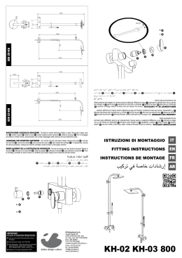
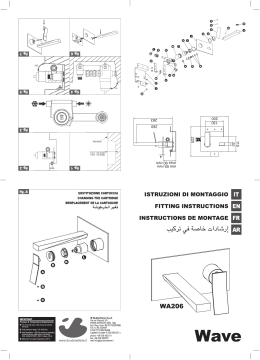
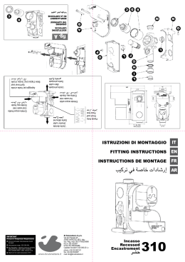
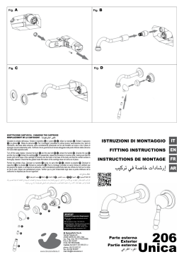
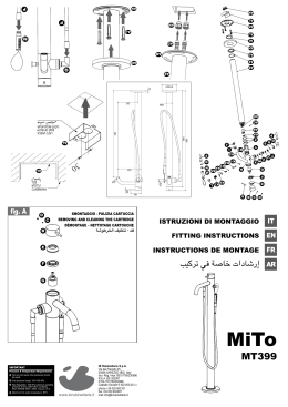
D
E
C
D
SOSTITUZIONE CARTUCCIA
CHANGING THE CARTRIDGE
REMPLACEMENT DE LA CARTOUCHE
g
b
i
f
a
Appoggio per livella a bolla
Spirit level seat
Base d’appui pour niveau à bulle
Parete finita
Finish wall
Paroi finie
Entrata acqua calda
Hot water inlet
Entrée eau chaude
Uscita
Outlet
Sortie
Entrata acqua fredda
Cold water inlet
Entrée eau froide
FITTING INSTRUCTIONS
INSTRUCTIONS DE MONTAGE
IMPORTANT
Pressure & Temperature Requirements.
• Hot and cold water inlet pressures should
be equal.
• Inlet pressure range: 150-1000 kPa
• New Regulation: -500 kPa maximum operating
pressure at any outlet within a building.
(Ref. AS/NZS 3500.1-2003, Clause 3.3.4)
• Maximum hot water temperature: 80°C.
iB Rubinetterie S.p.A.
Via dei Pianotti 3/5
25068 SAREZZO (BS) Italy
Iscr. Reg. Impr. BS 01785230986
R.E.A. BS 352087
P.IVA IT01785230986
Capitale Sociale € 420.000,00 i.v.
phone +39 030 802101
fax +39 030 803097
mail [email protected]
Incasso
Recessed
Encastrement
300
h
fig. A
C
ISTRUZIONI DI MONTAGGIO
LISTA DEI COMPONENTI
COMPONENTS LIST
A Vite acciaio M5 L65
D Cartuccia ceramica
G Tappo di protezione
A Inox screw M5 L65
D Ceramic cartridges
G Protection plug
B Coperchio di protezione
E Bicchiere cartuccia
H Bollino rosso
B Protection cover
E Cartridge housing
H Red label
C Ghiera premicartuccia
F Corpo in ottone incasso
I Bollino blu
C Cartridge locking nut
F Concealed brass body
I Blu label
DATI TECNICI
Pressione dinamica Min: Pressione Max di esercizio: Pressione di esercizio raccomandata: Si raccomanda di utilizzare un riduttore di pressione,
se all’interno dell’impianto si hanno pressioni statiche superiori a 5 bar.
Temperatura Max acqua calda: 0.5 bar
10 bar
1-5 bar
80°C
PROVE DI PORTATA
PRESSIONE bar
1
2
3
TECHNICAL DATA
Minimum dynamic pressure:
Maximum operational pressure:
Recommended operational pressure:
It is recommended to use a pressure reducer,
if inside the waterpipes there are static pressure superior to 5 bar
Maximumhot water temperature
0.5 bar
10 bar
1-5 bar
80°C
FLOW RATE TESTS
PORTATA L/MIN
CARTUCCIA Ø35
13
18
22.5
PORTATA L/MIN
CARTUCCIA Ø40
PRESSURE bar
16
23
28.5
1
2
3
FLOW RATE L/MIN
CARTRIDGE Ø35
FLOW RATE L/MIN
CARTRIDGE Ø40
13
18
22.5
16
23
28.5
NORME DI INSTALLAZIONE, MANUTENZIONE E VERIFICHE PRELIMINARI
Perché il suo apparecchio funzioni nella maniera corretta e possa durare nel tempo, occorre che vengano
rispettate le modalità di installazione e manutenzione illustrate in questo opuscolo. Affidarsi ad un idraulico
qualificato. Assicurarsi che l’impianto sia stato liberato da tutti i detriti e impurità esistenti.
INSTALLATION, MAINTENANCE AND PRELIMINARY CHECKING PROCEDURE
To ensure that the mixer tap unit functions correctly and lasts over time, the installation and maintenance
procedures illustrated in this leaflet must be complied with. Have all work done by a qualified plumber. Ensure that all debris and dirt have been removed from the system.
PULIZIA
Per una corretta pulizia, lavare esclusivamente con acqua e sapone, risciacquare ed asciugare con una
pelle di daino o panno morbido. Evitare assolutamente l’impiego di alcool, solventi, detersivi solidi o liquidi
contenenti sostanze corrosive o acide, strofinacci prodotti con fibre sintetiche, spugne abrasive e tamponi
con fili metallici, poiché potrebbero alterare irreversibilmente le superfici trattate.
CLEANING
To clean the unit correctly, use only soap and water, rinse and dry with a chamois leather or soft cloth.
Never use alcohol, solvents, solid or liquid detergents containing corrosive substances or acids, synthetic
fibre rags, abrasive sponges or steel wire scouring pads, since they may cause irreparable damage to the
treated surfaces.
INSTALLAZIONE
Posizionare il corpo miscelatore nell’alloggiamento praticato nella parete ponendo particolare attenzione
ai riferimenti per la posa MIN e MAX stampati sul coperchio di protezione B (N.B.: misure a parete finita
compreso rivestimento).
Estrarre i tappi in plastica G ed allacciarsi alle tubazioni della rete (entrata acqua calda e fredda) e all’uscita superiore. Dopo aver collegato il corpo incasso all’impianto, aprire i rubinetti d’arresto e verificare il
corretto funzionamento del miscelatore. Controllare la tenuta di tutti i collegamenti. Procedere poi con il
montaggio della piastra di copertura e della leva.
INSTALLATION
Place the body of the mixer tap unit in the cavity provided in the wall, taking care to refer to the MIN and
MAX installation markings printed on the protective cover B (N.B.: measurements refer to the finished
wall, complete with covering).
Remove the plastic plugs G and connect to the system pipes (hot and cold water intake) and the outlet at
the top. After connecting the body of the mixer tap unit to the system, turn on the stop taps and check that the
unit operates correctly. Check that all the connections are watertight. Then fit the cover plate and the lever.
SOSTITUZIONE CARTUCCIA (fig. A)
Chiudere le entrate dell’acqua fredda e calda. Svitare la ghiera premicartuccia C ed estrarre la cartuccia
D . Per il montaggio procedere in ordine inverso, assicurandosi che i perni di riferimento, alla base della
cartuccia siano correttamente posizionati nei fori del fondello interno al corpo e che il piano di appoggio sia
accuratamente pulito. Verificare che la guarnizione di tenuta alloggiata nella parte inferiore della cartuccia
non esca dalla apposita sede.
CHANGING THE CARTRIDGE (fig. A)
Turn off the hot and cold water intakes. Unscrew the retainer ring-nut C and remove the cartridge unit D .
To reassemble, repeat the procedure in reverse order, making sure that the locator pins at the base of the
cartridge fit correctly into the holes in the base of the body and that the contact surface is thoroughly cleaned.
Check that the gasket inside the bottom of the cartridge does not come out of place.
LISTE DES PIÈCES
A Vis acier M5 L65
D Cartouche céramique
G Bouchon de protection
A
D
G
B Couvercle de protection
E Logement cartouche
H Vignette rouge
B
E
H
I Vignette bleue
C
F
I
C Embout presse-cartouche F Corps en laiton encastrement
CARACTÉRISTIQUES TECHNIQUES
Pression dynamique mini.:
Pression maxi. d’exercice:
Pression d’exercice recommandée:
Il est recommandé d’utiliser un réducteur de pression en cas
de pressions statiques supérieures à 5 bars dans l’installation.
Température maxi. eau chaude:
M5 L65
0.5 bar
10 bar
1-5 bar
80°C
TESTS DE DÉBIT
PRESSION bar
1
2
3
DÉBIT L/MIN
CARTOUCHE Ø35
13
18
22.5
DÉBIT L/MIN
CARTOUCHE Ø40
16
23
28.5
/
35
1
2
3
/
40
13
18
22.5
16
23
28.5
NORMES D’INSTALLATION, D’ENTRETIEN ET VÉRIFICATIONS PRÉLIMINAIRES
Pour que votre appareil fonctionne correctement et dure dans le temps, il est nécessaire de respecter les
modalités d’installation et d’entretien illustrées dans cet opuscule. Demander l’intervention d’un plombier
qualifié. Vérifier que l’installation est libre de tous détritus et de toutes impuretés.
NETTOYAGE
Pour un nettoyage correct, laver exclusivement à l’eau savonneuse, rincer et essuyer avec une peau de
chamois ou un chiffon doux. Éviter l’emploi d’alcool, solvants, produits détergents solides ou liquides contenant des substances corrosives ou acides, les chiffons synthétiques, les éponges abrasives et les pailles
de fer, étant donné qu’ils peuvent endommager irrémédiablement les surfaces traitées.
INSTALLATION
Positionner le mélangeur dans le logement pratiqué dans la paroi en faisant très attention aux repères pour
la pose MIN et MAX présents sur le couvercle de protection B (N.B. : mesures à paroi finie, revêtement
compris).
Extraire les bouchons en plastique G et se raccorder aux tuyauteries du réseau (entrée eau chaude et
froide) et à la sortie supérieure. Après avoir relié le corps à encastrer à l’installation, ouvrir les robinets et
vérifier le fonctionnement correct du mélangeur. Contrôler l’étanchéité de tous les raccordements.
Procéder ensuite au montage de la plaque de couverture et du levier.
REMPLACEMENT DE LA CARTOUCHE (fig. A)
Fermer les entrées de l’eau froide et chaude. Dévisser l’embout presse-cartouche C et extraire la cartouche D . Pour le montage, procéder dans l’ordre inverse, en contrôlant si les repères, à la base de la
cartouche, sont correctement positionnés dans les orifices du fond à l’intérieur du corps et si le plan d’appui
est bien propre. Vérifier que le joint d’étanchéité situé dans la partie inférieure de la cartouche ne sorte
pas de son siège.
B
G
D
C
Scaricare