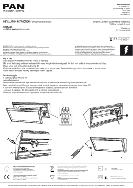
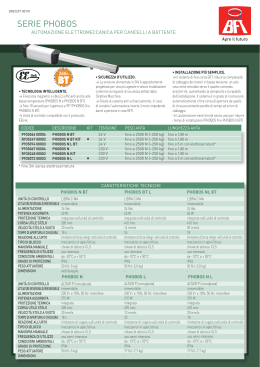
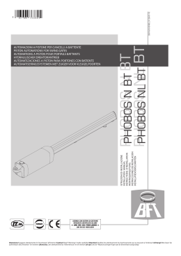
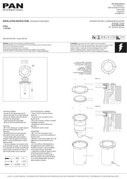
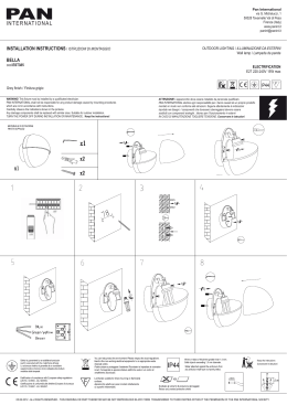
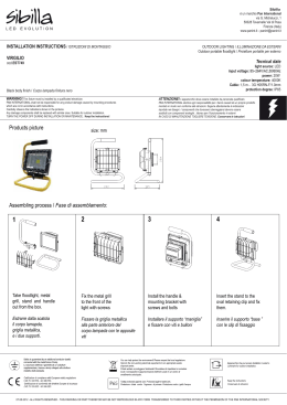
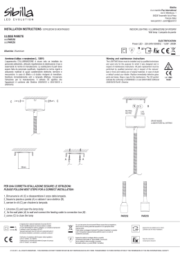
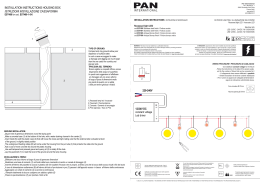
D811610 00100_01 28-01-10
PHOBOS
PHOBOS N N
BT BT
PHOBOS
PHOBOS NLNL
BT BT
ISTRUZIONI DI INSTALLAZIONE
INSTALLATION MANUAL
INSTRUCTIONS D’INSTALLATION
Montageanleitung
INSTRUCCIONES DE INSTALACION
INSTALLATIEVOORSCHRIFTEN
AUTOMAZIONI A PISTONE PER CANCELLI A BATTENTE
PISTON AUTOMATIONS FOR SWING GATES
AUTOMATIONS A PISTON POUR PORTAILS BATTANTS
HYDRAULISCHER DREHTORANTRIEB
AUTOMATIZACIONES A PISTON PARA PORTONES CON BATIENTE
AUTOMATISERINGSSYSTEMEN MET ZUIGER VOOR VLEUGELPOORTEN
Attenzione! Leggere attentamente le “Avvertenze” all’interno! Caution! Read “Warnings” inside carefully! Attention! Veuillez lire attentivement les Avertissements qui se trouvent à l’intérieur! Achtung! Bitte lesen Sie
aufmerksam die „Hinweise“ im Inneren! ¡Atención¡ Leer atentamente las “Advertencias” en el interior! Let op! Lees de “Waarschuwingen”tigre aan de binnenkant zorgvuldig!
D811610 00100_01
2 - PHOBOS N BT - PHOBOS NL BT
D811610 00100_01
PREDISPOSIZIONE TUBI, TUBE ARRANGEMENT, PRÉDISPOSITION DES TUYAUX,
VORBEREITUNG DER LEITUNGEN, DISPOSICIÓN DE TUBOS,
VOORBEREIDING LEIDINGEN.
2
2
5
,7
2x0
mm
m
5m
,
3x1
A
3x1
2
5
0,7
ITALIANO
INSTALLAZIONE VELOCE-QUICK INSTALLATION-INSTALLATION RAPIDE
SCHNELLINSTALLATION-INSTALACIÓN RÁPIDA - SNELLE INSTALLATIE
mm
5x
RG
mm2
3x1
m
58
2x1
,5
Q
mm2
,75
mm2
2x1
,5 m 2
m
2
,5
x1
R
mm
3x1
ENGLISH
2x0
m2
,5 m
m2
3
2
m
5m
,7
x0
5
SCHEMA D’INSTALLAZIONE. INSTALLATION DIAGRAM. SCHÉMA D’INSTALLATION.
INSTALLATIONSSCHEMA. ESQUEMA DE INSTALACIÓN. INSTALLATIESCHEMA.
B
x
S
F
FRANÇAIS
Z=b-x >45mm
D = MAX 1800mm (Phobos N BT)
D = MAX 5000mm (Phobos NL BT)
b
2S
hobos N BT)
C=700 mm (P
hobos NL BT)
C=825 mm (P
a
P
Phobos N BT
S
(mm)
125
kg
(~ 1250 N)
250
Phobos NL BT
kg
125
(~ 2500 N)
kg
b (mm)
20
30
40
50
3
b a 100 110 120 130 140 150 160 170 180
118
116
114
108 107
107 101
102 105 96
102 97 91
100 97 92 87
98 91 87 84
93 90 86 83
90 85 82
84 81
116 108 103
105 103 99
100 99 95
100 96 92
96 92
92 88
88
84
99
96
130 ÷ 160
130 ÷ 170
130 ÷ 180
130 ÷ 190
170 ÷ 260
180 ÷ 260
190 ÷ 260
200 ÷ 260
PHOBOS NL BT
b a 100 110 120 130 140 150 160 170 180 190 200 210 220 230
130
140
150
160
170
180
190
200
210
220
230
240
250
260
104
103
103
102
101
101
100
99
99
99
98
98
98
97
107
107
106
105
105
104
103
103
103
102
101
100
100
100
111
109
108
108
108
107
106
106
104
103
102
102
102
104
115
114
112
111
111
109
108
108
107
107
105
105
106
110
116
115
114
112
111
111
110
109
108
106
106
105
105
120
118
117
116
115
114
113
112
111
109
108
108
123
121
120
118
117
116
115
114
112
110
110
125
124
122
121
120
118
117
115
112
110
127
126
123
122
120
119
117
111
109
128
126
125
124
122
118
115
110
128
126
125
123
118
113
108
126
123
120
116
112
110
122
118
114
111
107
116
114
111
106
PHOBOS N BT - PHOBOS NL BT -
3
NEDERLANDS
100
110
120
130
140
150
160
170
180
190
200
210
(~ 2500 N)
b (mm)
130 ÷ 210
140 ÷ 210
150 ÷ 210
160 ÷ 210
PHOBOS N BT
kg
ESPAÑOL
2
100 ÷ 120
100 ÷ 130
100 ÷ 140
100 ÷ 150
250
(~ 1250 N)
DEUTSCH
1
kg
*
*
C
*
* Non in dotazione! Not provided! Pas fournis! Nicht mitgeliefert! No incluidos en el kit! Niet meegeleverd!
CAVO DI ALIMENTAZIONE. POWER CABLE. CÂBLE D’ALIMENTATION. NETZKABEL. CABLE DE ALIMENTACIÓN. VOEDINGSKABEL.
2
3
1
2 3
1
D
MOT MOT +
FC
40 mm
5 mm
3 x 1,5 mm2
Ø=7.1÷9.6
FISSAGGIO MOTORE SU ANCORAGGIO A PILASTRO. ATTACHING MOTOR TO
FASTENING ON PILLAR. FIXATION DU MOTEUR SUR L’ANCRAGGE SUR LE
PILIER. BEFESTIGUNG DES MOTORS AUF VERANKERUNG AM PFEILER.
FIJACIÓN MOTOR EN ANCLAJE AL PILAR. BEVESTIGING MOTOR OP
VERANKERING MET PIJLER.
E
MASSIMA INCLINAZIONE. MAXIMUM TILT.INCLINAISON
MAXIMUM. MAX. NEIGUNG. INCLINACIÓN MÁXIMA.
MAXIMUM HELLING.
F
+ 60 mm
- 60 mm
S1
R1
S1
2
Ø1
D1 M12
D1
R1
13
2,5
24
4 - PHOBOS N BT - PHOBOS NL BT
D811610 00100_01
ANCORAGGI DEGLI ATTACCHI AL PILASTRO. FASTENING OF FITTINGS TO PILLAR. ANCRAGES DES RACCORDEMENTS SUR LE PILIER.
VERANKERUNGEN DER ANSCCHLÜSSE AM PFEILER. ANCLAJES DE LAS FIJACIONES AL PILAR. VERANKERING VAN DE BEVESTIGINGEN AAN
DE PIJLER.
D811610 00100_01
CORRETTA INSTALLAZIONE. CORRECT INSTALLATION. INSTALLATION CORRECTE. RICHTIGE INSTALLATION. INSTALACIÓN CORRECTA.
CORRECTE INSTALLATIE.
G
CHIUDI
CLOSE
FERME
ÖFFNEN
CERRAR
SLUITEN
CHIUDI
CLOSE
FERME
ÖFFNEN
CERRAR
SLUITEN
PHOBOS N BT
PHOBOS NL BT
1
1
APRI
OPEN
OUVRE
SCHLIESSEN
ABRIR
OPENEN
APRI
OPEN
OUVRE
SCHLIESSEN
ABRIR
OPENEN
100 mm
135 mm
ANCORAGGI DEGLI ATTACCHI ALL’ANTA. FASTENING OF FITTINGS TO LEAF. ANCRAGES DES RACCORDEMENTS SUR LE VANTAIL.
VERANKERUNGEN DER ANSCHLÜSSE AM FLÜGEL. ANCLAJES DE LAS FIJACIONES A LA HOJA. VERANKERING VAN DE BEVESTIGINGEN AAN DE VLEUGEL.
*
FISSAGGIO OPERATORE
SULL’ANTA, OPERATOR
ATTACHMENT ON DOOR,
FIXATION DE L’ACTIONNEUR SUR
LE VANTAIL, BEFESTIGUNG DES
TRIEBS AM FLÜGEL, FIJACIÓN
OPERADOR EN LA HOJA, BEVESTIGING BEDIENING OP DE
VLEUGEL.
I
2
J
3
FC2 (CLOSE)
1
CHIUDI
CLOSE
FERME
ÖFFNEN
CERRAR
SLUITEN
2
Non in dotazione! Not provided! Pas fournis!
Nicht mitgeliefert! No incluidos en el kit! Niet meegeleverd!
REGOLAZIONE FINECORSA DI CHIUSURA, CLOSING LIMIT DEVICE ADJUSTMENT, RÉGLAGE DES FINS DE
COURSE DE FERMETURE, VERANKERUNG DER ANSCHLÜSSE AM FLÜGEL, REGULACIÓN DEL FIN DE CARRERA
DE CIERRE, AFSTELLING AANSLAG SLUITING.
1
H
3
~5
mm
A
B
A
REGOLAZIONE FINECORSA DI APERTURA, OPENING LIMIT DEVICE ADJUSTMENT, RÉGLAGE DE LA FIN DE COURSE D’OUVERTURE , EINSTELLUNG DES
ÖFFNUNGS-ENDSCHALTERS, REGULACIÓN DEL FIN DE CARRERA DE
APERTURA, AFSTELLING EINDAANSLAG OPENING.
~5
APRI
OPEN
OUVRE
SCHLIESSEN
ABRIR
OPENEN
K
mm
FC1 (OPEN)
PHOBOS N BT - PHOBOS NL BT -
5
102
825 Phobos N BT
943 Phobos NL BT
Cu MAX 305 mm Phobos N BT
Cu MAX 470 mm Phobos NL BT
72,5 mm Phobos N BT
108 mm Phobos NL BT
55
80
65
M
N
807 Phobos N BT
925 Phobos NL BT
962 Phobos N BT
1080 Phobos NL BT
b
b
a
P
O
b
1
b
1
6 - PHOBOS N BT - PHOBOS NL BT
Sinistra/Left/Gauche
Links/Izquierda
Esquerda
Destra/Right/Droite
Rechts/Derecha
Direita
1
D811610 00100_01
L
D811610 00100_01
GENERAL WARNINGS
WARNING! Important safety instructions. Carefully read and comply with
the Warnings booklet and Instruction booklet that come with the product as
incorrect installation can cause injury to people and animals and damage to
property. They contain important information regarding safety, installation,
use and maintenance.
CONTROL
There are various options when it comes to the control system (manual,
remote control, access control with magnetic badge, etc.) depending on
the installation’s needs and characteristics. See the relevant instructions for
the various control system options.
People due to use the automated device must be instructed how to control
and use it.
TROUBLESHOOTING
Gearbox malfunctioning
• Use an appropriate instrument to check for voltage across the gearbox
motor terminals after giving the opening or closing command.
If the motor vibrates but does not rotate, the problem may be:
• Incorrect wiring (see wiring diagram)
• If the leaf moves in the wrong direction, swap over the motor’s start
connections in the control unit.
The first command following a mains power outage should be open STOP
LEAVES.
SCRAPPING
Materials must be disposed of in conformity with the current regulations.
In case of scrapping, the automation devices do not entail any particular
risks or danger. In case of recovered materials, these should be sorted out
by type (electrical components, copper, aluminium, plastic etc.).
DISMANTLING
WARNING: before opening the door, the spring must be unloaded (vertical boom). When the automation system is disassembled to be reassembled
on another site, proceed as follows:
- Disconnect the power supply and the entire electrical installation.
- Remove the actuator from its fixing base.
- Disassemble all the installation components.
- In the case where some of the components cannot be removed or are
damaged, they must be replaced.
Correct controller operation is only ensured when the data contained in
the present manual are observed. The Company is not to be held responsible for any damage resulting from failure to observe the installation
standards and the instructions contained in the present manual.
The descriptions and illustrations contained in the present manual are
not binding. The Company reserves the right to make any alterations
deemed appropriate for the technical, manufacturing and commercial
improvement of the product, while leaving the essential product features unchanged, at any time and without undertaking to update the
present publication.
CHECKING INSTALLATION
Before the automated device is finally put into operation, perform the following checks meticulously:
• Make sure all components are fastened securely.
• Check that all safety devices (photocells, pneumatic safety edge, etc.) are
working properly.
• Check the emergency operation control device.
• Check opening and closing operations with the control devices applied.
• Check the electronic logic for normal (or personalized) operation in the
control panel.
ADJUSTING OPERATING FORCE
WARNING: Check that the force of impact measured at the points
provided for by standard EN 12445 is lower than the value laid
PHOBOS N BT - PHOBOS NL BT -
9
ENGLISH
1) GENERAL SAFETY
WARNING! An incorrect installation or improper use of the product can
cause damage to persons, animals or things.
• Scrap packing materials (plastic, cardboard, polystyrene etc) according
to the provisions set out by current standards. Keep nylon or polystyrene
bags out of children’s reach.
• Keep the instructions together with the technical brochure for future
reference.
• This product was exclusively designed and manufactured for the use
specified in the present documentation. Any other use not specified in
this documentation could damage the product and be dangerous.
• The Company declines all responsibility for any consequences resulting
from improper use of the product, or use which is different from that
expected and specified in the present documentation.
• Do not install the product in explosive atmosphere.
• The units making up the machine and its installation must meet the requirements of the following European Directives: 2004/108/EEC, 2006/95/
EEC, 2006/42/EEC, 99/05/EEC (and later amendments). For all countries
outside the EEC, it is advisable to comply with the above-mentioned
standards, in addition to any national standards in force, to achieve a
good level of safety.
• The Company declines all responsibility for any consequences resulting
from failure to observe Good Technical Practice when constructing closing structures (door, gates etc.), as well as from any deformation which
might occur during use.
• The installation must comply with the provisions set out by the following
European Directives: 2004/108/EEC, 2006/95/EEC, 2006/42/EEC, 99/05/
EEC and subsequent amendments.
• Disconnect the electrical power supply before carrying out any work on
the installation. Also disconnect any buffer batteries, if fitted.
• Fit an omnipolar or magnetothermal switch on the mains power supply,
having a contact opening distance equal to or greater than 3,5 mm.
• Check that a differential switch with a 0.03A threshold is fitted just before
the power supply mains.
• Fit all the safety devices (photocells, electric edges etc.) which are needed
to protect the area from any danger caused by squashing, conveying and
shearing, according to and in compliance with the applicable directives
and technical standards.
• Position at least one luminous signal indication device (blinker) where it
can be easily seen, and fix a Warning sign to the structure.
• The Company declines all responsibility with respect to the automation
safety and correct operation when other manufacturer’s components are
used.
• Only use original parts for any maintenance or repair operation.
• Do not modify the automation components, unless explicitly authorised
by the Company.
• Instruct the product user about the control systems provided and the
manual opening operation in case of emergency.
• Anything which is not expressly provided for in the present instructions,
is not allowed.
• Installation must be carried out using the safety devices and controls
prescribed by the EN 12978 Standard.
down by standard EN 12453.
Operating force is adjusted with extreme precision by means of the control
unit’s electronic control. Operation at the end of travel is adjusted electronically in the control panel.
To provide good anti-crush safety, the operating force must be slightly greater
than that required to move the leaf both to close and to open it. Whatever
the case, the force, which is measured at the top outer edge of the leaf, must
not exceed the limits laid down by the above-mentioned standards.
2) GENERAL INFORMATION
Electromechanical operator designed to automate residential-type gates.
The gearmotor keeps the gate locked on closing and on opening, without
needing an electric lock for leaves up to 3 m long. For leaves ranging between
3m and 5m long, the electric lock becomes indispensable.
The operator is provided with an electronic torque limiter. It must be controlled
by an electronic control panel provided with torque setting.
The end-of-stroke operation is controlled by two magnetic limit devices.
The operator is provided with an obstacle detection system complying with
EN12453 and EN 12445 standards.
8) POWER CABLE Fig. D
The board power supply cable must be of the H 05 RN-F type or equivalent.
The equivalent cable must guarantee:
- permanent outside use
- maximum temperature on the cable surface of +50° C
- minimum temperature of -25° C
The following optional accessories are available on request:
- Buffer battery kit mod. BT BAT
Allows operation of the automation even when there is no mains power
supply for a short period of time.
11) CORRECT INSTALLATION Fig. G
Correct installation entails maintaining a rod stroke margin of approx. 5-10
mm to avoid possible trouble with operation.
3) TECHNICAL SPECIFICATIONS
PHOBOS N - NL BT
Power supply
24V
Max. Absorbed power
40 W
Absorbed current
1,5 A
Push and pull force
2000 N (~200 kg)
Stem speed
15 mm/s approx.
Impact reaction
Torque limiter aboard control board
Limit devices
Magnetic, incorporated and adjustable
Manual manoeuvre
CLS release key
Environmental conditions
- 20°C a +50°C
Type of use
semi-intensive
Maximum leaf length without 1,8 m Phobos N BT
electric lock
3 m Phobos NL BT
Maximum leaf length with elec5 m Phobos NL BT
tric lock
Max. leaf weight
2500 N (~250 kg)
Protection level
IP X4
50N (~5kg) PHOBOS N BT
Controller weight
77N (~7,7kg) PHOBOS NL BT
Dimensions
See Fig. L
Lubrication
permanent grease
4) TUBE ARRANGEMENT Fig. A
Install the electrical system referring to the standards in force for electrical
systems CEI 64-8, IEC 364, harmonization document HD 384 and other
national standards.
5) INSTALLATION DIAGRAM Fig. B
P rear bracket fastening to pillar
F front fork fastening leaf
a-b distances for determining bracket “P” fastening point
C value of fastening centre-to-centre distance
D gate length
X distance from gate axis to corner of pillar
S half door thickness
Z value always greater than 45 mm (b - X)
kg max. weight of leaf
α° leaf opening angle
6) PILLAR FASTENINGS INSTALLATION DISTANCES Fig. B Rif. 2-3
6.1) How to read the installation distance tables
Select“a”and“b”according to the angle in degrees α° that the gate has to open.The
optimum “a” and “b” values for 92° opening at constant speed are highlighted.
If there is too large a difference between “a” and “b”, the leaf will not travel
smoothly and the pushing or pulling force will fluctuate during its stroke.
To respect the opening speed and ensure the controller operates correctly,
it is best to keep the difference between “a” and “b” as low as possible.
The table has been worked out for a 40 mm (PHOBOS NL BT), 20 mm (PHOBOS N BT) thick medium-size gate. Always check that there is no possible
collision between the gate and the operator.
7) FASTENING OF FITTINGS TO PILLAR Fig. C
10 - PHOBOS N BT - PHOBOS NL BT
9) ATTACHING MOTOR TO FASTENING ON PILLAR Fig. E
10) MAXIMUM TILT Fig. F
12) FASTENING OF FITTINGS TO LEAF Fig. H
IMPORTANT: the front bracket must be fitted with the bush collar protruding
UPWARDS (Fig. G Ref. 1).
13) OPERATOR ATTACHMENT ON DOOR Fig. I
14) Closing limit device adjustment Fig. J
ATTENTION! To avoid braking the limit switch cable, tighten screw A keeping
the wire B well tightened (as shown in Fig. J Rif. 3).
15) Opening limit device adjustment (Fig. K)
16) DIMENSIONS Fig. L
17) TIPS FOR SPECIAL INSTALLATIONS Fig. M, N, O.
With the leaf fully open, create a recess to accommodate the operator.
Fig. M gives the minimum dimensions of the recess for the various PHOBOS
N BT - PHOBOS N L BT models.
If distance “b” is greater than the values given in the installation tables:
- create a recess in the pillar Fig. N
- move the leaf so that it is flush with the pillar Fig. O.
18) LEAF STOPS AT GROUND LEVEL
For the actuator to work properly, it is advisable to use stops “Fig. P Rif. 1” to
stop the leaves both when they are open and closed, as illustrated in Fig.
P. The leaf stops must prevent the actuator rod from reaching the end of
its travel.
19) MANUAL OPENING (See USER GUIDE -FIG.Y-).
20) ELECTRIC LOCK
WARNING: In the case of leaves longer than 3m, it is indispensable
to install a solenoid latch.
For electric lock connection, the optional board is required (refer to the
appropriate instruction).
D811610 00100_01
INSTALLATION MANUAL
D811610 00100_01
MANUALE D’USO: MANOVRA DI EMERGENZA / USER GUIDE:EMERGENCY OPERATIONMANUEL D’UTILISATION: DE LA MANŒUVRE D’URGENCE / BEDIENUNGSHANDBUCH: NOTFALLMANÖVERMANUAL DE USO: MANIOBRA DE EMERGENCIA / GEBRUIKERSHANDLEIDING: NOODMANOEUVRE
FIG. Y
Senza Elettroserratura, Without electric lock, Sans serrure électrique, Ohne Elektroschloß, Sin electrocerradura, Zonder elektrische sluiting.
1
ON
2
ON
OFF
3
Con Elettroserratura, With electric lock, Avec serrure électrique, Mit Elektroschloß, Con electrocerradura, Met elektrische sluiting.
1
ON
2
3
ON
OFF
4
PHOBOS N BT - PHOBOS NL BT -
19
1) SICUREZZA GENERALE
ATTENZIONE Importanti istruzioni di sicurezza. Leggere e seguire attentamente l’opuscolo Avvertenze ed il Libretto istruzioni che accompagnano il prodotto poiché un uso improprio può causare danni a persone,
animali o cose. Conservare le istruzioni per consultazioni future.
Questo prodotto è stato progettato e costruito esclusivamente per l’utilizzo
indicato in questa documentazione. Usi non indicati potrebbero essere fonte
di danni al prodotto e fonte di pericolo.
- Gli elementi costruttivi della macchina e l’installazione devono essere
in accordo con le seguenti Direttive Europee: 2004/108/CE, 2006/95/CE,
2006/42/CE, 89/106/CE e loro modifiche successive. Per tutti i Paesi extra
CEE, oltre alle norme nazionali vigenti, per un buon livello di sicurezza è
opportuno rispettare anche le norme citate.
- La Ditta declina qualsiasi responsabilità derivante da un uso improprio o
diverso da quello per cui è destinato ed indicato nella presente documentazione nonché dall’inosservanza della Buona Tecnica nella costruzione
delle chiusure (porte, cancelli, ecc.) e dalle deformazioni che potrebbero
verificarsi durante l’uso.
L’automazione, se installata ed utilizzata correttamente, soddisfa il grado
di sicurezza richiesto. Tuttavia è opportuno osservare alcune regole di
comportamento per evitare inconvenienti accidentali:
- Tenere bambini, persone e cose fuori dal raggio d’azione dell’automazione,
in particolare durante il funzionamento.
- Poiché l’automazione può essere comandata a distanza e quindi non a
vista, è indispensabile controllare frequentemente la perfetta efficienza
di tutti i dispositivi di sicurezza.
- Quest’ applicazione non è destinata all’uso da parte di persone (inclusi i
bambini) con ridotte capacità mentali, fisiche e sensoriali, o persone che
mancano di conoscenze adeguate, a meno che non siano sotto supervisione o abbiano ricevuto istruzioni d’uso da persone responsabili della
loro sicurezza.
- I bambini devono essere controllati affinché non giochino con
l’applicazione. Non lasciare radiocomandi o altri dispositivi di comando
alla portata dei bambini onde evitare azionamenti involontari.
- Controllare spesso l’impianto, in particolare cavi, molle o supporti per
scoprire eventuali sbilanciamenti e segni di usura o danni.
- Per ogni operazione di pulizia esterna o altra manutenzione, togliere
l’alimentazione di rete
- Tenere pulite le ottiche delle fotocellule ed i dispositivi di segnalazione
luminosa. Controllare che rami ed arbusti non disturbino i dispositivi di
sicurezza (fotocellule).
- Non utilizzare l’automatismo se necessita di interventi di riparazione. In
caso di malfunzionamento, togliere l’alimentazione, attivare lo sblocco di
emergenza per consentire l’accesso e richiedere l’intervento di un tecnico
qualificato (installatore professionale).
- Per qualsiasi intervento diretto all’automazione, avvalersi di personale
qualificato (installatore professionale).
- Annualmente far controllare l’automazione da personale qualificato.
- Tutto quello che non è espressamente previsto in queste istruzioni, non
è permesso.
- ll buon funzionamento dell’operatore è garantito solo se vengono rispettati
i dati riportati in questo manuale. La ditta non risponde dei danni causati
dall’inosservanza delle norme di installazione e delle indicazioni riportate
in questo manuale.
- Le descrizioni e le illustrazioni del presente manuale non sono impegnative. Lasciando inalterate le caratteristiche essenziali del prodotto, la
Ditta si riserva di apportare in qualunque momento le modifiche che
essa ritiene convenienti per migliorare tecnicamente, costruttivamente e
commercialmente il prodotto, senza impegnarsi ad aggiornare la presente
pubblicazione.
20 - PHOBOS N BT - PHOBOS NL BT
USER’S MANUAL (GB)
Thank you for choosing this product. The Firm is confident that its performance will meet your operating needs. Carefully read the “WARNINGS” booklet
and “INSTRUCTION BOOKLET” that come with this product as they provide
important information regarding safety, installation, use and maintenance.
This product meets recognized technical standards and complies with safety
provisions. We hereby confirm that it is in conformity with the following
European directives: 2004/108/EEC, 2006/95/EEC, 2006/42/EEC, 99/05/EEC
(and later amendments).
1) GENERAL SAFETY
WARNING Important safety instructions. Carefully read and comply with
the Warnings booklet and Instruction booklet that come with the product
as improper use can cause injury to people and animals and damage to
property. Keep hold of instructions for future reference.
This product has been designed and built solely for the purpose indicated
herein. Uses not contemplated herein might result in the product being
damaged and could be a source of danger.
- The units making up the machine and its installation must meet the requirements of the following European Directives: 2004/108/EC, 2006/95/EC,
2006/42/EC, 89/106/EC and later amendments. For all countries outside the
EEC, it is advisable to comply with the standards mentioned, in addition
to any national standards in force, to achieve a good level of safety.
- The Firm disclaims all responsibility resulting from improper use or any
use other than that for which the product has been designed, as indicated
herein, as well as for failure to apply Good Practice in the construction of
entry systems (doors, gates, etc.) and for deformation that could occur
during use.
If installed and used correctly, the automated system will meet the required level of safety. Nonetheless, it is advisable to observe certain rules of
behaviour so that accidental problems can be avoided:
- Keep adults, children and property out of range of the automated system,
especially while it is operating.
- As automation can be remotely controlled and therefore not within sight,
it is essential to frequently check that all safety devices are perfectly
efficient.
- This application is not meant for use by people (including children) with
impaired mental, physical or sensory capacities, or people who do not have
suitable knowledge, unless they are supervised or have been instructed
by people who are responsible for their safety.
- Children must be supervised to ensure they do not play with the application. Keep remote controls or other control devices out of reach of children
in order to avoid the automated system being operated inadvertently.
- Check the system frequently, especially cables, springs or supports, to
detect any loss of balance and signs of wear or damage.
- When cleaning the outside or performing other maintenance work, always
cut off mains power.
- Keep the photocells’ optics and illuminating indicator devices clean.
Check that no branches or shrubs interfere with the safety devices (photocells).
- Do not use the automated system if it is in need of repair. In the event of
a malfunction, cut off the power, activate the emergency release to allow
access and call in qualified technical personnel (professional installer).
- If the automated system requires work of any kind, employ the services
of qualified personnel (professional installer).
- Have the automated system checked by qualified personnel once a
year.
- Anything that is not explicitly provided for in these instructions is not
allowed.
- The operator’s proper operation can only be guaranteed if the information
given herein is complied with. The Firm shall not be answerable for damage
caused by failure to comply with the installation rules and instructions
featured herein.
- Descriptions and illustrations herein are not binding. While we will not
alter the product’s essential features, the Firm reserves the right, at any
time, to make those changes deemed opportune to improve the product
from a technical, design or commercial point of view, and will not be
required to update this publication accordingly.
D811610 00100_01
MANUALE D’USO ( I )
Nel ringraziarVi per la preferenza accordata a questo prodotto, la Ditta è
certa che da esso otterrete le prestazioni necessarie al Vostro uso. Leggete
attentamente l’opuscolo “AVVERTENZE” ed il “LIBRETTO ISTRUZIONI” che
accompagnano questo prodotto in quanto forniscono importanti indicazioni riguardanti la sicurezza, l’installazione, l’uso e la manutenzione. Questo
prodotto risponde alle norme riconosciute della tecnica e della disposizioni
relative alla sicurezza. Confermiamo che è conforme alle seguenti direttive
europee: 2004/108/CEE, 2006/95/CEE, 2006/42/CEE, 99/05/CEE (e loro
modifiche successive).
Scaricare