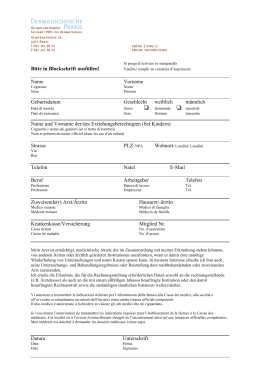
MOFB-MOFOB
photocells
Moonbus
Instructions and warnings for the fitter
Istruzioni ed avvertenze per l’installatore
Instructions et recommandations pour l’installateur
Anweisungen und Hinweise für den Installateur
Instrucciones y advertencias para el instalador
Instrukcje i uwagi dla instalatora
1) Warnings
! This manual has been especially written for use by qualified fitters. No information given in this manual can be considered as being of interest to end users!
This manual refers to MOFB-MOFOB only
and cannot be used for different products.
Read the instructions carefully before installing this
product. Improper use of the said product or
errors made during connection may jeopardise the
correct operation of the device and the safety of
the persons using it.
• The photocell must operate exclusively via
direct TX-RX interpolation. It must not be used
for reflection purposes.
• The photocell must be fastened securely to a
rigid surface, which does not vibrate.
• Use the wires specified in the manuals for control units for the electrical connections.
• The MOFB-MOFOB photocells can only be connected up to control units which use “BlueBus”
technology.
2) Description and Intended Use
communication system. This means they can easily be connected up to the control unit of all the
devices using two wires only. All the photocells are
quite simply connected in parallel, and the
addressing jumpers selected according to the
function required (see Table 1).
The non-adjustable version of the MOFB can be
used as long as the surface the device will be fastened to is flat and allows correct TX-RX centring.
The manufacturers recommend using the
adjutsable MOFOB version whenever this centring
is not directly possible.
! Only carry out installation work once
the electricity supply to the system has
been switched off. Disconnect any buffer
batteries present.
check that the surface the device will be fastened to will enable correct TX-RX centring.
Fasten the photocells as shown in Figures 1a
and 1b.
Begin the installation process by checking the following points:
1. As it is not possible to adjust the orientation
when using fixed MOFB photocells, fitters must
2. Position the photocells on the basis of their
detection functions according to the type of
automation used. Check the position in Figures
2, 3 and 4, and fit the jumpers as per Table 1.
3. Connect the electric cable to the appropriate TX
and RX terminals. From an electrical viewpoint,
TX and RX must be both connected in parallel
as shown in Figure 5, and to the “BlueBus” terminal of the interfaces or control units. It is not
necessary to observe any polarity.
The MOFB and MOFOB photocells are detectors
(type D according to EN standard 12453) which
can be used for automations for gates. They
reveal obstacles situated on the optical axis
between the transmitter (TX) and receiver (RX).
The photocells are equipped with a “BlueBus”
3) Installation
4) Addressing and recognition of devices
When addressing using the special jumpers, the
special “BlueBus” communication system enables
the control unit to recognise the photocells and
assign them with the correct detection function.
Addressing must be carried out on both the TX
and RX (and the jumpers set in the same way).
Ensure there are no other pairs of photocells with
the same address.
1. Address the photocells on the basis of the function required, setting the jumpers as shown in
Table 1. Any unused jumpers must be stored in
their proper compartment ready for future use,
as shown in Figure 6.
NOTE: Refer to the instruction manual for control
units and command interfaces with “BlueBus”
technology for a detailed description of the various
operations carried out for each kind of addressing.
NOTE (for FOTO 3): it is not normally necessary
to observe any restrictions in the position of the
pair of elements (TX-RX) that make up each photocell system; however, if photocell PHOTO 3 is
used in conjunction with photocell PHOTO II, the
positions illustrated in figure 7 must be observed.
2. Programme the devices using the control unit as
described in the paragraph entitled “Recognition
of connected devices” in the instruction manual of
the various “BlueBus” interfaces or control units.
2
Note: If the photocell is used to replace an already
existing one, the jumpers must be set exactly as
they were in the old photocell. It is not necessary
to carry out the recognition phase.
Table 1
Photocell
FOTO
3. Adjusting the orientation: it is possible to adjust
the orientation of the adjustable MOFOB photocell. This enables the user to achieve a perfect
alignment, even if the fastening is not excellent.
Proceed as per Figure 8 in order to regulate the
orientation. Loosen the screw slightly and move
the mobile part slowly. Then tighten the screw.
Follow the signals of the “L” indicator: the slower
the flashes, the better the centring.
The best centring has been achieved for both the
MOFB and MOFOB versions when the indicator
flashes very slowly, although performance is also
acceptable when flashes are simply slow. However, the centring is at risk when the indicator
flashes quickly.
FOTO II
FOTO 1
FOTO 1 II
FOTO 2
FOTO 2 II
FOTO 3
Jumpers
5) Testing and checking operation
After the recognition phase, check that the LED on the photocell starts flashing (both on TX and RX). Check Table 2 for the state of the photocell based on the
way LED “L” flashes.
GB
Table 2
LED “L”
Off
Status
The photocell is either not powered
or is faulty
Action
Make sure the voltage for the photocell terminals is
approximately 8-12 Vdc. If the voltage is correct, the photocell
is probably broken.
3 quick flashes and a
second’s pause
Very slow flashing
Repeat the learning procedure on the control unit. Make sure
that all the photocell pairs have different addresses
Normal operation
Slow flashing
Quick flashing
Device not recognised by the control
unit
The TX transmits regularly
The RX receives a perfect signal.
The RX receives a fair signal
The RX receives a poor signal
Very quick flashing
The RX receives a very poor signal
Always ON
The RX does not receive any signal
at all
L
Warning: After you have added or removed any
photocells, the automation system must be tested
again according to the directions contained in the
installation manual.
Normal operation
Normal operation. However, it is best to check the TX-RX
alignment and make sure the glasses are clean
It is at the very limit of normal operation. Check the TX-RX
alignment and make sure the glasses are clean.
Make sure that the LED on TX flashes once slowly. Check to
see if there is an obstacle between TX and RX. Check the TXRX alignment
To check the photocells and make sure that there
is no interference with other devices, pass a 5 cm
diameter, 30 cm long cylinder on the optical axis,
first near TX, then near RX and finally at the midpoint between them and make sure that in all
these cases the device is triggered, switching from
the active to the alarm status and vice-versa; finally, that it causes the intended action in the control
unit, for example that it causes the reversal of the
movement during the closing manoeuvre.
be cleaned, then testing carried out again, as
described in the previous paragraph.
The photocells have been studied and designed in
order that that they will operate in normal conditions for at least 10 years. It is, therefore, neces-
sary to increase the frequency of the maintenance
work carried out on the said photocells after this
period of time has elapsed.
This product is made from various kinds of material, some of which can be recycled. Make sure
you recycle or dispose of the product in compli-
ance with laws and regulations locally in force.
6) Maintenance
The photocells do not require any special maintenance work. However, it is necessary to check
them at least once every six months in order to
evaluate their condition (presence of damp,
oxides, etc.). The outer covering and lenses must
7) Disposal
! Warning: Some electronic substances may
contain polluting substances - do not dispose of
them in the environment.
8) Technical characteristics
Nice S.p.a., in order to improve its products, reserves the right to modify their technical characteristics at any time without prior notice. In any case, the
manufacturer guarantees their functionality and fitness for the intended purposes.
Note: all technical specifications refer to a temperature of 20°C.
Product type
Technology employed
Power supply/output
Absorbed power
Detection capacity
TX transmission angle
RX reception angle
Adjustability of the MOFOB photocell
Useful capacity
Maximum cable length
Addressing possibility
Use in acid, saline or potentially
explosive atmospheres
Mounting
Protection class for casing
Operating temperature
Dimensions / weight
Detector for gate and door automation systems (type D according to EN standard 12453), consisting in a “TX”
transmitter and “RX” receiver.
TX-RX direct optical interpolation with modulated infrared ray.
The device can only be connected to “BlueBus” networks, from which it receives its power supply and sends output
signals.
1 “BlueBus” unit.
Opaque objects (larger than 50 mm) located on the optical axis between TX and RX, which move more slowly than
1.6m/s.
20° +/- 25%
Approximately 20°.
Approximately 30° along the horizontal and vertical axes.
Up to 15m for a maximum TX-RX misalignment of ± 5° (the device can detect and signal an obstacle even in
particularly bad weather conditions).
Up to 50 m.
Up to 7 detectors with the protection function, and 2 with the opening command function.
The automatic synchronism prevents any interference among the various detectors.
No
Vertically wall-mounted
IP55
20 ÷55°C
for MOFB
69 x 78 h 25mm / 50g
for MOFOB 69 x 78 h 37mm / 75g
Nice S.p.a. reserves the right to modify its products at any time.
3
1) Avvertenze
! Il presente manuale è destinato solamente al personale tecnico qualificato per
l'installazione. Nessuna informazione contenuta nel presente fascicolo può essere
considerata d’interesse per l'utilizzatore
finale! Questo manuale è riferito alle fotocellule MOFB-MOFOB e non deve essere
utilizzato per prodotti diversi.
È opportuno leggere attentamente le istruzioni prima di eseguire l’installazione: l’uso improprio o un
errore di collegamento potrebbe pregiudicare la
sicurezza o il corretto funzionamento del dispositivo.
• La fotocellula deve funzionare esclusivamente
per interpolazione diretta TX-RX; è vietato l’uso
per riflessione.
• La fotocellula va fissata in modo permanente su
una superficie rigida e senza vibrazioni.
• Utilizzare per i collegamenti elettrici, conduttori
adeguati come riportato nei manuali delle centrali.
• Le fotocellule MOFB-MOFOB possono essere
collegate solo a centrali dotate di tecnologia
“BlueBus”.
2) Descrizione e destinazione d’uso
zione “BlueBus” che consente un facile collegamento alla centrale di tutti i dispositivi con soli due
fili. Le fotocellule vengono semplicemente collegate tutte in parallelo e, a seconda della funzione
richiesta, vengono selezionati i ponticelli di indirizzamento (vedere tabella 1).
La versione non orientabile MOFB è utilizzabile in
tutti quei casi, in cui le superfici di fissaggio sono
piane e permettano una corretta centratura TXRX; dove tale centratura non sia direttamente
possibile, si consiglia l’utilizzo della versione orientabile MOFOB.
! Tutte le operazioni d’installazione vanno eseguite in assenza di tensione all’impianto; nel caso sia presente la batteria
tampone, è necessario scollegarla.
mento occorre accertarsi che la superfici di fissaggio permettano una corretta centratura TXRX. Effettuare il fissaggio delle fotocellule come
indicato in fig. 1a e 1b.
Procedere con l’installazione, verificando i
seguenti punti:
1. Quando si utilizza la fotocellula fissa MOFB non
essendo disponibile la regolazione dell’orienta-
2. A seconda del tipo di automazione, posizionare
le fotocellule in base alle funzioni di rilevazione.
Verificare nelle figure 2, 3 e 4, le posizioni previste e porre i ponticelli secondo la tabella 1.
3. Collegare il cavo elettrico negli appositi morsetti
sia del TX che del RX. Dal punto di vista elettrico, TX ed RX vanno collegati in parallelo tra loro
(come mostrato nella figura 5) e al morsetto
“BlueBus” delle interfacce o centrali di comando. Non è necessario rispettare alcuna polarità
Le fotocellule MOFB e MOFOB sono rilevatori di
presenza (tipo D secondo la norma 12453) utilizzabili in automatismi per cancelli e permettono di
rilevare ostacoli presenti sull’asse ottico tra trasmettitore (TX) e ricevitore (RX).
Le fotocellule sono dotate di un tipo di comunica-
3) Installazione
4) Indirizzamento e apprendimento dei dispositivi
Il particolare sistema di comunicazione “BlueBus”
consente, tramite l’indirizzamento con gli appositi
ponticelli, il riconoscimento delle fotocellule da
parte della centrale e di assegnare la corretta funzione di rilevazione. L’operazione di indirizzamento
va fatta sia sul TX che sul RX (ponendo i ponticelli
nello stesso modo) verificando che non vi siano
altre coppie di fotocellule con lo stesso indirizzo.
1. Indirizzare le fotocellule in base alla funzione
richiesta ponendo i ponticelli secondo la tabella 1.
Riporre gli eventuali ponticelli non usati nel vano
riservato per utilizzi futuri, come in figura 6
Nota: Per la descrizione dettagliata delle varie funzioni eseguite ad ogni tipo di indirizzamento, si
rimanda ai manuali d’uso delle centrali e interfacce di comando con tecnologia “BlueBus”.
Nota per fotocellula “FOTO 3”: normalmente
non è necessario rispettare alcun vincolo nella
posizione dei due elementi che compongono la
fotocellula (TX-RX). Solo nel caso venga utilzzata
la fotocellula “FOTO 3” assieme alla fotocellula
“FOTO II” è necessario rispettare la posizione degli
elementi come indicato in figura 7.
2. Sulla centrale, eseguire la procedura di programmazione dei dispositivi, come riportato nel
paragrafo “Apprendimento dispositivi collegati”
nel manuale d’uso delle varie interfacce o centrali di comando “BlueBus”.
4
Nota: Se la fotocellula viene usata in sostituzione
di una già esistente, i ponticelli andranno posti
esattamente com’erano nella fotocellula sostituita
e non è necessaria la fase di apprendimento.
Tabella 1
Fotocellula
FOTO
3. Regolazione dell’orientamento: Nella fotocellula
orientabile MOFOB è disponibile la regolazione
dell’orientamento che consente di ottenere un
perfetto allineamento anche quando il fissaggio
non è ottimale. Per regolare l’orientamento procedere come indicato in figura 8. Allentare leggermente la vite e far oscillare lentamente la parte mobile, infine richiudere la vite. Seguire la
segnalazione dell’indicatore “L”: minore è la
velocità del lampeggio e migliore è la centratura. Su entrambe le versioni MOFB e MOFOB, la
centratura ottimale si ha quando l’indicatore
lampeggia molto lentamente, comunque accettabile quando lampeggia lentamente, a rischio
invece quando l’indicatore lampeggia velocemente.
FOTO II
FOTO 1
FOTO 1 II
FOTO 2
FOTO 2 II
FOTO 3
Ponticelli
5) Collaudo e verifica del funzionamento
Dopo la fase di apprendimento verificare che il LED sulla fotocellula esegua dei lampeggi (sia su TX che RX). Verificare in tabella 2 lo stato della fotocellula in
base al tipo di lampeggio del led “L”.
Tabella 2
L
LED “L”
Spento
Stato
La fotocellula non è alimentata
oppure è guasta
3 lampeggi veloci e 1
secondo di pausa
Dispositivo non appreso dalla
centrale di comando
Lampeggio molto lento
Lampeggio lento
Lampeggio veloce
Il TX trasmette regolarmente.
L’RX riceve un segnale ottimo
L’RX riceve un segnale buono
L’RX riceve un segnale scarso
Lampeggio velocissimo
L’RX riceve un segnale pessimo
Sempre acceso
L’RX non riceve alcun segnale
Attenzione: dopo aver aggiunto o sostituito delle
fotocellule è necessario eseguire nuovamente il
collaudo dell’intera automazione secondo quanto
previsto nei relativi manuali di installazione.
Azione
Verificare che sui morsetti della fotocellula sia presente una
tensione di circa 8–12 Vdc; se la tensione è corretta è probabile
che la fotocellula sia guasta
Ripetere la procedura di apprendimento dalla centrale.
Verificare che tutte le coppie di fotocellula abbiano indirizzi
diversi
Funzionamento normale
I
Funzionamento normale
Funzionamento normale ma è il caso di verificare l'allineamento
TX-RX e la corretta pulizia dei vetrini
É al limite del funzionamento normale, occorre verificare
l'allineamento TX-RX e la corretta pulizia dei vetrini
Verificare che il LED sul TX esegua un lampeggio molto lento.
Verificare se c’è un ostacolo tra TX e RX; verificare
l’allineamento TX - RX
Per la verifica delle fotocellule ed in particolare che
non vi siano interferenze con altri dispositivi, passare un cilindro di diametro 5cm e lunghezza
30cm sull’asse ottico prima vicino al TX, poi vicino
al RX e infine al centro tra i due e verificare che in
tutti i casi il dispositivo intervenga passando dallo
stato di attivo a quello di allarme e viceversa; infine che provochi nella centrale l’azione prevista; ad
esempio: nella manovra di chiusura provochi l’inversione di movimento
venga quindi eseguita la pulizia dell’involucro
esterno e delle lenti, e rieseguito il collaudo come
descritto al paragrafo precedente. Le fotocellule
sono state studiate per funzionare in condizioni
normali almeno 10 anni, è quindi opportuno intensificare la frequenza di manutenzione trascorso
questo periodo.
Questo prodotto è costituito da varie tipologie di
materiali, alcuni possono essere riciclati. Informatevi sui sistemi di riciclaggio o smaltimento del
prodotto attenendosi alle norme di legge vigenti a
livello locale.
6) Manutenzione
Le fotocellule non necessitano di accorgimenti
particolari, ma è necessaria un controllo almeno
ogni 6 mesi nella quale venga verificato lo stato
delle stesse (presenza di umidità, ossidi, ecc.),
7) Smaltimento
! Attenzione: alcuni componenti potrebbero
contenere sostanze inquinanti, non disperdere
nell’ambiente.
8) Caratteristiche tecniche
Allo scopo di migliorare i prodotti, NICE S.p.a. si riserva il diritto di modificare le caratteristiche tecniche in qualsiasi momento e senza preavviso, garantendo
comunque funzionalità e destinazione d’uso previste.
Nota: tutte le caratteristiche tecniche sono riferite alla temperatura di 20°C.
Tipo di prodotto
Tecnologia adottata
Alimentazione/uscita
Potenza assorbita
Capacità di rilevamento
Angolo di trasmissione TX
Angolo di ricezione RX
Orientabilità della fotocellula MOFOB
Portata utile
Lunghezza massima cavi
Possibilità di Indirizzamento
Utilizzo in atmosfera acida, salina o
potenzialmente esplosiva
Montaggio
Grado di protezione contenitore
Temperatura di esercizio
Dimensioni / peso
Rilevatore di presenza per automatismi di cancelli e portoni automatici (tipo D secondo
norma EN 12453) composto da una coppia di trasmettitore “TX” e ricevitore “RX”
Interpolazione ottica diretta TX-RX con raggio infrarosso modulato
Il dispositivo può essere collegato solo a reti “BlueBus” dalla quale preleva l’alimentazione
elettrica e invia i segnali di uscita.
1 unità Blue bus
Oggetti opachi posti sull’asse ottico tra TX-RX con dimensioni maggiori di 50mm e velocità
minore di 1,6m/s
20° +/- 25%
20° circa
30° circa nei due assi orizzontale e verticale
Fino a 15m per disassamento TX-RX massimo ± 5° (il dispositivo può segnalare un ostacolo
anche in caso di condizioni metereologiche particolarmente avverse)
Fino a 50 m
Fino a 7 rilevatori con funzione di protezione e 2 con funzione di comando di apertura.
Il sincronismo automatico evita l’interferenza fra i vari rilevatori
No
Verticale a parete
IP55
20 ÷55°C
per MOFB
69 x 78 h 25mm / 50g
per MOFOB 69 x 78 h 37mm / 75g
Nice S.p.a. si riserva il diritto di apportare modifiche ai prodotti in qualsiasi momento riterrà necessario
5
1) Avertissements
! Ce manuel est destiné exclusivement
au personnel technique qualifié pour l’installation; aucune information contenue
dans ce fascicule ne peut être considérée
comme intéressante pour l’utilisateur
final!
Ce manuel se réfère aux photocellules
MOFB-MOFOB et ne doit pas être utilisé
pour des produits différents.
Il est opportun de lire attentivement les instructions
avant d’effectuer l’installation: l’utilisation impropre
ou une erreur de connexion pourrait compromettre
le fonctionnement correct du dispositif.
• La photocellule doit fonctionner exclusivement
par interpolation directe TX-RX; l’utilisation par
réflexion est interdite.
• La photocellule doit être fixée de façon permanente sur une surface rigide et sans vibrations.
• Utiliser pour les connexions électriques des
conducteurs adéquats conformément aux indications données dans les manuels des logiques
de commande.
• Les photocellules MOFB-MOFOB peuvent être
connectées uniquement à des logiques de
commande avec technologie “BlueBus”.
Les photocellules sont munies d’un type de communication “BlueBus” qui permet une connexion
aisée de tous les dispositifs à la logique de commande en n’utilisant que deux fils. Les photocellules sont simplement connectées toutes en parallèle et les cavaliers d’adressage sont sélectionnés
suivant la fonction demandée (voir tableau 1).
La version non orientable MOFB est utilisable
dans tous les cas où les surfaces de fixation sont
planes et permettent un centrage TX-RX correct;
quand ce centrage n’est pas possible directement, il est conseillé d’opter pour la version orientable MOFOB.
un centrage TX-RX correct.
Effectuer la fixation des photocellules comme
l’indiquent les fig. 1a et 1b.
3. Connecter le câble électrique dans les bornes
prévues à cet effet tant du TX que du RX. Du
point de vue électrique, TX et RX doivent être
connectés en parallèle entre eux (comme l’indique la figure 5) et à la borne “BlueBus” des
interfaces ou des logiques de commande.
Il n’est pas nécessaire de respecter une polarité
quelconque
2) Description et application
Les photocellules MOFB et MOFOB sont des
détecteurs de présence (type D selon la norme
12453) utilisables dans des automatismes pour
portails et permettent de détecter des obstacles
présents sur l’axe optique entre l’émetteur (TX) et
le récepteur (RX).
3) Installation
! toutes les opérations d’installation
sont effectuées sans tension dans l’installation; si la batterie tampon est présente,
il faut la déconnecter.
Procéder à l’installation en vérifiant les points suivants:
1. Quand on utilise la photocellule fixe MOFB, le
réglage de l’orientation n’étant pas disponible, il
faut s’assurer que la surface de fixation permet
2. Suivant le type d’automatisme, positionner les
photocellules suivant les fonctions de détection.
Sur les figures 2, 3 et 4, vérifier les positions prévues et mettre les cavaliers comme l’indique le
tableau 1.
4) Adressage et apprentissage des dispositifs
Le système particulier de communication “BlueBus” permet, à travers l’adressage à l’aide des
cavaliers, la reconnaissance des photocellules de
la part de la logique et d’attribuer la fonction de
détection correcte. L’opération d’adressage doit
être faite tant sur le TX que sur le RX (en mettant
les cavaliers dans la même position) en vérifiant
qu’il n’y a pas d’autres paires de photocellules
ayant la même adresse.
1. Adresser les photocellules suivant la fonction
demandée en positionnant les cavaliers comme
l’indique le tableau 1.
Remettre les cavaliers inutilisés dans le logement réservé pour des utilisations futures, comme sur la figure 6.
Note: Pour la description détaillée des diverses
fonctions exécutées à chaque type d’adressage,
nous renvoyons aux manuels d’instructions des
logiques de commande et interfaces de commande avec technologie “BlueBus”.
Note pour photocellule “FOTO 3”: normalement il n’y a aucune contrainte à respecter dans la
position des deux éléments qui composent la
photocellule (TX-RX). Seulement si l’on utilise la
photocellule “FOTO 3” avec la photocellule “FOTO
II” il faut respecter la position des éléments indiquée dans la figure 7.
6
2. Sur la logique de commande, effectuer la procédure de programmation des dispositifs comme l’indique le paragraphe “Apprentissage dispositifs connectés” dans le manuel d’instructions des diverses interfaces ou logiques de
commande “BlueBus”.
Note: si la photocellule est utilisée à la place d’une
pré-existante, les cavaliers devront être positionnés exactement comme ils l’étaient pour la photocellule remplacée et la phase d’apprentissage
n’est pas nécessaire.
3. Réglage de l’orientation: la photocellule orientable MOFOB dispose du réglage de l’orientation qui permet d’obtenir un alignement parfait
même quand la fixation n’est pas parfaite. Pour
régler l’orientation, procéder comme l’indique la
figure 8. Desserrer légèrement la vis et faire
osciller lentement la partie mobile, puis serrer
enfin la vis. Suivre la signalisation de la led “L”:
plus le clignotement est lent et meilleur est le
centrage. Sur les deux versions MOFB et
MOFOB, le centrage idéal s’obtient quand la led
clignote très lentement, il est acceptable toutefois quand elle clignote lentement, mais est par
contre à risque quand elle clignote rapidement.
Tableau 1
Photocellule
FOTO
FOTO II
FOTO 1
FOTO 1 II
FOTO 2
FOTO 2 II
FOTO 3
Cavaliers
5) Essai et contrôle du fonctionnement
Après la phase d’apprentissage, vérifier que la led sur la photocellule effectue des clignotements (tant sur TX que sur RX). Vérifier dans le tableau 2 l’état de la
photocellule suivant le type de clignotement de la led “L”.
Tableau 2
LED “L”
Éteinte
L
État
La photocellule n’est pas alimentée
ou est en panne
3 clignotements rapides et 1 Ce dispositif n’a pas été mémorisé
seconde de pause
par la logique de commande
Clignotement très lent
Clignotement lent
Clignotement rapide
Le
Le
Le
Le
Clignotement très rapide
Le RX reçoit un très mauvais signal
Toujours allumée
Le RX ne reçoit aucun signal
Attention: après avoir ajouté ou remplacé des
photocellules il faut effectuer de nouveau l’essai
de tout l’automatisme suivant ce qui est prévu
dans les manuels d’installation correspondants.
TX transmet régulièrement
RX reçoit un excellent signal
RX reçoit un bon signal
RX reçoit un signal faible
Action
Vérifier qu’aux bornes de la photocellule arrive une tension
d’environ 8–12 Vcc; si la tension est correcte, la photocellule
est probablement en panne.
Répéter la procédure d’apprentissage de la logique de
commande. Vérifier que toutes les paires de photocellules ont
bien des adresses différentes
Fonctionnement normal
Fonctionnement normal
Fonctionnement normal mais il est bon de vérifier l’alignement
TX-RX et la propreté des verres
On est à la limite du fonctionnement normal, il faut vérifier
l’alignement TX-RX et la propreté des verres
Vérifier que la led sur le TX clignote très lentement. Vérifier s’il y
a un obstacle entre TX et RX; vérifier l’alignement TX - RX
Pour le contrôle des photocellules et en particulier
pour vérifier qu’il n’y a pas d’interférences avec
d’autres dispositifs, passer un cylindre d’un diamètre de 5 cm et d’une longueur de 30 cm sur
l’axe optique, d’abord à proximité de TX, puis de
RX, et enfin au centre entre les deux et vérifier que
dans tous les cas, le dispositif intervient en passant de l’état d’actif à l’état d’alarme et vice versa;
contrôler qu’il provoque l’action prévue dans la
logique, par exemple: dans la manœuvre de fermeture, qu’il provoque l’inversion de mouvement.
etc.), procéder au nettoyage du boîtier extérieur et
des verres puis refaire le contrôle décrit au paragraphe précédent. Les photocellules ont été étudiées pour fonctionner dans des conditions nor-
males au moins 10 ans, il est donc recommandé
d’intensifier la fréquence des contrôles de maintenance passée cette période
Ce produit est constitué de différents types de
matériaux dont certains peuvent être recyclés.
Informez-vous sur les systèmes de recyclage ou
de mise au rebut du produit en respectant les
normes locales en vigueur.
F
6) Maintenance
Les photocellules ne nécessitent pas de précautions particulières, mais un contrôle est nécessaire au moins tous les 6 mois au cours duquel il faut
vérifier leur état (présence d’humidité, oxydes,
7) Mise au rebut
! Attention: Certains composants électroniques pourraient contenir des substances polluantes, ne pas les abandonner dans la nature.
8) Caractéristiques techniques
Dans le but d’améliorer ses produits, NICE S.p.A. se réserve le droit de modifier les caractéristiques techniques à tout moment et sans préavis, en garantissant dans tous les cas le bon fonctionnement et le type d’utilisation prévus..
N.B.: toutes les caractéristiques techniques se réfèrent à la température de 20°C.
Type de produit
Détecteur de présence pour automatismes de portails et portes automatiques (type D
selon norme EN 12453) composé d’une paire: émetteur “TX” + récepteur “RX”
Technologie adoptée
Interpolation optique directe TX-RX avec rayon infrarouge modulé
Alimentation/sortie
Le dispositif ne peut être connecté qu’à des circuits “BlueBus” d’où il prélève l’alimentation
électrique et envoie les signaux de sortie
Puissance absorbée 1 unité Blue bus
Capacité de détection
Objets opaques situés sur l’axe optique entre TX-RX de dimensions supérieures à 50 mm et
vitesse inférieure à 1,6 m/s
Angle de transmission TX
20° +/- 25%
Angle de réception RX
20° environ
Possibilité d'orientation de la
30° environ dans les deux axes horizontal et vertical
photocellule MOFOB
Portée utile
Jusqu’à 15 avec un désalignement TX-RX maximum de ± 5° (le dispositif peut signaler un
obstacle même en cas de conditions météorologiques particulièrement critiques)
Longueur maximum des câbles
Jusqu’à 50 m
Possibilité d’adressage
Jusqu’à 7 détecteurs avec fonction de protection et 2 avec fonction de commande
d’ouverture. Le synchronisme automatique évite l’interférence entre les différents détecteurs.
Utilisation en atmosphère acide, saline ou
Non
potentiellement explosive
Montage
Vertical au mur
Indice de protection boîtier
IP55
Température de service
20 ÷55°C
Dimensions / poids
pour MOFB
69 x 78 h 25mm / 50g
pour MOFOB 69 x 78 h 37mm / 75g
Nice S.p.a. se réserve le droit d’apporter des modifications aux produits à tout moment si elle le jugera nécessaire.
7
1) Hinweise
! Die vorliegende Anleitung ist nur für
technisches Personal bestimmt, das für
die Installation qualifiziert ist. Keine im
vorliegenden Heft enthaltene Information
kann als interessant für den Endbenutzer
betrachtet werden!
Die vorliegende Anleitung bezieht sich auf
die Photozellen MOFB-MOFOB und darf für
andere Produkte nicht benutzt werden.
Vor Beginn der Installation müssen alle Anweisungen genau gelesen werden: unsachgemäße
Bedienung oder Anschlussfehler könnten die
Sicherheit oder den korrekten Betrieb der Vorrichtung beeinträchtigen.
• Die Photozelle darf ausschließlich durch direkte
Interpolation von TX und RX funktionieren; der
Gebrauch durch Reflexion ist verboten.
• Die Photozelle muss bleibend auf einer festen
und vibrationsfreien Fläche angebracht werden.
• Für die elektrischen Anschlüsse geeignete Leiter
verwenden, wie in den Anleitungen der Steuerungen angegeben.
• Die Photozellen MOFB-MOFOB können nur an
Steuerungen mit “BlueBus” Technologie angeschlossen werden.t
Für einen leichten Anschluss aller Vorrichtungen
an der Steuerung mit nur zwei Drähten sind die
Photozellen mit “BlueBus” Kommunikation ausgestattet. Alle Photozellen werden einfach parallel
geschaltet, und je nach der gewünschten Funktion wählt man dann die Adressierungsbrücken
(siehe Tabelle 1).
Die nicht schwenkbare Ausführung MOFB wird
überall benutzt, wo die Befestigungsflächen eben
sind und TX mit RX korrekt zentriert werden kann.
Falls eine solche Zentrierung nicht direkt möglich
ist, wird die Benutzung der schwenkbaren Ausführung MOFOB empfohlen.
dass die Befestigungsfläche ein korrektes Zentrieren von TX mit RX ermöglicht. Die Photozellen wie in Abb. 1a und 1b befestigen.
3. Das Stromkabel an den dazu vorgesehenen
Klemmen von TX und RX anschließen. TX und
RX müssen miteinander und mit der “BlueBus”
Klemme der Schnittstellen bzw. Steuerungen
parallelgeschaltet werden (wie in Abbildung 5
gezeigt). Eine Polung ist nicht zu beachten.
2) Beschreibung und Einsatz
Die Photozellen MOFB und MOFOB sind Präsenzdetektoren (Typ D gemäß Norm 12453), die an
Torautomatismen benutzt werden können und es
ermöglichen, Hindernisse auf der optischen Achse
zwischen Sender (TX) und Empfänger (RX) wahrzunehmen.
3) Installation
! Alle Installationsarbeiten müssen ohne
Spannung zur Anlage ausgeführt werden;
die Pufferbatterie muss, falls vorhanden,
abgetrennt werden.
Die Installation nach Überprüfung folgender Punkte durchführen:
1. Bei Benutzung der festen Photozelle MOFB, die
nicht verstellt werden kann, ist sicher zu stellen,
2. Die Photozellen je nach Automatisierung und
den erforderlichen Funktionen positionieren.
Die vorgesehenen Positionen in den Abbildungen 2, 3 und 4 überprüfen und die Überbrückungen gemäß Tabelle 1 ausführen.
4) Adressierung und Erlernung der Vorrichtungen
Dank dem besonderen “BlueBus” Kommunikationssystem erkennt die Steuerung die Photozellen
durch Adressierung mit speziellen Überbrückungen und den Photozellen werden die korrekten
Detektionsfunktionen zugeteilt. Die Adressierung
muss sowohl an TX als auch an RX ausgeführt
werden (die Überbrückungen müssen an TX und
an RX gleich sein). Weiter ist zu prüfen, dass keine anderen Photozellenpaare mit derselben
Adressierung vorhanden sind.
1. Die Photozellen je nach ihrer Funktion adressieren und die Überbrückungen gemäß Tabelle 1
ausführen. Nicht benutzte Überbrückungen im
dazu vorgesehenen Raum unterbringen, gemäß
Abbildung 6.
Anmerkung: für eine genauere Beschreibung der
verschiedenen Funktionen jeder Adressierung
wird auf die Bedienungsanleitungen der Steuerungen oder Schnittstellen mit “BlueBus” .
Anmerkung für die Photozelle “FOTO 3”:
gewöhnlich müssen die beiden Photozellenelemente TX und RX in keiner besonderen Position
sein. Nur wenn die Photozelle “FOTO 3” zusammen mit der Photozelle “FOTO II” benutzt wird,
müssen die Elemente die in Abbildung 7 gezeigte
Position haben.
8
2. An der Steuerung das Programmierverfahren
der Vorrichtungen ausführen, wie in Abschnitt
“Erlernung der angeschlossenen Vorrichtungen”
in der Anleitung der verschiedenen “BlueBus”
Schnittstellen oder Steuerungen angegeben.
Anmerkung: Falls die Photozelle als Ersatz einer
bereits vorhandenen Photozelle benutzt wird,
müssen die Überbrückungen genau wie jene der
ersetzten Photozelle ausgeführt werden; eine
Erlernung ist in diesem Fall nicht erforderlich.
Tabelle 1
Photozelle
FOTO
FOTO II
FOTO 1
3. Verstellung der schwenkbaren Photozellen
MOFOB: Diese Ausführung kann für eine einwandfreie Fluchtung auf nicht optimaler Unterlage geschwenkt werden. Hierzu wie in Abbildung
8 gezeigt vorgehen. Die Schraube etwas
lockern und den beweglichen Teil langsam
schwenken, danach die Schraube wieder festziehen. Den Meldungen der LED “L” folgen: je
langsamer die LED blinkt, desto besser ist die
Zentrierung. Für beide Ausführungen MOFB
und MOFOB ist die Zentrierung optimal, wenn
die LED sehr langsam blinkt; ein langsames
Blinken ist akzeptierbar, ein schnelles Blinken
weist dagegen auf eine schlechte Zentrierung
hin.
FOTO 1 II
FOTO 2
FOTO 2 II
FOTO 3
Überbrückungen
5) Endprüfung und Betriebstest
Nach der Erlernung prüfen, dass die LED an der Photozelle blinkt (an TX und an RX). Den Status der Photozelle je nachdem, wie die LED “L” blinkt, in Tabelle
2 überprüfen.
Tabelle 2
LED “L”
Aus
L
3 Mal Schnellblinken und 1
Sekunde Pause
Sehr langsames Blinken
Langsames Blinken
Schnellblinken
Sehr schnelles Blinken
Leuchtet immer
Achtung: Nachdem Photozellen hinzugefügt bzw.
ersetzt worden sind, muss die Endprüfung der
gesamten Automatisierung gemäß den entsprechenden Installationsanleitungen erneut ausgeführt
werden.
Status
Photozelle nicht gespeist oder defekt
Handlung
Prüfen, dass an den Klemmen der Photozelle eine Spannung
von ca. 8–12 Vdc anliegt; im Falle einer korrekten Spannung ist
die Photozelle wahrscheinlich defekt
Keine Erlernung der Vorrichtung durch Das Erlernverfahren von der Steuerung aus wiederholen.
Prüfen, dass alle Photozellenpaare unterschiedlich adressiert
die Steuerung
sind.
Normalbetrieb
TX überträgt ordnungsgemäß.
RX empfängt ein optimales Signal
RX empfängt ein gutes Signal
Normalbetrieb
RX empfängt ein schlechtes Signal
Normalbetrieb, man sollte jedoch die Fluchtung von TX mit RX
und die Sauberkeit der Gläser überprüfen.
Ist an der Grenze des Normalbetriebs; die Fluchtung von TX
RX empfängt ein sehr schlechtes
Signal
und RX und Sauberkeit der Gläser überprüfen
RX empfängt gar kein Signal
Prüfen, ob die LED an TX ein sehr langsames Blinken ausführt.
Prüfen, ob ein Hindernis zwischen TX und RX vorhanden ist.
Die Fluchtung von TX und RX überprüfen.
Zur Überprüfung der Photozellen und insbesondere
von Interferenzen mit anderen Vorrichtungen, einen
Zylinder mit 5 cm Durchmesser und 30 cm Länge
auf der optischen Achse zuerst nah an TX, dann nah
an RX und abschließend in ihrer Mitte durchführen
und prüfen, dass die Vorrichtung in allen Fällen aus-
gelöst wird und vom aktiven Zustand auf den Alarmzustand übergeht und umgekehrt. Abschließend
prüfen, dass an der Steuerung die vorgesehene
Handlung verursacht wird, zum Beispiel während
der Schließung eine Umkehrung der Bewegung.
die Linsen reinigen und die Endprüfung wie im
Abschnitt oben beschrieben erneut ausführen. Die
Lebensdauer der Photozellen beträgt unter normalen Bedingungen mindestens 10 Jahre, daher
sollte die Wartung nach Ablauf dieser Zeit häufiger
ausgeführt werden.
Dieses Produkt besteht aus verschiedenen Stoffen, von denen einige recycled werden können.
Informieren Sie sich, wie das Produkt recycled
oder entsorgt werden kann und halten Sie sich an
die örtlich gültigen Vorschriften.
D
6) Wartung
Die Photozellen bedürfen keiner besonderen Wartung, dennoch sollte ihr Zustand mindestens alle 6
Monate überprüft werden (Vorhandensein von
Feuchtigkeit, Rost, usw.). Das Außengehäuse und
7) Entsorgung
! Achtung: einige elektronische Teile könnten
Schadstoffe enthalten, daher nicht in die Umwelt
geben.
8) Technische Merkmale
Für eine Verbesserung der Produkte behält sich NICE S.p.A. das Recht vor, die technischen Merkmale jederzeit und ohne vorherige Benachrichtigung zu
ändern, wobei aber vorgesehene Funktionalitäten und Einsätze garantiert bleiben.
Bitte bemerken: alle technischen Merkmale beziehen sich auf eine Temperatur von 20°C.
Typik
Präsenzdetektor für Torautomatismen und automatische Tore (Typ D gemäß
Norm EN 12453), bestehend aus einem Paar Sender “TX” und Empfänger “RX”
Angewendete Technologie
Optische Direktinterpolation von TX mit RX mit moduliertem Infrarotstrahl
Versorgung/Ausgang
Die Vorrichtung kann nur an “BlueBus” Netze angeschlossen werden, dem sie die
elektrische Versorgung entnimmt und zu dem sie die Ausgangssignale sendet.
Leistungsaufnahme
1 Blue Bus Einheit
Detektionsvermögen
Matte Gegenstände auf der optischen Achse zwischen TX und RX mit einer Größe über
50mm und einer Geschwindigkeit unter 1,6m/s
Übertragungswinkel von TX
20° +/- 25%
Empfangswinkel von RX
ca. 20°
Schwenkbarkeit der Photozelle MOFOB
ca. 30° auf der horizontalen und der vertikalen Achse
Reichweite
Bis 15m bei einer max. Nichtfluchtung zwischen TX und RX von ± 5° (die Vorrichtung
meldet das Vorhandensein eines Hindernisses auch bei besonders schlechtem Wetter)
Höchstlänge der Kabel
Bis 50 m
Adressierungsmöglichkeiten
Bis zu 7 Detektoren mit Sicherheitsfunktion und 2 Detektoren mit Öffnungsfunktion. Das
automatische Synchrosystem verhindert Interferenzen zwischen den verschiedenen Detektoren.
Benutzung in säure- und salzhaltiger
Nein
oder explosionsgefährdeter Atmosphäre
Montage
Vertikale Wandmontage
Schutzart Gehäuse
IP55
Betriebstemperatur
20 ÷55°C
Abmessungen / Gewicht
MOFB
69 x 78 h 25mm / 50 g
MOFOB 69 x 78 h 37mm / 75 g
Nice S.p.a. behält sich das Recht vor, jederzeit Änderungen am Produkt anzubringen.
9
1) Advertencias
! Este manual está destinado exclusivamente a personal técnico cualificado para
la instalación. Ninguna de las informaciones aquí incluidas puede ser de interés
para el usuario final.
Este manual se refiere a las fotocélulas
MOFB-MOFOB y no debe utilizarse para
otros productos.
Es oportuno leer detenidamente las instrucciones
antes de instalar el dispositivo: el uso inadecuado
o un error de conexión podrían afectar la seguridad y su funcionamiento correcto.
• La fotocélula debe funcionar solamente por
interpolación directa TX-RX; está prohibido su
empleo por reflexión.
• La fotocélula debe fijarse de manera permanente sobre una superficie rígida y sin vibraciones.
• Para las conexiones eléctricas utilice conductores adecuados tal como indicado en los manuales de las centrales.
• Las fotocélulas MOFB-MOFOB pueden conectarse sólo a las centrales dotadas de tecnología
“BlueBus”.
Las fotocélulas están dotadas de un tipo de comunicación “BlueBus” que permite conectar fácilmente a la central todos los dispositivos con dos cables
solos. Las fotocélulas se conectan sencillamente
todas en paralelo y, según la función requerida, se
seleccionan los puentes de direccionamiento (véase tabla 1).
La versión no orientable MOFB se utiliza en aquellos casos en que las superficies de fijación son en
plano y permiten un centrado correcto TX-RX; donde dicho centrado no sea directamente posible, se
aconseja utilizar la versión orientable MOFOB.
fijación permita un centrado correcto TX-RX
Fije las fotocélulas tal como indicado en la fig.
1a y 1b.
3. Conecte el cable eléctrico en los bornes relativos tanto se trate del TX como del RX. Desde
el punto de vista eléctrico, TX y RX se conectan en paralelo entre sí (tal como se muestra
en la figura 5) y en el borne “BlueBus” de la
interfaz o de las centrales de mando.
No es necesario respetar la polaridad.
2) Descripción y uso previsto
Las fotocélulas MOFB y MOFOB son detectores de
presencia (tipo D según la norma EN 12453) utilizables en automatismos de puertas que permiten
detectar obstáculos presentes en el eje óptico entre
transmisor “TX” y receptor “RX”.
3) Instalación
! Todas las operaciones de instalación
se realizan sin tensión en la instalación; si
hay montada una batería compensadora
hay que desconectarla.
Proceda con la instalación, controlando los
siguientes puntos:
1. Cuando se utiliza la fotocélula fija MOFB, no
disponiéndose de la regulación de la orientación, hay que comprobar que la superficie de
2. Según el tipo de automatismo, coloque las
fotocélulas de acuerdo con las funciones de
detección. Controle en las figuras siguientes 2,
3 y 4, las posiciones previstas y coloque los
puentes según la tabla 1.
4) Direccionamiento y aprendizaje de los dispositivos
El sistema particular de comunicación “BlueBus”
permite, mediante el direccionamiento con los puentes correspondientes, que la central reconozca las
fotocélulas y asignarles la función correcta de detección. La operación de direccionamiento se realiza
tanto en el TX como en el RX (colocando los puentes de conexión de la misma manera), comprobando que no haya otros pares de fotocélulas con la
misma dirección.
1. Direccionar las fotocélulas según la función
requerida colocando los puentes según la tabla
1. Los puentes que no se usen se guardan en
el compartimiento reservado a tal fin, para
poder ser utilizados posteriormente, como
muestra la figura 6.
Nota: para la descripción detallada de las diversas funciones efectuadas en cada tipo de direccionamiento, véanse los manuales de uso de las
centrales e interfaz de mando con tecnología
“BlueBus”.
Nota para fotocélula “FOTO 3”: por lo general
no es necesario respetar ningún vínculo en la
posición de los dos elementos que componen la
fotocélula (TX-RX). Solo cuando se utiliza la fotocélula “FOTO 3” junto con la fotocélula “FOTO II”
es necesario respetar la posición de los elementos
tal como indicado en la figura 7.
10
2. En la central, realice la programación de los dispositivos, tal como indicado en el párrafo
“Aprendizaje dispositivos conectados” en el
manual de uso de la interfaz y centrales de
mando “BlueBus”.
Tabla 1
Fotocélula
FOTO
Nota: Si la fotocélula se utiliza para sustituir otra
existente, los puentes se colocarán exactamente
como estaban en la fotocélula sustituida y no se
debe hacer de nuevo el aprendizaje.
3. Regulación de la orientación: en la fotocélula
orientable MOFOB está disponible la regulación
de la orientación que permite obtener una alineación perfecta también cuando la fijación no es
ideal. Para regular la orientación proceda tal
como indicado en la figura 8. Afloje ligeramente
el tornillo y haga oscilar lentamente la parte
móvil, por último apriete de nuevo el tornillo.
Siga la señalización del indicador “L”: menor es
la velocidad de parpadeo y mejor será el centrado.
En ambas versiones MOFB y MOFOB, se
obtendrá el centrado ideal cuando el indicador
parpadea muy lentamente, es igualmente aceptable cuando parpadea lentamente, e impropia
cuando parpadea rápidamente.
FOTO II
FOTO 1
FOTO 1 II
FOTO 2
FOTO 2 II
FOTO 3
Puentes de conexión
5) Ensayo y control del funcionamiento
Después del aprendizaje compruebe que el LED en la fotocélula parpadee (tanto en TX como RX). Compruebe en la tabla 2 el estado de la fotocélula según
el tipo de parpadeo del led “L”.
Tabla 2
L
LED “L”
Apagado
Estado
La fotocélula no está alimentada o
está averiada
3 parpadeos rápidos y 1
segundo de pausa
Parpadeo muy lento
Parpadeo lento
Parpadeo rápido
Dispositivo no reconocido por la
central
El TX transmite regularmente.
El RX recibe una señal óptima
El RX recibe una señal buena
El RX recibe una señal escasa
Parpadeo muy rápido
El RX recibe una señal pésima
Siempre encendido
El RX no recibe ninguna señal
Atención: después de haber añadido o sustituido
alguna fotocélula, es necesario realizar nuevamente el ensayo del automatismo de acuerdo con
las indicaciones del manual de instalación.
Acción
Controle que en los bornes de la fotocélula haya una tensión de
alrededor de 8–12 Vdc; si la tensión es correcta es probable que
la fotocélula esté averiada.
Repita el procedimiento de aprendizaje de la central. Controle que
todos los pares de fotocélulas tengan direcciones diferentes.
Funcionamiento normal
Funcionamiento normal
Funcionamiento normal pero habría que controlar la alineación
TX-RX y que los vidrios de las fotocélulas estén limpios
Está al límite del funcionamiento normal, hay que controlar la
alineación TX-RX y que los vidrios de las fotocélulas estén
limpios
Compruebe que el LED en el TX parpadee muy lentamente.
Controle si hay un obstáculo entre TX y RX; controle la
alineación TX - RX
Para controlar las fotocélulas y especialmente
para que no haya interferencias con otros dispositivos, pase un cilindro de 5 cm de diámetro y 30
cm de longitud por el eje óptico primero cerca del
TX y después cerca del RX y por último por el centro entre los dos puntos y controle que el disposi-
tivo siempre se accione pasando del estado activo al estado de alarma y viceversa; por último,
que provoque en la central la acción prevista, por
ejemplo: en la maniobra de cierre provoque la
inversión de movimiento.
E
6) Mantenimiento
Las fotocélulas no requieren de cuidados particulares, pero es necesario controlar cada 6 meses
su estado (presencia de humedad, oxidación,
etc.), limpiar el revestimiento externo y las lentes y
realizar el ensayo tal como descrito en el párrafo
anterior.
Las fotocélulas han sido diseñadas para funcionar
en condiciones normales por lo menos durante 10
años, por lo que es oportuno intensificar la frecuencia de mantenimiento una vez superado
dicho período.
Este producto está formado de diversos tipos de
materiales, algunos pueden reciclarse. Infórmese
sobre los sistemas de reciclaje o de eliminación
del producto respetando las normas locales
vigentes
7) Desguace
! Atención: algunos componentes electrónicos podrían contener substancias contaminantes;
no los abandone en el medio ambiente.
8) Características técnicas
Nice S.p.a., a fin de mejorar sus productos, se reserva el derecho de modificar las características técnicas en cualquier momento y sin previo aviso, garantizando la funcionalidad y el uso previstos.
Nota: todas las características técnicas se refieren a una temperatura de 20°C
Tipo de producto
Detector de presencia para automatismos de cancelas y puertas automáticas (tipo D
según la norma EN 12453) compuesto de un par de transmisores “TX” y receptor “RX”
Tecnología adoptada
Interpolación óptica directa TX-RX con rayo infrarrojo modulado
Alimentación/salida
El dispositivo puede conectarse sólo a redes “BlueBus” desde las que obtiene su
alimentación eléctrica y envía las señales de salida.
Potencia absorbida
1 unidad Blue Bus
Capacidad de detección
Objetos opacos situados en el eje óptico entre TX-RX con dimensiones mayores que
50mm y velocidad menor que 1,6m/s
Ángulo de transmisión TX
20° +/- 25%
Ángulo de recepción RX
20° aprox.
Orientabilidad de la fotocélula MOFOB
30° aprox. en los dos ejes horizontal y vertical
Alcance útil
Hasta 15m para desalineación TX-RX máximo ± 5° (el dispositivo puede señalar un
obstáculo también en el caso de condiciones meteorológicas muy severas)
Longitud máxima de los cables
Hasta 50 m
Posibilidad de direccionamiento
Hasta 7 detectores con función de protección y 2 con función de mando de apertura. La
sincronización automática evita la interferencia entre los diferentes detectores
Empleo en atmósfera ácida,
No
salobre o con riesgo de explosión
Montaje
Vertical en la pared
Grado de protección de la caja
IP55
Temperatura de funcionamiento
20 ÷55°C
Medidas / peso
para MOFB 69 x 78 h 25mm / 50g.
para MOFOB 69 x 78 h 37mm / 75g.
Nice S.p.a. behält sich das Recht vor, jederzeit Änderungen am Produkt anzubringen.
11
1) Ostrzeżenia
! Niniejsza instrukcja przeznaczona jest
jedynie dla personelu technicznego z
odpowiednimi kwalifikacjami do instalowania.
Żadne informacje znajdujące się w niniejszej
instrukcji nie są skierowane do końcowego
użytkownika. Instrukcja ta odnosi się do
fotokomórek MOFB-MOFOB i nie może być
zastosowana do innych produktów.
Przed przystąpieniem do instalowania zalecamy
przeczytać całą instrukcję! Nieprawidłowe
użytkowanie lub błędne wykonanie podłączenia
mogą negatywnie wpłynąć na bezpieczeństwo i
prawidłowe funkcjonowanie urządzenia.
• Fotokomórki mogą funkcjonować tylko przy
bezpośrednim kontakcie optycznym TX-RX;
zabronione jest użytkowanie z wykorzystaniem
lusterka.
• Fotokomórki przymocować na stałe do
powierzchni odpowiednio pewnej i stabilnej, nie
narażonej na drgania.
• Połączenia elektryczne i przewody zastosować
takie, jakie zaleca się w instrukcji centrali.
• Fotokomórki MOFB-MOFOB można podłączyć
tylko do centrali z wyposażonej w technologię
”Blue-bus”.
urządzeń z centralą linią dwuprzewodową.
Wszystkie fotokomórki są w prosty sposób
połączone równolegle, odpowiednio do wymaganej
funkcji, z odpowiednim ustawieniem mostków
adresowych (patrz tabela 1).
Wersję z fotokomórkami stałymi MOFB można
stosować we wszystkich przypadkach, gdzie
płaszczyzny, do których zostaną przymocowane, są
płaskie i zezwalające na prawidłowe wzajemne
ustawienie TX i RX; gdy takie ustawienie nie jest
możliwe zaleca się zastosowanie wersji nastawnej
MOFOB.
zostanie przymocowana, pozwoli na dokładne
jej ustawienie w linii: TX-RX.
Przymocować fotokomórki tak, jak wskazano na
rysunku 1a i 1b.
3. Podłączyć przewód do właściwych zacisków TX
i RX. Obie fotokomórki muszą być względem
siebie i zacisku ”BlueBus” w centrali sterującej
(lub interfejsie IB) połączone równolegle (tak jak
przedstawiono na rysunku 5). Niewymagane jest
spełnienie zasad biegunowości.
2) Opis i przeznaczenie
Fotokomórki MOFB i MOFOB są czujnikami
obecności (typu D według normy 12453), które są
stosowane w automatyce bram i służą do wykrycia
przeszkód w osi optycznej pomiędzy nadajnikiem
(TX) i odbiornikiem (RX).
Fotokomórki posiadają połączenie w systemie
”BlueBus”, który ułatwia połączenia wszystkich
3) Instalowanie
! Wszystkie czynności wykonywać po
odłączeniu
centrali
od
zasilania
i
akumulatora awaryjnego (gdy jest używany).
Przystąpić do instalowania po weryfikacji poniższych
punktów:
1. wypadku zastosowania fotokomórki stałej
MOFB, jako że nie jest fotokomórką nastawną,
należy sprawdzić, czy powierzchnia, do której
2. Ustawić fotokomórki odpowiednio do funkcji
odczytu i odpowiednio do typu automatyki.
Wyregulować je według rysunku 2, 3 i 4, a
mostki wykonać według tabeli 1.
4) Adresowanie i rozpoznawanie urządzeń
Specjalny system połączeń „BlueBus” umożliwia
(przy prawidłowym przydzieleniu fotokomórkom
odpowiednich adresów) rozpoznanie fotokomórek
przez centralę i realizację (po ich zadziałaniu)
odpowiednich funkcji. Nadawanie adresu dotyczy
TX i RX (wykonujemy mostek w ten sam sposób) po
upewnieniu się, czy przypadkiem inne pary
fotokomórek nie posiadają tego samego adresu.
1. Nadawanie adresu fotokomórkom na podstawie
wymaganej funkcji – za pomocą ustawienia
mostków według tabeli 1.
Niewykorzystane mostki pozostawić do
ewentualnego zastosowania w przyszłości, tak jak
przedstawiono na rysunku 6.
Uwaga: Opis poszczególnych funkcji do każdego
typu adresu znajduje się w instrukcjach użytkowania
centrali i interfejsu do sterowania z technologią
”BlueBus”.
Uwaga dotycząca fotokomórki ”FOTO 3”:
zwykle nie ma ograniczeń we wzajemnym ustawianiu
obu elementów składowych linii foto: TX i RX (można
je zamieniać miejscami). Tylko w wypadku, gdy linia
FOTO 3 występuje razem z linią ”FOTO II” należy
przestrzegać rozmieszczenia elementów według
rysunku 7.
2. Wykonać programowanie centrali według
wskazówek znajdujących się w
paragrafie
”Rozpoznanie podłączonych urządzeń” w instrukcji
poszczególnych interfejsów lub central sterujących
”BlueBus”.
12
Tabela 1
Uwaga: Gdy nowa fotokomórka ma zastąpić już
zainstalowaną i rozpoznaną fotokomórkę, mostki
należy ustawić tak, jak dla poprzedniej fotokomórki i nie
trzeba wtedy przeprowadzać ”Rozpoznawania
urządzeń”.
3. Regulacja nastawienia: W fotokomórce nastawnej
MOFOB dostępna jest regulacja położenia diody
dla otrzymania perfekcyjnego ustawiania w linii
wówczas, gdy sposób jej przymocowania na to nie
pozwoli. Aby wyregulować położenia diody
postąpić tak, jak przedstawiono na rysunku 8.
Poluzować lekko śrubkę i przestawić delikatnie
część ruchomą, po czym dokręcić śrubkę.
Kierować się sygnalizacją wskaźnika ”L”. Mniejsza
prędkość błyskania to lepsze ustawienie w linii.
Najlepsze ustawienia w obu wersjach: MOFB i
MOFOB jest wówczas, gdy wskaźnik błyska
powoli. Szybsze błyskanie można zaakceptować,
ale gdy błyskanie jest bardzo szybkie wówczas linia
foto nie działa prawidłowo.
Fotokomórka
FOTO
FOTO II
FOTO 1
FOTO 1 II
FOTO 2
FOTO 2 II
FOTO 3
Mostki
5) Test odbiorczy i kontrola funkcjonowania
Po fazie odczytu sprawdzić, czy DIODA na fotokomórce pulsuje (na TX i na RX). Zweryfikować według tabeli 2 i rodzaju pulsacji diody ”L” stan fotokomórki.
Tabela 2
L
DIODA L
Wyłączona
Stan
Fotokomórka nie jest zasilana lub jest
uszkodzona.
3 szybkie błyski i 1
sekundowa przerwa
Powolne błyskanie
Szybsze błyskanie.
Dioda szybko pulsuje.
Urządzenie nie zostało rozpoznane
przez centralę sterującą.
TX nadaje prawidłowo.
RX odbiera prawidłowy sygnał.
RX odbiera prawidłowy sygnał.
RX odbiera słaby sygnał.
Bardzo szybkie pulsowanie.
RX odbiera bardzo słaby sygnał.
Stałe świecenie.
RX nie otrzymuje żadnego sygnału.
Uwaga: po dodaniu lub zastąpieniu fotokomórek
należy ponownie wykonać test odbiorczy całej
automatyki według właściwych instrukcji.
Czynność
Sprawdzić, czy w zaciskach fotokomórki jest napięcie około 8-12
Vps; gdy napięcie jest prawidłowe prawdopodobnie
fotokomórka jest uszkodzona.
Powtórzyć procedurę rozpoznawania. Sprawdzić, czy każda linia
foto ma inny adres.
Prawidłowe funkcjonowanie.
Prawidłowe funkcjonowanie.
Prawidłowe funkcjonowanie, ale należy sprawdzić ustawienie w
linii TX-RX i czy szybki są czyste.
Na granicy poprawnego działania; należy sprawdzić ustawienie w
linii TX-RX i czy szybki są czyste.
Sprawdzić, czy DIODA na TX błyska bardzo powoli. Sprawdzić
obecność przeszkody pomiędzy TX i RX; sprawdzić ustawienie w
linii TX-RX.
Po kontroli stanu fotokomórek, po sprawdzeniu czy
nie ma interferencji z innymi urządzeniami,
przesunąć cylinder (o wymiarach: średnica - 5 cm,
długość - 30cm) przecinając oś optyczną: Zrobić to
w pobliżu TX, później przy RX i następnie po
środku: sprawdzić, czy w tych przypadkach
urządzenie przejdzie ze stanu aktywnego w stan
alarmowy i na odwrót, czy wykona czynność
przewidzianą w centrali, np.: w ruchu zamykania
spowoduje zmianę kierunku ruchu.
czynności opisane w poprzednim paragrafie.
Fotokomórki zostały tak skonstruowane, że czas
funkcjonowania w normalnych warunkach
przewiduje się na okres około 10 lat. Zaleca się,
więc wykonanie
częściej.
6) Czynności konserwacyjne
Fotokomórki nie wymagają specjalnych czynności
konserwacyjnych. Co 6 miesięcy należy
zweryfikować ich stan (czy nie są mokre, rdza, itp.),
wyczyścić obudowę, szkiełka i ponownie wykonać
czynności
konserwacyjnych
PL
7) Utylizacja
! Uwaga: Niektóre elementy mogą zawierać
substancje trujące, nie wolno ich porzucać w
przypadkowych miejscach.
Produkt ten składa się z wielu surowców, niektóre z
nich mogą być wtórnie przerobione. Należy
zasięgnąć informacji odnośnie sposobów przerobu i
utylizacji
materiałów
według
obowiązujących norm miejscowych.
aktualnie
8) Dane techniczne
Firma Nice S.p.A. zastrzega sobie prawo wprowadzania zmian parametrów technicznych własnych produktów w jakiejkolwiek chwili i bez uprzedzenia, ale
gwarantując ich funkcjonalność i przewidziane zastosowanie.
Uwaga: wszystkie parametry techniczne odnoszą się do temperatury pracy równej 20°C.
Typ produktu
Zastosowana technologia
Zasilanie/wyjście
Moc absorbowana
Zdolność odczytu
Kąt transmisji TX
Kąt odbioru RX
Regulacja fotokomórki MOFOB
Zasięg użytkowy
Maksymalna długość przewodów
Możliwość ustalenia adresów
Użytkowanie w atmosferze kwasowej,
słonej lub wybuchowej:
Montaż
Stopień zabezpieczenia obudowy
Temperatura pracy
Wymiary/waga
Czujnik obecności do automatyki bram i drzwi (typu D według normy EN 12453) złożony z
pary: nadajnik ”TX” i odbiornik ”RX”.
Bezpośrednie połączenie optyczne TX i RX za pomocą modulowanej wiązki podczerwieni.
Urządzenie można podłączyć tylko do linii ”BlueBus”, od której otrzymuje zasilanie i do której
przekazuje sygnały wyjściowe.
1 jednostka BlueBus
Przedmioty matowe w osi optycznej TX-RX z wymiarami większymi od 50 m i prędkości
mniejszej od 1,6 m/s.
20° +/- 25%
Około 20°
Około 30° w kierunkach: poziomym i pionowym
Do 15 m przy odchyłce ustawienia TX-RX ± 5° (urządzenie może zasygnalizować obecność
przeszkody również w przypadku bardzo złych warunków pogodowych.
do 50 m
Do 7 czujników z funkcją zabezpieczającą (przy zamykaniu) i 2 z funkcją sterowania
(przy otwieraniu). Automatyczna synchronizacja zapobiega interferencji pomiędzy czujnikami.
Nie
Pionowo na ścianie.
IP55
20 ÷55°C
dla MOFB
69 x 78(wys.) x 25mm / 50g
dla MOFOB 69 x 78(wys.) x 37mm / 75g
Nice S.p.a. rezerwuje sobie prawo do wprowadzania zmian w produktach w każdej chwili.
13
1a
SLIDING GATE
CANCELLO SCORREVOLE
PORTAIL COULISSANT
SCHIEBETOR
PUERTA DE CORREDERA
BRAMA PRZESUWNA
SWING GATE
CANCELLO A BATTENTE
PORTAIL BATTANT
DREHTOR
PUERTA DE BATIENTE
BRAMA SKRZYDŁOWA
2
3
SECTIONAL DOOR
GARAGE SEZIONALE
PORTE SECTIONNELLE
SEKTIONALTOR
GARAJE SECCIONAL
BRAMA GARAŻOWA SEKCYJNA
4
14
1b
5
TX
RX
TX
RX
TX
6
7
L
8
9
15
Dichiarazione CE di conformità / EC declaration of conformity
(Secondo la Direttiva 89/336/CEE) (According to Directive 89/336/EEC)
Numero / Number: 177/MOFB-MOFOB
Data / Date: 09/02/2003
Revisione / Revision: 0
Il sottoscritto Lauro Buoro, Amministratore Delegato, dichiara che il prodotto
The undersigned Lauro Buoro, General Manager of the following producer, declares that the product
Nome produttore / Producer name:
Indirizzo / Address:
Modello / Model:
NICE S.p.a.
Via Pezza Alta 13, 31046 Z.I. Rustignè - ODERZO - ITALY
MOFB, MOFOB
Soddisfa i requisiti essenziali della Direttiva 89/336/CEE sulla compatibilità elettromagnetica. / Satisfies the essential requirements of
Electromagnetic Compatibility Directive 89/336/EEC.
Oderzo, 09 Febbraio 2003
Amministratore delegato
(General Manager)
Lauro Buoro
Nice Belgium
Leuven (Heverlee) B
Tel. +32.(0)16.38.69.00
Fax +32.(0)16.38.69.01
[email protected]
Nice Padova Sarmeola I
Tel. +39.049.89.78.93.2
Fax +39.049.89.73.85.2
[email protected]
Nice España Madrid E
Tel. +34.9.16.16.33.00
Fax +34.9.16.16.30.10
[email protected]
Nice Rhône-Alpes
Decines Charpieu F
Tel. +33.(0)4.78.26.56.53
Fax +33.(0)4.78.26.57.53
[email protected]
Nice Roma I
Tel. +39.06.72.67.17.61
Fax +39.06.72.67.55.20
[email protected]
Nice France Buchelay F
Tel. +33.(0)1.30.33.95.95
Fax +33.(0)1.30.33.95.96
[email protected]
Nice Polska Pruszków PL
Tel. +48.22.728.33.22
Fax +48.22.728.25.10
[email protected]
REV. 01
Nice France Sud Aubagne F
Tel. +33.(0)4.42.62.42.52
Fax +33.(0)4.42.62.42.50
[email protected]
www.niceforyou.com
IST 154 4854
Nice S.p.a. Oderzo TV Italia
Via Pezza Alta, 13 Z.I. Rustignè
Tel. +39.0422.85.38.38
Fax +39.0422.85.35.85
[email protected]
Scaricare