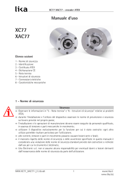
XC77 XAC77 encoder ATEX Manuale d’uso XC77 XAC77 Elenco sezioni 1 2 3 4 5 6 7 8 Norme di sicurezza Identificazione Certificato ATEX Dichiarazione CE Nota tecnica Istruzioni di sicurezza Connessioni elettriche Caratteristiche meccaniche 1 Norme di sicurezza Sicurezza • osservare la “Nota tecnica” e le “Istruzioni di sicurezza” relative ai prodotti ATEX. • osservare le norme di prevenzione e sicurezza sul lavoro durante l’installazione e l’utilizzo del dispositivo previste nel proprio paese; • l’installazione deve essere eseguita solo da personale qualificato, in assenza di tensione e movimento d'albero; • utilizzare il dispositivo esclusivamente per la funzione per cui è stato costruito; • alte correnti, tensioni e parti in rotazione possono causare lesioni serie o fatali. Avvertenze elettriche • effettuare le connessioni elettriche esclusivamente in assenza di tensione; • rispettare le connessioni riportate nel capitolo “Connessioni elettriche”; • in riferimento alla normativa 89/336/CEE sulla compatibilità elettromagnetica rispettare le seguenti precauzioni: 8 prima di maneggiare e installare il dispositivo eliminare la presenza di carica elettrostatica dal proprio corpo e dagli utensili che andranno a contatto con il dispositivo; 8 alimentare il dispositivo con tensione stabilizzata e priva di disturbi, se necessario, installare appositi filtri EMC all’ingresso dell’alimentazione; 8 utilizzare sempre cavi schermati e possibilmente “twistati”; 8 non usare cavi più lunghi del necessario; 8 evitare di far passare il cavo dei segnali del dispositivo vicino a cavi di potenza; 8 installare il dispositivo il più lontano possibile da possibili fonti di interferenza o schermarlo in maniera efficace; 8 collegare la calza del cavo o la custodia del connettore ad un buon punto di terra; assicurarsi che il punto di terra sia privo di disturbi. Il collegamento a terra può essere effettuato nel lato encoder e/o nel lato utilizzatore, è compito dell’utilizzatore valutare la soluzione migliore da adottare per minimizzare i disturbi. Avvertenze meccaniche • encoder con albero sporgente: utilizzare giunti elastici per congiungere encoder e motore, rispettare le tolleranze di allineamento ammesse dal giunto elastico; • non disassemblare il dispositivo; • non eseguire lavorazioni meccaniche sul dispositivo; • evitare urti o forti sollecitazioni sia all’albero che al corpo del dispositivo; • utilizzare il dispositivo in accordo con le caratteristiche ambientali dello stesso. MAN XC77_XAC77 I_E 1.4.doc Pag.1 PH SYSTEMS - www.phsystems.be - [email protected] www.lika.it www.lika.biz XC77 XAC77 encoder ATEX 2 Identificazione Il dispositivo si identifica dal codice e dal numero di serie stampati sull'etichetta e attraverso i documenti di trasporto dello stesso. Per dettagli relativi alle caratteristiche elettriche fare riferimento al catalogo del prodotto. 3 Certificato ATEX MAN XC77_XAC77 I_E 1.4.doc Pag.2 PH SYSTEMS - www.phsystems.be - [email protected] www.lika.it www.lika.biz XC77 XAC77 encoder ATEX MAN XC77_XAC77 I_E 1.4.doc Pag.3 PH SYSTEMS - www.phsystems.be - [email protected] www.lika.it www.lika.biz XC77 XAC77 encoder ATEX MAN XC77_XAC77 I_E 1.4.doc Pag.4 PH SYSTEMS - www.phsystems.be - [email protected] www.lika.it www.lika.biz XC77 XAC77 encoder ATEX 4 Dichiarazione CE MAN XC77_XAC77 I_E 1.4.doc Pag.5 PH SYSTEMS - www.phsystems.be - [email protected] www.lika.it www.lika.biz XC77 XAC77 encoder ATEX 5 Nota tecnica MAN XC77_XAC77 I_E 1.4.doc Pag.6 PH SYSTEMS - www.phsystems.be - [email protected] www.lika.it www.lika.biz XC77 XAC77 encoder ATEX 6 Istruzioni di sicurezza MAN XC77_XAC77 I_E 1.4.doc Pag.7 PH SYSTEMS - www.phsystems.be - [email protected] www.lika.it www.lika.biz XC77 XAC77 encoder ATEX MAN XC77_XAC77 I_E 1.4.doc Pag.8 PH SYSTEMS - www.phsystems.be - [email protected] www.lika.it www.lika.biz XC77 XAC77 encoder ATEX 7 Connessioni elettriche ATTENZIONE: Collegare la calza del cavo o la custodia del connettore ad un buon punto di terra; assicurarsi che il punto di terra sia privo di disturbi. Si consiglia di effettuare il collegamento a terra il più vicino possibile all’encoder. 7.1 XC77…ZCU… Cavo 8 poli Giallo Blu Verde Arancio Bianco Grigio Rosso Nero Calza Funzione A /A B /B 0 /0 +Vdc 0Vdc GND Schermatura 7.2 XAC77 con interfaccia SSI Cavo 8 poli Bianco Marrone Verde Giallo Rosa Blu Rosso Nero Calza MAN XC77_XAC77 I_E 1.4.doc Funzione Clock + Clock 8 Data + Data 8 Azzeramento Complementario +10Vdc +30Vdc 0Vdc GND Schermatura Pag.9 PH SYSTEMS - www.phsystems.be - [email protected] www.lika.it www.lika.biz XC77 XAC77 encoder ATEX 7.3 XAC77 con uscita parallela (NPN o.c. / PushPull ) Cavo 16 poli Marrone Rosso Rosa Giallo Verde Blu Viola Grigio Bianco Nero Bianco8Verde Marrone8Verde 8 8 8 8 8 8 8 8 8 8 8 8 8 Rosso8Blu Grigio8Rosa Bianco8Giallo Giallo8Marrone Calza MAN XC77_XAC77 I_E 1.4.doc Cavo 19 poli Marrone Rosso Rosa Giallo Verde Blu Viola Grigio Bianco Nero Bianco8Verde Marrone8Verde Rosso8Blu Grigio8Marrone Bianco8Grigio 8 8 8 8 8 8 8 8 8 8 Bianco8Rosa Grigio8Rosa Bianco8Giallo Giallo8Marrone Calza Cavo 32 poli Marrone Rosso Rosa Giallo Verde Blu Viola Grigio Bianco Nero Marrone8Rosso Bianco8Rosso Rosso8Blu Grigio8Rosa Bianco8Giallo Marrone8Verde Bianco8Verde Giallo8Marrone Bianco8Blu Marrone8Blu Bianco8Rosa Bianco8Grigio Rosa8Marrone Grigio8Marrone Marrone8Nero Grigio8Verde Giallo8Rosa Verde8Blu Giallo8Blu Calza Funzione 1 LSB 2 3 4 5 6 7 8 9 10 11 12 13 14 15 16 17 18 19 20 21 22 23 24 25 Azzeramento Complementario +10Vdc +30Vdc 0Vdc GND Schermatura Pag.10 PH SYSTEMS - www.phsystems.be - [email protected] www.lika.it www.lika.biz XC77 XAC77 encoder ATEX 7.4 XAC77 con interfaccia Profibus (XAC7716/16384PB14) Gli encoder Profibus ATEX rispecchiano le caratteristiche di comunicazione degli encoder serie Hx58 FB, il file GSD HM58_V3.gsd e il manuale relativo all’interfaccia Profibus sono nel supporto allegato oppure all’indirizzo internet www.lika.it > PRODOTTI > ROTACOD > Hx58 FB). Cavo Profibus Blu Nero Verde Rosso Giallo_Verde Calza Funzione +10Vdc +30Vdc Alimentazione 0Vdc GND Alimentazione Profibus A Profibus B non connesso Profibus Shield ATTENZIONE: • l’indirizzo nodo deve essere impostato via software dal Master (vedi servizio SAP55: Cambio numero nodo via BUS nel manuale d’uso Profibus). Il Baud rate è settato automaticamente dal Master. Non è consentito aprire l’encoder! • se l’encoder è l’ultimo dispositivo della rete, la resistenza di terminazione va montata esternamente al dispositivo (terminale di rete da 120Ω tra Profibus A e Profibus B). • i LED di diagnostica non sono presenti su questo modello. 7.5 XAC77 con interfaccia CANopen (XAC7716/16384CB14) Gli encoder CANopen ATEX rispecchiano le caratteristiche di comunicazione degli encoder serie Hx58 FB, il file EDS Lika_HMCB_DS406_V3.eds e il manuale relativo all’interfaccia CANopen sono nel supporto allegato oppure all’indirizzo internet www.lika.it > PRODOTTI > ROTACOD > Hx58 FB). Cavo CAN Rosso Nero Bianco Blu Calza Funzione +10Vdc +30Vdc Alimentazione 0Vdc GND Alimentazione CAN High CAN Low CAN Shield ATTENZIONE: • l’indirizzo nodo e il baud rate devono essere impostati via software dal Master (vedi parametri 3000h e 3001h del dizionario oggetti). Non è consentito aprire l’encoder! • se l’encoder è l’ultimo dispositivo della rete, la resistenza di terminazione va montata esternamente al dispositivo (terminale di rete da 120Ω tra CAN High e CAN Low). • i LED di diagnostica non sono presenti su questo modello. MAN XC77_XAC77 I_E 1.4.doc Pag.11 PH SYSTEMS - www.phsystems.be - [email protected] www.lika.it www.lika.biz XC77 XAC77 encoder ATEX 7.6 XAC77 con uscita analogica (XAC77…AI1…) Cavo 8 poli Marrone Bianco Verde Blu Giallo Rosso Nero Funzione +Iout (4820mA) 8Iout (4820mA) Complementario Fault Hold +15Vdc +30Vdc 0Vdc GND Descrizione: • Uscita AI1: Posiz. 0 = 4 mA, Posiz. max = 20 mA • Uscita “lout” è internamente collegato a GND • Hold = Ingresso di Latch dati (attivo alto da +10V a +30V) • Fault = Segnale di errore ad es. interruzione cavo. Per il collegamento seguire le figure 2 e 3, prestare attenzione al valore di R2. Nessun errore = transistor ON (in conduzione). Errore encoder = transistor OFF (aperto). • Incremento ad ogni passo: Modello 420 mA XAC77 12 3,9 µA XAC77 12/16 0,24 µA XAC77 09/64 0,48 µA XAC77 06/256 0,97 µA Fault connesso ad un ingresso del PLC: Fault connesso ad un relè: Imax = 50mA Vdc R2 = − R1 R1 = 47Ω I fig.2 fig.3 Esempio: 1KΩ < R2 < 10KΩ Nessun errore = PLC input basso (0Vdc). Errore encoder = PLC input alto (+Vdc). Esempio: Vdc = +24V I = 30mA (corrente necessaria per eccitare la bobina di un piccolo relè) R2 = 750Ω Nessun errore = bobina eccitata. Errore encoder = bobina a riposo. MAN XC77_XAC77 I_E 1.4.doc Pag.12 PH SYSTEMS - www.phsystems.be - [email protected] www.lika.it www.lika.biz XC77 XAC77 encoder ATEX 8 Caratteristiche meccaniche 8.1 XC77 8.2 XAC77 MAN XC77_XAC77 I_E 1.4.doc Pag.13 PH SYSTEMS - www.phsystems.be - [email protected] www.lika.it www.lika.biz XC77 XAC77 encoder ATEX 8.3 Albero sporgente (LKM1758) e molla di sostegno (LKM1520) LKM81758 è un accessorio che deve essere ordinato separatamente. MAN XC77_XAC77 I_E 1.4.doc Pag.14 PH SYSTEMS - www.phsystems.be - [email protected] www.lika.it www.lika.biz XC77 XAC77 encoder ATEX MAN XC77_XAC77 I_E 1.4.doc Pag.15 PH SYSTEMS - www.phsystems.be - [email protected] www.lika.it www.lika.biz XC77 XAC77 encoder ATEX Vers. man. 1.0 1.1 1.2 1.4 Descrizione Prima stampa Aggiunto capitolo 7.6 Aggiunti capitoli 7.7 e 7.8 Aggiornato capitolo 7 LIKA Electronic Via S. Lorenzo, 25 8 36010 Carrè (VI) 8 Italy Tel. +39 0445 382814 Fax +39 0445 382797 Italy: eMail [email protected] 8 www.lika.it World: eMail [email protected] 8 www.lika.biz MAN XC77_XAC77 I_E 1.4.doc Pag.16 PH SYSTEMS - www.phsystems.be - [email protected] www.lika.it www.lika.biz XC77 XAC77 encoder ATEX User manual XC77 XAC77 Chapters 1 2 3 4 5 6 7 8 Safety summary Identification ATEX certificate CE declaration of conformity Technical notes Safety instructions Electrical connections Mechanical 1 Safety summary Safety • observe “Technical notes” and “Safety instructions” relating to ATEX products; • observe the professional safety and accident prevention regulations applicable to your country during device installation and operation; • installation has to be carried out by qualified personnel only, without power supply and stationary shaft; • the encoder must be used only for the purpose appropriate to its design; • high current, voltage and rotating parts can cause serious or fatal injury. Electrical safety • switch OFF the voltage before connecting the device; • connect according to the chapter “Electrical connections”; • according to the 89/336/CEE norm on electromagnetic compatibility, following precautions must be taken: 8 before handling and installing, discharge electrical charge from your body and tools which may come in touch with the device; 8 power supply must be stable without noise, install EMC filters on device power supply if needed; 8 always use shielded and twisted cables if possible; 8 avoid cables runs longer than necessary; 8 avoid running the signal cable near high voltage power cables; 8 mount the device as far as possible from any capacitive or inductive noise source, shield the device from noise source if needed; 8 minimize noise by connecting shield or connector housing to ground (GND). Make sure that ground (GND) is not affected by noise. The shield connection point to ground can be situated both on the device side and on user’s side. The best solution to minimize the interference must be carried out by the user. Mechanical safety • solid shaft: use a flexible coupling to connect encoder to motor shaft respecting the coupling misalignment tolerances; • do not disassemble the encoder; • do not tool the encoder or its shaft; • do not subject the encoder and the shaft to knocks or shocks; • respect the environmental characteristics of the product. MAN XC77_XAC77 I_E 1.4.doc Pag.17 PH SYSTEMS - www.phsystems.be - [email protected] www.lika.it www.lika.biz XC77 XAC77 encoder ATEX 2 Identification The device can be identified by the label's data (ordering code, serial number). This information is listed in the delivery document. For technical features of the product, refer to the technical catalogue. 3 ATEX certificate MAN XC77_XAC77 I_E 1.4.doc Pag.18 PH SYSTEMS - www.phsystems.be - [email protected] www.lika.it www.lika.biz XC77 XAC77 encoder ATEX MAN XC77_XAC77 I_E 1.4.doc Pag.19 PH SYSTEMS - www.phsystems.be - [email protected] www.lika.it www.lika.biz XC77 XAC77 encoder ATEX MAN XC77_XAC77 I_E 1.4.doc Pag.20 PH SYSTEMS - www.phsystems.be - [email protected] www.lika.it www.lika.biz XC77 XAC77 encoder ATEX 4 CE declaration of conformity MAN XC77_XAC77 I_E 1.4.doc Pag.21 PH SYSTEMS - www.phsystems.be - [email protected] www.lika.it www.lika.biz XC77 XAC77 encoder ATEX 5 Technical notes MAN XC77_XAC77 I_E 1.4.doc Pag.22 PH SYSTEMS - www.phsystems.be - [email protected] www.lika.it www.lika.biz XC77 XAC77 encoder ATEX 6 Safety instructions MAN XC77_XAC77 I_E 1.4.doc Pag.23 PH SYSTEMS - www.phsystems.be - [email protected] www.lika.it www.lika.biz XC77 XAC77 encoder ATEX MAN XC77_XAC77 I_E 1.4.doc Pag.24 PH SYSTEMS - www.phsystems.be - [email protected] www.lika.it www.lika.biz XC77 XAC77 encoder ATEX 7 Electrical connections ATTENTION: minimize noise by connecting shield or connector housing to ground (GND). Make sure that ground (GND) is not affected by noise. It’s recommended to provide the ground connection as close as possible to the encoder. 7.1 XC77…ZCU… Cable 8 wires Yellow Blue Green Orange White Grey Red Black Screen Function A /A B /B 0 /0 +Vdc 0Vdc GND Shield 7.2 XAC77 with SSI interface Cable 8 wires White Brown Green Yellow Pink Blue Red Black Screen MAN XC77_XAC77 I_E 1.4.doc Function Clock + Clock 8 Data + Data 8 Zero setting Complementary (counting direction) +10Vdc +30Vdc 0Vdc GND Shield Pag.25 PH SYSTEMS - www.phsystems.be - [email protected] www.lika.it www.lika.biz XC77 XAC77 encoder ATEX 7.3 XAC77 with bit parallel output (NPN o.c. / PushPull ) Cable 16 wires Brown Red Pink Yellow Green Blue Violet Grey White Black White8Green Brown8Green 8 8 8 8 8 8 8 8 8 8 8 8 8 Red8Blue Grey8Pink White8Yellow Yellow8Brown Screen MAN XC77_XAC77 I_E 1.4.doc Cable 19 wires Brown Red Pink Yellow Green Blue Violet Grey White Black White8Green Brown8Green Red8Blue Grey8Brown White8Grey 8 8 8 8 8 8 8 8 8 8 White8Pink Grey8Pink White8Yellow Yellow8Brown Screen Cable 32 wires Brown Red Pink Yellow Green Blue Violet Grey White Black Brown8Red White8Red Red8Blue Grey8Pink White8Yellow Brown8Green White8Green Yellow8Brown White8Blue Brown8Blue White8Pink White8Grey Pink8Brown Grey8Brown Brown8Black Grey8Green Yellow8Pink Green8Blue Yellow8Blue Screen Function 1 LSB 2 3 4 5 6 7 8 9 10 11 12 13 14 15 16 17 18 19 20 21 22 23 24 25 Zero setting Complementary +10Vdc +30Vdc 0Vdc GND Shield Pag.26 PH SYSTEMS - www.phsystems.be - [email protected] www.lika.it www.lika.biz XC77 XAC77 encoder ATEX 7.4 XAC77 with ProfibusDP interface (XAC7716/16384PB14) ATEX encoders with Profibus interface are based on the Hx58 FB series, thus follow all specifications of transmission described in the HM58 Profibus manual and need the GSD file HM58_V3.gsd. Manual and GSD file are available on the supplied CD or our web site at: www.lika.biz > PRODUCTS > ROTACOD > Hx58 FB). Profibus Cable Blue Black Green Red Yellow_Green Shield Function +10Vdc +30Vdc Supply voltage 0Vdc GND Supply voltage Profibus A Profibus B not connected Profibus Shield ATTENTION: • the node number must be set via software SAP55 service (see “Set node number via BUS” on Profibus user manual). Baud rate is set automatically by the bus Master. Do not open the device for any setting! • if the encoder is the last device of network, the bus termination resistance must be mounted externally to the device (bus termination resistance of 120Ω between Profibus A and Profibus B); • the diagnostic LEDs are not present on this model of encoder. 7.5 XAC77 with CANopen interface (XAC7716/16384CB14) ATEX encoders with CANopen interface are based on the Hx58 FB series, thus follow all specifications of transmission described in the HM58 CANopen manual and need the EDS file Lika_HMCB_DS406_V3.eds. Manual and EDS file are available on the supplied CD or our web site at: www.lika.biz > PRODUCTS > ROTACOD > Hx58 FB). CAN Cable Red Black White Blue Shield Function +10Vdc +30Vdc Supply voltage 0Vdc GND Supply voltage CAN High CAN Low CAN Shield ATTENTION: • the node number and the baud rate must be set via software by the bus Master (see objects 3000h e 3001h of Object dictionary). Do not open the device for any setting! • if the encoder is the last device of network, the bus termination resistance must be mounted externally to the device (bus termination resistance of 120Ω between CAN High and CAN Low); • the diagnostic LEDs are not present on this model of encoder. MAN XC77_XAC77 I_E 1.4.doc Pag.27 PH SYSTEMS - www.phsystems.be - [email protected] www.lika.it www.lika.biz XC77 XAC77 encoder ATEX 7.6 XAC77 with analog output (XAC77…AI1…) Cable 8 wires Brown White Green Blue Yellow Red Black Function +Iout (4820mA) 8Iout (4820mA) Complementary Fault Hold +15Vdc +30Vdc 0Vdc GND Description: • Output AI1: Quote 0 = 4mA, Max quote = 20mA • ”lout“ signal is internally connected to GND • Hold = Data latch in memory (active high +10V +30V) • Fault = Open collector signal for cable integrity check. To connect fault signal, follow fig.2 and fig.3, pay attention to the value of R2. No enc. error = transistor ON (in conduction). Encoder error = transistor OFF (open). • Increment each step: Type 420 mA XAC77 12 3,9 µA XAC77 12/16 0,24 µA XAC77 09/64 0,48 µA XAC77 06/256 0,97 µA Fault connected to PLC input: Fault connected to relay: Imax = 50mA Vdc R1 = 47Ω R2 = − R1 I fig.2 fig.3 Example: 1KΩ < R2 < 10KΩ No enc. error = PLC input Low (0 Vdc). Encoder error = PLC input High (+Vdc). MAN XC77_XAC77 I_E 1.4.doc Example: Vdc = +24V I = 30mA (current necessary to energize the coil of a small relay) R2 = 750Ω No enc. error = coil energized. Encoder error = coil not energized. Pag.28 PH SYSTEMS - www.phsystems.be - [email protected] www.lika.it www.lika.biz XC77 XAC77 encoder ATEX 8 Mechanical 8.1 XC77 8.2 XAC77 MAN XC77_XAC77 I_E 1.4.doc Pag.29 PH SYSTEMS - www.phsystems.be - [email protected] www.lika.it www.lika.biz XC77 XAC77 encoder ATEX 8.3 Solid shaft (LKM1758) and Fixing plate (LKM1520) LKM81758 is an accessory to be ordered separately. MAN XC77_XAC77 I_E 1.4.doc Pag.30 PH SYSTEMS - www.phsystems.be - [email protected] www.lika.it www.lika.biz XC77 XAC77 encoder ATEX MAN XC77_XAC77 I_E 1.4.doc Pag.31 PH SYSTEMS - www.phsystems.be - [email protected] www.lika.it www.lika.biz XC77 XAC77 encoder ATEX Vers. man. 1.0 1.1 1.2 1.4 Description 1st issue Add chapter 7.6 Add chapters 7.7 and 7.8 Chapter 7 update LIKA Electronic Via S. Lorenzo, 25 8 36010 Carrè (VI) 8 Italy Tel. +39 0445 382814 Fax +39 0445 382797 Italy: eMail [email protected] 8 www.lika.it World: eMail [email protected] 8 www.lika.biz MAN XC77_XAC77 I_E 1.4.doc Pag.32 PH SYSTEMS - www.phsystems.be - [email protected] www.lika.it www.lika.biz
Scaricare