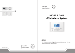
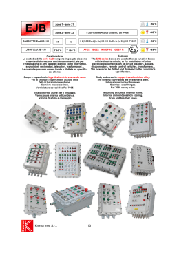
SERVICE MANUAL DISHWASHERS ELECTROLUX ITALIA S.p.A. Spares Operations Europe Corso Lino Zanussi, 30 I - 33080 PORCIA/PN (ITALY) Fax +39 0434 394096 Dishwashers with electronic control system Publication number 599 72 48-93 EN ProClean RealLife Edition: 2011/01 SOE/PR 1 599 72 48-93 CONTENTS 1 2 3 3.1 3.2 3.3 4 4.1 4.2 4.3 5 6 6.1 6.2 Purpose of this manual.............................................................................................................................4 Precautions...............................................................................................................................................4 Styling overview........................................................................................................................................5 Free Standing ....................................................................................................................................... 5 Fully Integrated ..................................................................................................................................... 6 Built In................................................................................................................................................... 7 Location of LEDs and Push Buttons ......................................................................................................10 EDW1xxx-2G display boards.............................................................................................................. 10 EDW3000 display boards ................................................................................................................... 10 “New Collection” display boards ......................................................................................................... 10 Reset ......................................................................................................................................................11 User Mode Settings................................................................................................................................12 Entering the User Mode...................................................................................................................... 12 Water hardness .................................................................................................................................. 13 6.2.1 6.2.2 6.2.3 6.2.4 6.2.5 6.3 6.4 Disable/Enable Rinse Aid ................................................................................................................... 15 Disable/Enable Buzzer ....................................................................................................................... 15 6.4.1 7 EDW500 .................................................................................................................................................... 13 EDW503 .................................................................................................................................................... 13 EDW750 .................................................................................................................................................... 14 EDW1850/1950 ......................................................................................................................................... 14 EDW1953 TOUCH .................................................................................................................................... 14 EDW503 .................................................................................................................................................... 15 Service Mode Settings ...........................................................................................................................16 7.1 EDW500 ............................................................................................................................................. 16 7.1.1 7.1.2 7.1.3 7.1.4 7.2 EDW503 ............................................................................................................................................. 18 7.2.1 7.2.2 7.2.3 7.2.4 7.3 7.4 7.5 7.6 7.7 7.8 Diagnostics mode, alarm reading and testing............................................................................................ 16 Deleting alarm memory/LED test............................................................................................................... 17 Functional test cycle.................................................................................................................................. 17 Quitting diagnostics mode ......................................................................................................................... 17 Diagnostics mode, alarm reading and testing............................................................................................ 18 Deleting alarm memory/LED test............................................................................................................... 18 Functional test cycle.................................................................................................................................. 19 Reading alarms and activating components.............................................................................................. 19 EDW750 ............................................................................................................................................. 20 EDW1850 ........................................................................................................................................... 20 EDW1950/1953 .................................................................................................................................. 20 EDW3510 ........................................................................................................................................... 21 EDW2500 SWISS............................................................................................................................... 22 EDW1850/1950 .................................................................................................................................. 23 7.8.1 LED test and cancelling alarms stored ...................................................................................................... 23 7.9 EDW1850/1950 .................................................................................................................................. 23 7.10 Test programme ............................................................................................................................. 23 7.11 EDW1850/1950 .............................................................................................................................. 24 7.12 Enable/Disable additional rinse...................................................................................................... 24 7.13 EDW750 ......................................................................................................................................... 25 7.14 EDW1850/1950 .............................................................................................................................. 25 7.15 EDW1953 TOUCH ......................................................................................................................... 25 8 Service Mode Settings for EDW2510 “Touch” .......................................................................................26 8.1 Accessing diagnostics mode .............................................................................................................. 26 8.2 Alarms and activating individual components .................................................................................... 27 9 Alarm codes............................................................................................................................................29 9.1 Alarm Management ............................................................................................................................ 29 9.2 Description of the alarms.................................................................................................................... 30 9.2.1 9.2.2 9.2.3 9.2.4 9.2.5 9.2.6 9.2.7 9.2.8 9.2.9 9.2.10 9.2.11 9.2.12 SOE/PR “i00” code family: Low mains voltage ........................................................................................................ 30 “i10” code family: Water tap closed ........................................................................................................... 30 “i20” code family: Draining problems ......................................................................................................... 30 “i30” code family: Aqua Control ................................................................................................................. 30 “i40” code family: analogue pressure switch.............................................................................................. 31 “i50” code family: Washing motor problems .............................................................................................. 31 “i60” code family: Heating element problems ............................................................................................ 32 “i70” code family: NTC problems ............................................................................................................... 32 “i90” code family: Configuration problems ................................................................................................. 32 “iB0” code family: Turbidity Sensor Problems............................................................................................ 32 “iC0” code family: Communication problems ............................................................................................. 32 “iD0” code family: Tacho problems............................................................................................................ 33 2 599 72 48-93 9.2.13 9.2.14 “iE0” code family: Flowmeter position........................................................................................................ 33 “iF0” code family: Over-filling..................................................................................................................... 33 10 Technical details.....................................................................................................................................34 10.1 New hydraulic circuit ...................................................................................................................... 34 10.2 New components............................................................................................................................ 36 10.3 Water circuit ................................................................................................................................... 38 10.4 Single-phase asynchronous washing pump .................................................................................. 39 10.5 Three-phase washing pump - inverter motor ................................................................................. 40 10.6 Drain pump..................................................................................................................................... 42 10.7 Heating element ............................................................................................................................. 43 10.8 Analogue pressure switch .............................................................................................................. 44 10.9 Flowmeter....................................................................................................................................... 45 10.10 Detergent dispenser ....................................................................................................................... 48 10.11 Traditional door .............................................................................................................................. 49 10.12 ON/OFF Switch .............................................................................................................................. 50 10.13 Beam-on-Floor ............................................................................................................................... 53 10.14 EDW1xxx-2G operating diagram ................................................................................................... 54 10.15 EDW3000 operating diagram (single-phase motor)....................................................................... 55 10.16 EDW3000 operating diagram (three-phase Inverter motor)........................................................... 56 10.17 Components check for AC motor ................................................................................................... 57 SOE/PR 3 599 72 48-93 1 Purpose of this manual The purpose of this Service Manual is to provide Service Engineers with technical information regarding the new range of “ProClean/RealLife” dishwashers and to give a description of the alarm codes and service functionality of the following families: • EDW5xx • EDW750 • EDW1xxx-2G • EDW2500 • EDW3000 • EDW3510 This Manual describes: • General characteristics • Control panel and programmes • Technical characteristics • Guide to diagnostics For more detailed information regarding the hydraulic circuits and the structural characteristics of the appliances, please refer to the Service Manual for the “ProClean/RealLife” structure. 2 Precautions Electrical appliances must be serviced only by qualified Service Engineers. Always remove the plug from the power socket before touching internal components. REVISIONS: Revision Date 00 12/2009 Document creation 01 07/2010 Added Service Mode Settings for EDW2510 “Touch” 02 10/2010 Alarm i00 added 03 01/2011 Stylings updated and “Service Mode” variants added SOE/PR Description 4 599 72 48-93 3 Styling overview 3.1 Free Standing EDW2500 EDW1510-1750 EDW1500 EDW750 EDW1850 EDW1950 EDW3510 SOE/PR 5 599 72 48-93 3.2 Fully Integrated EDW1953 EDW1103 SOE/PR 6 599 72 48-93 3.3 Built In SOE/PR 7 599 72 48-93 EDW750 EDW1850 EDW1950 EDW3510 EDW2500 SWISS SOE/PR 8 599 72 48-93 EDW 500 EDW 503 EDW 1503 SOE/PR 9 599 72 48-93 4 Location of LEDs and Push Buttons 4.1 EDW1xxx-2G display boards EDW 1500-2G-UI: EDW 1510-2G-UI (also used as EDW 1750-2G-UI) EDW 1503-2G-UI (also used as EDW1753-2G-UI): EDW 1103-2G-UI (also used as EDW603 user interface): 4.2 EDW3000 display boards 4.3 “New Collection” display boards EDW750 EDW1850 EDW1950 TOUCH EDW3510 EDW500 SOE/PR EDW1953 FI EDW 503 EDW1503 1.5 DIGIT 10 599 72 48-93 5 Reset “Reset” is a special kind of User mode to stop or deselect a running programme. When this function is enabled, the appliance will be on stand-by without any selected settings. RESET can only be performed after the washing cycle has started. With EDW1xxx-2G display boards: press buttons S2+S3 simultaneously for at least 1 sec or press the specific button dedicated to this function by the custom software. With EDW3000 display boards: press buttons S3+S4 simultaneously for at least 1 sec or press the specific button dedicated to this function by the custom software. 1 2 3 4 With display boards from the “New Collection”: press buttons S1+S2 or S3+S4 simultaneously for at least 1 sec or press the specific button dedicated to this function by the custom software. SOE/PR 11 599 72 48-93 6 User Mode Settings 6.1 Entering the User Mode You can enter this Mode by pressing the two configured buttons simultaneously for at least 2 sec after the appliance has been turned on and is on stand-by without any selected programme: with EDW1xxx-2G display boards: by pressing buttons S2+S3. with EDW3xxx display boards: from the options menu. You can quit User Mode by turning off the appliance or after a 60 sec timeout. When this mode is enabled, it is indicated by the flashing of the LEDs corresponding to the buttons available in this mode. The User mode is incorporated into the options menu on the displays. Example for a 3-digit display: 1. 2. For the EDW750, set the knob to a position without a washing cycle indication, as shown in the figure, and press buttons S1+S2 simultaneously for a few seconds. For the EDW1850-1950, you can enable it by pressing the two configured buttons simultaneously for at least 2 sec after the appliance has been turned on and is on stand-by without any selected programme: For the EDW1953 TOUCH, you can enable it by pressing the two configured buttons simultaneously for at least 2 sec after the appliance has been turned on and is on stand-by without any selected programme: SOE/PR 12 599 72 48-93 6.2 Water hardness The water hardness setting range is from 1 to 10 (soft to hard). In appliances with a 3-digit display, once you have entered the User mode, press button S1 to display the current water hardness level from “1L” to “10L”. In appliances without a display, once you have entered the User mode, press button S1 to display the current water hardness level from “1L” to “10L" with the flashing of the cycle end LED. Press button S1 to increase the hardness setting by one. The new level is displayed accordingly. To store the new setting, press button S0. 6.2.1 1. 2. ª ª EDW500 Hold down button S1 Turn the knob clockwise to Position 1 LEDs LD0 and LD1 flash release button S1 3. Press button S1 ª the level of regenerating is displayed through a series of flashes, interrupted by pauses, emitted by the Cycle end LED 4. Press button S1 again to increase the regenerating level 6.2.2 EDW503 Hold down the programmes button. LED L1 flashes and L2 is turned on permanently. Release the button. LED L1 flashes, LED L2 is turned off and the CYCLE END LED flashes to indicate the regenerating level set. To modify the regenerating level, press the programmes button. The CYCLE END LED will flash to indicate the new level set. SOE/PR 13 599 72 48-93 6.2.3 EDW750 6.2.4 EDW1850/1950 6.2.5 EDW1953 TOUCH SOE/PR 14 599 72 48-93 6.3 Disable/Enable Rinse Aid This function allows you to disable the rinse aid dosing. In appliances with a 3-digit display, once you have entered the User mode, press button S2 to display the current status where “0d” indicates it is disabled and “1d” that it is enabled. To modify the enabled/disabled status, press button S2. The new setting is then displayed. 6.4 Disable/Enable Buzzer This function allows you to disable the cycle end buzzer. In appliances with a 3-digit display, once you have entered the User mode, press button S3 to display the current status where “0b” indicates it is disabled and “1b” that it is enabled. To modify the enabled/disabled status, press button S3. The new setting is then displayed. 6.4.1 EDW503 Hold down the programmes button LED L1 flashes and L2 is turned on permanently Release the button and press it again: LED L1 is lit permanently and L2 flashes After a few seconds, LED L1 is turned off and L2 flashes; the CYCLE END LED will indicate whether the buzzer is enabled. To enable or disable the BUZZER, press the programmes button (cycle end on = buzzer enabled). SOE/PR 15 599 72 48-93 7 Service Mode Settings Only if the appliance is on stand-by awaiting instructions, hold down the two configured buttons simultaneously, turn on the appliance and wait for at least 4 sec. With EDW1xxx-2G display boards: by pressing buttons S1+S3. With EDW3xxx display boards: by pressing buttons S1+S3 (EDW2500) or S3+S4 (EDW2503). 7.1 7.1.1 1. 2. ª ª EDW500 Diagnostics mode, alarm reading and testing Hold down button S1 Turn the knob anti-clockwise to Position 5 LEDs LD0 and LD1 flash release button S1 3. Press button S1 ª the first alarm stored is displayed: the Cycle end LED flashes in sequence, interrupted by pauses, corresponding to the alarm: for the alarm code, please see the alarms summary table. 4. Press button S1 again to display the second alarm 5. Press button S1 once more to display the third alarm 6. Press button S1 for the fourth time to move on to enabling the appliance's actuators, the CYCLE END LED is on: ª 4th activation: regenerating solenoid valve ª 5th activation: drain pump ª 6th activation: water fill to level solenoid valve ª 7th activation: heating (only if the level of water is reached) ª 8th activation: washing pump ª 9th activation: detergent/rinse aid dispenser ª 10th activation: drying fan (if turbo-dry) 7. All the positions can be repeated by pressing button S1 in sequence The components are powered if the appliance door is shut: open the door to select another actuator then shut it again. If button S1 is not pressed for 60 seconds, you automatically quit diagnostics mode. SOE/PR 16 599 72 48-93 7.1.2 1. 2. ª ª Deleting alarm memory/LED test Hold down button S1 Turn the knob anti-clockwise to Position 5 LEDs LD0 and LD1 flash release button S1 3. Turn the knob to Position 4 4. Press button S1 ª all LEDS flash for 30 sec 7.1.3 Functional test cycle 7.1.3.1 1. 2. ª ª Cycle setting Hold down button S1 Turn the knob anti-clockwise to Position 5 LEDs LD0 and LD1 flash release button S1 3. Turn the knob to Position 3 ª press button S1 ª the cycle starts: during its progress, the programme behaves like a normal cycle ª LED LD1 flashes N.B.: at the beginning of the next programme after the test cycle, the resins are washed. The overall duration of the cycle is approximately 50 minutes. 7.1.4 Quitting diagnostics mode To quit diagnostics mode, press button S0 and turn off the appliance or wait 60 seconds: the LEDS are turned on and the appliance is on stand-by awaiting your selection SOE/PR 17 599 72 48-93 7.2 7.2.1 EDW503 Diagnostics mode, alarm reading and testing 1. Hold down the PROGRAMMES button 2. Turn the appliance on at the ON/OFF button ª LED L1 flashes ª LEDs L2 and L3 are turned on 3. Wait for LEDs L2 and L3 to be turned off 4. Press the PROGRAMMES button ª the CYCLE END LED shows the first alarm stored with a sequence of flashes 5. Press the PROGRAMMES button twice more to display the other two alarms stored ª the CYCLE END LED shows the alarms 6. From the 4th activation, the individual components testing begins according to the defined sequence ª LED L2 is turned on permanently for the duration of the components test ª 4th activation: regenerating solenoid valve ª 5th activation: drain pump ª 6th activation: water fill to level solenoid valve (level of water reached) ª 7th activation: heating (only if the level of water is reached) ª 8th activation: washing pump ª 9th activation: detergent/rinse aid dispenser ª 10th activation: drying fan ª 11th activation: the cycle is repeated from the first alarm All the positions can be repeated by pressing button S2 in sequence. The components are powered with the appliance door open and shut. If the PROGRAMMES button is not pressed for 60 seconds, you automatically quit diagnostics mode. 7.2.2 Deleting alarm memory/LED test 1. Hold down the PROGRAMMES button 2. Turn the appliance on at the ON/OFF button ª LED L1 flashes ª LEDs L2 and L3 are turned on 3. Press the PROGRAMMES button before LEDs L2 and L3 are turned off ª LED L2 flashes ª LEDs L1 and L3 are turned on 4. Wait for LEDs L1 and L3 to be turned off 5. Press the PROGRAMMES button ª all LEDs flash and the buzzer sounds SOE/PR 18 599 72 48-93 7.2.3 Functional test cycle 7.2.3.1 Cycle setting 1. Hold down the PROGRAMMES button 2. Turn the appliance on at the ON/OFF button ª LED L1 flashes ª LEDs L2 and L3 are turned on 4. Press the PROGRAMMES button twice before LEDs L2 and L3 are turned off ª LED L3 flashes ª LEDs L1 and L2 are turned on 5. Wait for LEDs L1 and L2 to be turned off 6. Press the PROGRAMMES button to start the test cycle ª LED L4 is turned off ª LED L2 flashes for the duration of the cycle 7.2.3.2 Cycle phases Phase Duration Water fill, Turbo activation 30’’ Washing continuously, dispenser 45’’ opening Drain dilution Water fill --Washing continuously 60’’ Drain dilution Water fill --Controlled washing at 2600 rpm, heating at 60 °C Controlled washing at 2600 rpm, 1200’’ temperature kept at 60 °C temperature time N.B.: at the beginning of the next programme after the test cycle, the resins are washed. The overall duration of the cycle is approximately 50 minutes. 7.2.4 Reading alarms and activating components Once in Service mode, the reading of alarms and the activation of individual components is possible using button S1. After the last component in the list has been activated, the sequence will be repeated. The sequence is defined as follows: 1. Alarm 1 2. Alarm 2 3. Alarm 3 4. Regenerating solenoid valve 5. Drain pump 6. Fill solenoid valve 7. Heating element (if the level of water is reached) 8. Washing pump (at 2800 rpm) 9. Detergent dispenser 10. Drying fan If a display is available, the activated component is indicated by its own number in the list (starting with number 4). SOE/PR 19 599 72 48-93 7.3 EDW750 7.4 EDW1850 7.5 EDW1950/1953 In the EDW1950/1953 version, you can only enter service mode with the appliance turned ON and on stand-by awaiting instructions. Hold down the two configured buttons and wait at least 4 sec. SOE/PR 20 599 72 48-93 7.6 EDW3510 In the edw3510 touch version, you can only enter service mode with the appliance turned ON and on standby awaiting instructions. Hold down buttons 1 and 2 simultaneously as configured and wait a few seconds. After 3 seconds, the display prompts the Alarms check • Touch (3) to enter the alarms menu/activate individual components The sequence is defined as follows: 1. Alarm 1 2. Alarm 2 3. Alarm 3 4. Regenerating solenoid valve 5. Drain pump 6. Fill solenoid valve 7. Heating element (if the level of water is reached) 8. Washing pump (at 2800 rpm) 9. Detergent dispenser 10. Drying fan • Touch (4) followed by (3) to test the LEDs • Touch (4) twice followed by (3) to Select the Test Cycle (15’) • Touch (4) 3 times followed by (3) to Enable/Disable the extra rinse • Touch (4) 4 times followed by (3) to Set the Brightness • Touch (4) 5 times followed by (3) to Set the Contrast • Touch (4) 6 times followed by (3) to Set the Regenerating Level SOE/PR 21 599 72 48-93 7.7 EDW2500 SWISS In the EDW2500 Touch SWISS version, you can only enter service mode with the appliance turned ON and in “CHOOSE PROGRAM” mode; hold down the two OPTION and START buttons as configured and wait a few seconds. Press the OPTION button to select the menu The sequence is defined as follows: 1. Alarm 1 2. Alarm 2 3. Alarm 3 4. Regenerating solenoid valve 5. Drain pump 6. Fill solenoid valve 7. Heating element (if the level of water is reached) 8. Washing pump (at 2800 rpm) 9. Detergent dispenser 10. Drying fan press the OK button to enter the desired function. SOE/PR 22 599 72 48-93 7.8 EDW1850/1950 Alarms and activated components check button 1 7.8.1 LED test and cancelling alarms stored Once in Service mode, the LED test and the cancelling of alarms stored is possible using button S2. All LEDs flash for 30 sec. The memory of alarm codes is cancelled. 7.9 EDW1850/1950 LED check 7.10 Test programme Once in Service mode, activate the test programme using button S3. The test programme starts immediately and lasts approximately 15 minutes. The test programme progress is shown by the LED relating to button S3. At the end of the test cycle, the LED relating to button S3 is turned off while the cycle end LED is turned on and the display shows 0. 15 SOE/PR 23 599 72 48-93 7.11 EDW1850/1950 Test programme 7.12 Enable/Disable additional rinse Once in Service Mode, the current status is shown by pressing buttons S1+S2 simultaneously. With this setting, you can select an additional rinse. On appliances without a display or with a 1-digit display, the current status is shown by the cycle end LED. If it is on, the function is enabled, if it is turned off, then the function is disabled. On appliances with a 3-digit display, the current status is shown by “E1” if the function is enabled and by “E0” if the function is disabled. To modify the enabled/disabled status, press button S1. E0 SOE/PR E1 24 599 72 48-93 7.13 EDW750 7.14 EDW1850/1950 7.15 EDW1953 TOUCH SOE/PR 25 599 72 48-93 8 Service Mode Settings for EDW2510 “Touch” MENU UP START/PAUSE OK SELECTION 8.1 DOWN Accessing diagnostics mode 1. Turn on the appliance by pressing button S0 2. Select: Options/Settings/Language 3. Hold down the UP and DOWN buttons simultaneously for 6 sec 4. The first diagnostics mode message is displayed SOE/PR 26 599 72 48-93 Press the “Start/Pause” button repeatedly to scroll through the list of the diagnostics mode: Activations LCD display Feature -- 1 ALARM CODE ixx 1 • Shows the alarms stored and activation of the system 3 LED TEST • • Test of all LEDs and the display Cancellation of all alarms stored 2 4 LINE TESTS Alternates with NUMBER OF CYCLES • • Selection of test cycle Count of all cycles carried out 3 5 PULSE WASHING YES • Enables/disables pulse washing 4 6 EXTRA RINSE NO • Enables/disables the extra rinse 5 BRIGHTNESS 10 • Brightness setting 6 CONTRAST 6 • Contrast setting 7 HARDNESS 5 • Adjustment of the regenerating level depending on the water hardness Press the OK button to enter a specific Service Option. Press Start/Pause to change the current setting. Press OK to confirm the modification. To quit diagnostics mode, press button S0 to turn off the appliance. 8.2 Alarms and activating individual components 1. Enter diagnostics mode 2. Press the OK button to display the alarms: ª The display shows the last alarm that occurred (to decode the alarm, please see the table of “Alarms”). 3. Press the OK button again to display the second alarm that occurred 4. Press the OK button once more to display the third alarm that occurred 5. Press the OK button repeatedly to scroll through the list of electronic components, as shown in the table below. Activations SOE/PR LCD display Function enabled 1 1 ERR CODE i 0 Ö Displays the last alarm that occurred (for example, no alarm) 2 1 ERR CODE i 0 3 1 ERR CODE i 0 4 2 TEST ACTIVAT. 4 Ö Regenerating solenoid valve activated 5 2 TEST ACTIVAT. 5 Ö Drain pump activated 6 2 TEST ACTIVAT. 6 Ö Fill to water level solenoid valve activated 7 2 TEST ACTIVAT. 7 Ö Heating element activated (only with water at full level!) Ö Displays the last but one alarm that occurred (for example, no alarm) Ö Displays the last but two alarm that occurred (for example, no alarm) 27 599 72 48-93 8 2 TEST ACTIVAT. 8 Ö Washing pump at 2800 rpm activated 9 2 TEST ACTIVAT. 9 Ö Detergent dispenser cycling 10 2 TEST ACTIVAT. 10 Ö Drying fan activated (if turbo-dry) 11 2 TEST ACTIVAT. 11 Ö Auto-dosing activated (currently not used) 12 2 TEST ACTIVAT. 12 Ö Water hardness sensor activated (currently not used) The components are powered when the appliance door is shut. If no button is pressed within 60 seconds, the system automatically quits diagnostics mode. N.B.: All functions can be accessed repeatedly by pressing the OK button repeatedly. SOE/PR 28 599 72 48-93 9 Alarm codes 9.1 Alarm Management In “ProClean/RealLife” appliances, the alarm codes are defined in families of alarms and current alarms, displayed as: iXY i = alarm indication X = family of the alarm Y = Current alarm Caution: Only the alarm family codes are displayed to the user. The complete alarm code will be stored among the three alarms that can be stored by the appliance. A new alarm code is only stored if it differs from the last one stored. The three most recent alarm codes can be displayed only in Service Mode or using the Sidekick tool. Appliances with a display will show the alarms by a number of flashes of the cycle end LD, such as in “DIVA”: i10=1 flash, i50=5 flashes, iB0=11 flashes SOE/PR 29 599 72 48-93 9.2 Description of the alarms 9.2.1 “i00” code family: Low mains voltage The electronic board makes sure the dishwasher operates within certain voltage limits. If - during a cycle the voltage drops below the lowest limit, the electronic board suspends all loads and interrupts the cycle under way. The “i00” alarm is then triggered. The lowest main voltage threshold is 180 Volt. If the voltage goes back to over 186 Volt, the electronic board cancels the error status and the cycle resumes. The “i00” alarm is also deleted. If the mains voltage continues to exceed the maximum threshold, the electronic board does not do anything. IMPORTANT: the “i00” alarm is not stored and cannot therefore be read in Service Mode. 9.2.2 “i10” code family: Water tap closed 9.2.2.1 “i10" code – during static filling This alarm code is used to display problems with the water inlet tap closed at the beginning of the programme. It is set up to detect problems during the static water filling. A drain phase is performed before the error is displayed to the user. - Acoustic signal and visual alarm, depending on the appliance customisation; the programme can be restarted. - The water level defined is not reached within the time limit set. - The time limit set starts when the fill solenoid valve is opened. - The time limit set is reset when the fill solenoid valve is closed. - The water will first be drained before an error is displayed to the user. - Time limit set: Normal 90 sec; Test cycle = 30 sec (times could differ as they are defined in the washing cycle specifications). 9.2.2.2 “i11" code – during dynamic filling - Acoustic signal and visual alarm, depending on the appliance customisation; the programme can be restarted. - The water level defined is not reached within the time limit set. - The time limit set starts when the fill solenoid valve is opened. - The time limit set is reset when the fill solenoid valve is closed. - The water will first be drained before an error is displayed to the user. - Time limit set: Normal 120 sec; Test cycle = 60 sec (times could differ as they are defined in the washing cycle specifications). 9.2.3 9.2.4 “i20” code family: Draining problems Acoustic signal and visual alarm, depending on the appliance customisation; the programme can be restarted. The level switch restore point is not reached within the time limit set. The time limit set starts when the drain pump is activated. The time limit set is reset when the drain pump stops normally. Time limit set: Normal 90 sec; Test cycle = 60 sec. “i30” code family: Aqua Control 9.2.4.1 “i30” code - Acoustic signal and visual alarm, depending on the appliance customisation; the programme is restarted automatically in this alarm condition. - If this alarm condition occurs, the drain pump is activated. - Time limit set: 10 sec. SOE/PR 30 599 72 48-93 9.2.5 “i40” code family: analogue pressure switch 9.2.5.1 “i41” code - The alarm is defined if no signal is detected from the analogue pressure switch for more than 1 sec or if the signal is out of range. - The programme stops and the error is displayed. 9.2.5.2 “i42” code - The alarm is defined if the signal originating from the sensor is not stable enough or is out of range for an empty appliance. - The calibration is performed during the activation of the drain pump and immediately after to guarantee that if the non-return valve is not sealed, the backflow of water does not corrupt the actual calibration. 9.2.6 “i50” code family: Washing motor problems 9.2.6.1 “i51” code – asynchronous motor - Acoustic signal and visual alarm, depending on the appliance customisation; the programme is suspended. - The washing pump runs without being activated by the software, the cause is a short-circuit. - The heating element is not activated. - If the alarm occurs, the fill solenoid valve is activated up to the level pressure switch tripping point, then the cycle is suspended. - Time limit set: 8 sec. 9.2.6.2 “i52” code – synchronous motor - The alarm is signalled when an abnormal extra current of 1.3 Amps is detected. 9.2.6.3 “i53” code – asynchronous motor - The alarm is signalled when a current above the maximum limit allowed of 1.3 Amps is detected. 9.2.6.4 “i54” code – inverter motor with rotor locked - The alarm is signalled when the motor is locked at the start or during its actual activation. - Possible causes may be the presence of dirt, too large a load, mechanical problems on impeller. 9.2.6.5 “i55” code – motor control board over voltage - The alarm is signalled when the voltage detected on the motor control board is more than 400 V. 9.2.6.6 “i56” code – motor control board under voltage - The alarm is signalled when the voltage detected on the motor control board is less than 255 V. 9.2.6.7 “i57” code - The alarm is signalled if a voltage of more than 440 V or less than 215 V is detected. 9.2.6.8 “i58” code – washing pump connection - The alarm is signalled if an incorrect connection of the pump is detected, based on the current measurements check. - Time limit set: 2 sec. 9.2.6.9 “i59” code – current measurement error on motor control board - The alarm is signalled if there is an error in reading the current on the motor control board - The condition is verified by the sum of currents of each of the phases, which should be nearly zero: if this sum is more than 40mA for longer than 300 msec then an error condition occurs. SOE/PR 31 599 72 48-93 9.2.6.10 “i5A” – washing pump over temperature - an internal warning is defined when the internal calculations based on the currents lead us to assume that the temperatures are outside the standard limits (200 °C - with 40 °C margin due to measurement and calculation tolerances). - The alarm is signalled if the value is more than the threshold of 178 °C. 9.2.7 “i60” code family: Heating element problems 9.2.7.1 “i60” code – heating element - The alarm is stored and displayed only in service mode; the washing programme continues without the activation of the heating element. - During the heating phases, the rise in temperature is monitored with an update every 3 min. - Within these 3 minutes, the temperature must rise by at least 1 °C. 9.2.7.2 “i61” code – heating element in over temperature - If the temperature of the water detected is more than 78 °C, the cycle is suspended. 9.2.8 “i70” code family: NTC problems 9.2.8.1 “i70” code - The alarm is stored and displayed only in service mode; the washing programme continues without the activation of the heating element. - Monitoring starts immediately after the programme has been started. - The voltage measured at the ends of the NTC must be between 0.04 and 4.7 V. - Time limit set: 10 sec. 9.2.9 “i90” code family: Configuration problems 9.2.9.1 “i91” code - No washing programme start is possible, can be resolved by turning the appliance off and back on again. - The display board does not satisfy the identification requests of the main board. 9.2.9.2 “i92” code - The alarm is signalled if the configuration control of the washing cycles provided erroneous results. 9.2.10 “iB0” code family: Turbidity Sensor Problems 9.2.10.1 “iB0” code - turbidity sensor - The alarm is displayed if the calibration procedure is not completed after 15 sec. - The washing programme will run as though the dirt value to be considered is high. 9.2.11 “iC0” code family: Communication problems 9.2.11.1 “iC0” code – display board communication - The error signal is displayed if the communication system does not recognise any display board. 9.2.11.2 “iC1” code - After three attempts to establish communication, an error is signalled in the hardware control. SOE/PR 32 599 72 48-93 9.2.11.3 “iC2” code - The washing programme is suspended but it can be restarted if the alarm conditions no longer apply. 9.2.11.4 “iC3” code – Communication between the mother board and the motor control board - The alarm is signalled if the communication between the mother board and the motor control board does not start. - Acoustic signal and visual alarm, depending on the appliance customisation; the washing programme is restarted automatically if the error conditions no longer apply. 9.2.12 “iD0” code family: Tacho problems 9.2.12.1 “iD0” code – no signal - The alarm is stored and displayed only in service mode; there is a new control for each new phase. - If the washing pump is activated but there is no tacho signal for 30 sec then the motor speed is set to full speed and the heating element is not activated. 9.2.12.2 “iD1” code - The alarm is stored and displayed only in service mode. - If the washing pump is activated but there is no tacho signal for 5 sec then the heating element is temporarily deactivated. If after another 30 sec there is still no signal the appliance displays an error code iD0. 9.2.13 “iE0” code family: Flowmeter position - The alarm is stored and displayed only in service mode; there is a new control for each new phase. - The alarm is signalled if the desired position of the flowmeter is not reached after 120 sec; the heating element is deactivated. - If the signal from the flowmeter does not change after 15 sec, the software suspends the positioning for 2 sec and resumes after another max 120 sec. 9.2.14 “iF0” code family: Over-filling 9.2.14.1 “iF0” code - The alarm is stored and displayed only in service mode; the programme continues. - The error situation is recognised when the total filling times exceed the limits. - The times are accumulated at each subsequent filling and reset every time the drain is activated. - If the alarm is detected, the heating element is not activated and the subsequent fillings are ignored. 9.2.14.2 “iF1” code - The alarm is stored and displayed only in service mode. - The alarm condition is recognised if the safety water level is exceeded for more than 4 sec. - A drain phase is activated until the water level drops below the safety level. - The washing programme continues only if this condition is achieved. SOE/PR 33 599 72 48-93 10 Technical details 10.1 New hydraulic circuit Spray arms Mulinelli ottimizzati optimised for water per il consumo consumption d’acqua Internal Colonna column interna Nuovo pozzetto New trap Analogue Pressostato pressure analogico switch Corpo Trappozzetto body Vecchio Oldpozzetto trap Self Cleaning Filter Filter autopulente Drain pump Pompa connected scarico directly to connessa the trap direttamente al pozzetto Optimised tube delle Ottimizzazione lengths lunghezze dei tubi SOE/PR Inverter Pompa washing lavaggio pump inverter NTC-Torbidity sensor NTC-Torbidimetro 34 599 72 48-93 Drain pump Pompa scarico Detail of heart between 60cm, 45cm & BIG Stesso cuore tra 60cm, 45cm & BIG Washing Pompa pump lavaggio Drain Pompa pump scarico Trap Pozzetto Flowmeter Flussimetro Trap/water Tubo softener or pozzetto/decal conductivity cificatore o sensor tube sensore di conduttività Heating element Resitenza SOE/PR 35 599 72 48-93 10.2 New components Mulinelli Spray arms Internalinterna column Colonna Flat filter Filtro piatto • The hydraulic components • Iwere componenti idraulici sono mainly designed to stati disegnati reduce the volume of water principalmente per ridurre il contained volme di acqua contenuto • Spray arms and filters were • Mulinelli filtri sono stati designede differently disegnati differenti base al depending on the in Brand • Marchio Flow meter to manage the washing action of the spray • Flussimetro per gestire l‘azione arms lavante dei mulinelli Filtri&scarico AEG Elux AEGfilter & Elux drain Flussimetro Flowmeter Trap Pozzetto SOE/PR 36 599 72 48-93 Mulinello tradizionale Traditional spray arm Mulinello satellite Satellite Spray Arm Better cover in washing Una migliore copertura nel results dà in acome higher cleaning lavaggio risultato un index miglior indice di pulizia SOE/PR 37 599 72 48-93 10.3 Water circuit Vasca Tub Reg water Water inlet Elettrovalvola di carico Water outlet Scarico acqua Blended function Diluizione Pressure sensor Washing pump Sump Heater resin salt Aqua Control Control Aqua Regeneration valve Elettrovalvola di rigenera SOE/PR 38 599 72 48-93 Drain pump 10.4 Single-phase asynchronous washing pump Connection plan: AUX BLUE BROWN MAIN 1 WHITE 2 BROWN 3 Gen. 4 Gen. mtore ad induzione monofase e avvolgimeto ausiliario 3(condensatore •• Guidato Driven bydaa un single-phase induction motor and auxiliary coil (condenser µF) with an 3 µF) con potenza assorbita pari a 90 W absorbed power of 90 W modelliwith contachometric tachimetrica la velocità può essere variabile 1600 a 2800 rpm •• Nei In models function, the speed may vary from da 1600 to 2800 rpm for per pulse lavaggio a pulsazioni (controllo sulla fase) washing (control on phase) dell’avvolgimento •• Resistenza Main coil resistance: 95 ohms principale: 95ohms ausiliario: 130 ohms •• Resistenza Auxiliary coildell’avvolgimento resistance: 130 ohms tachimetrica: 220 ohms •• Resistenza Tachometricdella resistance: 220 ohms SOE/PR 39 599 72 48-93 10.5 Three-phase washing pump - inverter motor Three-phase asynchronous (Inverter motor): Motore asincrono trifasemotor (motore inverter): FIELD BUS MAXS2 The motor must be powered by a specific electronic board, Ilwhich motore deve essere alimentato una scheda elettronica also guarantees the thermalda cut-out of the actual motor.specifica, la quale garantisce anche la termo-protezione del motore stesso. Electrical details: Dati elettrici: 230/240 V 50/60 Hz Class F 230/240V 50/60Hz Classe F Resistance: 1-2: 56 ohms/2-3: 56 ohms/3-1: 56 ohms Resistenza: 1-2: 56 ohms / 2-3: 56 ohms / 3-1: 56 ohms MOTOR BOARD WASH PUMP SOE/PR 40 599 72 48-93 “INVERTER” Electric wiring L N A B C D I1-6 F1-3 µP = Phase = Neutral = Inverter board = Motor = Condenser = Diodes = Switches = Motor connectors = Microprocessor Una scheda elettronica specifica (A) converte la potenza domestic monofasepower A specific electronic board (A) converts the single-phase domestica in unapower. potenza tri-fase. Le caratteristiche della potenza trifase into three-phase The characteristics of the three-phase power may be changed to manage and itsdel speed respectively. possono essere variate the per motor gestirepower la potenza motore e la sua Single-phase power (applied to connectors L-N) is modified by a diode (D) velocità rispettivamente. to generate approx. 325 V at the ai ends of condenser C. modifcata da La potenza monofase (applicata connettori L-N) viene Thediodo combined opening andcirca325 closing of switch I1-I6 (managed by the C. un (D) per generare V alle estremità del condensatore microprocessor) determines the voltage and frequency of the power L‘apertura e chiusura combinata dell‘interruttore I1-I6 (gestita dal applied to the motor. microprocessore) determina tensione e frequenza della potenza applicata al motore. SOE/PR 41 599 72 48-93 10.6 Drain pump Housing O-Ring Flap Motor Driven by a synchronous motor: Guidata da un motore sincrono: Voltage 230 V 50 Hz Tensione: 230V 50Hz Power: 30 W Æ resistance approx. 225 ohms Potenza: 30 W Æ resistenza circa 225ohms Max. flow rate: 15 litres/min Max. portata: 15 litri/min SOE/PR 42 599 72 48-93 10.7 Heating element Absorbed power: Potenza assorbita: 2100 W 2100 W Cold resistance: Resistenza a freddo: 25 Ω 25 Ω Safety thermostat: ± 5 °C± 5 °C Termostato di sicurezza 98 °C 98°C Termofusibile: Safety thermostat: 206 °C206°C La resistenza di riscaldamento, all‘interno un water. tubo, è usata per riscaldare l‘acqua. The heating element, housed in aalloggiata tube, is used to heatdithe La resistenza di riscaldamento non viene durante la fase di asciugatura. The heating element is not activated duringattivata the drying phase. Collegata alla mandata della pompa lavaggio al condotto oppure al flussimetro direzione Connected to the washing pump delivery and toe the conduit or the flowmeter whichche directs l‘acqua al to mulinello superiore. the water the top spray arm. Versione standard version le apparecchiture in gamma. Standard version version forper all tutte the appliances in the range. SOE/PR 43 599 72 48-93 10.8 Analogue pressure switch Frequency (Hz) Here are the caratteristiche main characteristics of the pressure Le principali del pressstato sono leswitch: seguenti: frequency (0-5 V signal), frequenza output in uscita (0-5V segnale), range: 0-300 mmmm of water, intervallo: 0-300 di acqua, connection: 3way mm, connessione: 3vieRAST RAST2.5 2.5mm, frequency characteristics of tolerances: frequenza and e caratteristiche delle tolleranze: Pressure (mmH20) SOE/PR 44 599 72 48-93 10.9 Flowmeter flowmeter controlsl’afflusso the flow of dishwasher IlThe flussimetro controlla di water acquatowards verso i the duetwo mulinelli della spray arms. lavastoviglie. flowmeter to split the flow of water towards the ilbottom IlThe flussimetro è is in designed grado di suddividere il flusso di acqua verso mulinello spray arm, towards thesuperiore top one or bothispray arms. inferiore, verso quello o towards su entrambi mulinelli. Micro-switch Microinterruttore Synchronous motor Motore sincrono 230 V AC, Hz 230V AC,50/60 50/60Hz 2.5/3 2.5/3rpm rpm Anti-clockwise rotation Rotazione antioraria SOE/PR 45 599 72 48-93 Separatorewith conthree tre fori pertodefinire Separator holes define i differenti afflussi di acqua different water flows Micro-switch Microinterruttore The cam activates the micro-switch La camma attiva il microinterruttore SOE/PR 46 599 72 48-93 Flow of d‘acqua water towards bottominferiore spray arm Flusso verso ilthe mulinello Flow ofd‘acqua water towards top spray arm Flusso verso ilthe mulinello superiore Flow ofd‘acqua water from pump Flusso dallathe pompa ANC SBP no. T1 on T1 off T2 on T2 off T3 on T3 off Water leakage at 0.3 Bar Water leakage at 0.3 Bar Rated voltage Connection Current at switch Contract resistance SOE/PR 111 31 61-00 111 31 87 - 00 1.00 sec. +/- 0.35 (only upper) 6.50 sec. +/- 0.35 Contact open Contatto aperto 5.50 sec. +/- 0.35 (only lower) 3.00 sec. +/- 0.35 Contact open Contatto aperto 3.00 sec. +/- 0.35 (upper and lower) 5.00 sec. +/- 0.35 Contact open 1.2 litre/min. (only upper) Contatto aperto 2.0 litre/min. (only lower) 220/240 VAC - 50 Hz RAST2.5 housing, suitable for RAST2.5 connector R2.5/2-3cdef 0.5 ... 1 mA < 1 KOhm (measure with 3 V/10 mA 47 599 72 48-93 10.10 Detergent dispenser In DIVA2, the preNella DIVA2, la wash compartment camera di is no longer prelavaggio non è present. più presente. Attenzione: Caution: Se la lavastoviglie viene spenta dopo che il If the dishwasher is turned after the dispensatore detersivo si èoff aperto, qest‘ultimo detergent dispenser was opened, the latter deve essere chiuso manualmente. needs to be closed manually. Questa operazione deve essere eseguita This should also be done in service mode. anche in modalità di servizio. Otherwise la the sequence will be modified. Altrimenti sequenza verrà modificata. The dispenser can only be closed when the dispenser coil has cooled. SOE/PR 48 599 72 48-93 10.11 Traditional door The door lock is guaranteed by a mechanical latch.diThe system is also connected toIlthe main è La chiusura della porta è garantita da un sistema bloccaggio/rilascio meccanico. sistema electronic micro-switch at 12 V, which detects the status of the door. connesso board anche by allaa scheda elettronica principale per mezzo di un microinterruttore a 12V, il This that the does not disconnect the appliance from the mains voltage qualemeans restituisce qualmicro-switch è lo stato della porta. Questo significa il microinterruttore non disconnette l‘appercchiatura dalla tensionedi rete when the door is che open. quando la porta è aperta. SOE/PR 49 599 72 48-93 10.12 ON/OFF Switch MAIN SWITCH (Auto switch-off type) MAIN SWITCH •• • • Objectives: Obiettivi : remove allconsumi electricityelettrici consumption end of each cycle non avere alla fineatdithe ogni ciclo cost benefits for use of a standard benefici di costo per l‘impiego di unswitch interruttore standard possiblepossibile use in allinDiva2 platforms in FS/BI/FI structures impiego tutte electronic le piattaforme elettroniche Diva2 nelle strutture FS/BI/FI SOE/PR 50 599 72 48-93 OFF OFF MAX TRAVEL TRAVEL MAX ON ON Operating principledell‘interruttore of the auto switch-off switch Principio di funzionamento con auto-spegnimento SOE/PR 51 599 72 48-93 ON OFF UNLOCKING UNLOCKING Operating principledell‘interruttore of the auto switch-off switch Principio di funzionamento con auto-spegnimento 0.02 0,02 sec sec250 250VVIMPULSE IMPULSE – 2,5 MAX2.5 A MAX- SOE/PR 52 599 72 48-93 10.13 Beam-on-Floor Beam on Floor (DIVA2): envisaged in two colours and with display 3-digit display Beam on Floor (DIVA2) : previsto in due colori e con a 3 cifre Red: cycle in progress Green: cycle ended The three digits indicate the time left until the end of the cycle in progress; the colour projected can be changed according to the type of floor. SOE/PR 53 599 72 48-93 10.14 EDW1xxx-2G operating diagram SOE/PR 54 599 72 48-93 10.15 EDW3000 operating diagram (single-phase motor) SOE/PR 55 599 72 48-93 10.16 EDW3000 operating diagram (three-phase Inverter motor) SOE/PR 56 599 72 48-93 10.17 Components check for AC motor PARTS LEAD CONNECTIONS ON/OFF SWITCH A1 A3 K1 AUTO OFF COMMAND L1 Heating ELEMENT + Safety THERMOSTAT A2 DOOR SWITCH DISPENSER D4 C1 RINSE AID SENSOR D2 SALT SENSOR E4 TEMPERATURE SENSOR G2 TACHO SENSOR REGENERATING solenoid valve E1 B4 FILL solenoid valve B4 WASHING MOTOR B4 DRAIN MOTOR + Anti-flooding B6 FLOW CONTROL C3 C3 POWER CABLE SOE/PR CORRECT VALUE REMARKS 0Ω 0Ω 0Ω 250 VOLT 130 Ω ± 8 % Activation DH off A4 25 Ω ± 8 % Serial connection 1900 W D5 C2 Door closed B5 0Ω 3900 Ω ± 8 % 0Ω INFINITE 0Ω INFINITE 4850 Ω ± 5 % 1205 Ω ± 5 % 220 Ω ± 8 % 3800 Ω ± 8 % 4200 Ω ± 8 % 3500 Ω ± 8 % 100 Ω ± 8 % Solenoid valve in fill tube Solenoid valve in base AC Motor A1 230 Ω ± 8 % Serial connection C4 C5 10400 Ω ± 8 % 0/INFINITE Motor Micro-switch L N K2 L2 D3 E3 G1 E2 B2 B1 57 Without Rinse Aid With Rinse Aid Without Salt With Salt 25 °C 60 °C The motor has stopped 599 72 48-93
Scaricare