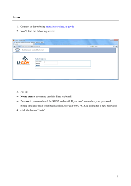
User Guide
Model 412300A Current Calibrator
Introduction
Congratulations on your purchase of the Extech Current Calibrator Model 412300A. The
412300A can measure/source current and can also power a current loop. A built-in five
location memory can store customized calibration current output steps. The Oyster
Series meters have a convenient flip up display with neck-strap for hands-free operation.
This meter is shipped fully tested and calibrated and, with proper use, will provide years
of reliable service.
Meter Description
1.
LCD display
2.
Battery Compartment
3.
AC adaptor jack
4.
Calibration Cable input
5.
Function switch
6.
Neck-strap posts
7.
Keypad
1
7
6
2
4
6
2
3
5
412300A-EU-EN-V3.3-1/11
Keypad and Switch Descriptions
POWER BUTTON and AUTO POWER OFF FEATURE
1. Use the POWER button to turn the unit ON or OFF. When the unit is powered up, a
short self-test will ensue after which the display will stabilize.
2. This meter can either be powered by one 9V battery or an AC adapter.
3. When the battery symbol appears on the LCD display, replace the battery as soon as
possible. Low battery power may cause inaccurate readings and erratic meter
operation.
4. This instrument is equipped with Auto Power OFF which turns the meter off after 10
minutes of inactivity. To override this feature; press and hold the MODE button until the
display shows
activated).
(auto power off de-activated) or
(auto power off
FUNCTION SLIDE SWITCH
1. Slide the Function switch on the side of the meter to the desired function
(Source/Measure or Power/Measure).
2. In the Source/Measure position the meter can be used to generate current or measure
current (MODE button is used to choose Source or Measure).
3. In the Power/Measure position, the meter can power a current loop with 24Vdc and, at
the same time, measure the current.
MODE BUTTON
Press the MODE button to select either SOURCE (output) or MEASURE (input). This
applies when the Function switch is set to Source/Measure.
UNIT BUTTON
Press the UNIT button to select mA or % units.
▲▼ INCREASE / DECREASE BUTTONS
Use the ▲ ▼buttons to increase or decrease the output current value in the source
mode.
1.
Press the ▲ button once to increase the value in one digit steps.
2.
Press and hold the ▲ button to increase the value in 10 digit steps.
3.
Press and hold the ▲ button >2 sec and then press the ▼ to increase the value in
100 digit steps
4.
To decrease the value, use the ▼ button as described above.
ZERO BUTTON
The ZERO button manually zeros the display in the MEASURE mode.
1.
Set the meter to the MEASURE mode
2.
Short the input jack
3.
Press and release the ZERO button
3
412300A-EU-EN-V3.3-1/11
MEM BUTTON
The memory feature provides the user with five (5) user programmable source values for
stepped calibration outputs. The feature is available for mA and % units in the SOURCE
mode. The stored values are kept in non-volatile memory (memory that is retained even
after power is removed from the calibrator).
Source from the stored memory values:
1.
Select the Source mode as described earlier
2.
Press the MEM button. The M1 icon (memory location 1) will appear in the display
and the value stored in that location will be displayed and sourced.
3.
Repeated pressing of the MEM button will step through the 5 memory locations.
NOTE: The “SOURCE” icon will blink when the output value has not reached a
stable level. The common cause for the “SOURCE” icon to remain blinking is that the
load impedance is too high in the current mode.
Storing values into memory:
1.
As described above, select and display a memory location (M1, 2, 3, 4, or 5)
2.
Use the ▲ ▼buttons to adjust the display to the desired source value.
3.
Press and hold the MEM button for > 2 seconds. The displayed value will be stored
in the displayed memory location.
Default memory values.
Five common source values are permanently programmed in memory as the default
values. These values can be replaced by user selected values.
To reset the meter to the default memory values:
1.
Turn the meter on and select the SOURCE mode.
2.
Press and hold the POWER button until
appears in the display and then
release the POWER button. The memory locations will revert to the default values.
Default Memory Values
M1
M2
M3
M4
M5
mA
4mA
8mA
12mA
16mA
20mA
%
0%
25%
50%
75%
100%
4
412300A-EU-EN-V3.3-1/11
Modes of Operation
MEASURE (Input) Mode of Operation
In this mode, the unit will measure up to 50mADC.
1.
Slide the function switch to the SOURCE/MEASURE position.
2.
Turn the meter ON
3.
Press the MODE button to select MEASURE
4.
Connect the Calibration Cable to the meter.
5.
Connect the Calibration Cable to the device or circuit under test.
6.
Read the measurement on the LCD display.
SOURCE (Output) Mode of Operation
In this mode, the unit can source current up to 24mADC at 1000 ohms
1.
Slide the Mode switch to the SOURCE/MEASURE position
2.
Turn the meter ON
3.
Press the MODE button to select SOURCE
4.
Use the UNIT button to select % or mA units of measure
5.
Connect the Calibration Cable to the meter
6.
Connect the Calibration Cable to the device or circuit under test
7.
Use the ▲ ▼buttons to select the desired output value. Use the LCD display to
verify the output level. Alternatively, use the stored calibration values in memory as
described in the MEM button section.
8.
Note that while the SOURCE display icon is blinking the calibrator is preparing to
provide an output but only after the icon stops blinking will the current actually be
sourced.
9.
For the -25% to 125% output range the output is 0 to 24mA. Refer to the Table
below.
Display
25%
0%
25%
50%
75%
100%
125%
mA
output
0mA
4mA
8mA
12mA
16mA
20mA
24mA
POWER/MEASURE Mode of Operation
In this mode the unit can measure current up to 24mA and power a 2-wire current loop.
The loop voltage is 24V.
1.
Slide the function switch to the POWER/MEASURE position.
2.
Turn the meter ON
3.
Connect the Calibration Cable to the meter.
4.
Connect the Calibration Cable to the loop. Open the current loop at any convenient
location along the signal path.
5.
Read the measurement on the LCD display.
6.
Use the UNIT button to select % or mA units of measure. In “%” mode the display
will read from -25.0 to +230.0% representing 0.00 to 50.00mA.
5
412300A-EU-EN-V3.3-1/11
Specifications
General Specifications
Display
Meter Power
Auto Power OFF
9999 count LCD
9 volt battery or AC adaptor
Meter automatically powers off after 10 minutes of
inactivity
24mADC at 1000 ohms
5ºC to 40ºC (41ºF to 104ºF)
o
o
o
o
-20 C to 60 C (- 4 F to 140 F)
Max 80% up to 31ºC (87ºF) decreasing linearly to 50% at
40ºC (104ºF)
<80%
2000meters (7000ft.) maximum
96 x 118 x 45mm (3.8 x 4.7 x 1.8") folded
340g (12 oz.)
9V battery, AC Adaptor and calibration cable with spade
lugs
Current output capability
Operating Temperature
Storage Temperature
Operating Humidity
Storage Humidity
Operating Altitude
Dimensions
Weight
Accessories Supplied
Range Specifications
Mode
Function
Measure
Source
Power
Range (Resolution)
Current
0 to 50mA (0.01mA)
Percent (%)
-25% to +230% (0.1%)
Current
0 to 24mA (0.01mA)
Percent (%)
-25% to +125% (0.1%)
Loop Power
24VDC, <50mA
Accuracy (% of reading
± (0.075% + 1 digit) or ± 3 digits
(whichever is greater)
Battery Replacement
When the battery symbol appears on the LCD, replace the 9V battery as soon as
possible.
1. Open the calibrator’s lid as far as possible.
2. With a coin or wide blade screwdriver, open the battery compartment moving in the
direction of the arrow embossed on the compartment cover (location of
compartment is identified in the meter description section).
3. Replace the battery and close the battery compartment cover.
You, as the end user, are legally bound (Battery ordinance) to return all used
batteries and accumulators; disposal in the household garbage is prohibited!
You can hand over your used batteries / accumulators at collection points in your
community or wherever batteries / accumulators are sold!
Disposal: Follow the valid legal stipulations in respect of the disposal of the
device at the end of its lifecycle
Copyright © 2011 Extech Instruments Corporation (a FLIR company)
All rights reserved including the right of reproduction in whole or in part in any form.
6
412300A-EU-EN-V3.3-1/11
Scaricare