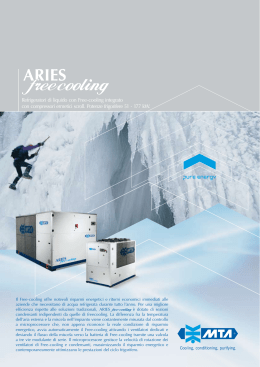
IT
EN
2
1
NOTE
2
CWFR F 320 ST WH
CWFR B 135 ST WH
REFRIGERATORI DI LIQUIDO CON CONDENSAZIONE AD
ARIA E COMPRESSORI SCROLL
WATER CHILLER AIR CONDENSER WITH SCROLL
COMPRESSORS
I refrigeratori di liquido della serie CWFR sono progettati per
sfruttare il “free cooling”, ossia lo smaltimento diretto all’esterno del
carico termico dell’ambiente condizionato.
Le macchine sono utilizzate in ambienti in cui il carico termico da
smaltire è elevato durante tutto l’anno, quindi anche nella stagione
invernale.
In questo caso la temperatura esterna è sensibilmente inferiore di
quella dell’ambiente da condizionare. L’acqua alle utenze viene
refrigerata, quindi, attraverso una batteria alettata posizionata
all’esterno, invece che dal ciclo frigorifero.
In questo modo si ottiene un’elevata efficienza energetica stagionale,
riducendo i consumi al solo assorbimento dei ventilatori.
The liquid chillers of the CWFR Series are designed to take
advantage of the “free-cooling”, that is the direct rejection to the
external environment of the thermal load of the conditioned room.
These systems are used in rooms where the thermal load is high
during all year, even in winter.
In this case, the external temperature is rather lower than the temperature of the controlled room. Thus the supply water is cooled through
an external finned coil, instead of the refrigerating cycle.
In this way a high seasonal energy efficiency is achieved, reducing
the energy consumptions to the fan absorption.
CONFIGURAZIONE DELL’UNITA’ STANDARD
CONFIGURATION DE L’UNITÉ STANDARD
9 FRAME, galvanized steel frame, powder painting, with solid lifting
base. RAL 7035 colour.
9 STRUTTURA di contenimento in lamiera zincata e verniciata a
polvere con solido basamento per il sollevamento, colore RAL
7035.
9 COMPRESSORE SCROLL con resistenza carter.
9 EVAPORATORE A PIASTRE, saldo brasate in acciaio inox AISI
316 con sonda antigelo e pressostato differenziale / flussostato a
protezione.
9 BATTERIA ALETTATA CONDENSANTE, con tubi di rame e
alette in alluminio protette da griglia metallica.
9 SCROLL COMPRESSOR, with crankcase electrical heater.
9 PLATE EVAPORATOR, brazed plates in stainless steel AISI 316,
with antifreeze thermostat and pressure differential switch/flow
switch to protect the refrigerant circuit.
9 FINNED COIL CONDENSER, with copper tubes and aluminum
fins, protected by metallic guards.
3
2
1
9 VENTILATORI ASSIALI.
9 BATTERIA ALETTATA AD ACQUA CON VALVOLA A TRE VIE
posta in serie all’evaporatore, che consente le tre diverse modalità
di funzionamento descritte sotto.
9 CIRCUITO FRIGORIFERO, eseguito secondo normativa PED,
completo di valvola termostatica, filtro, spia del liquido, rubinetto di
intercettazione, valvola di sicurezza e pressostati di alta e bassa
pressione.
9 QUADRO ELETTRICO con sezionatore generale e relè sequenza
fase.
9 CONTROLLO A MICROPROCESSORE a 16 bit e memoria flash.
9 REFRIGERANTE R410A, con ODP nullo e glide di temperatura
trascurabile.
9 AXIAL FANS.
9 WATER FINNED COIL WITH 3-WAY VALVE, downstream the
evaporator, it manages the three different running modes (see
below).
9 REFRIGERANT CIRCUIT, according to PED directive, with
thermostatic valve, filter, liquid sight glass, shut-off valve and high
and low pressure switches.
9 ELECTRICAL BOARD, with master circuit breaker and phase
relays.
9 MICROPROCESSOR CONTROLLER, 16 bit and flash memory
board.
9 R410A REFRIGERANT, null ODP and negligible temperature
glide.
IDENTIFICAZIONE DELLE UNITA’
IDENTIFICATION DES UNITÉS
CWFR
B
160
ST
WH
1
2
3
4
5
1 SERIE:
CWFR – gruppi refrigeratori di liquido condensati ad aria con
compressori ermetici scroll ed evaporatori a piastre
1 SERIE:
CWFR – water chiller air condensers with scroll compressors and
plate evaporators
2 MODELLO:
M = mono compressore
B = due compressori; i compressori sono connessi in tandem su un
circuito frigorifero
F = quattro compressori; i compressori sono connessi in tandem a
due a due su due circuiti frigoriferi
S = sei compressori; i compressori sono connessi in tandem a tre a
tre su due circuiti frigoriferi.
2 MODEL:
M = single compressor
B = two-compressors; the compressors are in tandem layout, in a
single refrigerating circuit
F = four-compressors; the compressors are in tandem layout, in
two refrigerating circuits
S = six-compressors; the compressors are in tandem layout, in two
refrigerating circuits.
3 VERSIONE:
ST = standard
LN = silenziata
3 VERSION:
ST = standard
LN = low noise
4 ALLESTIMENTO:
WH = unità priva di modulo idronico
MH = unità con modulo idronico
MS = unità con modulo idronico e serbatoio inerziale.
4 SET-UP:
WH = without hydronic module
MH = with hydronic module
MS = with hydronic module and buffer tank.
RUNNING MODES
MODALITA’ DI FUNZIONAMENTO
a) Funzionamento estivo
L’acqua viene refrigerata attraverso il normale ciclo frigorifero. La
batteria di free-cooling viene bypassata tramite una valvola a tre vie.
a) Summer mode
The supply water is cooled down by the regular refrigerating cycle.
The free-cooling finned coil is by-passed through a 3-way valve.
4
b) Stagione intermedia
Quando la temperatura esterna risulta essere 1°C inferiore
alla temperatura di ritorno dell’acqua all’utenza, la valvola a tre
vie alimenta la batteria di free-cooling. L’intera portata d’acqua
subisce, quindi,un pre-raffreddamento, mentre i compressori
lavorano a carico parziale per integrare il raffreddamento,
assicurando la resa richiesta.
Questa fase è particolarmente importante, specialmente alle
medie latitudini, poiché si concentra il maggior numero di ore di
funzionamento del sistema.
b) Intermediate season mode
When the external air temperature is 1°C lower than the supply
water, the 3-way valve feeds the free-cooling finned coil. The
whole water mass flow is pre-cooled, while the compressors run at
part load, to maintain the set-point conditions.
This control mode is particularly important at mean latitudes:
systems operate under these conditions for the largest part of life
time
c) Funzionamento invernale
L’acqua di ritorno dalle utenze viene refrigerata solamente
tramite la batteria di free cooling, sfruttando la bassa temperatura
esterna; la temperatura dell’acqua viene controllata tramite la
valvola a tre vie modulante. In questo caso i consumi sono
ridotti al solo assorbimento dei ventilatori, massimizzando così
l’efficienza energetica.
c) Winter mode
The supply water is cooled down in the free-cooling finned coil,
taking advantage of the low external temperature. The water
temperature is controlled by the 3-way modulating valve.
Thus energy consumptions are reduced to the fan absorption,
maximizing the energy efficiency.
REGOLAZIONE
CONTROL MODE
La regolazione è un aspetto fondamentale per la gestione di un
impianto ai carichi parziali. Grazie a varie possibilità di gestione,
le unità FR sono in grado di assicurare la massima capacità di
adattamento alle diverse esigenze.
Il controllo viene effettuato tramite la gestione dei compressori e della
valvola a tre vie modulante.
Il controllo dei compressori consente di ottimizzare il loro
funzionamento ai carichi parziali.
La valvola a tre vie modulante consente il controllo della temperatura
dell’acqua alle utenze (in caso di funzionamento invernale).
The control logic is a key factor for a system management at part
loads. Through various management options, FR units are able to
assure the highest adaptation to different requirements.
The control is performed through the management of compressors
and 3-way modulating valve.
The compressor management allows the optimization of their running
at part loads.
The 3-way modulating valve performs the control of the supply water
temperature (in case of winter running).
5
2
1
CONTROLLO REMOTO
REMOTE CONTROL
Le unità CWFR sono state realizzate per permettere la
connessione in rete per mezzo di sistemi di supervisione che
consentono il controllo remoto delle principali funzioni del sistema.
Inoltre è possibile collegare le unità FR ad un sistema BMS per
mezzo di appositi convertitori di protocollo forniti come accessori
opzionali (ModBus, Echelon, BacNet).
CWFR units are designed to allow the network connection by means
of supervision systems. They allow the remote control of the main
functions of the system. In addition, it is possible to connect the FR
units to a BMS system by protocol converters, provided as optional
(ModBus, Echelon, BacNet).
ACCESSORI DISPONIBILI
ACCESSORIES
•
•
•
•
•
•
•
•
•
•
•
•
•
RCP: Pannello di comando remoto
SB5: Scheda seriale del tipo RS485
ACB: Scheda orologio per storicizzazione allarmi
HLM: Manometri di alta e bassa pressione refrigerante
CRV: Rubinetti aspirazione e mandata compressori
SVL: valvola solenoide sulla linea del liquido
RSA: Antivibranti in gomma
SSA: Antivibranti a molla
AFH: Resistenza antigelo
WSP: Wireless Service Pack per il service remoto via SMS
YFS: Filtro a “Y” con rete in acciaio inox
PIH: Pompe con prevalenza maggiorata fino a 400kPa
BCP: Trattamento anticorrosione per installazioni in ambienti
aggressivi
• RLD: Verniciatura serie “RAL” diversa dalla standard.
•
•
•
•
•
•
•
•
•
•
•
•
•
RCP: Remote control panel
SB5: RS485 type serial board
ACB: Alarm log clock board
HLM: High/low refrigerant pressure gauges
CRV: Compressor suction/discharge valves
SVL: Solenoid valve in the liquid line
RSA: Rubber shock absorbers
SSA: Spring shock absorbers
AFH: Antifreeze electrical heaters
WSP: Wireless Service Pack for remote service via SMS
YFS: “Y” filter with stainless steel mesh
PIH: Pump with increased head up to 400kPa
BCP: Battery corrosion proofing for installations in aggressive
environments
• RLD: Painting “RAL” serie other than standard.
RISPARMIO ENERGETICO CON IL FREE COOLING
ENERGY SAVING WITH FREE COOLING
La tecnica del Free Cooling consente rilevanti risparmi energetici, in
funzione della temperatura dell’aria esterna.
Sono in seguito riportati alcuni esempi di consumi mensili di due
unità della stessa potenza frigorifera, con e senza Free cooling. Sono
state prese in considerazione quattro città europee: Milano, Parigi,
Francoforte e Stoccolma.
Il risparmio energetico annuale di una unità CWFR, può arrivare al
50% dei consumi totali, come nel caso di Stoccolma.
The Free cooling technique allows remarkable energy savings,
depending on the external air temperature.
In the following, some examples of monthly energy consumptions
of two units of the same cooling capacity, with and without Free
cooling, are reported. Four European cities (Milan, Paris, Frankfurt
and Stockholm) have been considered.
The annual energy saving of a CWFR unit can reach the 50 % of the
total energy consumptions, as for Stockholm.
Consumi calcolati per
• Volume interno ambiente: 300 m3
• Trasmittanza media pareti: 0,4 W/m2K
Risparmio energetico
Energy consumptions calculated for:
• Inside room volume: 300m3
• Average wall transmittance: 0,4 W/m2K
• Ricambi orari: 0,5 Vol/h
• Carichi interni: 200 kW
Consumo energetico
con Free-Cooling
Energy saving
6
• Hourly air intake: 0,5 Vol/h
• Inside thermal load: 200 kW
Energy consumption
with Free-Cooling
CWFR
DATI TECNICI - TECHNICAL DATA
R410A
WATER
REFRIGERATORI DI LIQUIDO CON BATTERIA DI FREE COOLING, condensati ad aria (CWFR)
WATER CHILLERS WITH FREE COOLING FINNED COIL, with air condensation (CWFR)
040
053
068
080
105
135
160
210
270
320
405
480
Resa frigorifera senza FREE-COOLING 1)
Cooling capacity without FREE-COOLING 1)
kW
39,4
53,2
68,2
79,8
106,4
136,3
159,6
212,8
272,7
319,1
409,0
478,7
Potenza elettrica assorbita senza FREE-COOLING 1)
Electrical power input without FREE-COOLING 1)
kW
15,4
21,2
27,5
27,7
37,0
52,4
61,7
82,6
104,4
123,1
159,9
186,1
Resa frigorifera con FREE-COOLING (T ext = 2°C)
Cooling capacity with FREE-COOLING (T ext = 2°C)
kW
32,2
50,9
59,6
60,1
64,7
96,8
131,1
186,0
193,6
262,2
368,0
450,0
Resa frigorifera con FREE-COOLING (T ext = 5°C)
Cooling capacity with FREE-COOLING (T ext = 5°C)
kW
24,7
39,1
45,8
46,2
49,6
74,3
100,0
142,0
148,6
200,0
282,0
344,0
Potenza elettrica assorbita con FREE-COOLING
Electrical power input with FREE-COOLING
kW
2,7
3,8
5,1
1,5
2,2
7,6
9,4
13,0
14,8
18,4
25,5
29,1
Portata d’acqua
Water flow
m3/h
7,6
10,2
13,1
15,3
20,4
26,1
30,6
40,8
52,2
61,1
81,5
95,2
Perdite di carico batteria FREE-COOLING
FREE-COOLING finned coil pressure drop
kPa
27,3
18,4
29,8
20,3
34,2
23,9
38,5
40,8
23,9
38,5
40,8
56,3
Perdite di carico evaporatore
Evaporator pressure drop
kPa
43,4
44,3
39,8
45,4
46,2
46,6
46,0
46,6
46,1
47,1
56,5
45,9
N.ro / N.ro circuiti frigo
Number / Circuits
-
1/1
1/1
1/1
1/1
2/1
2/1
2/1
4/2
4/2
4/2
6/2
6/2
Tipo
Type
-
Gradini di parzializzazione
Number of stages
-
1
1
1
1
2
2
2
4
4
4
6
6
m3/h
15500
25000
34000
34000
34000
51000
68000
85000
102000
136000
170000
205000
MODELLO - TYPE
SEZIONE RAFFREDDANTE - COOLING SECTION
COMPRESSORE - COMPRESSOR
Ermetico scroll / Hermetic scroll
SEZIONE VENTILANTE - FAN SECTION
Portata aria nominale
Nominal air flow
Tipo
Type
-
Numero dei ventilatori
Number of fans
-
2
2
2
2
2
3
4
5
6
8
10
12
Potenza nominale ventilatore
Fan nominal power input
kW
1,2
2,3
3,6
3,6
3,6
5,4
7,2
9,0
10,8
14,4
18,0
21,6
Max potenza assorbita
Max power input
kW
1,2
2,5
4,0
4,0
4,0
6,0
8,0
10,0
12,0
16,0
20,0
24,0
Centrifugo pale curve indietro con motore tipo EC / Centrifugal backward curve blade with EC type motor
SEZIONE ELETTRICA - ELECTRIC SECTION
Alimentazione
Power supply
-
Corrente di funzionamento
Nominal input current
A
24
36
45
49
67
86
94
129
169
183
251
273
Corrente max funzionamento
Max input current
A
38
55
69
83
106
134
162
208
264
320
394
478
Corrente di spunto
Max inrush current
A
198
219
264
324
270
329
403
270
329
403
329
403
dB(A)
77
78
79
80
81
82
83
83
84
84
85
86
Lunghezza
Lenght (L)
mm
1900
2200
2200
2200
2200
3240
4280
5320
4280
5320
6360
7380
Profondità
Depht (W)
mm
1100
1100
1100
1100
1100
1100
1100
1100
2200
2200
2200
2200
Altezza
Height (H)
mm
1570
2255
2255
2255
2255
2255
2255
2255
2310
2310
2310
2310
kg
550
850
930
950
970
1600
1850
2050
2580
3380
3600
3800
400 / 3N / 50Hz
LIVELLO SONORO - SOUND LEVEL 2)
Potenza sonora totale
Sound power level
DIMENSIONI - DIMENTIONS
Peso - DXA
Weight - DXA
1) Acqua 7-12°C - 51°C condensazione/ Water 7-12°C - 51°C condensing; Refrigerante/Refrigerant fluid R410A
2) Livello di pressione sonora riferita ad 1mt dall’unità n campo libero / sound pressure level @ 1 mt in free field
7
EQUINOXE Kft.
1097 Budapest, Gubacsi út 24.
Citypoint 9 Business Park A épület
Mobil: +36 (30) 768-6457
Tel: +36 (1) 273-3206
Fax: +36 (1) 273-3233
E-mail: [email protected]
Skype: equinoxe.hu, www.equinoxe.hu
Shop: http://shop.equinoxe.hu
Scarica