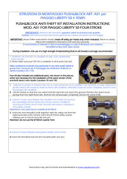
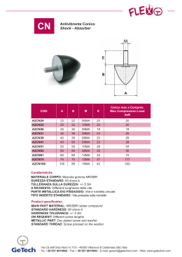
ISTRUZIONI DI MONTAGGIO PUSH&BLOCK ART. A01 per
APRILIA SCARABEO 50 E 100 4 TEMPI
PUSH&BLOCK ANTIANTI-THEFT KIT INSTALLATION INSTRUCTIONS MOD. A01
FOR
FOR APRILIA SCARABEO 50 AND 100 – 4-STROKE (4T)
IMPORTANTE:
IMPORTANTE: Attenersi alle istruzioni, spezzare i perni di sicurezza
sicurezza solo quando indicato.
indicato
Non verrà riconosciuta alcuna garanzia per cattiva esecuzione del montaggio.
IMPORTANT:
IMPORTANT: Please follow instructions closely. Break off safety pin heads only when indicated.
Failure to closely follow the installation instructions will void any warranty.
Si raccomanda di utilizzare in fase di assemblaggio su tutte le filettature una sostanza frenafiletti di tipo forte.
loctite)
forte (loctite
loctite
During installation, the use of a high strength threadthread-locking fluid on all threads is strongly recommended
1. Verificare che il kit A01 sia completo di tutti i suoi componenti, Come da foto.
1. Please make sure your A01 kit is complete in all its parts (see pic).
Nella confezione troverete due particolari in più oltre quelli visibili in questa foto,
necessari
necessari per il montaggio del medesimo antifurto su Aprilia Piaggio Liberty 50.
Your kit also includes two additional parts, not shown in the picture, which are
necessary for the installation of this same version of the antianti-theft device onto
Piaggio Liberty 50.
2. Sollevare il veicolo in maniera tale che la ruota posteriore ed il cavalletto non tocchino al suolo. Rimuovere dal lato
destro del veicolo le molle di ritorno del cavalletto. Smontare il tubo di scarico completo. Estrarre l’asse di sostegno del
cavalletto.
2. Lift the vehicle so that the rear wheel and the stand do not touch the ground. Remove the stand return springs from
the right-hand side. Remove the exhaust pipe completely. Extract the stand shaft.
3. inserire il nuovo asse filettato del cavalletto con il dado di sicurezza preassemblato dal lato destro del veicolo, inserire rondella di sicurezza Ø 27mm
come in foto, facendo attenzione a rispettare il verso della conicità.
Attenzione: non usare qui la rondella da Ø 30mm
3. Insert the new threaded shaft together with the safety nut from the right-hand
side of the vehicle; the Ø 27mm safety washer must be inserted making sure it is
faced correctly (see pic).
Attention: Do not use the Ø 30mm washer here
4. inserire il mozzo filettato nella piastra mobile come in foto
4. Insert the threaded hub into the movable plate (see pic).
5. Innestare l’insieme sul cavalletto, come in foto, avvitando l’asse di soli 2 giri
5. Insert the part assembled at point 4 onto the stand as shown in the picture,
turning the shaft only twice
Instructions may also be found and downloaded at www.capobranco.com
6. Svitare il dado dell’asse anteriore di sostegno del motore dal lato
sinistro
A questo punto inserire sull’asse indicato in foto la rondella in gomma
presente nel kit.
6. From the left-hand side, unscrew the nut from the front engine frame
shaft.
At this point, insert the rubber washer included in the kit onto the shaft,
as shown in the picture.
7. Inserire la piastra fissa negli assi del cavalletto e del supporto motore
anteriore vedi foto
7. Insert the fixed plate onto both the shafts of the stand and the front
engine frame (see pic)
8.
Avvitare sull’asse anteriore del motore il dado di sicurezza con relativa
rondella di sicurezza Ø 30 mm , come è stato fatto al punto 3,
ricordandosi di rispettare il verso della rondella di sicurezza. Serrare a
fondo senza spezzare la testa del dado.
dado. Vedi foto
8. Screw the safety nut with its Ø 30 mm washer onto the front engine
shaft, similarly to what was done at point 3, making sure the washer is
faced correctly. Tighten without breaking the safety nut off yet (see pic)
9. inserire una chiave piana nell’apposita sede sul mozzo filettato. Vedi foto.
Attenzione: la chiave piana da 19 mm non va rimossa fino al
completamento di tutte le operazioni.
Mantenendo la chiave da 19 mm nella sua posizione, avvitare a fondo l’asse
del cavalletto (con il perno di sicurezza dal lato destro) con chiave da 22
mm., senza spezzare la testa del dado di sicurezza.
9. Insert a 19 mm open-end wrench in the special holding spot on the
threaded hub (see pic)
Attention: the 19 mm openopen-end wrench must not be removed from this
position until all operations are completed.
completed.
Holding the 19 mm wrench in place, tighten the stand shaft (with the
safety pin on the right-hand side) with a 22 mm wrench, without
without breaking
the safety pin head off yet (see pic),
10.
10 Senza estrarre ancora la chiave da 19 mm dalla sua sede, assemblare il
bullone di sicurezza con testa da 15 mm con la rondella di sicurezza Ø
26 mm, facendo attenzione a rispettare il verso della conicità, e la molla.
Vedi foto
10.
10. Still holding the 19mm wrench in place,
place assemble the 15 mm head safety
bolt with the Ø 26 mm washer, making sure it is facing in the correct
direction, and the spring (see pic)
11.Avvitare il tutto così assemblato sul mozzo dal lato sinistro, serrare a
fondo con chiave da 15 mm. mantenendo nella sua posizione la chiave
da 19, senza spezzare la testa del bullone.
bullone Vedi foto
11.Screw the part assembled at point 10 onto the hub from the left-hand
side. Tighten the bolt with a 15 mm wrench while holding the 19 mm
wrench in position, without breaking off the bolt head yet (see pic)
12.
12 A questo punto estrarre temporaneamente la chiave da 19 mm,
mm posizionare il veicolo a terra sostenuto dal suo
cavalletto, inserire e disinserire più volte l’antifurto verificando che tutto funzioni correttamente.
12.
12. You must now temporarily extract the 19 mm wrench,
wrench lower the vehicle back to the ground, and with the vehicle
being held up by its own stand, test the device is working correctly by repeatedly engaging and disengaging the
lock-button.
Instructions may also be found and downloaded at www.capobranco.com
13.
13 Inserire nuovamente la chiave da 19 mm nella sua sede e tenendola ben
salda, serrare dal lato destro il dado di sicurezza fino a spezzarne la testa.
testa
Vedi foto
13.
13. Reinsert the 19 mm wrench where it was before, and while holding it
firmly, tighten the safety nut from the right-hand side until its head
breaks off (see pic)
14.
14. A questo punto, tenendo sempre ben salda la chiave da 19 mm, con
chiave da 15 mm serrare a fondo anche il bullone di sicurezza del lato
sinistro fino a spezzarne la testa.
testa Vedi foto
14. Still holding the 19 mm wrench in position, also tighten the safety bolt
on the left-hand side using a 15 mm wrench until the safety bolt head
breaks off (see pic)
15. A questo punto serrare sull’asse anteriore del motore il dado di sicurezza fino a spezzarne la testa.
testa Vedi foto al punto
8
15.
15. At this point, tighten the safety nut on the front engine frame shaft until its head breaks off.
off See picture at point 8.
16. Riassemblare il tubo di scarico, rimontare le molle di ritorno del cavalletto nella posizione originale. Il lavoro è così
terminato. Complimenti per aver eseguito il montaggio
16. Put the exhaust pipe back in place, and also mount the stand return springs back in place. Installation of the antitheft device is now complete: congratulations!
IN CASO DI DUBBI OSSERVAREL’ESPLOSO DI MONTAGGIO E IL COMPLESSIVO DI MONTAGGIO
WHENEVER IN DOUBT, PLEASE REFER TO THE INSTALLATION MOUNTED AND EXPLODED VIEWS
VIEWS
Instructions may also be found and downloaded at www.capobranco.com
COMPLESSIVO DI MONTAGGIO DEL KIT A01 SU APRILIA SCARABEO 50 / 100 4T
ASSEMBLED VIEW OF KIT A01 MOUNTED ON APRILIA SCARABEO 50 / 100 4T (4(4-STROKE)
ESPLOSO DI MONTAGGIO DEL KIT A01 SU APRILIA SCARABEO 50 / 100 4T
EXPLODED VIEW OF KIT A01 MOUNTED ON APRILIA SCARABEO 50 / 100 4T (4(4-STROKE)
Ø 30 mm SAFETY WASHER
RUBBER WASHER
SAFETY BOLT
SAFETY NUT
THREADED HUB
SAFETY NUT
SHAFT
FIXED PLATE
SPRING
Ø 26 mm SAFETY WASHER
MOVABLE PLATE
Ø 27 mm
SAFETY WASHER
Instructions may also be found and downloaded at www.capobranco.com
Scaricare