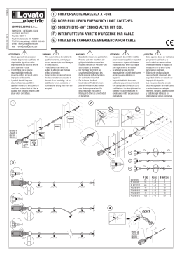
ECO 24
OPERATORE PER CANCELLI A BATTENTE
OPÉRATEUR POUR PORTAILS À BATTANT
OPERATOR FOR LEAF GATES
TORANTRIEB FÜR FLÜGELTORE
OPERADOR PARA CANCELAS DE BATIENTE
Operatore
Operateur
Operator
Torantrieb
Operador
codice
code
code
code
codigo
Alimentazione
Alimentation
Power Supply
Stromspannung
Alimentacion
Peso max anta
Poids maxi battant
Max leaf weight
Max. Torgewicht
Peso max hoja
Spinta
Poussée
Thrust
Schubkraft
Empuje
Spinta max
Poussée maxi
Max thrust
Max Schubkraft
Empuje max.
ECO 24
12007440
24 Vdc
250 kg / 550 lbs
100 kg / 220 lbs
140 kg / 309 lbs
ITALIANO pag. 05 / FRANÇAIS pag. 09 / ENGLISH page 13 / DEUTSCH pag. 17 / ESPAÑOL pag. 21
6-1624090 rev.04 20/10/2008
I
DE SECURITE
F INSTRUCTIONS
IMPORTANTES POUR L’INSTALLATION
ISTRUZIONI DI SICUREZZA IMPORTANTI
PER L’INSTALLAZIONE
- ATTENZIONE PER LA SICUREZZA DELLE PERSONE É IMPORTANTE
CHE VENGANO SEGUITE TUTTE LE ISTRUZIONI
- ATTENTION POUR LA SECURITE DES PERSONNES IL EST IMPORTANT
QUE TOUTES LES INSTRUCTIONS SOIENT SUIVIES
SUIVRE TOUTES LES INSTRUCTIONS D’INSTALLATION
SEGUIRE TUTTE LE ISTRUZIONI DI INSTALLAZIONE
1° - Ce livret d’instructions est adressé exclusivement à un
personnel spécialisé qui connaît les critères de construction et
les dispositifs de protection contre les accidents concernant les
portails, les portes et les grandes portes motorisés (s’en tenir aux
normes et aux lois en vigueur).
2° - L’installateur devra délivrer à l’utilisateur final un livret
d’instruction en accord à la EN 12635.
3° - L’installateur avant de procéder à l’installation, doit prévoir
l’analyse des risques de la fermeture automatisée finale et la mise
en sécurité des points identifiés dangereux (en suivant les
normes EN 12453/EN 12445).
4° - Le câblage des divers composants électriques externes à
l’opérateur (par exemple photocellules, clignotants, etc) doit être
effectué selon la EN 60204-1 et les modifications apportées à
celle-ci dans le point 5.2.2 de la EN 12453.
5° - Le montage éventuel d’un tableau pour la commande manuelle
du mouvement doit être fait en positionnant le tableau de façon à
ce que la personne qui l’actionne ne se trouve pas en position de
danger ; de plus, il faudra faire en sorte que le risque
d’actionnement accidentel des boutons soit réduit.
6° - Tenir les commandes de l’automatisme (tableau, télécommande,
etc) hors de portée des enfants. Les commandes doivent être
placées à une hauteur minimum de 1,5 m du sol et hors du rayon
d’action des parties mobiles.
7° - Avant l’exécution de toute opération d’installation, de réglage,
d’entretien de l’installation, couper le courant en agissant sur
l’interrupteur magnétothermique à cet effet, branché en amont de
l’installation.
1° - Questo libretto d'istruzioni è rivolto esclusivamente a del
personale specializzato che sia a conoscenza dei criteri
costruttivi e dei dispositivi di protezione contro gli infortuni per i
cancelli, le porte e i portoni motorizzati (attenersi alle norme e alle
leggi vigenti).
2° - L’installatore dovrà rilasciare all’utente finale un libretto di
istruzioni in accordo alla EN 12635.
3° - L’installatore prima di procedere con l’installazione deve
prevedere l’analisi dei rischi della chiusura automatizzata finale e
la messa in sicurezza dei punti pericolosi identificati (seguendo le
norme EN 12453/EN 12445).
4° - Il cablaggio dei vari componenti elettrici esterni all’operatore (ad
esempio fotocellule, lampeggianti, ecc.) deve essere effettuato
secondo la EN 60204-1 e le modifiche a questa apportate dal
punto 5.2.2 della EN 12453.
5° - L’eventuale montaggio di una pulsantiera per il comando manuale
del movimento deve essere fatto posizionando la pulsantiera in
modo che chi la aziona non si trovi in posizione pericolosa; inoltre
si dovrà fare in modo che sia ridotto il rischio di azionamento
accidentale dei pulsanti.
6° - Tenete i comandi dell'automatismo (pulsantiera, telecomando
etc.) fuori dalla portata dei bambini. I comandi devono essere
posti ad un’altezza minima di 1,5m dal suolo e fuori dal raggio
d’azione delle parti mobili.
7° - Prima di eseguire qualsiasi operazione di installazione,
regolazione, manutenzione dell’impianto, togliere la tensione
agendo sull’apposito interruttore magnetotermico collegato a
monte dello stesso.
LA DITTA ALLMATIC NON ACCETTA NESSUNA RESPONSABILITÀ
per eventuali danni provocati dalla mancata osservanza
nell'installazione delle norme di sicurezza e delle leggi attualmente in
vigore.
LA SOCIETE ALLMATIC N’ACCEPTE AUCUNE RESPONSABILITE
pour d’éventuels dommages provoqués par la non-observation dans
l’installation, des normes de sécurité et des lois actuellement en
vigueur.
1° - Se non é previsto nella centralina elettrica, installare a monte
della medesima un'interruttore di tipo magnetotermico
(onnipolare con apertura minima dei contatti pari a 3mm) che
riporti un marchio di conformità alle normative internazionali. Tale
dispositivo deve essere protetto contro la richiusura accidentale
(ad esempio installandolo dentro quadro chiuso a chiave).
2° - Per la sezione ed il tipo dei cavi la ALLMATIC consiglia di
utilizzare un cavo di tipo H05RN-F con sezione minima di 1,5mm2
e comunque di attenersi alla norma IEC 364 e alle norme di
installazione vigenti nel proprio Paese.
3° - Posizionamento di un’eventuale coppia di fotocellule: Il raggio
delle fotocellule deve essere ad un’altezza non superiore a 70 cm
dal suolo e ad una distanza dal piano di movimento dell’anta non
superiore a 20 cm. Il loro corretto funzionamento deve essere
verificato a fine installazione in accordo al punto 7.2.1 della EN
12445.
4° - Per il soddisfacimento dei limiti imposti dalla EN 12453, se la
forza di picco supera il limite normativo di 400 N è necessario
ricorrere alla rilevazione di presenza attiva sull’intera altezza del
cancello (fino a 2,5m max) - Le fotocellule in questo caso sono da
applicare all’esterno tra le colonne ed all’interno per tutta la corsa
della parte mobile ogni 60÷70cm per tutta l’altezza delle colonne
del cancello fino ad un massimo di 2,5m (EN 12445 punto
7.3.2.1) - es. colonne alte 2,2m => 6 coppie di fotocellule - 3
interne e 3 esterne (meglio se dotate di sincronismo - 6 FIT
SYNCRO con 2 TX SYNCRO).
1° - Si la centrale électrique ne dispose d'aucun interrupteur, il faut en
installer un de type magnétothermique en amont de cette
dernière (omnipolaire avec ouverture minimale des contacts
correspondant à 3mm); la marque de cet interrupteur devra être
en conformité avec les normes internationales. Ce dispositif doit
être protégé contre toute remise en fonction accidentelle (ex. en
l’installant dans un coffre fermant à clé).
2° - En ce qui concerne la section et le type des câbles, le conseil de
la ALLMATIC est celui d'utiliser un câble de type H05RN-F
présentant une section minimale de 1,5mm2 et, quoi qu'il en soit,
de se conformer à la norme IEC 364, ainsi qu'aux normes
d'installation en vigueur dans le pays de destination.
3° - Positionnement d’un éventuel jeu de photocellules : le faisceau
des photocellules ne doit pas être à une hauteur supérieure à 70
cm du sol et 20 cm du bord du vantail. Leur correct effectivité
fonctionnement doit être vérifié terminant l’installation, selon le
point de la 7.2.1 de la EN 12445.
4° - Afin de satisfaire aux limites imposées par la norme EN 12453, si
la force d’impact dépasse la limite de 400N, il sera nécessaire de
détecter une présence sur la hauteur totale du portail (jusqu'à un
maximum de 2,5m) - Les cellules photo-électriques dans ce casci doivent être s'appliquent extérieurement entre les colums et
intérieurement pour toute la course de la pièce de mobil chaque
60÷70cm pour toute la taille de la colonne de la porte jusqu'à un
maximum de 2,5m (EN 12445 point 7.3.2.1) - exemple: taille 2,2m
de colonne = > 6 copies des cellules photo-électriques - 3
internes et 3 externes (meilleur si complet du dispositif de
syncronism - FIT SYNCRO avec TX SYNCRO).
CONSERVER SOIGNEUSEMENT CES INSTRUCTIONS
CONSERVARE CON CURA QUESTE ISTRUZIONI
N.B.:É obbligatoria la messa a terra dell'impianto
I dati descritti nel presente manuale sono puramente indicativi.
La ALLMATIC si riserva di modificarli in qualsiasi momento.
Realizzare l’impianto in ottemperanza alle norme ed alle leggi vigenti.
6-1624090 rev.04 20/10/2008
2
N.B.:La mise à terre de l'installation est obligatoire.
Les données figurant dans le présent manuel sont fournies à titre
purement indicatif. La ALLMATIC se réserve le droit de les modifier à
tout moment, sans aucun préavis. Effectuer l'installation en conformité
avec les normes et les lois en vigueur.
G
B
IMPORTANT SAFETY INSTRUCTIONS FOR THE
INSTALLATION
SICHERHEITS ANLEITUNGEN FÜR DIE
D WICHTIGE
INSTALLATIONEN
- ATTENTION FOR THE SAFETY OF THE PEOPLE IT IS IMPORTANT
TO FOLLOW ALL THE INSTRUCTIONS.
- ACHTUNG FÜR DIE SICHERHEIT DER PERSONEN IST ES WICHTIG,
DASS ALLE ANWEISUNGEN GENAU AUSGEFÜHRT WERDEN
ALLE INSTALLATIONSANLEITUNGEN BEFOLGEN
FOLLOW ALL INSTALLATION INSTRUCTIONS
1° - Diese Betriebsanleitung dient ausschließlich dem
Fachpersonal, welche die Konstruktionskriterien und die
Sicherheits-Vorschriften gegen Unfälle für Tore, Türen und
automatische Tore kennt (geltende Normen und Gesetze
beachten und befolgen).
2° - Der Monteur muss dem Endkunde eine Betriebsanleitung in
Übereinkunft der EN12635 überreichen.
3° - Vor der Installierung muss für die automatische Schließung und
zur Sicherheitsgewährung der identifizierten kritischen Punkte,
eine Risiko Analyse vorgenommen werden mit der
entsprechenden Behebung der identifizierten, gefährlichen
Punkte. (die Normen EN 12453/EN 12445 befolgend).
4° - Die Verkabelung der verschiedenen externen elektrischen
Komponenten zum Operator (z.B. Fotozellen, Blinker etc.) muss
nach EN 60204-1 ausgeführt werden, Änderungen davon nach
Punkt 5.2.2 der EN 12453.
5° - Die eventuelle Montage einer Schalttafel für den manuellen
Bewegungsbefehl muss so angebracht werden, dass der
Benutzer sich nicht in einer Gefahrenzone befindet, und dass,
das Risiko einer zufälligen nicht gewollten Aktivierung von
Schaltern gering ist.
6° - Alle Steuerungselemente (Schalttafel, Fernbedienung etc.)
gehören nicht in Reichweite von Kindern. Die Kommandos
müssen min. 1,5 m ab Boden und außerhalb des
Aktionsbereiches der mobilen Teile angebracht werden.
7° - Vor jeglichem Eingriff, sei es Installation, Regulation oder
Wartung der Anlage, muss vorher die Stromzufuhr unterbrochen
werden, den dafür bestimmten Magnetthermo-Schalter drücken,
der am Eingang der Anlage installiert ist.
1° - This handbook is exclusively addressed to the specialized
personnel who knows the constructive criteria and the protection
devices against the accidents for motorized gates, doors and
main doors (follow the standards and the laws in force).
2° - The installer will have to issue to the final user a handbook in
accordance with the EN 12635.
3° - Before proceeding with the installation, the installer must forecast
the risks analysis of the final automatized closing and the safety
of the identified dangerous points (following the standards EN
12453/EN 12445).
4° - The wiring harness of the different electric components external
to the operator (for example photoelectric cells, flashlights etc.)
must be carried out according to the EN 60204-1 and the
modifications to it done in the point 5.2.2 of the EN 12453.
5° - The possible assembly of a keyboard for the manual control of the
movement must be done by positioning the keyboard so that the
person operating it does not find himself in a dangerous position;
moreover, the risk of accidental activation of the buttons must be
reduced.
6° - Keep the automatism controls (push-button panel, remote control
etc.) out of the children way. The controls must be placed at a
minimum height of 1,5m from the ground and outside the range of
the mobile parts.
7° - Before carrying out any installation, regulation or maintenance
operation of the system, take off the voltage by operating on the
special magnetothermic switch connected upstream it.
THE ALLMATIC COMPANY DOES NOT ACCEPT ANY
RESPONSIBILITY for possible damages caused by the non
observance during the installation of the safety standards and of the
laws in force at present.
DIE FIRMA ALLMATIC ÜBERNIMMT KEINE VERANTWORTUNG für
eventuelle Schäden, die entstehen können, wenn die Installierungsvorschriften
die den gültigen Sicherheitsnormen entsprechen, nicht eingehalten werden.
INSTALLATIONSVORSCHRIFTEN BEACHTET WERDEN
KEEP THESE INSTRUCTIONS WITH CARE
1° - Wenn nicht bereits an der elektrischen Schaltzentrale
vorgesehen,
muss
vor
der
Schaltzentrale
ein
thermomagnetischer Schalter installiert werden (omnipolar, mit
einer minimalen Kontaktöffnung von 3 mm), der ein von den
internationalen Normen anerkanntes Konformitätszeichen besitzt.
Solch ein Geraet muss vor Vandalismus geschuetzt
werden(z.B.mit
einen
Schluesselkatsten
in
einem
Panzergehaeuse)
2° - ALLMATIC empfiehlt den Kabeltyp H05RN-F mit einem
minimalen Querschnitt von 1,5mm2 generell sollten die Normative
IEC 364 und alle anderen geltenden Montagenormen des
Bestimmungslandes eingehalten werden.
3°- Position des ersten paar Fotozellen: Der sollten nicht hoeher als
70cm vom Boden sein, und sollte nicht mehr als 20 cm entfernt
von der Achse des Tores sitzen (das gilt fuer Schiebe und
Drehtore). In Übereinstimmung mit dem Punkt 7.2.1 der EN 12445
Norm, ihr korrektes Funktionieren muß einmal überprüft werden.
4°- In Einklang mit der Norm EN12453, ist es bei Toren notwendig
eine komplette Sicherheitslieiste zu installieren, bei denen mehr
als 400N Kraft aufgewand werden muessen, um das Tor zum
anhalten zu bringen (Maximum von 2,5m anwenden) - Die
Fotozellen müssen in diesem Fall sein beantragen außen
zwischen den colums und innerlich das ganzes Rennen des mobil
Teils jede 60÷70cm für die ganze Höhe der Spalte des Gatters bis
zu einem Maximum von 2,5m - EN 12445 Punkt 7.3.2.1). Beispiel:
Spalte Höhe 2,2m => 6 Kopien von Fotozellen - 3 intern und 3
extern (besser, wenn komplett von der syncronism Eigenschaft FIT SYNCRO mit TX SYNCRO).
1° - Install a thermal magnetic switch (omnipolar, with a minimum
contact opening of 3 mm) before the control board, in case this is
not provided with it. The switch shall be guaranteed by a mark of
compliance with international standards. Such a device must be
protected against accidental closing (e.g. Installing it inside the
control panel key locked container).
2° - As far as the cable section and the cable kind are concerned,
ALLMATIC suggests to use an H05RN-F cable, with a minimum
section of 1,5mm2, and to follow, In any case, the IEC 364
standard and Installation regulations In force In your Country.
3° - Positioning of an eventual pair of photocells: The beam of the
photocells must be at an height not above the 70 cm from the
ground, and, should not be more than 20 cm away from the axis
of operation of the gate (Sliding track for sliding gate or door, and
the hinges for the swing gate). In accordance with the point 7.2.1
of EN 12445 their correct functioning must be checked once the
whole installation has been completed.
4° - In order to comply with the limits defined by the EN 12453 norm,
if the peak force is higher than the limit of 400N set by the norm,
it is necessary to use an active obstacle detection system on the
whole height of the gate (up to a maximum of 2,5m) - The
photocells in this case must be apply externally between the
colums and internally for all the race of the mobil part every
60÷70cm for all the height of the column of the gate up to a
maximum of 2,5m (EN 12445 point 7.3.2.1). example: column
height 2,2m => 6 copies of photocells - 3 internal and 3 external
(better if complete of syncronism feature - FIT SYNCRO with TX
SYNCRO).
N.B.: The system must be grounded
Data descallmaticed by this manual are only Indicative and ALLMATIC
reserves to modify them at any time. Install the system complying with
current standards and regulations.
6-1624090 rev.04 20/10/2008
3
ANMERKUNG: Die Erdung der Anlage ist obligatorisch
Die in diesem Handbuch aufgeführten Daten sind ausschließlich empfohlene
Werte. ALLMATIC behält sich das Recht vor, das Produkt zu jedem Zeitpunkt
zu modifizieren. Die Anlage muss in Übereinstimmung mit den gültigen Normen
und Gesetzen montiert werden.
E
S
IMPORTANTES INSTRUCCIONES DE SEGURIDAD
PARA LA INSTALACIÓN
- CUIDADO UNA INCORRECTA INSTALACIÓN PUEDE CAUSAR
GRAVES DAÑOS
SEGUIR TODAS LAS INSTRUCCIONES DE INSTALACIÓN
1° - Este manual de instrucciones está exclusivamente dirigido a
personal especializado que conozca los criterios de
construcción y de los dispositivos de protección contra
accidentes con cancelas, puertas y portales motorizados
(atenerse a las normas y a las leyes vigentes).
2° - El instalador tendrá que dar al utilizador final un manual de
instrucciones de acuerdo con la EN 12635.
3° - El instalador antes de proceder con la instalación tiene que hacer
una analisis de los riesgos del cierre automatizado final y la puesta
en seguridad de los puntos identificados como peligrosos
(siguiendo las normas EN 12453 / EN 12445).
4° - El cablaje de los varios componentes eléctricos externos al
operador (por ejemplo fotocélulas, los intermitentes, etc) tiene que
ser efectuado según la EN 60204-1 y a las modificas sucesivas
aportadas por el punto 5.2.2 della EN 12453.
5° - El eventual montaje de un panel de mandos para la gestión del
movimiento manual tiene que ser efectuado posicionando el
panel en modo que quién lo accione no se encuentre en una
posición peligrosa; además se tiene que hacer en modo que el
riesgo de accionamiento accidental de los pulsadores sea
mínimo.
6° -Tener los mandos del automatismo (panel de mandos, mando a
distancia, etc.) lejos del alcance de los niños. Los mandos tienen
que ser puestoa una altura mínima de 1,5m del suelo y fuera del
radio de acción de las partes móviles.
7° - Antes de ejecutar cualquier operación de instalación, ajuste o
mantenimiento del sistema, quitar la corriente accionando el
respectivo interruptor magnetotérmico conectado antes del
mismo.
LA EMPRESA ALLMATIC NO ES RESPONSABLE por eventuales
daños provocados por la falta de respeto de las normas de
seguridad, durante la instalación y de las leyes actualmente vigentes.
CONSERVAR CUIDADOSAMENTE ESTAS INSTRUCCIONES
1° - En el caso de que no sea previsto en la central eléctrica, instalar
antes de la misma, un interruptor de tipo magnetotérmico
(omnipolar con una abertura mínima de los contactos de 3mm)
que dé un sello de conformidad con las normas internacionales.
Este dispositivo tiene que estar protegido contra cierres
accidentales (por ejemplo instalándolo dentro de un panel
cerrado a llave).
2° - Para la sección y el tipo de los cables, la ALLMATIC aconseja
utilizar cables de tipo H05RN-F con sección mínima de 1,5mm2 e
igualmente atenerse a la norma IEC 364 y a las normas de
instalación del propio País.
3° - Posicionamiento eventual de un par de fotocélulas. El rayo de las
fotocélulas no debe estar a más de 70 cm de altura desde el
suelo y a una distancia de la superficie de movimiento de la
puerta, no superior a 20 cm. El correcto funcionamiento tiene que
ser controlado al final de la instalación de acuerdo con el punto
7.2.1 de la EN 12445.
4° - Para satisfascer los límites impuestos por la EN 12453, si la
fuerza de punta supera el límite normativo de 400 N, es necesario
recurrir al control de presencia activa en toda la altura de la
puerta (hasta a 2,5m max). Las fotocélulas en este caso se tienen
que colocar en el exterior entre las columnas y en el interior por
todo el recorrido de la parte móvil cada 60÷70cm en toda la altura
de las columnas de la cancela hasta un máximo de 2,5m (EN
12445 punto 7.3.2.1) - es. columnas altas de 2,2m => 6 par de
fotocélulas - 3 internas y 3 externas (mejor si están provistas de
sincronismo - 6 FIT SYNCRO con 2 TX SYNCRO).
PS.:Es obligatorio la puesta a tierra del sistema.
Los datos descritos en el presente manual son sólamente indicativos.
La ALLMATIC se reserva de modificarlos en cualquier momento.
Realizar el sistema respetando las normas y las leyes vigentes.
6-1624090 rev.04 20/10/2008
4
I
LAYOUT IMPIANTO
CARATTERISTICHE TECNICHE
➌
➋
➍
ECO 24 è un’operatore in grado di movimentare cancelli a
battente con ante lunghe fino a 2 m e pesanti fino a 250 kg (Fig.
1).
ECO 24 è stato concepito per lavorare senza finecorsa elettrici,
ma solo meccanici.
ECO 24 è dotato di encoder incorporato per rilevare gli ostacoli
durante il movimento. Quando è arrivato a finecorsa, il motore
si ferma automaticamente in seguito all’intervento dell’encoder
interno al motore.
NOTA BENE: Con ECO 24 è necessario applicare una
elettroserratura per mantenere una efficace posizione di
chiusura.
CARATTERISTICHE
TECNICHE
Lunghezza max. anta
m.
Corsa max di traino
mm
Peso max anta
➎
❶
❶
Tempo medio di apertura
➎ ➍
Velocità media di traino
Alimentazione
24Vdc
0,88
N
1000
n°
∞ - 14s/2s
Cicli consecutivi garantiti
n°
60/14s
Rumorosità
db
<70
Cicli normativi
Cicli consigliati al giorno
Servizio
Peso motore
5
0,0134
A
Forza a blocco
6-1624090 rev.04 20/10/2008
m/sec.
14
Assorbimento nominale
Forza nominale
1
s.
250
343**
W
Assorbimento a blocco
- Operatore ECO 24
- Antenna radio
- Lampeggiatore
- Selettore a chiave
- Fotocellule esterne
kg
2
Potenza nominale (a 71 rpm vite)
Potenza a blocco
1
2
3
4
5
ECO 24
Temperatura di lavoro
Grado di protezione
W
A
N
n°
kg
°C
IP
12
89
3,72
1500
60
80%
5
-30 ÷ +55°C
44
** Con fermo meccanico incorporato che interviene durante l'apertura.
Se si utilizza anche il fermo meccanico che interviene durante la
chiusura, opzionale, la corsa massima di traino si riduce di 30 mm.
Misure in mm
2
I
INSTALLAZIONE ECO 24
CONTROLLO PRE-INSTALLAZIONE
Le ante devono essere solidamente fissate ai cardini delle colonne, non
devono flettere durante il movimento e devono muoversi senza attriti.
Prima d'installare ECO 24 è meglio verificare tutti gli ingombri necessari per
poterlo installare.
Se il cancello si presenta come da Fig. 1 non occorrono modifiche.
È obbligatorio uniformare le caratteristiche del cancello alle norme e leggi
vigenti. La porta può essere automatizzata solo se in buono stato e se
rispondente alla norma EN 12604.
- L’anta non deve presentare porte pedonali. In caso contrario occorrerà
prendere opportune precauzioni in accordo al punto 5.4.1 della EN12453
(ad esempio impedire il movimento del motore quando il portoncino è
aperto, grazie ad un microinterruttore opportunamente collegato in
centralina).
- Non bisogna generare punti di intrappolamento (ad esempio tra anta
aperta del cancello e cancellata).
Non devono essere presenti fermi meccanici al di sopra del cancello perché
non sono sufficientemente sicuri.
Componenti da installare secondo la norma EN12453
TIPO DI COMANDO
a uomo presente
a impulsi in vista
(es. sensore)
a impulsi non in vista
(es. telecomando)
automatico
USO DELLA CHIUSURA
Persone esperte
Persone esperte
(fuori da area pubblica*) (area pubblica)
A
B
Uso illimitato
C
C
CeD
C
CeD
CeD
CeD
CeD
CeD
* esempio tipico sono le chiusure che non accedono a pubblica via
A: Pulsante di comando a uomo presente (cioè ad azione mantenuta)
B: Selettore a chiave a uomo presente
C: Coste o Sensore di rilevamento ostacolo (come encoder incorporato nel ECO 24)
e/o altri dispositivi di limitazione delle forze entro i limiti della norma EN12453 Appendice A
D: Fotocellule
SBLOCCO DI EMERGENZA
In caso di mancanza di corrente, per poter agire manualmente sul cancello
è sufficiente inserire l’apposita chiave e ruotarla di 90° in senso antiorario.
Per poter eseguire in modo sicuro la movimentazione manuale dell’anta
occorre verificare che:
- Siano fornite idonee maniglie sull’anta;
- Tali maniglie non siano posizionate in modo da creare punti di pericolo
durante il loro utilizzo;
- Lo sforzo manuale per muovere l’anta non deve superare i 225N per i
cancelli posti su siti privati ed i 390N per i cancelli posti su siti commerciali
ed industriali (valori indicati nel punto 5.3.5 della norma EN 12453).
3
FISSAGGIO ATTACCO MOTORE A COLONNA
Installando il ECO 24 è necessario rispettare alcune misure per avere un
corretto movimento dell'anta.
Se la colonna è in ferro le si può avvitare direttamente l’attacco utilizzando
quattro viti filettate M8.
Se la colonna è in cemento fissare l’attacco con quattro viti ad espansione
di Ø 8 mm.
In caso si abbia il muro parallelo al cancello quando questo è aperto, può
essere necessario praticare una nicchia per dare una sede all’operatore.
4
FISSAGGIO ATTACCO MOTORE A CANCELLO
Proseguendo nell'installazione si deve fissare sull'anta l'attacco per il traino
del cancello, osservando naturalmente le quote previste (Fig. 5, 6).
Installare il ECO 24 provando più volte ad aprire e chiudere controllando che
il profilo coprivite non sfreghi nel cancello in movimento.
6-1624090 rev.04 20/10/2008
6
5
I
Z
Y
X
S1
Z
Y
COL
Attacco colonna
X
S2
Z
Y
X
S3
Misure da rispettare per una corretta installazione
L
Min.÷Max
α
A
max
0
100
40
100
20
1÷2
90°
B
60
100
140
210
90
13,5
S3-X
A
110
110
110
765
90
115
765
115
19,5
23
765
765
115
115
T
COL
ANT
90
13,5
13,5
S2-X
S2-X
A
14
S3-X
E
0
100
100
730
40
100
100
730
90
13,5
1÷2
90°
80
140
110
730
115
17
110
180
120
730
115
20
100
140
60
100
110°
6-1624090 rev.04 20/10/2008
20
110
160
100
100
110
730
730
730
730
B
sec
Misure da rispettare CON 2 FERMI MECCANICI
100
S1-Z
90
90
115
90
A
S3-X
B
Qualora il pilastro fosse molto largo e non fosse
possibile installare l'elettroriduttore rispettando la
misura (B), è indispensabile creare una nicchia nel
pilastro o spostare il cancello sullo spigolo.
A
18
S3-X
B
16
S2-Y
A
7
B
A
S3-X
S1-Z
A
B
A
90
20
S3-X
ANT
Attacco anta
B
S1-Y
765
D
21,5
S3-X
B
17
140
C
18
S3-X
A
B
110
B
17
S3-Y
A
S1-Z
20
A
14
765
115
max
S2-Y
765
765
α
13,5
100
120
L
ANT
A
90
220
Min.÷Max
COL
S2-X
765
150
110°
T
13,5
110
180
sec
90
160
120
E
765
100
100
140
D
100
110
80
100
C
B
6
I
FERMO MECCANICO - OPTIONAL
(Cod. 64100230)
Fermo meccanico OPTIONAL per fermare la chiusura in caso il cancello sia
privo di un fermo a terra.
REGOLAZIONE FINECORSA MECCANICI
Per posizionare i fermi si deve agire come da schema (Fig. 8).
Per ottenere l'apertura desiderata è sufficiente spostare il fermo (A) e
bloccarlo serrando la vite da 8mA con una chiave fissa n° 13.
Per ottenere la chiusura desiderata si dovrà spostare il fermo (B)
(OPZIONALE) bloccandolo come descritto per il fermo (A).
7
MANUTENZIONE
Da effettuare solamente da parte di personale specializzato dopo aver tolto
l'alimentazione elettrica.
Ogni anno ingrassare i cardini e controllare la forza di spinta esercitata
dall’operatore sull'anta.
Ogni due anni è consigliabile lubrificare la madrevite con del grasso
siliconico.
6-1624090 rev.04 20/10/2008
8
8
F
SCHÉMA DÉTAILLÉ DE L’INSTALLATION
CARACTERISTIQUES TECHNIQUES
➌
➋
➍
ECO 24 est un opérateur utilisé pour manoeuvrer des portails à
battans jusqu'à 2 m de longeur et 250 kg de poids (Fig. 1).
Les opérateurs ECO 24 utilisent les fin de course mécaniques
intégrés, de ce fait évitant le devoir installer des fins de course
électriques.
Avec ECO 24, á l'atteinte du fin de course, le moteur s'arrette
automatiquement respectant la commande donnée par
l'encodeur intégré.
NB: Avec ECO 24 il sera nécessaire de monter une serrure
électrique pour assurer une fermeture efficace.
CARACTERISTIQUES
TECHNIQUES
Longueur maxi du battant
m.
Course maxi d'entrainement
mm
Poids maxi du battant
Temps moyen d'ouverture
➎
❶
❶
Vitesse de traction
➎ ➍
Alimentation
A
Force de poussée moteur bloqué
A
N
N
0,0134
24Vdc
12
89
0,88
3,72
1000
1500
Cycles consécutifs garantis
n°
60/14s
Bruit
db
Service
Poids du moteur
9
W
14
∞ - 14s/2s
Cycles conseillés par jour
6-1624090 rev.04 20/10/2008
343**
n°
Cycles normatifs
1
250
m/sec.
Absorption nominale
Force nominal de poussée
- Opérateur ECO 24
- Antenne radio
- Signal electrique
- Selecteur
- Photocellules p/protection externe
s.
W
Absorption moteur bloqué
2
kg
Puissance moteur (vis a 71 rpm)
Puissance moteur bloqué
1
2
3
4
5
ECO 24
Temperature de travail
Indìce de protection
n°
kg
°C
IP
60
80%
5
<70
-30 ÷ +55°C
44
** Avec une butée mécanique incorporée qui intervient pendant
l’ouverture. Si l’on utilise aussi la butée mécanique qui intervient
pendant la fermeture, en option, la course maximale d’entraînement
s’écourte de 30 mm.
Mesures en mm
2
F
INSTALLATION ECO 24
CONTROLE PRE-INSTALLATION
Le portail à battant doit être solidement fixé aux poteaux, ne doit pas flechir
pendant le mouvement et doit pouvoir manoeuvrer sans effort.
Avant d'installer ECO 24, il convient de verifier tous les encombrements
necessaires pour proceder à l'installation.
Si le portail se presente comme indiqué Fig. 1, aucune modification n'est
necessaire.
N.B. Il est impératif d'uniformiser les caractéristiques du portail avec les
normes et les lois en vigueur. La porte peut être automatisée
seulement si elle est en bon état et qu’elle est conforme à la norme EN
12604.
- Le vantail ne doit pas comporter de portillon intégré. Dans le cas contraire,
il sera opportun de prendre les précautions décrites au point 5.4.1 de la EN
12453 (interdire, par le biais d’un contact raccordé aux bornes adaptées
de la platine électronique, la mise en marche de l’automatisme si le
portillon est ouvert).
- Ne pas générer de zone d’écrasement (par exemple entre le vantail ouvert
et la cloture).
MANOEUVRE DE SECOURS
Parties à installer conformément à la norme EN12453
TYPE DE COMMANDE
homme presente
impulsion en vue
(es. capteur)
impulsion hors de vue
(es. boîtier de commande)
automatique
USAGE DE LA FERMETURE
Personne expertes
(au dehors d’une zone publique*)
A
Personne expertes Usage illimité
(zone publique)
B
C
C
C et D
C
C et D
C et D
C et D
C et D
C et D
* example typique: fermetures qui n’ont pas d’accès à un chemin public
A: Touche de commande à homme present (à action maintenue)
B: Sélecteur à clef à homme mort
C: Barre palpeuse ou Senseur pour relever l’obstacle (encoder incorporé ECO 24)
et/ou autres dispositifs de limitation des forces dans les limites de la norme
EN12453- appendice A
D: Cellules photo-électriques
Pour actionner le portail manuellement il est necessaire introduire la clé
appropriée dans la serrure et la tourner de 90° dans le sense anti-horaire.
Afin de pouvoir manœuvre manuellement le vantail, il est important de
vérifier que:
- Il soit fourni des poignées adaptées sur le vantail.
- Ces poignées doivent être positionnées de sorte à ne pas créer un danger
durant leur utilisation.
- L’effort manuel pour mettre en mouvement le vantail ne doit pas excéder
225N pour les portes et portails en usage privé, et 390N pour les portes et
portails à usage industriel et commercial (valeurs indiquées au paragraphe
5.3.5 de la norme EN 12453).
3
FIXATION DE L'ATTACHE DU MOTEUR A LA COLONNE
Lors de l'installation du ECO 24, il est necessaire de respecter certaines
mesures afin d'obtenir un mouvement correct du vantail.
Si le poteau est en fer, il est possible de visser directement l'attache au
moyen de vis filetée M8.
si le poteau est en ciment fixer l'attache au moyen de 4 chevilles de Ø 8 mm.
En cas de mur parallèle au portail lorsque celui-ci est ouvert il est
necessaire de pratiquer une niche pour loger le motoreducteur.
4
FIXATION DE L'ATTACHE DU MOTEUR AUX PORTAILS
Ensuite poursuivre l'installation en vissant sur le vantail la fixation pour le
dispositif d'entrainement du portail, en respectant les mesures prevues (Fig.
5, 6).
Installer le ECO 24 en essayant plusieurs fois d'ouvrir et de fermer en
controlant que le profile cache-vis ne frotte pas lorsque le portail est en
mouvement.
6-1624090 rev.04 20/10/2008
10
5
F
Z
Y
X
S1
Z
Y
COL
Attache poteau
X
S2
Z
Y
X
S3
Mesures à respecter pour une correcte installation
L
Min.÷Max
α
A
max
0
100
40
100
20
1÷2
90°
60
L
100
210
T
COL
ANT
13,5
S2-Y
90
13,5
S2-X
A
100
765
90
13,5
S3-X
A
A
110
110
110
765
765
90
90
14
765
115
765
115
19,5
23
765
765
115
115
17
18
21,5
α
T
COL
ANT
90
13,5
13,5
S2-X
S2-X
A
14
S3-X
110
140
765
90
1÷2
90°
100
100
730
40
100
100
730
90
13,5
80
140
110
730
115
17
110
180
120
730
115
20
100
140
60
100
110°
6-1624090 rev.04 20/10/2008
E
0
20
20
100
110
160
100
100
110
730
730
730
730
B
sec
20
D
S1-Z
B
A
115
C
S3-X
90
90
115
90
A
S3-X
B
A
18
S3-X
B
16
S2-Y
A
11
Si le pilier est très large et qu’il n'est pas possible
d'installer le motoréducteur en respectant la mesure
(B), il faut realiser une niche dans le pilier ou deplacer
le portail sur l'arête interne du pilier.
A
S3-X
S1-Z
B
B
S1-Y
765
B
S3-X
B
17
120
max
S3-X
A
B
220
Mesures de respecter AVEC DEUX ARRETS MECANIQUES
Min.÷Max
S3-Y
A
S1-Z
150
A
sec
765
100
110
180
E
100
160
120
D
ANT
Attache vantail
100
140
100
C
110
80
140
110°
B
B
6
F
A
RRÊT MÉCANIQUE - OPTION (Cod. 64100230)
Arrêt mécanique en OPTION pour arrêter la fermeture si le portail n'est pas
pourvu de dispositif d'arrêt au sol.
REGLAGE FINS DE COURSE MECANIQUES
Pour positionner les colliers, il est necessaire agir selon les indications du
schema (Fig. 8). Pour obtenir l'ouverture desirée, il suffit de déplacer le
collier (A) et de le bloquer en vissant la vis M8 avec une clé n°13.
Pour obtenir la fermeture desirée, il est necessarie de deplacer le collier (B)
(OPTIONAL) et de le bloquer comme indiqué ci-dessus.
7
ENTRETIEN
Effectuer seulement par personnel specialisé après avoir coupé
l'alimentation.
Tous les ans, graisser les gonds et contrôler la force de poussée exercée
par le motoréducteur sur le portail.
Tous les deux ans, il est conseillé de lubrifier la vis-mère avec une graisse
à base de silicone.
6-1624090 rev.04 20/10/2008
12
8
G
B
SYSTEM LAY-OUT
TECHNICAL CHARACTERISTICS
➌
➋
➍
ECO 24 is a linear operator suitable for opening gates with a
leaf length of up to 2 meters and a weight of up to 250 kg (Fig. 1).
The ECO 24 operators use built-in mechanical stoppers, thus
avoiding the need for electrical limit switches.
ECO 24 is already equipped with a built-in Encoder to sense
obstacle while closing or opening. The Encoder permits the
proper stop at the end of travel for opening and closing.
On reaching the stopper, ECO 24 model stops automatically
following the command gived by the built-in Encoder.
N.B.: When installing ECO 24 it is advisable to instal an
electrical lock to ensure an efficient locking of the gate.
TECHNICAL
DATA
Max. leaf length
m.
Max. travel
mm
Max. leaf weight
➎
❶
❶
Average opening time
➎ ➍
Operating speed
Power supply
14
0,0134
24Vdc
0,88
N
1000
n°
∞ - 14s/2s
Normative cycles
Daily operations suggested
Service
W
A
N
n°
Guaranteed consecutive cycles
n°
Noise
db
Weight of electroreducer
13
m/sec.
A
Max Thrust force (blocked)
6-1624090 rev.04 20/10/2008
s.
250
343**
Nominal Power absorbed
Nominal Thrust force
1
kg
W
Max Power absorbed (blocked)
- ECO 24 operator
- Tuned aerial
- Flashing lamp
- Key selector
- Photoelectric cells (external)
2
Nominal Motor capacity
Max Motor capacity (blocked)
1
2
3
4
5
ECO 24
Operating Temperature
Protection
kg
°C
IP
12
89
3,72
1500
60
80%
60/14s
5
<70
-30 ÷ +55°C
44
** With incorporated mechanical stop that cuts in during opening. - If the
mechanical stop is used during closing (optional), the maximum
travel is reduced by 30 mm.
Measurements in mm
2
G
B
INSTALLATION ECO 24
PRE-INSTALLATION CHECKS
The leaf must be fixed firmily on the hinges to the pillars, must not be flexible
during the movement and must move without frictions.
Before the installation of ECO 24, verify all dimensions etc.
There's no need for any modification, if the gate is like that shown in Fig. 1.
N.B.: Gate features must be uniformed with the standards and laws in force.
The door/gate can be automated only if it is in a good condition and
its conditions comply with the EN 12604 norm.
- The door/gate leaf does not have to have a pedestrian opening. In the
opposite case it is necessary to take the appropriate steps, in accordance
with EN 12453 norm (for instance; by preventing the operation of the motor
when the pedestrian opening is opened, by installing a safety microswitch
connected with the control panel).
EMERGENCY RELEASE
To move the gate manually it is necessary to release the operator inserting
the special key and turning it 90° in the anti-clockwise sense.
In order to carry out the manual operation of the gate leaf the followings
must be checked:
- That the gate is endowed with appropriate handles;
- That these appropriate handles are placed so to avoid safety risks for the
operator;
- That the physical effort necessary to move the gate leaf should not be
higher than 225 N, for doors/gates for private dwellings, and, 390N for
doors/gates for commercial and industrial sites (values indicated in 5.3.5 of
the EN 12453 norm).
FIXING THE ACTUATOR ATTACHMENT TO THE COLUMN
To obtain a correct movement of the leaf gate it is necessary to respect the
measures.
In case an iron pillar is available, weld the bracket straight to it.
In case you need to fix the bracket onto a concrete pillar, use the fixing plate
as shown in picture 4, to be fastened with 4 Fischer screws of Ø 8 mm.
In the case you have a wall parallel with the open gate, you must provide a
niche in which to place the operator.
COMMAND TYPE
with manned operation
with visible impulses
(e.g. sensor)
with not visible impulses
(e.g. remote controldevice)
automatic
USE OF THE SHUTTER
Skilled persons
(out of public area*)
Skilled persons
(public area)
Unrestricted use
C
C
C and D
C
C and D
C and D
A
C and D
B
C and D
C and D
* a typical example are those shutters which do not have access to any public way
A: Command button with manned operation (that is, operating as long as activated)
B: Key selector with manned operation
C: Safety edges or Sensor able to detect an obstacle (encoder ECO 24) and/or other
safety devices to keep thrust force within the limits of EN12453 regulation Appendix A
D: Photocells
3
4
FIXING THE ACTUATOR ATTACHMENT TO THE GATE
Then weld the second bracket to the gate (pictures 5, 6)
Make sure to stick to the measures mentioned in the table below during
installation
Fix the ECO 24 and try several times to open and to close the gate,
controlling that the screwcover does not touch the moving gate.
6-1624090 rev.04 20/10/2008
Parts to install meeting the EN 12453 standard
14
5
G
B
Z
Y
X
S1
Z
Y
COL
Column attachment
X
S2
Z
Y
X
S3
Respect the measures for a correct installation
L
Min.÷Max
α
A
max
0
100
40
100
20
1÷2
90°
60
L
100
210
α
1÷2
90
13,5
S3-X
A
110
110
110
765
90
115
765
115
19,5
23
765
765
115
115
6-1624090 rev.04 20/10/2008
18
21,5
T
COL
ANT
90
13,5
13,5
S2-X
S2-X
A
14
S3-X
100
100
730
40
100
100
730
90
13,5
80
140
110
730
115
17
110
180
120
730
115
20
100
140
20
110
160
100
110
730
730
730
B
sec
E
0
60
S1-Z
90
90
115
90
A
S3-X
B
If the pillar is too large, and it is not possible to adjust
the actuator respecting the measure (B), you must
make a niche in the pillar or you have to move the gate
to the edge of the pillar.
A
18
S3-X
B
16
S2-Y
A
15
B
A
S3-X
S1-Z
A
B
A
90
730
S3-X
ANT
Leaf attachment
B
S1-Y
765
100
S3-X
B
17
140
100
S3-X
A
B
110
D
17
S3-Y
A
S1-Z
20
C
14
765
115
100
110°
S2-Y
765
765
20
90°
13,5
100
120
B
ANT
A
220
A
COL
S2-X
90
150
max
T
13,5
765
Respect the measures WITH 2 MECHANICAL STOPPERS
Min.÷Max
sec
90
110
180
E
765
100
160
120
D
100
100
140
100
C
110
80
140
110°
B
B
6
G
B
MECHANICAL STOP - OPTIONAL (Cod. 64100230)
Optional mechanical stop to stop closing, if the gate is not fitted with a floor
stop.
MECHANICAL STOPPER ADJUSTMENT
To adjust the stoppers you have to follow the scheme (Fig. 8).
To set the opening limit it’s enough to fix the stopper (A) in the needed
position by tightening the 8mA screw with a n.13 key
To obtain the desired closing limit you must adjust the stopper (B)
(OPTIONAL) in the needed position and tighten it as for stopper (A).
7
MAINTENANCE
To be undertaken only by specialized staff after disconnecting power supply.
Lubricate the hinges and check the oil level and thrust force generated by
the operator on the gate once a year.
Lubricate the nut screw with silicon grease every two years.
6-1624090 rev.04 20/10/2008
16
8
D
ANLAGEN LAY-OUT
TECHNISCHE DATEN DES ANTRIEBES
➌
➋
➍
ECO 24 ist eine Antriebe die für Drehtore mit den Torflügen bis
zu 2 mt und 250 kg verwendbar sind (Abb.1).
Die ECO 24 Antriebe benutzen eingebaute mechanische
Stopper und so vermeiden die Notwendigkeit an den
elektrischen Begrenzungsschaltern.
ECO 24 hat einen eingebauten Encoder der Hindernisse beim
öffnen und schliessen erkennt und die Bewegung stoppt und sie
umkehrt.
Info: Wenn Sie einen ECO 24 installieren, empfehlen wir
ihnen ein elektrisches Schloss zur sicheren
Verrieglung zu installieren.
TECHNISCHE
EIGENSCHAFTEN
Max. Torflügelweite
m.
Max. Hub
mm
Max. Torgewicht
➎
❶
❶
Mittlere Öffnungszeit zirka
➎ ➍
Laufgeschwindigkeit
Stromspannung
14
0,0134
24Vdc
0,88
N
1000
n°
∞ - 14s/2s
Garantierte nachfolgende Zyklen
n°
60/14s
Geräusch
db
<70
Normative Zyklen
Zyklen rieten einem Tag
Service
Motorgewicht
17
m/sec.
A
Max. Schubkraft
6-1624090 rev.04 20/10/2008
s.
250
343**
Stromaufnahme
Schubkraft
1
kg
Motorleistung
Max. Stromaufnahme
- E-Torantrieb ECO 24
- Antenne
- Blinkleuchte
- Schluesselschalter
- Photozelle Toraussenseitig
2
W
Max. Motorleistung
1
2
3
4
5
ECO 24
Betriebstemperatur
Schutzart
W
A
N
n°
kg
°C
IP
12
89
3,72
1500
60
80%
5
-30 ÷ +55°C
44
** Mit eingebautem mechanischen Anschlag, der während der Öffnung anspricht.
Wird auch der optionale mechanische Anschlag benutzt, der während des
Schließens anspricht, so reduziert sich der maximale Zughub um 30 mm.
Abmessungen in mm
2
D
INSTALLATION ECO 24
PRÜFUNG VON DER MONTAGE
Das Flugeltor muß fest an der Angelpunkten der Träger fixiert sein, darf sich
während der Bewegung nicht biegen und ohne Reibung bewegen.
Bevor ECO 24 montiert wird ist es besser alle Hindernisse, die bei der
Montage auftreten können festzustellen.
Bei einem Tor wie in Abbildung 1 müssen keine Veränderungen
vorgenommen werden.
ANMERKUNG: Es ist erforderlich, die Charakteristiken des Tors an die
geltenden Normen und Gesetze anzupassen. Das Tor kann
nur automatisch Angeschlossen werden, wenn es in einem
einwandfreien Zustand ist und der EN12604 entspricht.
- Das Tor welches keine Gehfluegelfunktion hat,in diesem Fall ist es
erforderlich das Tor mit der norm EN12453 in Einklang zu bringen(z.B. das
in Bewegung setzen des Motors per Handsender, wenn der Gehfluegel
geoeffnet ist. Das zu vehindern koennen sie einen Endschalter
anschliessen der beim oeffnen des Gehfluegel andere automatischen
funktionen ausser Kraft setzt).
NOTENTRIEGELUNG
Komponenten zur Installation nach der Norm EN1253
STEUERUNGSSYSTEM
mit Totmannschaltung
mit sichtbaren
(z.B. Sensor)
mit nicht sichtbaren
Impulsen (Fernsender)
automatisch
ANWENDUNG DER SCHLIESSUNG
Fachpersonen
Fachpersonen
(außer einem öffentlichen Platz*) (öffentlicher Platz)
A
B
Grenzlose
Anwendung
C
C
C und D
C
C und D
C und D
C und D
C und D
C und D
* ein Musterbeispiel dafür sind jene Türe, die keine Zufahrt zu einem öffentlichen
Weg haben
A: Betriebstaste mit Totmannschaltung (das heißt, aktivieren sie eine Funktion,
solange man sie gedrückt hält)
B: Schlüsselselektor mit Totmannschaltung
C: Kontaktleiste oder Encoder (ECO 24) und /oder andere Sicherheitseinrichtungen
muessen mit den Norm EN12453 uebereinstimmen (Anhang A).
D: Photozelle
Um das Tor des Modells ECO 24 manuell zu bedienen, müßen Sie den dafür
vorgesehenen Schluessel in das Schloß stecken und ihn 90° entgegen dem
Uhrzeigersinn drehen.
Um das Tor manuell richtig zu pruefen muessen folgende Punkte beachtet
werden:
- Das Tor muss einen geeigneten Griff haben.
- Dieser Griff muss so angebracht sein das er kein Risiko ist beim Test.
- Daß die physische notwendige Kraft um das Tor-Blatt zu bewegen nicht
höher als 225N ist, für Tore bei privaten Wohnungen, und 390N für Tore für
kommerzielle und industrielle Situationen (Werte nach 5.3.5 vom EN
12453 Norm).
BEFESTIGUNG DES ANTRIEBES AN DER SÄULE
Um ECO 24 zu montieren, müssen einige Maße beachtet werden, damit
eine richtige Bewegung des Torflügels gegeben ist.
Falls der Torträger aus Eisen ist, kann man die Verankerung direkt
anschweißen.
Bei einem Torträger aus Zement bedient man sich einer Platte, die man mit
4 Fischer-Dübel Ø 8 mm anschraubt.
Nacher wird auf den Torflügel der Anschluß für die Förderschnecke
geschweißt.
Die vorgesehenen Maße sind naturlich zu beachten.
Im Falle, es existiert eine Maurer, die parallel zum Tor im offenen Zustand
läuft, ist es notwendig eine Wandvertiefung zu schaffen, um Platz für den
Motorantrieb zu haben.
3
4
BEFESTIGUNG DES ANTRIEBES AUF DAS TORFÜGEL
Schweißen Sie den Sockel in der richtigen Höhe (Abb. 5-6) an.
Befestigen Sie ECO 24 und versuchen Sie mehrere Male zu öffnen und zu
schließen, Kontrollieren Sie dabei, daß das Profil der Schraubenabdeckung
das Tor in Bewegung nicht berührt.
6-1624090 rev.04 20/10/2008
18
5
D
Z
Y
X
S1
Z
Y
COL
Halterung Pfeiler
X
S2
Z
Y
X
S3
Die korrekten Abmessungen und Installation mit einem Stopper im Antrieb
L
Min.÷Max
α
A
max
0
100
40
100
20
1÷2
90°
60
L
100
210
T
COL
ANT
13,5
S2-Y
13,5
S2-X
A
100
765
90
13,5
S3-X
A
110
110
110
765
765
90
90
14
765
115
765
115
19,5
23
765
765
115
115
17
18
21,5
S3-Y
S3-X
S3-X
S3-X
S1-Z
A
A
B
B
17
S1-Y
A
T
COL
ANT
90
sec
13,5
13,5
S2-X
S2-X
A
14
S3-X
120
765
115
20
110
140
765
90
A
B
B
B
220
ANT
Halterung Torfluegel
B
S1-Z
150
A
sec
90
110
180
E
765
100
160
120
D
100
100
140
100
C
110
80
140
110°
B
Falls der Torantrieb nicht mit dem richtigen Maß (B)
montiert werden kann, da der Torträger zu breit ist, muß
man in der Säule eine Wandvertiefung schaffen oder
das Tor an den Rand versetzen.
Für eine korrekte Installation MIT ZWEI MECHANISCHE SPERRVORRICHTUNG
Min.÷Max
α
max
1÷2
6-1624090 rev.04 20/10/2008
D
E
100
100
730
40
100
100
730
90
13,5
80
140
110
730
115
17
110
180
120
730
115
20
100
140
60
100
110°
C
0
20
90°
B
20
100
110
160
100
100
110
730
730
730
730
90
90
115
90
A
S3-X
A
S3-X
B
A
18
S3-X
B
16
S2-Y
A
S1-Z
19
B
6
D
MECHANISCHE SPERRVORRICHTUNG - OPTIONEN
(Cod. 64100230)
Als Zubehör eine mechanische Sperrvorrichtung, die das Gittertor beim
Schließen anhält, falls keine Feststellvorrichtung auf dem Boden
vorhanden ist.
EINSTELLUNG DES MECHANISCHEN ENDSCHALTERS
Um die Endschalter einzustellen, müssen Sie wie in der Abbildung handeln
(Abb. 8).
Um die erwünschte Offnungsweite einzustellen, genüngt es, die
Endschalter (A) zu verstellen und sie mit Hilfe eines Imbusschlüßels an der
Mutterschraube festzuziehen. Um die erwünschte Schliessweite
einzustellen, müssen Sie die Endschalter (B) verstellen.
7
WARTUNG
Die Wartungsarbeit nur durch spezialiesierten Fachleuten nach der
Ausschliessung der Spannung auszuführen.
Einmal jährlich sind die Angelzapfen zu schmieren und die vom
Getriebemotor ausgeübte Antriebskraft.
Es wird empfohlen, alle zwei Jahre die Schnecke mit Silikonfett zu
schmieren.
6-1624090 rev.04 20/10/2008
20
8
E
S
DISPOSICIÒN DE LA INSTALACIÒN
CARACTERÍSTICAS TÉCNICAS
➌
➋
➍
ECO 24 es un operador capaz de desplazar cancelas con
batientes de hojas largas hasta 2 m y pesadas hasta 250 kg
(Fig. 1).
ECO 24 ha sido concebido para trabajar sin finales de carrera
eléctricos, sino sólo mecánicos.
ECO 24 es dotado de encoder incorporado para relevar
obstàculos durante el movimiento. Cuando llega al fin de
carrera, el motor se para automàticamente en seguida a la
intervenciòn del encoder que se encuentra al interior del motor.
NOTA BENE: Con ECO 24 es necesario aplicar una
cerradura eléctrica para que el portòn se mantenga cerrado
en una posiciòn eficaz.
CARACTERÍSTICAS
TÉCNICAS
Largo max hoja
m.
Carrera max. de arrastre
mm
Peso max hoja
➎
❶
❶
Tiempo de abertura
➎ ➍
Velocidad de arrastre
Alimentación
A
24Vdc
12
89
0,88
3,72
n°
∞ - 14s/2s
Ciclos garantizados
n°
60/14s
Nivel de ruido
db
<70
Ciclos diarios sugeridos
Servicio
Peso motor
21
A
0,0134
1000
Ciclos normativos
6-1624090 rev.04 20/10/2008
W
14
N
Fuerza a blocco
1
250
343**
m/sec.
Absorcion nominale
Fuerza nominale
- Operador ECO 24
- Antena de radio
- Intermitente
- Interruptor de llave
- Fotocélulas esternas
s.
W
Absorcion a blocco
2
kg
Potencia nominale (a 71 rpm vite)
Potencia a blocco
1
2
3
4
5
ECO 24
Temperatura de trabajo
Nivel de protección
N
n°
kg
°C
IP
1500
60
80%
5
-30 ÷ +55°C
44
** Con el seguro mecánico incorporado que interviene durante la abertura.
Si se utiliza también el seguro mecánico que interviene durante el cierre,
opcional, la carrera máxima de remolque se reduce de 30 mm.
Medidas en mm
2
E
S
INSTALACIÓN ECO 24
CONTROLES DE LA PRE-INSTALACIÓN
La puerta de batiente debe fijarse sólidamente a las bisagras de las
columnas y no debe balancearse durante el movimiento.
Antes de proceder a la instalación de ECO 24, es prudente verificar todos
los espacios necesarios para emplazarlo. Si la cancela se presenta como
en la Fig. 1, no hace falta efectuar ninguna modificación.
N.B. Es obligatorio adecuar las características de la cancela a las
normas y leyes vigentes.
La puerta puede ser automatizada sólo si se encuentra en buen estado y
responde a la norma EN 12604.
- La puerta no tiene que tener puertas peatonales. De lo contrario se
tendrán que tomar las oportunas precauciones de acuerdo con el punto
5.4.1 de la EN12453 (por ejemplo impedir el movimiento del motor cuando
la puertecilla está abierta, gracias a un microinterruptor debidamente
conectado a la central).
- No hay que generar puntos donde se pueda quedar atrapado (por ejemplo
entre la puerta de la cancela y la verja).
DESBLOQUEO DE URGENCIA
Componentes a instalar según la norma EN12453
TYPO DE MANDO
en presencia de alguien
con impulsos a la vista
(ej. sensor)
con impulso no a la vista
(ej. telemando)
automatico
USO DEL CIERRE
Personas expertas
Personas expertas Uso ilimitado
(fuera de un área pública*) (área pública)
A
B
C
C
CyD
C
CyD
CyD
CyD
CyD
CyD
*un ejemplo típico son los cierres que no dan a la calle
A: Pulsador de mando en presencia de alguien, (es decir con acción mantenida)
B: Interruptor de llave en presencia de alguien
C: Nervaduras o Sensor de relación obstaculicé (encoder encluído nel ECO 24) y /
o otros dispositivos que limitan las fuerzas entre limites de las normas EN 12453
- Appendix A
D: Fotocélulas
En el caso de falta de corriente para poder accionar la cancela es suficiente
introducir la respectiva llave y girarla de 90° en sentido antihorario.
Para poder realizar en modo seguro el desplazamiento manual de la puerta
hay que controlar que:
- Las manillas de la puerta que se han proporcionado sean idóneas;
- Estas manillas no estén posicionadas en modo de crear puntos de peligro
durante su utilizo;
- El esfuerzo manual para mover la puerta no debe superar los 225N para
las cancelas colocadas en lugares privados y los 390N para las cancelas
colocadas en sitios comerciales e industriales (valores indiacados en el
punto 5.3.5 de la norma EN 12453).
FIJACIÓN DEL ENGANCHE DEL MOTOR A LA COLUMNA
Instalando el ECO 24 es necesario respetar algunas medidas para obtener
un correcto desplazamiento de la puerta.
Si la columna está hecha de hierro, se puede tornillo con 4 tornillos de
Fischer de Ø 8 milímetros.
Si la columna es de cemento se la fija con cuatro tornillos de expansión de
Ø 8 mm.
En el caso de que se tenga la pared paralela a la cancela cuando ésta se
encuentra abierta, puede ser necesario hacer una encajadura para el
operador.
FIJACIÓN DEL ENGANCHE DEL MOTOR A LA CANCELA
Soldar el enganche a la altura correcta (Fig. 5, 6).
Instalar el ECO 24 probando a abrir y cerrar repetidas veces, verificando
que el perfil cubretornillos no roce con la cancela en movimiento.
6-1624090 rev.04 20/10/2008
22
3
4
5
E
S
Z
Y
X
S1
Z
Y
COL
X
S2
Enganche columna
Z
Y
X
S3
Medidas a respetar para una instalación correcta
L
Min.÷Max
α
A
max
0
100
40
100
20
1÷2
90°
60
L
100
210
α
A
100
765
90
13,5
S3-X
A
110
110
110
765
765
115
19,5
23
765
765
1÷2
6-1624090 rev.04 20/10/2008
115
18
21,5
COL
ANT
90
13,5
13,5
S2-X
S2-X
A
14
S3-X
100
100
730
40
100
100
730
90
13,5
80
140
110
730
115
17
110
180
120
730
115
20
100
140
20
160
100
110
730
730
730
B
T
0
110
S1-Z
90
90
115
90
A
S3-X
B
En el caso de que el pilar fuera demasiado ancho y no
fuese posible instalar el electroreductor respetando la
medida (B), es indispensable crear una encajadura en
el pilar o desplazar la cancela hacia la esquina.
A
18
S3-X
B
16
S2-Y
A
23
B
A
S3-X
S1-Z
A
B
sec
E
60
S3-X
ANT
Enganche cancela
B
A
90
730
S3-X
B
S1-Y
765
100
S3-X
A
17
140
100
S3-Y
A
B
110
D
17
S2-Y
S1-Z
20
100
110°
115
115
C
14
115
765
B
13,5
765
120
20
90°
90
220
A
ANT
S2-X
90
150
max
COL
13,5
765
Medidas a respetar CON 2 SEGUROS MECÁNICOS
Min.÷Max
T
sec
90
110
180
E
765
100
160
120
D
100
100
140
100
C
110
80
140
110°
B
B
6
E
S
SEGURO MECÁNICO - OPTIONAL
Seguro mecánico opcional para detener el cierre en el caso de que la
cancela no esté provisto de una seguro de tierra.
AJUSTE DE LOS FINALES DE CORRIDA MECÁNICOS
Para posicionar los seguros se debe actuar según el esquema (Fig. 8).
Para obtener la abertura deseada es suficiente mover el seguro (A) y
boquearlo serrando la vite da 8mA con la llave fija n° 13.
Para obtener el cierre deseado se tendrá que mover el seguro (B)
(OPCIONAL) bloccandolo come descritto per il fermo (A).
7
MANTENIMIENTO
Estas operaciones deben ser efectuadas exclusivamente por personal
especializado y con el motor desconectado de la alimentación eléctrica.
Todos los años, engrasar las bisagras y controlar la fuerza de empuje ejercida
por el motorreductor sobre la puerta.
Cada dos años, se aconseja sustituir el aceite y lubricar la tuerca de husillo con
grasa de silicona.
6-1624090 rev.04 20/10/2008
24
8
NOTES
6-1624090 rev.04 20/10/2008
25
NOTES
6-1624090 rev.04 20/10/2008
26
NOTES
6-1624090 rev.04 20/10/2008
27
ECO 24
CCA1263
BA01046
CME5235
CAL1158
CRS6204R
CCA1327
CPL1163
DRL10X30I
CME2125
CPL1164
CTC1269
DTE10X20I
CTC1116
BA01076
CME9056
CTC1253
CPL1165
DTM10X40I
CVA1176
DAC42X13
CMO1285
CMO1286
CME6085
CPL1127
DRD4
DTB55X40
DRL10X20I
DDD10MAI
64100230
CAL1157
DAC29X95
CPL1167
CEL1463
CEL1467
Questo prodotto è stato completamente progettato e costruito in Italia · Ce produit a été complètement développé et fabriqué en Italie · This product has been
completely developed and built in Italy · Dieses Produkt wurde komplett in Italien entwickelt und hergestellt · Artìculo totalmente proyectado y producido en Italia
64100230
BA01046
BA01076
CAL1157
CAL1158
CCA1263
CCA1327
CEL1431
CEL1463
CEL1467
CME5235
CME6085
CME2125
Denominazione Particolare
Fermo meccanico in chiusura ECO 24
Serie access. cilind. ECO 24
Sacch. access. ECO 24
Semiguscio inferiore
Semiguscio superiore
Gruppo Forcella - Perno
Piastra cancello
Mors. Mammut 5P.OK431 NYLP per ECO
24
Blocca cavo SR6P-4 per ECO 24
Blocca cavo SR6P-4 per ECO 24
Chiocciola bronzo
Forcella posteriore
Boccola vite senza fine
Codice
CME9056
CMO1285
CMO1286
CPL1127
CPL1163
CPL1164
CPL1165
CPL1167
CRS62042R
CTC1116
CTC1253
CTC1269
CVA1176
DAC29X95
Denominazione Particolare
Vite s/fine
Mot. ECO 24 EPIC.MBT 24V
Mot. ECO 24 EPIC.MBT 24V
Supporto motore 24V-230W
Innesto-2 ECO 24
Innesto-1 ECO 24
Mozzo sblocco ECO 24
Piastra morsettiera
Cusc. 6204/2RS
Seeger E12
Molla ritorno sblocco
Spina CIL. 5X30 non temprata
Boccola 12X16X12 bronzo F7/R7
Vite aut.TC.CR. 2.9X9.5 zincat
Codice
DAC42X13
DAE55X16
DDD8MAI
DDD10MAI
DRL4X10Z
DRL10X20I
DRL10X30I
DTB55X40
DTE8X30I
DTE10X20I
DTM10X40I
Denominazione Particolare
Vite aut.TC.CR. 4.2X13 DIN7981
Vite aut. TC.TE 5.5x16 P.TRINCA Z
Dado autob. 8MA INOX
Dado autob. 10MA INOX alto
Rond. Piana 4x10
Rond. Piana 10X20 INOX
Rond. Piana 10X30 INOX
Vite TCEI 5,5X38 autof. zinc.
Vite TE8X30 INOX UNI 5739
Vite TE10X20 INOX
Vite TE 10X40 INOX UNI 5737
Via Dell’Artigiano, 1 · 32020 LENTIAI (BELLUNO) · ITALY
Tel. +39 0437 751175 · +39 0437 751163 · Fax +39 0437 751065
www.allmatic.com · e-mail: [email protected]
6-1624090 rev.04 20/10/2008
Cod. CVA1705 -20102008 - Rev. 00
Codice
Scaricare