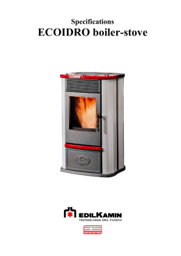
Pellet Stove
The instruction manual is an integral part of the product.
P960 - P960 F - P961
INSTRUCTIONS FOR
INSTALLATION, USE AND
MAINTENANCE
English
Dear client,
We thank you for choosing one of our products, the result of technological expertise and continued research in pursuit of a superior
product in terms of safety, reliability and features.
In this manual you will find all the information and useful advice necessary to get the most out of your appliance in total safety.
DT2010001-00
DT2010208-02
IMPORTANT INFORMATION
• This manual has been prepared by the manufacturer and constitutes an integral part
of the product, and must accompany it throughout its life. In the event of sale or
relocation of the product make sure this booklet accompanies it, since the
information contained in it is addressed to the purchaser and to anyone involved in
the installation, use and maintenance of the product.
• Read the instructions and the technical information contained in this manual
carefully, before proceeding with installation, use or any repairs.
• The observance of the instructions and technical information in this manual
guarantees the safety of the user and the product, a more efficient operation and an
increased lifespan.
• The product’s installation and use should conform to the manufacturer’s instructions
and to local bylaws.
• However, when carrying out any operation we recommend that you follow carefully
the instructions contained in this manual, and that you keep it at your disposal.
• Installation, electrical connection, checks, maintenance and repairs are operations
which must be carried out exclusively by qualified and authorised personal with
specialised knowledge of the product.
• Before installing the product read all instruction booklets relating to installation of the
cladding, the ventilation kit and any other accessories.
• Be very careful when moving any ceramic components.
• Check that the floor where the product is to be installed is exactly level.
• To help correct potential unevenness and irregularities a sheet of adhesive fibreglass
accompanies the product.
• Do not block the electrical socket; it should be close to the unit but accessible.
• Connect the pellet stove to the electricity supply only after it has been connected by
an expert to the flue system.
• The plug at the end of the power supply cable must be easily accessible after
installation.
• Use only regulation wood pellets (refer to section entitled “Fuel” ).
• Never use liquid fuels to light the stove or to relight the embers.
• Ensure that the area where the stove is installed is properly ventilated while the stove
is lit.
• In the event of technical faults the fuel supply will be interrupted. Restart the stove
only after having eliminated the cause of the fault.
• The wall where the product is to be placed should not be of wood or any other
flammable material; furthermore it is important to maintain safety distances (refer to
section entitled ‘Prevention of domestic fires’ contained in the stove’s manual for use
and maintenance).
• Do not remove the protective grille from the fuel storage tank.
• Any build-up of unused pellets in the burner left over from repeated failed ignitions
must be removed before lighting the stove.
• The operation of the stove can cause surfaces, handles, flue system and glass to
become extremely hot. Touch these parts during operation only with protective
clothing or other specialised equipment.
• Because of the build-up of heat on the glass, take care that those who are unaware
of the workings of the stove do not delay in the installation area.
• Keep children informed of safety measures to be followed when the stove is
operational and at other times.
• Creaking may be heard while the stove is in operation or cooling down.This is not to be
considered a defect, but is a consequence of thermal expansion of the component
materials.
In the event of difficulties or if you are unable to understand the instruction
manual contact your local Piazzetta dealer.
It is forbidden to place objects which are not heat-resistant on top of the
stove or within the prescribed minimum safety zone.
It is forbidden to open the door while the stove is in operation or to operate
the stove when the glass is broken.
The assembly of the cover should be undertaken by two people (follow the assembly instructions in the attached booklet).
Plans and diagrams are supplied as examples at the manufacturer’s discretion; in the pursuit of a policy of continuous development and innovation
the manufacturer may, without prior warning, make any modifications deemed appropriate.
This document is the property of Gruppo Piazzetta S.p.A.; it may not be divulged in part or in whole to third parties without written permission from
Gruppo Piazzetta S.p.A. Gruppo Piazzetta S.p.A. reserves all its statutory rights.
REFERENCE STANDARDS
DIN 18894
UNI 10344
UNI 10683
UNI 10847
UNI 7129
DIN 51731 class HP2
ÖNORM M7135
CEI EN 60335-1
CEI EN 50165÷1997
EN 1856-1-2
EN 1443
2
DT2010209-03
Solid fuel stoves and fireplaces – Pellet stoves – Requirements, testing and marking
Heating of buildings. Calculation of energy requirements
Wood-fired heat generators, Installation requirements
Single flue systems for liquid and solid fuel generators – Maintenance and control – Guidelines and procedures
Gas installations for domestic use fired by mains gas supply
Fuels
Fuels
Safety of household and similar electrical appliances.
Electrical equipment of non-electric appliances for household and similar purposes.
Chimneys – Requirements for metal chimneys – Metal liners and connecting flue pipes
Chimneys – General requirements
DT2010187-00
INDEX
Title
Page
1.0
General rules
Single flueway or chimney
Soot inspection
Chimney stack
Fresh air intake
Installation environment
Capacity load of the floor
Heating capacity
Minimum safety distances
Flueway
Connecting to a conventional chimney
Using an external flue
Prevention of domestic fires
Technical characteristics and specifications
Characteristics
Technical data
Product identification data
Plan P960
Plan P960 F
Plan P961
Electrical diagram P960 F
Electrical diagram P960 - P961
Fuel
Preparing for installation
Installation
“Multifuoco” system
Electrical connection and the room sensor connection
Installing the external thermostat
Installing the Y connector (optional)
Use
Loading the pellets
Remote control LCD
Lighting for the first time
Startup and normal operation
Control panel
Setting the language
Mode of operation (stove P960 F only)
Programming P960 F
Stove mode
Oven mode
Programming P960 - P961
Timer
Multicomfort
Modifying the transmission unit
How the “Multifuoco” system works
Safety devices
Opening the door
Humidifier (only stove P960 - P961)
Disposal of ashes
Maintenance
Cleaning the grate and the grate support
Cleaning the ash drawer
Cleaning the combustion chamber
Cleaning the combustion chamber (only P960 F)
Cleaning the smoke chamber
Cleaning the flue system
Cleaning the ceramic cladding
Cleaning the enamelled metal parts
Cleaning the glass (DAILY)
Replacing the window
Replacing the remote control battery
Cleaning the fans
When not in use
Extraordinary maintenance
Troubleshooting
Replacing the fuses
Declaration of conformity Pellet Stove P960-P960 F-P961
Declaration of conformity Transceiver unit Multicomfort
European Regulations
4
5
5
6
7
7
8
8
9
9
11
12
12
13
13
13
13
14
14
15
16
16
17
17
18
18
21
21
22
23
23
23
24
24
28
29
29
30
31
32
35
37
43
45
45
46
49
49
49
50
50
50
50
51
52
52
52
52
52
53
53
53
53
53
54
57
58
59
60
1.1
1.2
1.3
1.4
1.5
1.6
1.7
1.8
1.9
1.10
1.11
1.12
2.0
2.1
2.2
2.3
2.4
2.5
2.6
2.7
2.8
3.0
4.0
5.0
5.1
5.2
5.3
5.4
6.0
6.1
6.2
6.3
6.4
6.5
6.6
6.7
6.8
6.9
6.10
6.11
6.12
6.13
6.14
6.15
6.16
6.17
6.18
6.19
7.0
7.1
7.2
7.3
7.4
7.5
7.6
7.7
7.8
7.9
7.10
7.11
7.12
7.13
7.14
8.0
8.1
Code
DT2010216-03
English
Section
DT2010024-01
DT2010031-00
DT2010025-00
DT2010026-00
DT2010215-01
DT2010032-00
DT2010130-00
DT2010224-03
DT2010229-03
DT2010230-01
DT2010232-01
DT2010027-01
DT2010258-04
DT2010259-05
DT2010259-05
DT2010041-02
DT2030607-00
DT2030655-00
DT2030355-00
DT2030458-01
DT2030375-01
DT2010233-01
DT2010074-01
DT2010144-01
DT2010145-00
DT2010146-00
DT2010147-00
DT2010148-01
DT2010336-00
DT2010289-01
DT2010220-02
DT2010082-01
DT2010221-02
DT2010222-05
DT2010291-00
DT2010469-00
DT2010293-01
DT2010294-00
DT2010292-00
DT2010247-02
DT2010242-02
DT2010251-01
DT2010248-02
DT2010231-01
DT2010223-01
DT2010087-02
DT2010337-00
DT2010049-02
DT2010257-01
DT2010156-02
DT2010100-01
DT2010324-01
DT2010290-00
DT2010159-00
DT2010092-01
DT2010059-01
DT2010061-01
DT2010062-02
DT2010093-03
DT2010218-01
DT2010095-03
DT2010096-01
DT2010097-01
DT2010217-02
DT2010557-00
DT2010380-04
DT2010383-00
DT2010382-02
This booklet code H07003940 / DT2000161 - Rev. 02 (07/2007) comprises 60 pages.
3
English
1.0
DT2010216-02
GENERAL RULES
Ensure that the installation of your product conforms to all the indications given below.
Fig. 1
CHIMNEY STACK
SINGLE FLUEWAY
OR CHIMNEY
CONNECTION TO FLUE
SOOT INSPECTION
APERTURE
FRESH AIR INTAKE
END ELBOW WITH
INSPECTION WINDOW
MINIMUM SAFETY DISTANCES
CAPACITY LOAD
OF THE FLOOR
DT2030321-00
4
Fig. 2
English
1.1 Single flueway or chimney - Fig. 2 / 6
DT2010024-00
Every appliance must have a vertical flue pipe operating by natural
draught to discharge the combustion gases outdoors.
The flue must:
- comply with regulations in force in the place of installation of the
appliance;
- be tight to the products of combustion, waterproof, suitably insulated,
made with materials resistant to corrosion by the gases and to stress;
- be properly sized, with constant free internal section, equal to or
greater than the diameter of the flue pipe of the stove and at least 3.5
m in length (Fig. 2);
3.5
M MINIMUM
Minimo
3,5 m
- be connected to just one stove, fireplace or extraction hood (Fig. 2);
NO
MAX 45°
X
- be mainly in a vertical position with a deflection from the axis of no
more than 45° (Fig. 2);
- be at a suitable distance from combustible or flammable materials,
ensured by an air gap or suitable insulating material;
- be of uniform internal section, preferably round. Square or
rectangular sections must have rounded corners with a radius of at
least 20mm and a maximum ratio between the sides of 1.5 (Fig. 3-45). The walls must be smooth if possible and without narrowing.
Bends must be regular and without discontinuity (Fig. 6).
It is forbidden to make fixed or mobile apertures on the flue
pipe to connect appliances other than the one to which it is
already connected.
It is forbidden to pass other air ducts or service pipes inside
the flue pipe, however large it is.
DT2030049-00
Fig. 3
If the flue pipe is an incorrect size or installed other than in
compliance with the above instructions, Gruppo Piazzetta
S.p.A. cannot be held liable for malfunctioning of the product,
damage to property or injury to persons or animals.
1.2 Soot inspection - Fig. 1
DT2010031-00
- The flue must have a chamber for collecting solid matter and any
condensate located below the connection and which may be easily
inspected by means of an airtight door. (Fig.1)
Fig. 4
R
Ø
(m
in
.2
0)
Accumulo di Creosoto
Deposit
of Creosote
DT2030050-00
Fig. 5
DT2030188-00
Fig. 6
Deposit
of di
Creosote
Creosoto
Accumulo
- The bends connecting to the flue must have inspection points that
allow the system to be checked, cleaned and maintained.
R(
mi
n.
20
)
L ( 1,5 x P)
P
DT2030189-00
NO
DT2030190-00
5
Fig. 7
Fig. 8
B
B
B*
English
1.3 Chimney stack - Fig. 7 / 11
The flue must be fitted at the top with a device called a chimney stack,
designed to aid dispersion of the products of combustion in the
atmosphere.
The chimney stack must comply with the following requirements:
- it must have an internal section and shape the same as the flue;
- it must have a useful outlet section of not less than twice that of the
flue;
- the part of the flue that emerges from the roof or remains in contact
with the outside (e.g. in the case of an open loft), must be covered with
brick or tile elements and well insulated. It must be built in such a way
as to prevent the penetration of rain, snow and foreign matter into the
flue and to ensure that in the event of winds from all directions and
angle, discharge of the combustion products is assured (chimney stack
with down-draught cowl);
- any buildings or other obstacles that are higher than the chimney stack
must not be too close to the actual stack Fig.8, Fig.9;
- the chimney stack must be positioned in such a way as to ensure
adequate dispersion and dilution of the products of combustion and
outside the reflux area. The size and shape of this area differ according
to the angle of inclination of the roof and it is therefore necessary to
adopt the minimum heights shown in Fig.10,11;
** BBequivale
al
it is twice
doppio
of to di
AA
A
A
DT2030051-00
DT2030191-00
Fig. 9
6-8 m
DT2030052-00
Example: Check the slope of the roof (column α), and the anticipated
distance of the chimney stack from the axis of the ridge (column A); if
the distance is greater than “A” the height of the chimney stack may be
read in (column H); if the distance is less than “A” the chimney stack
must rise above the ridge by 0.5 metres.
Fig. 10
TETTO
PIANO
FLAT ROOF
0.50 m
0
0.50 m
m
pari 5o minore
m
or5less
over 5 m
maggiore
5m
m
m
pari5o minore
m
or5less
DT2030053-00
Fig. 11
distance maggiore
more thanA A
distanza
distance
distanza
at least
min.
ugualeAA
T
TETTO
INCLINATO
SLOPING
ROOF
0
0.50
ridge
0.50 above
m oltrethe
il colmo
REFLUX AREA
H min.
α
Pitch of the roof
α
15°
30°
45°
60°
6
Horizontal width of reflux
area from ridge axis
A
1,85 m
1,50 m
1,30 m
1,20 m
height
altezzaof
zona di
reflux
area
reflusso
Z Z
ridgecolmo
axis
asse
DT2030192-00
Minimum height of
outlet from roof
H min
1,00 m
1,30 m
2,00 m
2,60 m
Height of reflux
area
Z
0,50 m
0,80 m
1,50 m
2,10 m
The air necessary for the fire may be obtained in different ways:
- Figure 12 through an external grille direct to the room of installation;
- Figure 13 with ducting through pipes direct to the room of
installation, increasing the recommended minimum free cross
section by at least 15%;
- Figure 14 through a communicating hole from an adjacent room to
the place of installation: this system may only be used if the air flows
freely from the outside through fixed apertures;
- Figure 15 from an adjacent room to the place of installation, but only
if the air flows freely through apertures communicating with the
outside.
Fig. 12
Fig. 13
DT2030054-00
English
1.4 Fresh air intake - Fig. 12 / 15
The stove/fireplace must have the necessary air available to ensure
proper combustion.
- Make sure that the room in which the stove/fireplace is to be installed
has an air intake of at least the size indicated in the paragraph
“Technical data”.
- The fresh air intake may be protected by an external grille provided it
does not reduce the minimum section of the recommended airflow
and is in a position whereby it cannot be obstructed.
DT2030193-00
Fig. 14
1.5 Installation environment
The appliance must be installed in a location which allows safe and
convenient use as well as easy maintenance. If the product being
installed requires an electrical socket, the room must also be provided
with an earthed power supply in accordance with current regulations.
DT2030194-00
Fig. 15
Do not install a wood-burning appliance in a bedroom, bath
or shower room or in any room where another heating
system not equipped with its own air supply (fireplace, stove
etc.) has already been installed.
The room or rooms adjacent to that where the appliance is to be
installed must conform to the following requirements:
it must not be used as a car bay, a store for combustible
material, nor for any activity which carries a risk of fire;
there must be no vacuum relative to normal atmospheric
pressure as a result of the contrary draught created by a prior
installation of an open fire or of an extractor system;
DT2030195-00
do not install two stoves, a stove and a fireplace or a stove and
a wood-burning range etc. in the same location since the
draught of one device can interfere with the draught of another;
- the use of equipment adapted for cooking food with non-extractor
hoods is permissible only in rooms to be used as kitchens;
- _ equipment using gas type C is permitted (refer to regulations in
force in the place of installation);
7
English
equipment using gas type B is not permitted (refer to
regulations in force in the place of installation);
using the stove or fireplace simultaneously with shared
ventilation systems is not permitted, whether with or without
extractor fans. Similarly the use of other devices or equipment,
such as air-conditioning systems or other heating systems
which use fans to circulate air, is not permitted. These devices
can cause a pressure drop in the environment of installation
even if they are installed in adjacent, communicating rooms.
1.6 Capacity load of the floor
Check the load-bearing capacity of the floor, referring to the weight of the
product given in the paragraph “Technical data”.
If the floor does not have a suitable load-bearing capacity, adequate
countermeasures must be taken, for example, by using a sheet metal plate
to distribute the load.
1.7 Heating capacity
Check the heating capacity of the appliance by comparing the rated power
given in the paragraph “Technical data” with the power required by the
environment to be heated.
The energy requirement may be calculated approximately by multiplying
the square metres of area by the height of the ceiling; the result is then
multiplied by a coefficient, which depends on the degree of insulation of
the building, that is, on internal and external factors of the dwelling:
a) Internal factors: type of window and door frames, thickness of the
insulation and walls, type of building materials, presence of stairwells,
walls with extensive glazing, high ceilings, position of the rooms to be
heated in relation to other adjacent heated or unheated rooms, …
b) External factors: geographical position, average outdoor
temperature, exposure, wind speed, latitude, altitude, …
Example of approximate calculation of the energy requirement to
heat a fixed volume to 18/20° C:
The coefficient that is normally used is determined according to the real
conditions as they occur case by case.
- From 0.04 to 0.05 kW per cubic metre in a well insulated environment
- From 0.05 to 0.06 kW per cubic metre in a poorly insulated
environment.
3 rooms measuring 20m2 X (H ceiling) 2.7m = 162 m3 (volume)
In an environment with a good degree of insulation, an average value
(coefficient) of 0.045 kW may be taken
162 (volume) X 0.045 (kW) = 7.3 kW necessary (6300 kcal/h)
Conversion 1kW = 860 kcal/h
Consult a heating technician or engineer for a correct check
and calculation of the requirement of the environments to be
heated (see “Reference standards”).
Rated power being equal, products with the Multi-fire system
can evenly distribute heat throughout the rooms to be heated.
8
Fig. 16
English
posteriore
PareteRear
wall
B
B
STOVE
STUFA
E
In the case of flooring that is heat sensitive or inflammable the floor
should be protected with non-combustible insulating material, e.g. sheets
of steel plate, marble, tiles, etc.
Parete
laterale
Side wall
A
Parete
laterale
Side wall
1.8 Minimum safety distances - Fig. 16 / 18
First of all decide the exact position for installation of the stove.
Check the minimum safe distances from heat sensitive or inflammable
materials, from load bearing and other walls and also from wooden
elements, furniture, etc.
The minimum distances are:
A 20 cm from the wall behind the stove
B 20 cm from the side wall
C 80 cm in the heat radiation area and from the hot air fan
E
Floor protection
a pavimento
Protezione
D
C
The minimum distances are:
D 50 cm;
E 30 cm (measured from the internal corner of the door opening).
Keep any combustible product well away from the stove when it
is lit (minimum distance from the heat radiation area), for
example: wooden furniture, curtains, carpets, combustible liquids,
etc.
Zo
Heat radiation area
na
rad
ia nte
d e ll' a p e rt u r a d
Fig. 17
c
el fo
ola
re
DT2030059-01
Fig. 18
The pellet stove is not the same as other stoves. It has a forced
draught of flue gas by a fan, which keeps the firebox in a
vacuum and the entire flueway slightly pressurised. For this
reason the flue must be completely airtight and correctly
installed to ensure both trouble-free operation and user safety.
- The flueway must be made by specialised personnel or firms, as
outlined below.
- The flue must be installed in such a way as to guarantee that periodic
cleaning can be carried out without dismantling any parts
whatsoever.
- Pipes should always be sealed with silicone (not cement-based
sealants) or specially adapted gaskets/seals, which retain their
strength and elasticity at high temperatures (250°C), and should be
fixed with 3.9 mm ø self-tapping screws.
DT2030335-00
MIN 40 cm
1.9 Flueway - Fig. 19-20
MIN 40 cm
It is advisable to leave more than the indicated 20 cm free at the
side of the stove to facilitate any maintenance on the appliance.
DT2030336-00
Do not install dampers or valves that could block the passage
of flue gas.
Do not connect to a flueway into which other appliances
(boilers, extractor hoods, etc.) discharge fumes or vapours.
9
English
Pipes and maximum usable lengths
Pipes of painted aluminium-clad steel (minimum thickness
1.5mm), stainless steel (AISI 316) or enamelled steel (minimum
thickness 0.5mm) with a nominal diameter of 80 or 100 mm (for
pipes which run inside the flue maximum diameter 150 mm) can be
used.
The male-female connectors must have a minimum length of 50
mm.
The diameter of the pipes depends on the type of installation. The
stove was designed to take 80 mm diameter pipes but, as shown
in Table 1, in some cases the use of double-lined 100 mm diameter
pipes is recommended.
Fig. 19
RACCORDO
Straight
reducer
100
ø ø8080> >
øø
100
ø 100mm
ø 80mm
TABLE 1 – LENGTH PIPES
DOUBLE-WALLED
WITH 80mm Ø PIPE WITH100
mm Ø PIPE
Maximum length (with three 90° bends)
4.5 m
8m
For installations more than 1200m above sea level
Required
Maximum number of bends
3
4
Length of horizontal sections with minimum 3% gradient
2m
2m
TYPE OF INSTALLATION
Losses in pressure associated with a 90° bend can be
compared to those incurred by one metre of pipe. An
inspectable union-tee can be considered equivalent to a 90°
bend.
RACCORDO A T CON TAPPO
Tee with sealing
plug
A CHIUSURA
ERMETICA
DT2030337-00
Fig. 20
Insulating material
ISOLANTE
EXAMPLE: : if installing a section greater than 4.5m in length with
80mm diameter pipe, calculate the maximum usable length in the
following ways:
Tee
RACCORDO
- If a maximum of three 90° bends are used, the maximum length of
the section will be 4.5m
- If a maximum of two 90° bends are used and bearing in mind that a
90° bend can be replaced by one metre of pipe, the maximum length
of the section will be 4.5m+1m=5.5m
Tee
RACCORDO
AT
AT
2m
Max . 3%)
n
(mi
Direction
of
DIREZIONE
cleaning
DI PULIZIA
DIREZIONE
DI cleaning
PULIZIA
Direction of
- If a maximum of one 90° bend is used and bearing in mind that a 90°
bend can be replaced by one metre of pipe, the maximum length of
the section will be 4.5m+1m+1m=6.5m
Where 100mm diameter pipe must be used, connect it to the stove
flue outlet with a 80mm union-tee then use a 80mm 100mm adaptor
(not supplied by Piazzetta) (Fig. 19).
Union-tee
The use of this type of fitting must allow for the collection of
condensate mixed with soot, which builds up inside the pipe. It must
also permit periodic cleaning of the flue without the need to
disassemble the pipes.
This type of fitting can be bought at Piazzetta retail outlets together
with the pipes.
An example is given below of a flueway connection, which allows
complete cleaning without having to disassemble the pipes (Fig 20).
10
DIREZIONE
PULIZIA
Direction ofDIcleaning
DT2030338-00
Fig. 21
English
1.10 Connecting to a conventional chimney - Fig. 21-22
If you wish to use an existing chimney it is strongly recommended that
you have it checked by a professional chimneysweep to ensure that it
is completely airtight. The reason for this is that the smoke, because it
is slightly pressurised, can infiltrate any cracks in the flue and escape
into living spaces. If upon inspection you find that the chimney is not
completely sound, it is recommended that you insert piping made of
new material. If the existing chimney is wide enough we recommend a
pipe with a maximum diameter of 150mm. It is also recommended that
you insulate the chimney flue (Fig. 21-22).
Chimney
stack
COMIGNOLO
Tee
RACCORDO A T
Pipes and bends made by Gruppo Piazzetta S.p.A. are recommended
for connection to the flueway, since they are sized to fit the flue outlet
of the appliance.
Other pipes may be applied after adaptation and checking of the
compatibility of the coupling, taking into account that the pipes and
bends must be made in compliance with current regulations. In this
case, however, Gruppo Piazzetta S.p.A. only guarantees trouble-free
operation for parts that it manufactures and that are used according to
specifications.
CON CANNA
FUMARIA
With
damaged
flue
NON INTEGRA
INSERIMENTO
DI
Pipe
insertion
UN TUBO
ø 80 mm
Connection to the flue must respect the 40cm minimum safety
distance from heat-sensitive structural components or inflammable
materials (wood panelling, beams or ceilings, etc). (See figures 17-18).
Max ø150 mm
Inspection
SPORTELLI PER
windows
ISPEZIONE
Insulating
ISOLANTE material
- If the connector has to pass through partitions or walls of inflammable
or heat-sensitive materials, or through load-bearing walls, create:
an insulating barrier equal to or greater than 10cm around the
connector using mineral-based insulating material (rock wool,
ceramic fibre) with a nominal density greater than 80kg/m3.
DT2030339-00
Fig. 22
Closing
FLANGIAflange
DI CHIUSURA
- If the connector has to pass through non-flammable partitions or
walls, create:
an insulating barrier equal to or greater than 5cm around the
connector using mineral-based insulating material (rock wool,
ceramic fibre) with a nominal density greater than 80kg/m3.
- Check that the connection to the flueway is gas/smoke-tight, since
the appliance operates in a vacuum.
- Check that the pipe does not penetrate too far into the flueway,
thereby choking the pipe for the passage of smoke and combustion
gases.
Sealing
in stainless
FLANGIA flange
DI CHIUSURA
ERMETICA
steel
or aluminium
IN ACCIAIO
INOX O ALLUMINATO
Ensure that all installation work is carried out to professional
standards.
Fresh airPRESA
intake
with ESTERNA
D'ARIA
non-closable
grilleRICHIUDIBILE
CON GRIGLIA NON
DT2030340-00
11
English
1.11 Using an external flue - Fig. 23
An external flue can be used provided it complies with the following
requirements:
- use only insulated stainless steel pipes (double-lined) fixed to the
outside wall of the building (Fig. 23);
- there must be an inspection opening at the base of the flue to permit
periodic checks and maintenance;
- the flue must be fitted at the top with a chimney stack with downdraught cowl, also ensuring compliance with the safety distance from
the roof ridge as outlined in the section entitled
Fig. 23
d
Ensure that all installation work is carried out to professional
standards.
1.12 Prevention of domestic fires
The product must be installed and used in compliance with the
manufacturer’s instructions and European and national standards as
well as local regulations.
when a flue pipe passes through a wall or a ceiling, special
installation methods must be applied (protection, thermal
insulation, distances from heat-sensitive materials, etc.) See
the paragraph “Connection to the flueway
- It is also recommended that all elements made of combustible or
inflammable material, such as beams, wooden furniture, curtaining,
flammable liquids, etc. be kept outside the heat radiation range of the
stove and in any case at a distance of at least 1m from the heating
block.
- For other information, see the paragraph “Safety distances” and
“Connection to the flueway”.
- The flue pipe, chimney stack, chimney and fresh air intake must
always be free of obstructions, clean and checked periodically, that is,
at least twice during the seasonal period from the lighting of the stove
and during its use. When the stove has not been used for some time
it is advisable to carry out the checks mentioned above. For further
information, consult a chimneysweep.
- Only use recommended fuels (See paragraph “Fuels”).
12
FreshD'ARIA
air intake
with CON
PRESA
ESTERNA
non-closable
grille
GRIGLIA
NON RICHIUDIBILE
DT2030341-00
DT2010258-04
English
2.1 Characteristics
Fuel:
2.0 TECHNICAL CHARACTERISTICS AND SPECIFICATIONS
• Natural wood pellets
• Length: < 30mm
• Diameter: ca. 6 - 6.5 mm
• Water content: ca. 6% - 8%
2.2 Technical data
Hourly fuel consumption (max/min)
Nominal thermal power (max/min)
Efficiency
Draught when connected to chimney
Fuel tank capacity
Electrical power supply
Frequency
Frequency only for Japan
Maximum power rating
Power rating (max / min)
Exhaust outlet diameter
Fresh air intake with minimum useful section
Weight with majolica
Packing cladding
Chamber sizes (PxLxH)
Packing sizes (DxWxH)
Units
P960 F
P960 - P961
kg/h
kW
%
Pa
kg / (l)
V
Hz
Hz
W
W
cm
cm2
kg
kg
cm
cm
2,8 / 0,9
11 / 3
> 85
10-15
30 / (46)
230
50
60
350
170 / 130
Ø8
100
235
250
29x30x26
68x68x158
2,5 / 0,9
11 / 3
> 85
10-15
35 / (54)
230
50
60
350
170 / 130
Ø8
100
193
203
68x68x129
Data obtained under laboratory conditions with pellets of heat production rated at 5kwh/kg.
2.3 Product identification data
The rating plate gives the data and ratings of the appliance.
If the rating plate is missing, has been removed or tampered with,
any installation and maintenance operations are made difficult due
to lack of product identification.
In the event of damage, please ask the Piazzetta after-sales service
centre for a copy.
Product name
Serial number
DT2030624-02
13
English
2.4 Plan P960 (cm)
116
11
33
19
18
Diameter Ø 8 cm
7,7
27,5
54
63
DT2030607-00
2.5 Plan P960 F (cm)
138
11
33
19
27
18
3
7,7
27,5
Diameter Ø 8 cm
19
67 63
54
64
63
DT2030655-00
14
English
2.6 Plan P961 (cm)
116
11
19
18
7,7
27,5
33
Diameter Ø 8 cm
55
67,5
DT2030355-00
15
FLAT CABLE
English
2.7 Electrical diagram P960 F
DB 9
ANTENNA
FUEL-LOADING CHUTE
ROOM FAN
ROOM FAN
CN2
7
8
9
10
11
12
1
2
3
4
5
6
EMERGENCY DISPLAY
FUSE 5x20 500mA 250V
EXTERNAL
THERMOSTAT
FUEL-LOADING CHUTE
FUEL-LOADING CHUTE
PILOT LIGHT
PILOT LIGHT
AL.2
AL.1
N
F
N
SMOKE
SMOKE
POINTS
POINTS
FUSE 5x20 4A 250V
SERIAL
IC10
FAN 2
EMERGENCY DISPLAY
SMOKE FAN
Yellow-Green
CAPACITOR
PILOT LIGHT
FAN 1
FUSE 5x20 500mA 250V
FUSE 5x20 4A 250V
1
2
3
4
5
6
N.A. PRESSURE SWITCH
2 3
1
DB 9
Light blue
Brown
ANTENNA
SMOKE FAN
Yellow-Green
Light blue
Brown
White
White
Yellow-Green
Yellow-Green
White
Gray
Red
Red
Black
Light blue
CN2
IC10
F
N
SMOKE
SMOKE
POINTS
POINTS
7
8
9
10
11
12
Light blue
Brown
Light blue
Brown
White
White
Yellow-Green
Yellow-Green
White
Gray
Red
Red
Black
Light blue
LN
ROOM SENSOR
FUEL-LOADING CHUTE
CAPACITOR
2
90°
P
1
2 3
N.A. PRESSURE SWITCH
N.C.
2
1
180°
P
White
G
N.C.
N
L
Black
POWER - FAST ACTING FUSE 5x20 4A 250V
THERMOSTATS
Blue
Black
Brown
Black
FAN 2
FUEL-LOADING CHUTE
FUEL-LOADING CHUTE
PILOT LIGHT
PILOT LIGHT
AL.2
AL.1
N
2
Black
FAN 1
EXTERNAL
THERMOSTAT
N.C.
THERMOSTATS
DT2030458-01
SMOKE SENSOR
Blue
Red
THERMOCOUPLE
90°
P
2
1
180°
P
White
G
N.C.
N
L
Black
Black
SERIAL
OVEN SENSOR
Blue
Red
THERMOCOUPLE
LN
ROOM SENSOR
Black
Black
Blue
Black
Brown
Black
POWER - FAST ACTING FUSE 5x20 4A 250V
ROOM FAN
ROOM FAN
PILOT LIGHT
DT2030375-01
SMOKE SENSOR
16
Black
Black
White
White
Yellow-Green
White
White
Yellow-Green
2.8 Electrical diagram P960 - P961
FLAT CABLE
White
White
Yellow-Green
White
White
Yellow-Green
DT2010233-01
3.0 FUEL
Choosing other and unsuitable pellets:
- obstructs the grate and flue gas pipes
- increases fuel consumption
- reduces efficiency
- means that proper stove operation cannot be guaranteed
- causes dirt to build up on the glass
- leaves particles which have failed to burn and heavy cinders
There are various types of pellet on the market with qualities and
characteristics that vary depending on the processes they have undergone
and the type of wood used in their production.
Since the characteristics and quality of the pellet considerably affect
stove performance, efficiency and proper operation, we recommend that
you USE high-quality pellets.
The presence of moisture in the pellets increases their volume and causes
them to split which in turn causes:
- malfunction of the fuel-loading system
- inefficient combustion
Pellets should be stored in a sheltered, dry place.
Gruppo Piazzetta S.p.A has tested and programmed its stoves and can
promise optimum performance and trouble-free operation using pellets
with the following specific characteristics:
• Material:
wood
• Length:
not greater than 30mm
• Diameter:
6-6.5mm
• Net heat value:
5kWh/kg
• Moisture content:
not greater than 8%
• Residual ash:
0.34%
To ensure trouble-free operation:
DO NOT use pellets with dimensions other than those stipulated by the
manufacturer
DO NOT use pellets which are out of date or which contain loose sawdust,
resins, chemical substances, additives or caking agents.
DO NOT use damp pellets.
English
The pellet stove has been designed to burn only wood in pellet form.
The wood pellet is obtained by pressing wood sawdust left over from the
working of natural dried wood. The typical small, cylindrical form is obtained
by a process similar to wiredrawing. Thanks to lignin, a natural element which
is released during the pressing of the raw material, the pellets acquire a good
consistency and compactness without requiring treatment with additives or
caking agents.
To use good-quality pellets with other dimensions and heat-producing
properties than those recommended above, you will need to alter the
operating parameters of the stove. This “customisation” of stove settings must
be carried out at a Gruppo Piazzetta S.p.A. Service Centre or by specially
qualified personnel authorised by Gruppo Piazzetta S.p.A.
Using pellets that are out of date or not in conformity with the
manufacturer’s recommendations not only damages the stove and
jeopardises performance, but can render the guarantee null and
void and relieves the manufacturer of all liability.
Fig. 24
DT2030346-00
DT2010074-01
During operation some parts of the stove (door, handle, controls, ceramic
parts) can reach high temperatures. Take great care and all the necessary
precautions, especially in the presence of children, the elderly or disabled
and pets.
To prevent accidents or damage to the product we recommend the
following:
• unpacking and installation must be carried out by at least two people;
• every operation involving movement of the product must be carried
out with the proper tools in full compliance with current safety
regulations;
• the packaged product must be kept in the position according to the
directions shown by the diagrams and notices on the pack;
• if ropes, straps or chains are used, ensure that they are able to take
the weight of the pack and that they are in good condition;
4.0 PREPARING FOR INSTALLATION
• use slow continuous movements when moving the pack to avoid
jerking the ropes, chains, etc.;
• do not tilt the package excessively to avoid toppling;
• never stand in the vicinity of loading/unloading equipment (forklift
trucks, cranes etc).
Before installing the product make sure that you have the
correct equipment.
Unpack the product being careful not to damage or scratch it,
take the accessories pack and any pieces of polystyrene or
cardboard used to wedge moveable parts etc. out of the stove
firebox.
Keep packaging (plastic bags, polystyrene, etc.) out of reach
of children, since it could be a potential source of danger, and
dispose of according to local regulations.
17
DT2010144-01
English
5.0 INSTALLATION
Pursuant to current regulations on the safety of electrical equipment, you must contact a Piazzetta After-Sales Service Centre or a qualified
electrician for all and any work connected with installation, maintenance or servicing that involves access to electrical parts.
External pressure switch
• The stove is fitted with an external pipe tap for measuring the
pressure (vacuum) in the flue gas outlet pipe. Authorised personnel
should carry out this verification and control whilst the stove is being
installed.
5.1 Multifuoco system - Fig. 25 / 27
• Piazzetta’s technological research and development mean that
this pellet stove offers the advantages of the ‘Multifuoco’ system,
a system exclusive to and patented by Gruppo Piazzetta S.p.A., a
true innovation in the field of pellet stoves.
• The ‘Multifuoco’ system revolutionises all methods of heat
circulation currently in use in pellet stoves: the heat produced by
the furnace is circulated into the atmosphere not only from the
base of the stove itself, it can also be directed via 75mm-diameter
flexible pipes to adjoining rooms (fig 26).
This exclusive heat distribution system offers many notable
advantages: even spread of temperatures; heating adjoining
rooms.
The heat produced is propelled by a fan and distributed via the
outlet at the back of the stove.
Cladding
• Having completed assembly of the stove and installed any external
room thermostat, proceed with assembly of the stove cladding,
referring to the ceramic cladding instruction booklet provided with the
stove.
DT2010071-01
Fig. 26
DT2030162-00
Fig. 27
• The front grill is equipped with two deflectors (fig 27) to change
the direction of the heat current as it exits the front of the stove.
To deflect the heat current in the desired direction simply adjust
the angle of the deflectors (fig 30) using the lever provided (fig
29).
When the stove is lit, use the glove provided to carry out
this operation.
Fig. 25
DT2030163-00
18
DT2030213-00
it is of fundamental importance that when redirecting heat
from the rear of the stove the outlets and the Y-connector
are free of blockages to avoid overheating. In cases where
one rear outlet from the fan is to be employed, the outlet
must always be kept open.
Fig. 29
Fig. 28
English
Instructions for redirecting heat
• The fan system which expels heat into the atmosphere is
equipped with two Y-shaped devices which effectively allow the
air flow to be doubled up, directing it via a flexible pipe to the
back of the stove from where it can then be directed into
adjoining rooms.
• Below are some examples of possible installations and examples
of how to redirect the hot air in order to heat other rooms. Such
examples are intended as demonstrations; optimum performance
depends in each case on conditions in the room where the stove
is installed and in the adjoining rooms.
DT2030221-01
deflectors
DT2030222-01
Fig. 30
DT2030223-01
Fig. 31
• The examples give guidelines for redirection. Each diagram
represents only one solution of the many possible.
SOLUTION 1 - Fig. 31 - 32:
• the stove is installed in the room which is to be heated, with the heat
directed to the front only, as when the stove arrives from the factory
(fig 31). Alternatively the air can flow to the rear by connecting a
7.5cm-diameter flexible pipe to the fan (fig 32). In this scenario the
stove heats the room where it is installed by radiation only, and
heats the adjoining room by means of redirection to the rear.
DT2030216-00
Fig. 32
For the example shown in fig 32 it is necessary to use an
outlet which is permanently open.
Non-closable vents
SOLUTION 2 - Fig.33:
• The stove is installed in the room to be heated with the heat
directed to the front by one fan. A second fan directs to the rear
allowing the heating of a second room. A 7.5cm-diameter flexible
pipe with a maximum length of 6 metres is connected to the fan’s
outlet (fig 33).
For the example shown in fig 33 the vent should be permanently
open.
1m
DT2030217-00
Fig. 33
Non-closable vents
6m
DT2030218-00
19
Fig. 34
non-closable vent
6m
For the example shown in fig 34 the vent at the end of the
single redirection should be permanently open.
SOLUTION 4 - Fig. 35:
• Extending the previous solution, with the stove installed in the
room to be heated and the heat directed as in SOLUTION 3, with
the outlet from one fan doubled using a second Y connector at
the rear as shown. Use 7.5cm-diameter flexible pipe with a
maximum total length of 6 meters (fig 35).
For the example shown in fig 35, for the redirection to
function correctly and to avoid overheating, it is necessary
to use non-closable vents as shown. During operation the
vent closest to the stove should be partially open but never
closed to avoid overheating.
1m
5m
open vent
partially open vent
1m
0,5 m
Ducting through walls or floors - Fig. 36 / 39
To ensure efficient ducted heat distribution:
1) lag the pipe with insulating material to limit heat loss and
ensure a sufficiently high air temperature;
2) do not exceed the total maximum hose length of 4.5 m.
DT2030219-00
Fig. 35
0,5 m
DT2030220-00
Fig. 37
Fig. 36
Below are some examples of how the hose can be installed in walls
or floors (for better performance, lag the hose with suitable
insulating material).
DT2030168-00
Fig. 38
DT2030169-00
Fig. 39
DT2030171-00
DT2030170-00
Fig. 40
hot air outlet vent
0
R6
0
Hot air outlet vent radiation area (mm) - Fig. 40
A safety area must be ensured around the hot air outlet vent within
which there must be no flammable objects (furniture, carpets,
curtains, etc.) or heat sensitive materials (wood, plastic, etc.).
The diagram to the side shows the measurements for this safety
area, which includes 600mm from the upper edge of the vent.
600
English
SOLUTION 3 - Fig. 34:
• The stove is installed in the room to be heated with the heat
channelled in three directions. One fan propels heat to both front
and rear of the stove via the Ydevice and a length of flexible pipe
of diameter 7.5cm. The output of the second fan is directed to the
rear only via a flexible pipe of diameter 7.5cm and maximum
length 6 metres (fig 34).
600
20
600
DT2030172-00
Ensure that the electrical socket is accessible also after
installation of the stove.
Fig. 41
English
5.2 Electrical connection and the room sensor connection Fig. 41 / 43
• The stove comes with a power cable which must be connected to
a 230v/50Hz (230V/60Hz only for Japan) supply. Connection to
the rear of the stove is shown in fig. 41.
• The power rating is indicated in the paragraph “Technical data”
in this booklet.
• According to law the installation must be earthed and include a
residual current circuit breaker.
• Ensure that in its normal position the power cable does not come
into contact with any heated parts.
1
3
4
2
1
2
3
4
5
6
DT2030224-00
External socket for connection of temperature sensor
Socket for power lead
External pressure socket
Socket for inserting cable PG7 for connection of external thermostat
Connecting the temperature sensor
Connecting the power cable
Fig. 43
Fig. 42
• When installing the stove, it is necessary to connect the room
sensor (provided) in the correct socket (fig. 41). The sensor can
be positioned as shown in fig. 42-43, otherwise remove the band
and uncoil the lead and then place the sensor in a spot where a
more accurate room temperature reading can be obtained.
6
5
DT2030225-00
Fig. 44
5.3 Installing the external thermostat - Fig. 41, 44 / 47
• To connect the external thermostat use cable type 2x0.5mm2
stopped with a PG7 connector to be inserted in the appropriate
socket in the rear panel (fig 41). This operation should be
carried out by authorised personnel.
Installation can be carried out with any type of thermostat
but requires connector PG7 similar to that shown in fig 44.
To connect the thermostat to the electronic board, refer to
the electrical diagram.
• Remove the electronic board’s protective panel (fig 46).
• Stop the thermostat cable with connector PG7 and insert this in the
socket at the rear (fig 45).
• Finally connect the thermostat’s terminal to the two-pin terminal of the
electronic board (fig 47).
• Replace the electronic board’s protective panel.
DT2030226-00
Fig. 45
1
4
2
3
DT2030228-00
DT2030076-00
1
2
Thermostat
Electronic board 2-pin terminal
Fig. 46
3
4
Connector
Thermostat cable terminal
Fig. 47
electronic board’s
protective panel
DT2030227-00
DT2030077-00
21
English
5.4 Installing the Y connector (optional) - Fig. 48 / 56
• The redirection of heat to adjoining rooms is at the user’s
discretion.
• The Y-connector can be attached to either fan.
• You can choose to use only one of the fans’ outlets to heat
adjoing rooms, in which case it is more convenient to use the
right fan. Proceed as follows:
For convenience, the following assembly operations should
be carried out during the installation phase first on the left fan
(as viewed from the rear) and then on the right fan (fig 48).
1. Take off the stove’s back panel
2. Uncoil the flexible pipe from the fan’s outlet by unscrewing the
clip which holds it in place.
3. Cut around 5cm of flexible pipe (fig 49).
4. Fix the flexible pipe to the Y-connector using the clip provided
(fig 50).
5. Fix the Y-connector to the fan’s outlet using the screws
provided (fig 51). (for the left fan see fig 53)
6. Attach the second flexible pipe to the Y connector using the clip
provided (fig 52).
7. Repeat stages 2 - 6 for the right fan.
8. Take off the sub-section of the back panel (fig 55).
9. Replace the back panel.
10. Move the stove closer to the wall (fig 54) and, using the clips
provided, fix the two flexible pipes to the pipes in the wall (fig
56).
11. Place the stove in the desired location, respecting the minimum
safety distances (see section 1.8).
Fig. 48
Fig. 49
left fan
right fan
DT2030229-00
DT2030230-00
Fig. 50
DT2030175-00
Fig. 51
Fig. 52
DT2030232-00
Fig. 53
DT2030178-00
Fig. 54
tightening screws
DT2030231-00
Fig. 55
Fig. 56
DT2030233-00
22
DT2030180-00
DT2030181-00
DT2010336-00
6.0 USE
Fig. 51
Fig. 52
English
• Do not use the stove as a cooking appliance.
• Ensure that the room in which the stove is installed is sufficiently well
ventilated (fresh air intake).
• Ensure that all joints in the flue are hermetically sealed using a
silicone- (not cement-) based sealant which is resistant to
temperatures of up to 250ºC and which shows no sign of
deterioration.
• Check (or have checked) regularly that the flue is clean.
• Under no circumstances use fuels other than pellets.
• Remove any deposits of unused pellets left by failed ignitions before
restarting the stove.
Keep any inflammable object well away from the stove while
it is in use (MINIMUM 80 cm from the front panel).
While in use the door must remain closed and the glass must
be present and intact.
The removal of the protective grille inside the pellet hopper
is strictly prohibited.
If replenishing with pellets while the stove is lit, ensure that
the bag does not come into contact with any hot surfaces
DT2010035-01
6.1 Loading the pellets - Fig. 51 - 52
• To load the pellets into the hopper it is advisable to tear off the edge
of the sack and empty the sack directly into the hopper. This makes
filling easier and avoids pouring pellets on top of the stove.
Do leave leftover pellets on top of the stove – they could
catch fire!
DT2030459-00
DT2030460-00
Fig. 53
17
15
19
20
18
13
16
2
14
!
1
1 2 3 47 5 6
4
6
3
7
6.2 Remote control - Fig. 53
• The pellet stove comes equipped with an LCD-display remote control
and radio transmitter which allow you to operate its various functions.
The remote’s range can be affected by other devices which
operate on a continuous radio frequency of 433.92 MHz , for
example radio headphones, toys, wireless mouses etc.
The remote has a range of around seven metres in conditions
where there is no interference from other sources.
• When pressing the keys to select the various functions wait for a
signal from the stove that the selection has registered before
selecting further functions. Or if you are in an adjoining room wait for
confirmation on the remote’s display. If the stove is not receiving
signals from the remote try bringing the remote closer to the stove.
Below are listed the various functions of the remote control’s keys.
5
11
8
9
10
MENU
ESC
SET
OPT
12
DT2030325-00
23
English
NUMBER
1
KEY / DISPLAY
Key ON/OFF
2
Key STAND-BY
3
Key POWER
4
Key FAN SPEED
5
Key SELECT
6
Key TEMPERATURE
7
Key TIMER
8
Key MENU
9
10
11
Key SET
Key MENU SELECTION
Key ESC
DESCRIPTION
Allows you to start up or shut down the stove.
Pressing the stand-by key and holding it down (for around 5 seconds) until KEYPAD BLOCKED
appears on the display will disable the keypad. To re-enable the keypad press the stand-by key
and hold it down (for around 8 seconds) until KEYPAD UNBLOCKED appears on the display.
Allows you to select the power setting. With the SELECT key you can choose between the four
available settings, P1-P2-P3-P4-P5.
Allows you to choose the speed setting on the Multifuoco fan. With the SELECT key you can choose
between the three available settings, 1-2-3-4.
• power level - having previously pressed the POWER key
Allows you to choose:
• fan speed - having previously pressed the FAN SPEED key
• temperature - having previously selected the TEMPERATURE key
Allows you to set the room temperature. The SELECT key will allow you to choose the desired
temperature between 7°C and 30°C.
Displays the current date and time.
Allows:
• access to the programming menu
• return to the initial display
Confirm MENU selected
Scrolls through the programming MENU
Returns to previous menu
12
Key OPT
Displays the MULTICOMFORT temperatures. The dash before the temperature shows which sensor
is giving the temperature reading.
13
14
Display
Display POWER
15
Display MULTIFUOCO
16
Display DAYS OF THE WEEK
17
18
19
20
Display RADIO SIGNAL EMISSION
Display TIMER
Display SAFETY
Display FLAT BATTERY
Shows on three lines the function settings, the current time and the temperature.
Shows the power setting selected, P1-P2-P3-P4-P5.
Shows the Multifuoco setting selected, 1-2-3-4.
On the P961 the two lines of squares to the left and to the right show respectively the left or right
fan.
Shows the day of the week, 1 Monday, 2 Tuesday, 3 Wednesday, 4 Thursday, 5 Friday, 6 Saturday,
7 Sunday.
Active if the remote is receiving data from the stove
Shows that the timer is engaged
Symbol appears when the safety system is activated
Shows that the battery is flat
6.3 Lighting for the first time
• Before lighting the stove check that the grate is pushed back towards
the baffle plate.
• When lighting the stove for the first time or when it has not been used
for some time, it is advisable not to operate the stove at full power
immediately. For the first few days, operation at medium power is
recommended to allow all materials and mechanical parts to settle.
Upon first ignition certain odours may be given off due to the
evaporation of paint or grease. To alleviate the problem just air the
room. Do not remain in the room when there are odours, as the fumes
may be harmful to people or pets.
• When the pellet hopper is loaded for the first time the loading auger
has to fill up; during this period the pellets will not be fed into the
firebox.
6.4 Startup and normal operation - Fig. 54
• Before proceeding with lighting the stove:
Fig. 60
!
!
Ensure that the hearth door is well closed.
• Check that the pellet hopper is full or at least contains enough pellets for
the stove to run for the desired period.
• When the stove is connected to the power supply but is not yet lit, the
display will show the readout OFF and in the lower half the current time,
the measured temperature and the previously set power and fan settings.
24
OF F
09 : 53
1
20
.c
Action
Function
English
STARTUP
Display
A cycle starts with three phases which take
the stove into the normal operating mode:
!
!
• CONTROL first 20 seconds
The extractor fan activates for a few seconds.
CON T ROL
.
1 2 : 00
2 2c
1
Hold the on/off key
down for several
seconds
• START PHASE I
The fuel-loading chute is activated and starts to
feed pellets into the burner (the LED on the
display lights up at fixed time intervals).
The pilot light ignites (the LED on the display
lights up).
The extractor fan starts up.
!
!
S T AR T
PHASE I
.
1 2 : 00 22c
1
• START PHASE II
If the lighter has triggered the combustion process, the
fuel-loading auger slows down to allow a period of
stabilisation and correct combustion of the pellets in the
subsequent normal operating mode.
If during the startup phase the sensor on the flue gas
outlet shows a rise in temperature (sign that the
combustion process is underway), the stove is
considered to be lit and goes into the normal operating
mode.
If during the startup phase the sensor on the flue gas
outlet does NOT show a rise in temperature (sign that the
combustion process is not underway), the stove should
be considered off; a new ignition cycle will begin
automatically and the three preceding phases will be
repeated in succession.
!
!
S T AR T
P H A S E II
.
1 2 : 00 22c
1
DT2040051-02
FAILED IGNITION
Action
Function
A second failed ignition is indicated on the display
in the STOVE STATUS function by the readout “NO
LIT” as well as the smoke sensor temperature,
see “PROGRAMMING” paragraph. In addition a
beep is emitted once every 5 seconds. This safety
device is activated if the pellets do not ignite, if the
pellet hopper is empty or if the temperature fails
to rise.
Display
!
!
NO
L I T
1
DT2040056-01
MENU
25
English
FAILED IGNITION: WHAT TO DO
Action
Function
Shut the stove down
pressing
the
by
ON/OFF key down for
several seconds.
Display
!
• the alarm should stop;
• check the cause of the failed ignition. Always
remove any fuel from the grate before starting a
new ignition process.
!
C L EAN I NG
BRAZ I ER
.
1 2 : 00 22c
1
Restart the stove by
pressing the ON/OFF
key.
• Repeat the ignition process as described above.
If the appliance does not ignite properly the main cause could be either insufficient maintenance (consequently refer
to the “Maintenance” paragraph) or the poor quality of the pellets (refer to the “Fuel” paragraph). It is therefore
recommended to check these conditions before attempting to relight the appliance.
DT2040057-02
NORMAL OPERATION
Action
Function
Display
Once the startup cycle has been completed
successfully the stove stabilises in the normal
operating mode.
!
The power, fan speed and room temperature may
be adjusted during normal operation. To the side is
an example of the INITIAL DISPLAY in normal
operation.
!
LEVEL
P2
.
1 2 : 00 22c
1
Press the
POWER
key
!
POWER
To adjust the power, press the POWER key and
select the desired setting by pressing the SELECT
key. After the desired setting has been selected
the remote control returns to the INITIAL
DISPLAY.
and to select
MENU
!
SE T
POWER
P2
1
SET
Press the FAN
key
ESC
MENU
MENU
SET
ESC
and to select
OPT
SET
ESC
OPT
MENU
SET
MENU
ESC
SET
26
OPT
OPT
ESC
To adjust the Multifuoco setting, press the FAN key and
select the desired Multifuoco setting using the SELECT
key. On the P961 stove it is possible to adjust the two
fans separately if SEPARATE FANS has been set in the fan
mode menu. After having pressed the FAN key once
(VENT 1 appears on the display) and selected the desired
Multifuoco setting for the left fan, press the FAN key
again (VENT 2 appears on the display) and select the
desired Multifuoco setting for the right fan. After the
desired Multifuoco setting has been selected the remote
control returns to the INITIAL DISPLAY. To maximise the
potential of the Multifuoco function read the paragraphs
MULTIFUOCO AND MULTICONFORT OPERATION.
!
!
SE T
VENT - 1
1
1
Function
Press the
TEMPERATURE
key
and select
MENU
MENU
Display
To adjust the temperature setting, press the
TEMPERATURE key and select the desired
temperature by using the SELECT key (range 7°C
to 30°C). When the desired temperature has been
reached the readout OK appears in the initial
display and the stove operates at minimum power
even if the display shows the originally set power
level. The temperature can be read by the remote
control, by the stove itself or by an external
thermostat. To choose whether the remote or the
stove will read the temperature see the section
entitled
PROGRAMMING,
paragraph
MULTICONFORT. If using an external thermostat
the readout "ton" appears in the initial display
and the readings from the stove and the remote
control are cut out.
English
Action
!
!
SE T T EMP
ROOM
.
26c
1
SET
SET
ESC
ESC
OPT
OPT
During normal operation the automatic grate
cleaning function activates periodically, the
frequency varying according to the settings preprogrammed by Gruppo Piazzetta personnel. This
operation removes ash deposits and other
buildups, which would otherwise prevent correct
stove operation. The readout "PUL" appears in
STOVE STATUS along with the flue gas
temperature. See the Programming section.
!
!
C L EAN I NG
BRAZ I ER
.
1 2 : 0 0 2 6c
1
DT2040062-01
EXTERNAL THERMOSTAT
Action
Function
Display
Stove operation can be regulated by any kind of
external room thermostat connected to the
electronic board.
To connect the thermostat, see paragrap
“Installing the external room thermostat”.
Operation of the external thermostat depends on
the stove temperature setting.
- If the set stove temperature is less than the
room temperature, the external thermostat
prevails. (It is advisable to set a minimum value
of 7°C for the stove).
- If the set stove temperature is more than the
room temperature, the internal stove thermostat
prevails. The external thermostat is disabled.
The room sensor must be connected. If
the room sensor is not connected the
appliance does not modulate the power
and operates to user settings.
DT2040059-02
27
English
SHUTDOWN
Action
Function
Display
Hold the ON/OFF key
down for several
seconds
Fuel loading stops, while the cooling fan and the
extractor fan continue to operate for approx.
another 10 minutes until the stove has cooled.
The readout "PUL" appears in STOVE STATUS
along with the flue gas temperature. See the
section on programming.
!
!
C L EAN I NG
BRAZ I ER
.
1 2 : 00 22c
1
Never unplug the stove from the power supply at this stage as this could cause internal problems and compromise
subsequent ignition operations.
DT2040060-01
INTERRUPTION OF POWER SUPPLY
Action
Function
Display
In the event of a brief interruption of the electrical
current while the stove is in operation, the stove
will restart automatically.
• The grate cleaning phase activates.
• The fan operates at full speed to allow the stove
to cool.
• The readout "PUL" appears in the STOVE STATUS
mode. See the section on programming.
• The automatic stove restart cycle begins
(functions detailed in ‘STARTUP’ activate
automatically).
• Once the ignition cycle has been completed the
stove operates normally at power level 2.
• The stove will continue operating normally at
power level 2.
6.5 Control panel - Fig. 55
The stove is fitted with a digital control panel to operate stove functions
when the LCD remote control is unavailable. The various functions of
the control panel are listed below.
Fig. 61
!
!
C L EAN I NG
.
1 2 : 00 22c
1
DT2040061-01
2
1
3
8
7
4
3
2
6
5
1
DT2030332-00
NUMBER MENU
KEY / DISPLAY
1
Key ON/OFF
2
Led ON/OFF
SET
3
Key INCREASE POWER
4
5
6
7
8
28
DESCRIPTION
Allows you to manually start up or shut down the product.
The LED being lit indicates that the stove is lit.
Allows you to increase the power setting. You can choose between the two available settings, P1-P3.
The Multifuoco fan has a default setting for each of the two power settings.
Led INCREASE POWER
The LED lights up when the power-increase key is pressed and indicates that the increase has registered.
Allows you to decrease the power setting. You can choose between the two available settings, P1-P3.
Key DECREASE POWER
ESC
The Multifuoco fan has a default setting for each of the two power settings.
The LED lights up when the power-decrease key is pressed and indicates that the decrease has
Led DECREASE POWER
registered.
The led lighting up indicates that the safety system has been activated. After 60 seconds the alarm
OPT
signal will sound. In the event of the safety system being activated proceed as follows:
• Turn off the stove by holding the ON/OFF key down for several seconds.
Led SAFETY
• The alarm signal will stop.
• Wait until you are sure that combustion of any pellets left in the burner has ceased.
• Wait for the stove to cool, then check for and remove whatever has activated the safety system.
Finally, after having cleaned the burner, restart the stove by pressing the ON/OFF key.
Led RADIO SIGNAL EMISSION The led lights up if the stove receives data from the remote control.
2. press the “MENU” key;
3. scroll with the SELECT key “
displayed;
!
English
6.6 Setting the language
1. open the flap on the remote control;
SE L EZ I ONE
L I NGUA
“ until “SELECT LANGUAGE” is
MENU
SET
ESC
OPT
!
4. press the “SET” key;
5. scroll with the SELECT key “
displayed, e.g. “ENGLISH”;
L I NGUA
ENGL I SH
“ until the required language is
MENU
SET
ESC
OPT
6. press the “SET” key to enter and confirm the required language.
!
FUNC T I ON
ENABL ED
6.7 Mode of operation (stove P960 F only)
The “MENU” key can be used to set two different modes of operation of the
stove.
STOVE mode
The stove is set for heating operation. The STOVE mode allows activation
of the Multifuoco® system or Multicomfort® system (See paragraph,
Programming P961).
OVEN mode
The OVEN mode setting is to be found only in the stove with oven (P960 F)
and activates the ideal system for cooking food, which offers the possibility
of setting the temperature and cooking time. See the paragraphs
concerned with OVEN mode (Programming P960 F) for the settings.
In this mode all the set systems of Multifuoco® heating and the timer
thermostat are automatically disabled. The stove automatically controls the
power and the fan speed is at minimum.
!
S T OVE
!
OVEN
To pass from the STOVE MODE (with medium-high power) to the
OVEN MODE it is necessary to wait for the oven temperature to
drop to the set cooking temperature. The oven may only be used
after the buzzer has sounded and the writing “OK” has
appeared on the display.
It is advisable to pass to the OVEN MODE when the stove is in
the STOVE MODE at medium-low power.
If automatic lighting through the timer thermostat has been set,
the stove must be turned off in the STOVE mode, otherwise
automatic lighting will be impossible.
29
English
6.8 Programming P960 F
The remote control can be used to select the following functions from the main menu:
SET
• SELECT LANGUAGE
ENGLISH
ITALIANO
DEUTSCH
FRANCAIS
SET
• STOVE
SET
• SET CLOCK
1-DAY MONDAY
2-DAY TUESDAY
3-DAY WEDNESDAY
Remote Control
4-DAY THURSDAY
5-DAY FRIDAY
MENU
ESC
SET
OPT
6-DAY SATURDAY
7-DAY SUNDAY
SET
• SET TIMER
PROGRAM DAY
PROGRAM WEEK
MENU
PROGRAM WEEK-END
SET
• MODE FANS
FANS NORMAL
FANS SEPARATE
SET
• MULTICOMFORT
SELECT RRC
SELECT STOVE
SET
• MENU PARAMETER
• ENABLE BEEP
• STATE STOVE
• ESC (Exit)
SETTINGS FACTDRY
> key access
DATA BANK
> key access
SETTINGS LOAD
> key access
SETTINGS SMOKE EXIT
> key access
MULTIFUOCO V1
> key access
MULTIFUOCO V2
> key access
SET
• OVEN
• SELECT OVEN
• TEMP OVEN
• TIMER OVEN
• SELECT TIMER
• ESC (Exit)
These functions are activated by opening the front flap and pressing the following keys:
• the MENU key is used to access the main menu and return to the initial display at any time during programming to alter data that has been input
incorrectly.
• the MENU SELECTION key is used to scroll through the main menu and the submenus.
• the SET key is used to confirm a MENU or a selection.
• the ESC is used to return to the previous menu display at any time during programming to alter data that has been input incorrectly.
30
English
6.9 Stove Mode
In this STOVE MODE the stove is set for heating operation, thereby
activating all the functions of the Multifuoco® or Multicomfort® system
(See paragraph “Programming P960-P961”).
!
OVEN
MENU
MENU
SET
How to set the stove mode:
1) open the flap of the remote control;
2) press the MENU key;
3)
4)
5)
6)
MENU
set the mode OVEN by pressing the
confirm using the SET key;
set SELECT OVEN;
confirm again using the SET key
MENU
SET
ESC
ESC
OPT
OPT
or
key;
!
SET
SELEC T
OVEN
SET
ESC
ESC
OPT
OPT
7) using the key or , set “oFF” to deactivate the oven mode;
8) confirm using the SET key (STOVE ENABLED);
9) press the ESC key twice to exit from the menu.
oFF
!
S T OVE
ENABL ED
31
English
6.10 Oven Mode
!
In the OVEN mode the stove is set for cooking operations.
OVEN
How to set the oven mode:
MENU
1) open the flap of the remote control;
MENU
SET
SET
ESC
2) press the MENU key;
ESC
OPT
OPT
3) set the OVEN mode by pressing the key
!
or
;
SELEC T
OVEN
4) confirm using the SET key;
MENU
5) set SELECT OVEN;
MENU
SET
SET
ESC
6) confirm again using the SET key;
ESC
OPT
!
OPT
7) with the key
or
SELEC T
OVEN
, set on to activate the oven mode;
8) confirm using the SET key (OVEN ENABLED);
ON
9) press the ESC key twice to exit from the menu.
Press the OPT key to display the set functions.
!
OVEN
ENABL ED
The required function must be enabled each time by setting
it to “on”, otherwise it will be memorized only but not taken
into consideration.
In this mode the oven temperature TEMP OVEN is set. A buzzer sounds
when the temperature has been reached and the writing “OK” appears
on the display.
Once the required real oven temperature has been reached, an TIMER
OVEN automatically activates with the required cooking time; when this
set time has elapsed the writing “GOOD” appears on the display and a
buzzer sounds.
The oven temperature TEMP OVEN or the cooking time OVEN TIMER
may be reset at a later time; just enter the MENU parameters again and
use the key
or to go to the item to be changed (see paragraph
“Programming P960 F”).
MENU
MENU
SET
SET
ESC
ESC
OPT
!
PROCEDURE
OVEN
F
OPT
A variation in colour tone of the stove is a natural
characteristic of steel subjected to sharp temperature
changes. This does not affect the quality of the product.
32
!
PROCEDURE
OVEN OK
FT
GOOD
Function
Action
English
HOW TO SET THE OVEN TEMPERATURE
Display
Open the remote control flap.
Press the MENU key.
!
OVEN
MENU
SET
ESC
OPT
Setting the OVEN
mode
Use the key
to scroll the settings until OVEN.
Confirm using the SET key.
!
SELEC T
OVEN
MENU
SET
ESC
!
OPT
Setting the OVEN
TEMP mode
T EMP
OVEN
Use the key
to scroll the settings until OVEN
TEMP.
Confirm using the SET key.
MENU
MENU
SET
SET
ESC
ESC
OPT
OPT
!
Use the key
or
to set the required
temperature anywhere between a minimum of
150°C and a maximum of 260°C.
Confirm using the SET key.
Setting the
temperature
T EMP
OVEN
.
200c
The appliance now automatically passes to the OVEN TIMER mode. To proceed with settings, see the
table “HOW TO SET THE OVEN TIMER”.
!
Exiting
MENU
from
the
Press the ESC key twice.
The display returns to the display page
OVEN MODE.
PROCEDURE
OVEN
F
DT2040074-00
33
English
HOW TO SET THE OVEN TIMER
Function
Action
Display
Open the remote control flap. Press the MENU key.
!
OVEN
MENU
SET
ESC
OPT
Setting the OVEN
mode
Use the key
to scroll the settings until OVEN.
Confirm using the SET key.
!
SELEC T
OVEN
MENU
SET
ESC
!
OPT
Setting the OVEN
TIMER mode
T I MER
OVEN
Use the key
to scroll the settings until OVEN
TIMER.
Confirm using the SET key.
MENU
MENU
SET
SET
ESC
ESC
OPT
!
OPT
Setting
temperature
the
T I MER
OVEN
Use the key
or
to set the required cooking
time anywhere between a minimum of 1 minute
and a maximum of 180 minutes.
Confirm using the SET key.
MENU
MENU
SET
1
30
SET
ESC
ESC
OPT
!
OPT
Activating the timer
SELEC T
T I MER
Use the key
or
to activate with on or
deactivate with oFF the oven timer.
Confirm using the SET key.
ON
!
T I MER
ENABL ED
Exiting from the
MENU
Press the ESC key twice.
The display returns to the display page OVEN
MODE.
!
PROCEDURE
OVEN
Ft
34
DT2040075-00
English
6.11 Programming P960 - P961
The remote control can be used to select the following functions from the main MENU:
SET
• SELECT LANGUAGE
ENGLISH
ITALIANO
DEUTSCH
FRANCAIS
SET
• SET CLOCK
Remote Control
1-DAY MONDAY
2-DAY TUESDAY
MENU
ESC
3-DAY WEDNESDAY
SET
OPT
4-DAY THURSDAY
5-DAY FRIDAY
6-DAY SATURDAY
7-DAY SUNDAY
SET
• SET TIMER
PROGRAM DAY
MENU
PROGRAM WEEK
PROGRAM WEEK-END
SET
• MODE FANS
FANS NORMAL
FANS SEPARATE
• MULTICOMFORT
SET
SELECT RRC
SELECT STOVE
SET
• MENU PARAMETER
• ENABLE BEEP
• STATE STOVE
• ESC (Exit)
SETTINGS FACTDRY
> key access
DATA BANK
> key access
SETTINGS LOAD
> key access
SETTINGS SMOKE EXIT
> key access
MULTIFUOCO V1
> key access
MULTIFUOCO V2
> key access
These functions are activated by opening the front flap and pressing the following keys:
• the MENU key is used to access the main menu and return to the initial display at any time during programming to alter data that has been input
incorrectly.
• the MENU SELECT key is used to scroll through the main menu and the submenus.
• the SET key is used to confirm a MENU or a selection.
• the ESC is used to return to the previous menu display at any time during programming to alter data that has been input incorrectly.
35
English
SET CLOCK (current day/time)
Function
Action
Display
!
Set the day
SE T
CLOCK
Press the MENU key, select the SET CLOCK menu
using the SELECT MENU key, then confirm by
pressing the SET key.
MENU
SET
ESC
OPT
!
!
Confirm setting and
move to next section.
DAY
MONDAY
Press the SELECT MENU key and set the “day”.
Confirm by pressing the SET key.
MENU
SET
ESC
OPT
1
!
Set the hour.
Press the SELECT MENU
key and set the
current “hour”. Confirm by pressing the SET key.
MENU
SET
HOURS
CLOCK
ESC
OPT
12:
!
Set the minutes
Press the SELECT MENU
key and set the
“minutes”. Confirm by pressing the SET key.
After confirmation the initial display will reappear.
MENU
SET
ESC
M I NU T ES
CLOCK
OPT
:01
36
DT2040064-01
For example:
Cycle 1: from 6am until 9am
Cycle 2: from 8.30pm until 11pm
• In the DAILY programme the two timetable bands once established can be activated or deactivated for all the days of the week.
For example: if you want the stove to operate from 6am to 9am every day
• In the WEEKLY programme the two timetable bands once established can be activated or deactivated for each day.
For example: if you want the stove to operate from 6am to 9am on Monday, Tuesday, but not on Wednesday, and so on.
• In the WEEKEND programme the two timetable bands once established can be activated or deactivated for Friday, Saturday and
Sunday.
For example: if you want the stove to operate from 6am to 9am on Friday, Saturday, but not on Sunday.
This kind of timer allows you to have three programmes (DAILY, WEEKLY and WEEKEND) stored permanently. The programmes can be
activated or deactivated using the SET TIMER menu. It is advisable to have only one programme active at a time to avoid overlapping.
WHEN USING THE TIMER FOR THE FIRST TIME, SET THE CLOCK WITH THE CURRENT DAY, HOUR AND MINUTES, as with a
new watch. To set the actual time, see the table SETTING THE CLOCK. This setting will only be necessary the first time
of activating the clock.
PROGRAM DAY - 1st operating cycle
Function
Action
Display
!
Select SET CHRONO
menu
Press the MENU key. Using the SELECT MENU
key select the SET CHRONO menu and confirm by
pressing the SET key.
MENU
SET
ESC
SE T
CHRONO
OPT
!
Select day
programme
Using the SELECT MENU
key select the dayprogramme PROGRAM DAY menu and confirm by
pressing the SET key.
MENU
SET
ESC
PROGRAM
DAY
OPT
Press the SELECT MENU
key and select oN to
enable the day programme or oFF to disable the
day programme. Confirm by pressing the SET key.
If you have disabled the programme by selecting
oFF and do not wish to carry out further
programming, press the ESC (EXIT) key to return to
the previous menu or the MENU key to return to the
initial display.
MENU
!
SET
ESC
OPT
Enable or disable
day programme
ENABL E
DAY
OFF
37
English
6.12 Timer
The timer allows the user to programme the stove to start up and shut down automatically without any manual intervention.
Daily, weekly and weekend programmes can be selected with a maximum of two operating cycles in two separate timetable bands.
English
Function
Action
Display
!
Set startup time for
1st operating cycle.
Press SELECT MENU
to set the startup time,
advancing in ten-minute jumps (for example, you
want the stove to start up at 06:00). Confirm by
pressing the SET key.
MENU
SET
ESC
OPT
S T AR T
D
PROGRAM 1
06 : 00
!
Press SELECT MENU
to set the shutdown time,
advancing in ten-minute jumps (for example, you
want the stove to shut down at 09:00). Confirm by
pressing the SET key.
MENU
SET
ESC
OPT
S T OP
D
PROGRAM 1
09 : 00
Set shutdown time
for 1st operating
cycle.
!
In this stage a shutdown time need not be set.
Press SELECT MENU , set the readout oFF and
confirm by pressing the SET key.
MENU
S T OP
D
PROGRAM 1
SET
ESC
OPT
OFF
!
Set desired power for
first operating cycle.
Press SELECT MENU
to set the desired power
(for example you want power setting 1). Confirm
by pressing the SET key.
MENU
SET
ESC
SE T
POWER
D
1
OPT
01
Press SELECT MENU
to set the desired room
temperature (for example, you want a room
temperature of 25°C). Confirm by pressing the
SET key. When the desired temperature has been
reached the stove automatically reverts to power
setting P1 and the temperature can be read on the
remote or on the stove - see Multicomfort menu.
!
MENU
SET
Set
room
temperature for first
operating cycle.
ESC
OPT
SE T T EMP
ROOM
.
2 5c
!
Set
desired
Multifuoco fan speed
for first operating
cycle.
Press SELECT MENU
to set the desired fan
speed (for example, you want fan speed setting 1).
Confirm by pressing the SET key. Confirm by
pressing the SET key. When programming the
timer on the P960-P960F-P961 stove it is not
possible to set separate fan speeds.
MENU
SET
ESC
OPT
SET
VENT - 1
D
01
!
After having programmed the first operating cycle you may, if you wish,
proceed with programming the second operating cycle by going through
the settings in the order as described above. The number 2 appears on
the display to indicate the second operating cycle.
S T AR T
D
PROGRAM 2
06 : 00
38
DT2040067-01
Function
Action
English
PROGRAM WEEK
Display
!
Select set chrono
menu
SE T
CHRONO
Press the MENU key. Using the SELECT MENU
key select the SET CHRONO menu and confirm by
pressing the SET key.
MENU
SET
ESC
OPT
!
Select week
programme
Using the SELECT MENU
key select the weekprogramme PROGRAM WEEK menu and confirm
by pressing the SET key.
MENU
SET
ESC
PROGRAM
WEEK
OPT
Press the SELECT MENU
key and select oN to
enable the week programme or oFF to disable the
week programme. Confirm by pressing the SET
key. If you have disabled the programme by
selecting oFF and do not wish to carry out further
programming, press the ESC (EXIT) key to return
to the previous menu or the MENU key to return to
the initial display.
!
MENU
SET
ESC
OPT
Enable or disable the
week programme
ENABL E
WEEK
OFF
!
Set startup time for
1st operating cycle.
Press SELECT MENU
to set the startup time,
advancing in ten-minute jumps (for example, you
want the stove to start up at 06:00). Confirm by
pressing the SET key.
MENU
SET
ESC
OPT
S T AR T
W
PROGRAM 1
06 : 00
!
Press SELECT MENU
to set the shutdown time,
advancing in ten-minute jumps (for example, you
want the stove to shut down at 09:00). Confirm by
pressing the SET key.
MENU
SET
ESC
OPT
S T OP
W
PROGRAM 1
09 : 00
Set shutdown time
for 1st operating
cycle.
!
In this stage a shutdown time need not be set.
Press SELECT MENU
, set the readout oFF and
confirm by pressing the SET key.
MENU
S T OP
W
PROGRAM 1
SET
ESC
OPT
oFF
Activate
or
deactivate the first
operating cycle on
individual days of the
week.
Press the top part of the SELECT MENU
key to select the
day of the week, then press the bottom part of the SELECT
MENU key to select oN to activate the first operating cycle
on the chosen day or oFF to deactivate the first operating cycle
on the chosen day. Active days will be shown on the DAYS OF
THE WEEK display by the digits 1 MO - 2 Lu - 3 UE - 4 LH - 5
Fr - 6 SA - 7 Su. Confirm by pressing the SET key.
!
MENU
SET
ESC
OPT
MENU
SET
ESC
!
DAYS
L IT
W
1
OPT
Su
oN
7
39
English
Function
Action
Display
!
Set desired power for
first operating cycle.
to set the desired power
Press SELECT MENU
(for example you want power setting 1). Confirm
by pressing the SET key.
MENU
SET
ESC
SE T
POWER
W
1
OPT
01
Press SELECT MENU
to set the desired room
temperature (for example, you want a room
temperature of 25°C). Confirm by pressing the
SET key. When the desired temperature has been
reached the stove automatically reverts to power
setting P1 and the temperature can be read on the
remote or on the stove - see Multiconfort menu.
!
MENU
SET
Set
room
temperature for first
operating cycle.
ESC
OPT
SE T T EMP
ROOM
.
2 5c
!
Set
desired
Multifuoco fan speed
for first operating
cycle.
Press SELECT MENU
to set the desired fan
speed (for example, you want fan speed setting 1).
Confirm by pressing the SET key. When
programming the timer on the P960-P960F-P961
stove it is not possible to set separate fan speeds.
MENU
SET
ESC
OPT
SE T
VENT - 1
W
01
!
After having programmed the first operating cycle you may, if you wish,
proceed with programming the second operating cycle by going through
the settings in the order as described above. The number 2 appears on
the display to indicate the second operating cycle.
S T AR T
W
PROGRAM 2
06 : 00
DT2040068-01
WEEKEND PROGRAMME
Function
Action
Display
!
Select set chrono
menu
SE T
CHRONO
Press the MENU key. Using the SELECT MENU
key select the SET CHRONO menu and confirm by
pressing the SET key.
MENU
SET
ESC
OPT
!
Select
weekendprogramme
Using the SELECT MENU
key select the
PROGRAM WEEK-END weekend-programme
menu and confirm by pressing the SET key.
MENU
SET
ESC
OPT
40
PROGRAM
WEEK- END
Action
Display
Enable or disable
weekend programme
key and select on to
Press the SELECT MENU
enable the weekend programme or oFF to disable
the weekend programme. Confirm by pressing the
SET key. If you have disabled the programme by
selecting oFF and do not wish to carry out further
programming, press the ESC key to return to the
previous menu or the MENU key to return to the
initial display.
English
Function
!
MENU
SET
ESC
OPT
ENABL E
WEEK- END
OFF
!
Set startup time for
1st operating cycle.
Press SELECT MENU
to set the startup time,
advancing in ten-minute jumps (for example, you
want the stove to start up at 06:00). Confirm by
pressing the SET key.
MENU
SET
ESC
OPT
S T ART
WE
PROGRAM 1
06 : 00
!
Press SELECT MENU
to set the shutdown time,
advancing in ten-minute jumps (for example, you
want the stove to shut down at 09:00). Confirm by
pressing the SET key.
MENU
SET
ESC
OPT
S T OP
WE
PROGRAM 1
09 : 00
Set shutdown time
for 1st operating
cycle.
!
In this stage a shutdown time need not be set.
Press SELECT MENU , set the readout oFF and
confirm by pressing the SET key.
MENU
S T OP
WE
PROGRAM 1
SET
ESC
OPT
OFF
Press the top part of the SELECT MENU key to
select the day of the week, then press the bottom
part of the SELECT MENU key to select on to
activate the first operating cycle on the chosen
day or oFF to deactivate the first operating cycle
on the chosen day. Do this for Friday, Saturday and
Sunday (active days will be shown on the DAYS OF
THE WEEK display) and confirm by pressing the
SET key.
MENU
SET
!
ESC
Activate
or
deactivate the first
operating cycle on
Friday, Saturday and
Sunday.
OPT
MENU
SET
ESC
OPT
!
DAYS
L IT
WE
1
Su
ON
7
!
Set desired power for
first operating cycle.
Press SELECT MENU to set the desired power
(for example you want power setting 1). Confirm
by pressing the SET key.
MENU
SET
ESC
SE T
POWER
WE
1
OPT
01
Press SELECT MENU to set the desired room
temperature (for example, you want a room
temperature of 25°C). Confirm by pressing the
SET key. When the desired temperature has been
reached the stove automatically reverts to power
setting P1 and the temperature can be read on the
remote or on the stove - see Multicomfort menu.
!
MENU
SET
Set
room
temperature for first
operating cycle.
ESC
OPT
SE T T EMP
ROOM
.
2 5c
41
Action
Set
desired
Multifuoco fan speed
for first operating
cycle.
Press SELECT MENU
to set the desired fan
speed (for example, you want fan speed setting 1).
Confirm by pressing the SET key. When
programming the timer on the P960-P960F-P961
stove it is not possible to set separate fan speeds.
English
Function
Display
!
MENU
SET
ESC
OPT
SET
VENT - 1
WE
01
!
After having programmed the first operating cycle you may, if you wish,
proceed with programming the second operating cycle by going through
the settings in the order as described above. The number 2 appears on
the display to indicate the second operating cycle.
S T AR T
WE
PROGRAM 2
OFF
DT2040073-01
FAN MODE
This function allows you to have the two fans operating at the same speed (NORMAL FANS) or at different speeds (SEPARATE FANS).
To make the most of the Multifuoco fan functions read the paragraphs MULTIFUOCO SYSTEM and MULTICONFORT OPERATION.
Function
Action
Display
!
Select
menu
fan
mode
Press the MENU key. Using the SELECT MENU
key select the fan-mode MODE FANS menu and
confirm by pressing the SET key.
MENU
SET
ESC
MODE
FANS
OPT
!
FANS
SEPARA T E
Press the SELECT MENU
key and select
separate fans FANS SEPARATE or normal fans
FANS NORMAL. Confirm by pressing the SET key.
After confirmation the remote control
automatically returns to the initial display.
MENU
Select normal fans
or separate fans.
SET
ESC
OPT
!
FANS
NORMAL
DT2040069-01
42
Example: your stove is installed in a small room and you are ducting the heat only from the rear of the stove (see solution 1 under the paragraph
“Multifuoco system”). You can position the remote control in the room to where the hot air has been ducted and set the required temperature from
this room. To carry out the necessary settings see the Multicomfort menu.
MULTICOMFORT
This function is used to choose the sensor for reading the room temperature: from the stove or from the remote control. To make the
most of the Multifuoco fan functions read the paragraphs MULTIFUOCO SYSTEM and MULTICOMFORT OPERATION.
Function
Action
Display
!
Select
the
M U LT I C O M F O R T
menu
Press the MENU key, then using the SELECT
MENU
key select the MULTICOMFORT menu.
Confirm by pressing the SET key
MENU
MUL T I
COMFOR T
SET
ESC
OPT
!
Press the SELECT MENU
key and select
SELECT RRC to read the room temperature from
the remote control or SELCT STOVE to read the
room temperature from the stove. Confirm by
pressing the SET key. After confirmation the
readout function enabled (FUNCTION ENGAGED)
will appear on the display and the remote control
will automatically return to the initial display.
SELEC T
RRC
MENU
Select the Select the
REMOTE CONTROL
SENSOR
(SELECT
RRC) OR STOVE
(SELCT STOVE)
SET
ESC
OPT
!
SELEC T
S T OVE
DT2040070-01
43
English
6.13 Multicomfort
The pellet stove is fitted with the Multicomfort function. This works in conjunction with the Multifuoco ventilation system to improve heat distribution.
It allows the room temperature to be read from the stove or from the remote control, so that the Multifuoco settings can be varied according to the
requirements of the rooms to be heated.
If the airflow from your stove has been ducted to other rooms you may read the temperature in the room where the stove is installed or in the room
where the remote control is situated.
English
ENABLE BEEP (audio signal)
This function allows you to engage or disengage the alarm signal emitted by the stove to indicate that it has received the remote
control's commands.
Function
Action
Display
!
Select enable beep
menu
Press the MENU key. Using the SELECT MENU
key select the ENABLE BEEP menu and confirm
by pressing the SET key.
MENU
SET
ESC
OPT
Press the SELECT MENU
key and select on to
enable the buzzer or off to disable it. Confirm by
pressing the SET key. After confirmation the
readout BUZZER ENABLES will appear on the
display while the initial display will automatically
reappear on the remote control.
ENABL E
BEEP
!
MENU
SET
Select enable
disable beep.
or
ESC
OPT
MODE
BEEP
ON
DT2040065-01
STATE STOVE
This function displays the stove status under the various operating conditions.
Function
Action
Display
!
Select stove status
menu
Press the MENU key, then using the SELECT
MENU
key select the stove status STATE
STOVE menu. Confirm by pressing the SET key.
MENU
STATE
S T OVE
SET
ESC
OPT
Display stove status
44
The first line displays the operating conditions, the
second line for how long the pellets have been
loading and the third line the smoke and room
temperatures detected by the sensors. A list of the
readouts which can appear in the first line is given
below:
PUL
Clean grate
ALF
Pressure switch activated
Safety thermostat activated
ALC
No Conn
Smoke sensor disconnected
No Acc
Failed ignition
Mass temp Smoke alarm activated - maximum
temperature reached
!
PUL
02 . 4 c o
.
0 9 5c
.
2 6c
DT2040071-01
SELECT UNIT
Function
Action
Display
!
Select UNIT function
Open the flap and press the SET and OPT keys
simultaneously. Using the SELECT MENU
key
choose one of the eight transmission units (0÷7).
Standard setting on pellet stoves is 0.
MENU
SET
SELEC T
UN I T
0
ESC
OPT
!
SEARCH
F I ELD
Restart stove
Disconnect the power cable. Reconnect it and
within five seconds press the ON/OFF key. Two
display pages will appear in sequence while the
remote control will return to the initial display.
0
!
!
UN I T
LOADED
1
0
DT2040072-01
6.14 How the ‘Multifuoco’ system works
The pellet stove with ‘Multifuoco’ system is equipped with a fan for the diffusion of hot air. This facility allows multiple solutions for the diffusion
of channelled hot air, allowing the user freedom of choice as regards the number of adjoining rooms which can be heated.
The workings of the products ‘Multifuoco’ system will be be explained in general and conceptual terms below.
In order to adjust the action of the fan to suit the chosen redirection plan, a number of ‘Multifuoco’ settings have been preprogrammed: M1, M2,
M3, M4. Once the ‘Multifuoco’ setting has been chosen the user can then choose a greater or lesser quantity of heat by choosing one of the
stove’s five power settings.
There is a greater volume of air transferred by the fan rising from levels M1 to M4. Similarly, there is a greater quantity of hot air being produced
by the stove rising from level P1 to level P5.
It is at the user’s discretion, based on the experience he or she accumulates through acquaintance with the product in use, which of the ‘Multifuoco’
settings and which power level to choose. These choices will be based on the stove’s location, the room temperature at the chosen startup time
and of course on the desired room temperature.
For each of the solutions described in section ‘Multifuoco’ system a specific Multifuoco fan setting has been preprogrammed - M1, M2, M3, M4
- in order to adapt the rate of heat transferral to the chosen redirecting solution.
• If opting for Solution 1, it is best to use the control panel to select the corresponding setting M1. This setting will automatically adjust the fan speeds to the chosen
solution and will work with all FIVE of the stove’s power settings.
• If opting for Solution 2, a greater transferral of heat will be required, in which case it would be best to select setting M2.
• Finally, if opting for Solution 3 and Solution 4, a yet greater transferral of heat will be required, in which case it would be best to select setting M3 or M4.
Before choosing the desired Multifuoco setting, start the stove up and wait until it is operating normally.
45
English
6.14 Modifying the transmission unit
Should two pellet stoves of the same model be installed close to each other and the remote control beam activates both simultaneously, it is
possible to modify the transmission unit when the stove has been shut down by taking the following steps:
English
6.16 Safety devices
during operation some parts of the stove (door, handle, ceramic parts) can reach high temperatures.
Remember to maintain the safety distances indicated previously.
Be careful, take all due precautions and always comply with the instructions.
If during operation smoke leaks from any part of the stove or the flue, shut the stove down immediately and ventilate the room. When the stove
has cooled, check for the cause of the leak and if necessary call in specialist personnel.
The stove is fitted with several safety devices to guarantee safe operation.
The safety devices are fitted to eliminate the risk of injury to people and pets and damage to property. Tampering or work carried
out by unauthorised personnel can jeopardise this function.
Possible warnings of problems
Simple operating problems can usually be resolved with the help of the following pages.
SMOKE CHAMBER PRESSURE
Sensor
Pressure switch
“ALF 1”
Pressure switch
“ALF 2”
Description
Connected to the flue gas outlet, its function is to
control the vacuum inside the outlet duct so that the
stove can be used in all safety.
WHEN ACTIVATED
If correct operating conditions in the flue gas outlet
change (incorrect installation, blockages or obstructions
in the flue, poor maintenance, unfavourable weather
conditions such as persistent wind, etc.) the pressure
switch cuts off the power supply to the fuel-loading
auger, thereby stopping the supply of pellets to the grate
and starting the stove shutdown process.
- The readout ‘ALF 1’ appears in the STOVE STATUS
mode.
- The readout "SMOKE SAFETY " appears on the display.
- After approx. 60 seconds the alarm sounds (if
activated).
WHAT TO DO
- Shut down the stove by holding the ON/OFF key (1)
down for several seconds.
- The alarm stops.
- Wait until you are sure that combustion of any pellets
remaining in the grate has stopped.
- Wait until the stove has cooled down, then check for
and remove whatever has caused the safety device
to be triggered. Finally, after having cleaned the grate
restart the stove by pressing the ON/OFF key (1).
Its function is to check correct operation of the pressure
switch so that the stove can be used in all safety.
WHEN ACTIVATED
It activates during the “START” stage of the stove (see
“STARTING THE STOVE” table).
If an anomaly is detected in the pressure switch, the
readout "ALF 2" appears in the STOVE STATUS mode.
The readout "SMOKE SAFETY" appears on the display.
After approx. 60 seconds the alarm sounds (if activated).
Display
!
!
!
SAF E T Y
SMOKE
1
!
!
!
SAF E T Y
SMOKE
1
WHAT TO DO
- Shut down the stove by holding the ON/OFF key (1) down
for several seconds.
- The alarm stops.
- Call the After-Sales Service Centre.
46
DT2040095-00
Sensor
Description
English
PELLET HOPPER AND STOVE HOUSING TEMPERATURE
Display
Located on the pellet hopper, its function is to
prevent excessive temperature ranges.
Thermostat 1 with
manual reset
WHEN ACTIVATED
If the pellet hopper temperature reaches critical
levels, the thermostat cuts off the power supply to
the fuel-loading auger, thereby stopping the
supply of pellets to the grate and starting the
stove shutdown process.
- The readout ALC appears in the STOVE STATUS
mode.
- After approx. 60 seconds the alarm sounds (if
activated).
!
!
!
SAF E T Y
T HERMAL
1
Located on the stove housing, its function is to
check the temperature inside the stove and to
ensure that the stove structure and operating
mechanisms are not damaged.
Thermostat 2 with
manual reset
WHEN ACTIVATED
If the stove temperature reaches critical levels, the
thermostat will cut off the power supply to the
fuel-loading auger, thereby stopping the supply of
pellets to the grate and starting the stove
shutdown process.
- The readout ALC appears in the STOVE STATUS
mode.
- After approx. 60 seconds the alarm sounds (if
activated).
!
!
!
SAF E T Y
T HERMAL
1
WHAT TO DO IN BOTH CASES
- Shut down the stove by holding the ON/OFF key down for several seconds
- The alarm will stop.
- Wait until combustion of any pellets remaining in the grate has finished.
Before resetting the safety devices, make sure the stove has shut down and is completely cold, then proceed as
follows:
- unscrew the two caps at the bottom left of the stove rear panel;
- one at a time, press the two small buttons. If necessary use a slotted-head screwdriver and apply light pressure;
- replace the two caps;
- after having cleaned the grate, restart the stove by pressing the ON/OFF key (4). (The readout THERMAL CUTOUT
must no longer appear on the display. If this is not the case repeat the process described above.)
With reference to standard EN 60335-1, a Piazzetta After-Sales Service Centre or an authorised person must
be contacted after two resets.
CAPS
DT2040053-01
DT2040053-00
47
English
FLUE GAS TEMPERATURE SENSOR
Sensor
Description
Display
Connected to the electronic board, it constantly
monitors the working temperature allowing the
stove to be used in all safety.
Smoke sensor
WHEN ACTIVATED
If the temperature exceeds the fixed safety limit
the board cuts off the power supply to the fuelloading auger thus depriving the grate of pellets
and starting the stove shutdown process.
- The readout MASS TEMP and the flue gas
temperature appear in the STOVE STATUS
mode.
- After approx. 60 seconds the alarm sounds (if
activated).
!
!
!
SAFE T Y
S T OVE
1
WHAT TO DO
- Shut down the stove by holding the ON/OFF key
down for several seconds (4).
- The alarm stops.
- Wait until you are sure that combustion of any
pellets remaining in the grate has stopped.
- Check for and remove whatever has triggered
the safety device.
- After having cleaned the grate restart the stove
by pressing the ON/OFF key (4).
WHEN ACTIVATED
If the sensor is momentarily or accidentally
removed from its normal position, or is not
connected properly to the electronic board, the
readout NO CONN and the flue gas temperature
will appear in the STOVE STATUS mode. After
approx. 60 seconds the alarm sounds (if
activated).
Smoke sensor
Disconnected
48
WHAT TO DO
- Shut down the stove by holding the ON/OFF key
down for several seconds (4).
- The alarm stops.
- Wait until you are sure that combustion of any
pellets remaining in the grate has stopped.
- Check for and remove whatever has triggered
the safety device.
- After having cleaned the grate, restart the stove
by pressing the ON/OFF key (4).
!
!
!
PROBE
SMOKE
1
DT2040054-02
Sensor
Description
English
ROOM TEMPERATURE SENSOR
Display
Connected to the rear of the stove it constantly
monitors the temperature in the stove’s
immediate environs to ensure its operation in
complete safety.
Room sensor
WHEN ACTIVATED
If the sensor detaches itself momentarily and/or
accidentally from its position, the problem does
not require the immediate shutdown of the stove,
which will continue to function normally at the
chosen power level.
The problem will be indicated on the display by
the readout "ton".
WHAT TO DO
- Restore the sensor to its proper position.
- If the temperature display has been activated
this will once again be shown.
!
!
LEVEL
P2
1 2 : 00
ton
1
DT2040055-01
6.17 Opening the door
During operation the door must remain closed. It is to be opened only when the stove has been shut down and cooled for the carrying out of
maintenance.
6.18 Humidifier (only stove P960-P961) - Fig. 62
The stove comes equipped as standard with a humidifier placed
underneath the food warmer.
Once the stove’s ceramic cover has been fitted, the humidifier can
be filled with water using the spray bottle, by inserting the neck of
the bottle into the hole provided.
The humidifier holds 500ml of water (as does the bottle) which will
last between two and three days depending on the stove’s use.
Fig. 62
When refilling the humidifier do not exceed the maximum
capacity, shown as MAX, and thereby damaging the stove’s
electrical parts.
DT2030536-00
6.19 Disposal of ashes
• The ashes should be placed in a metal container with a sealed cover. The sealed container should be placed on a non-combustible
surface at a safe distance from combustible materials until the cinders have been completely extinguished.
• Only when they have been fully extinguished can the ashes be thrown away with organic waste, assuming that nails or other non-organic
material are not present.
• Ash from natural (non-treated) wood burned in stoves or open fireplaces is composed mainly of calcium, silicon, potassium and
magnesium oxides. The ashes can therefore be used as a fertiliser for plants or in the garden, albeit not exceeding 2.6 kg per 10m2
annually.
49
DT2010257-02
English
7.0 MAINTENANCE
Pursuant to current regulations on the safety of electrical equipment,
you must contact a Piazzetta After-Sales Service Centre or a qualified
electrician for all and any work connected with installation,
maintenance or servicing that involves access to electrical parts.
Maintenance is to be considered compulsory for correct and efficient
stove operation. If maintenance is not carried out with the
recommended frequency, stove performance could suffer. The
manufacturer will not be responsible for stove deterioration or
malfunction if due to poor maintenance.
All maintenance work (cleaning, any replacements, etc.) must be
carried out when the stove is shutdown and cold.
Do not use materials that could scratch or damage the glass, since
scratches could become cracks. Under no circumstances use abrasive
substances.
DT2010057-01
7.1 Cleaning the grate and the grate support - Fig. 63
Clean the grate area periodically (approx. once every two days) and
whenever the stove is to be lit:
• Remove the grate baffle plate and lift out the grate.
• Remove any ash or other material that may have built up, taking
particular care to free any clogged holes using a sharp pointed tool.
• Make sure the “ignition hole”, located on the rear of the grate, is kept
clean.
• Check the grate support and remove any ash.
Fig. 63
Grate baffle plate
Grate
Ash pan
DT2030461-01
Fig. 64
IGNITION HOLE
DT2030239-02
Fig. 65
Upper rear
baffle
The frequency of cleaning depends on how much the stove is used and
the quality of the fuel.
After cleaning and before lighting the stove, check that the grate
is correctly inserted and pushed back towards the lower rear
baffle. Refit the grate baffle plate.
7.2 Cleaning the ash drawer
Every two days, check the ash drawer to see if it needs emptying. For
the disposal of ashes see section 6.19.
Screw
Lateral
baffle
DT2030276-00
Fig. 66
64
Notches
7.3 Cleaning the combustion chamber - Fig. 63 / 66
Once a week clean the firebox as follows:
• remove the grate and the ash pan; (Fig. 64)
• loosen but do not remove the two hexagon-head brass screws M6
located on the sides in the top part of the two lateral baffles; (Fig. 65)
• with one hand lift the “Upper rear baffle”; (Fig. 65)
The “Upper rear baffle” is now free and could fall unless held
with one hand.
• with the other hand tilt the “Lower rear baffle” outwards and then
remove it; (Fig. 66)
• let the upper rear baffle return to its original position;
• using a vacuum cleaner remove the ash from the firebox;
• after having thoroughly cleaned the firebox, remount the pieces
proceeding in the reverse order to above;
50
Lower rear
baffle
DT2030277-01
• ensure that the lugs of the “Lower rear baffle” are properly inserted
into the relative notches in the sides of the firebox; (Fig. 66)
now secure the “Lower rear baffle” by attaching it to the relative
notches in the “Upper rear baffle”.
•
This type of cleaning requires a vacuum cleaner suitable for
holding ash.
Fig. 67
Grate baffle plate
English
7.4 Cleaning the combustion chamber (only P960 F) - Fig. 67 / 73
Grate
Furnace combustion chamber
Clean the combustion chamber once a week, proceeding as follows:
• remove the grate and the ash pan (fig 67);
• loosen the two M6 hexagonal-head brass screws found on the
upper sides of the two side shields without removing them
completely (fig 68);
• with one hand lift the furnace shield (fig. 68);
Ash pan
DT2030461-01
The rear shield is now loose and may fall
Fig. 68
Screw M6
Furnace shield
Fig. 69
Lower rear
baffle
• With the other hand tilt the rear shield outward sand remove it from
its position (fig. 69);
• Let the furnace shield return to its normal position
• Using a vacuum cleaner remove the ashes which have built up in the
combustion chamber (fig. 70);
• After carrying out a thorough cleaning reassembe the various parts,
repeating the process in reverse order.
This type of cleaning operation requires a vacuum cleaner
adapted to hold ashes.
Oven combustion chamber
Clean the oven annually, proceeding as follows:
• remove the grill from the oven
• loosen the bolt on the door’s lower hinge and slide the pivot
upwards. If necessary use a screwdriver to help (fig 71);
• loosen the bolt on the door’s upper hinge. The pivot should
automatically slide down and out.
DT2030462-01
DT2030463-01
Fig. 70
DT2030464-01
At this stage the door is loose and may fall.
• Remove the oven’s frame loosening the screws that hold it in place.
Pay attention not to let it fall (fig. 72);
• Slide the oven out;
• Carry out the necessary internal cleaning using a vacuum cleaner to
remove any ash or carbon deposits which have built up;
• Reassemble all the parts, repeating the process in reverse order.
Fig. 71
While reassembling the oven pay attention that the
temperature sensor is inserted into the correct hole on the
oven’s rear (fig 73).
DETAIL
A
DT2030465-01
A
Fig. 72
Fig. 73
Screw
temperature sensor
DT2030466-01
DT2030467-01
51
English
7.5 Cleaning the smoke chamber - Fig. 74 / 76
Once a year clean the smoke chamber as follows:
• Remove the screw which secures the smoke chamber closing
element, then lift the element slightly and remove it by pulling it
towards you. (fig 74, 75).
• Use a vacuum cleaner to remove any ash and carbon deposits
which can accumulate in the chamber, taking care not to damage
the blades of the fan.
• Check the hole inside the smoke chamber at the rear (leading to
the device for measuring the vacuum) for dust and ash and clean
if necessary (fig. 76).
• After thorough cleaning, change the gasket and replace the
smoke chamber closing element.
Fig. 74
DT2030247-01
Fig. 75
7.6 Cleaning the flue system
In order to get the most from your product we recommend that this
maintenance be carried out on a monthly basis.
Remove the plug from the Tee and clean the pipes.
If necessary, particularly on the first few occasions, we recommend
calling in a qualified technician.
7.7 Cleaning the ceramic cladding
The ceramic cladding must first be cleaned with a soft dry cloth before
using any detergent (even mild detergent).
Products are available on the market which are suitable for cleaning
ceramics as well as concentrated products for cleaning porcelain.
These will remove oil, ink, coffee and wine stains, etc.
NEVER SOAK THE CERAMIC CLADDING OR CLEAN IT WITH COLD
WATER WHEN IT IS STILL HOT AS THE THERMAL SHOCK COULD
CAUSE IT TO CRACK.
7.8 Cleaning the enamelled metal parts
When cleaning the enamelled metal parts of the product use a soft cloth
moistened with water.
NEVER CLEAN METALLIC PARTS USING ALCOHOL, SOLVENTS,
PETROLEUM-BASED PRODUCTS, ACETONES OR OTHER
DEGREASING OR ABRASIVE SUBSTANCES.
In the event of such substances being used the manufacturer will not
be responsible for any damage caused.
Discolouration of metallic parts may be the result of misuse.
7.9 Cleaning the glass (DAILY)
The glass should be cleaned when cold using ammonia-based
degreasing agents and not corrosive substances such as solvents.
If the appliance is very slow to heat up in the ignition phase due to fuel
that isn’t completely dry, this is likely to cause a build-up of tar on the
glass. This will eventually burn off when the secondary air supply is
opened (if the appliance is equipped accordingly) or when the appliance
is operating at full capacity. If the tar is left to build up over a long period
it will require more effort to remove
We therefore recommend that the glass be cleaned daily before
lighting the stove.
52
DT2030248-01
Fig. 76
Cleaning the
Pulizia
holeforo
DT2030249-02
Do not use any material that could scratch or spoil the
glass, as scratches may develop into cracks or breaks.
!
1 2 3 47 5 6
4
7.11 Replacing the remote control battery
Disconnect the appliance from the electricity supply by pulling out the plug.
Slide the cover off the back of the remote control and replace the batteries with new ones
ensuring that the (+) and (–) directions are correct.
The batteries must be of the type AAA (LR03) 1.5V.
Replace the back cover on the remote control.
Reconnect the appliance to the electricity supply.
The writing shown to the side appears on the display of the remote control.
A feedback procedure between the remote control and the receiver starts automatically and it is
necessary to wait a few moments until the initial display returns before using the remote control.
7
3
!
T ES T HW 1
I N I Z I ALE
5
UEr
3
11
8
9
If the above sequence has not been followed correctly as described: open the remote
control flap; press the SET and OPT buttons simultaneously and program the transmission
unit. See “Changing the transmission unit” paragraph.
6
MENU
ESC
SET
OPT
10
12
The new batteries must be of the same type as above; failure to comply with these instructions could cause a risk of explosion.
The old batteries must be disposed of properly in compliance with the applicable laws in force.
7.12 Cleaning the fans
Any cleaning or maintenance work must be carried out after
the CURRENT HAS BEEN SWITCHED OFF.
The stove is fitted with fans (smoke extractor and heating) positioned at
the bottom rear of the stove. Any build-up of dust or ash on the blades
can unbalance them resulting in noise during operation.
It is necessary to have the fans cleaned annually. Since such an
operation involves dismantling certain parts of the stove, have the
cleaning carried out only by a Piazzetta Service Centre or other qualified
persons.
7.14 Extraordinary maintenance
The following maintenance should be carried out ONCE A YEAR and is
necessary to ensure efficient and safe stove operation.
• Clean the firebox thoroughly.
• Clean and inspect the flue.
• Check the condition of seals and gaskets.
• Clean mechanical and moving parts (motors and fans).
• Check electrical and electronic components.
7.13 When not in use
When shutting the stove down for the summer, proceed as follows:
• remove all pellets from the hopper and feeding auger;
• carefully clean the grate, the grate support, the firebox and the ash
drawer;
• clean the flue thoroughly: contact a professional chimneysweep for
this purpose;
• clean all dust, cobwebs, etc. from the area behind the inner lining
panels once a year, in particular the fans.
• Disconnect the power cable from the power supply.
53
English
7.10 Replacing the window
The stove is fitted with a 4mm thick glass panel, resistant to thermal shock up to 750ºC; the glass can only be broken by heavy impact or misuse.
Do not slam the door or hit the window.
In case of breakage replace only with a Gruppo Piazzetta spare part.
To replace, proceed as follows:
• wear protective gloves;
• remove the door and lie it flat;
17
• loosen the screws visible on the inside of the door;
15
19
• remove the frame and glass carefully;
20
• if the fibreglass seal and glazing bead have deteriorated, replace them;
18
13
• change the glass panel then replace the frame, tightening the screws carefully but not excessively; 16
14
2
• remount the door.
1
If other problems occur, consult your nearest retailer.
DT2010217-02
English
8.0 TROUBLESHOOTING
Some of the problems indicated below may be resolved by following the instructions. All work must be carried out when the appliance is cold and
disconnected from the electricity supply (pull out the plug). Authorised qualified persons must be contacted, in accordance with current regulations,
whenever it is necessary to work on parts inside the cladding or the firebox in order to resolve the problem.
Unauthorised tampering with the appliance or the use of other than original spare parts invalidates the warranty and relieves the manufacturer
from all liability.
Problems caused by incompetent or insufficient maintenance or by failure to comply with the instructions in the installation and operating booklet
for the product relieve the manufacturer from all and any liability.
PROBLEM
The control panel display is not lit
Stove combustion gas safety device
"ALF 1" stove status
Pressure switch "ALF 2" malfunction
54
CAUSE
SOLUTION
The appliance is not powered
Check that the power cable is plugged
into the wall socket and connected to
the appliance
Faulty power cable
Replace the power cable (use only
original spares)
Fuses blown
Check the fuses in both the plug and the
electronic board, replacing them if
necessary. If the problem persists call
an electrician
Faulty control panel
Replace the control panel (use only
original spares)
Faulty flat cable
Replace the flat cable (use only original
spares)
Faulty electronic board
Replace the electronic board (use only
original spares)
Blocked flue or flue gas outlet
Check and clean the flue and the
outlet
Broken smoke extractor
Replace the motor (use only original
spares)
Flue system too long
Check correct installation (see section 5)
Damaged door sealing gaskets
Check all the gaskets and seals of the
door and flue pipe
Hose connection blocked
Dismantle and clean the hose
connection for the vacuum gauge
Silicone piping blocked or broken
Check and/or replace piping
Faulty electronic board
Replace the electronic board (use only
original spares)
Faulty pressure switch
Replace the pressure switch (use only
original spares).
No power supply to the auger
Check the electrical connections (contact
a Piazzetta After-Sales Service Centre or
an authorised person).
Thermal cutout
CAUSE
SOLUTION
English
PROBLEM
Blocked flue
Check and clean the flue
Grate requires cleaning
Clean the grate (see section 7.1)
Faulty thermostat
Replace hopper thermostat (use only
original spares)
"ALC" stove status
(Hopper thermostat)
Badly positioned
thermostats
reset
Check that the thermostat sensor is
correctly positioned
Faulty electronic board
Replace the electronic board (use only
original spares)
Faulty fan
Check fan operation and replace if
necessary (use only original spares)
Temporary
operation
Thermal cutout
manual
power
failure
during
Manually reset the pressure switches (see “ALC”)
With reference to standard EN 60335-1, a Piazzetta
After-Sales Service Centre or an authorised person
must be contacted after two resets.
Blocked flue or flue gas outlet
Check and clean the flue and the outlet
Faulty thermostat
Replace the thermostat (use only
original spares)
Badly positioned thermostat
Check that the thermostat sensor is
correctly positioned
Faulty electronic board
Replace the electronic board (use only
original spares)
"ALC" stove status
(Stove structure thermostat)
Temporary
operation
"No ACC" stove status
power
failure
during
Manually reset the pressure switches (see “ALC”)
With reference to standard EN 60335-1, a Piazzetta
After-Sales Service Centre or an authorised person
must be contacted after two resets.
Faulty fan
Check fan operation and replace if
necessary (use only original spares)
Empty hopper
Fill the hopper
Grate requires cleaning
Clean the grate (see section 7.1)
Operating temperature not reached
Empty the grate and restart
Faulty glow plug (igniter)
Replace glow plug (use only original
spares)
Faulty electronic board
Replace the electronic board (use only
original spares)
55
English
PROBLEM
Stuve safety device
"MASS
CAUSE
SOLUTION
Blocked flue or flue gas outlet
Clean the flue and the outlet
Faulty electronic board
Replace the electronic board (use only
original spares)
Faulty limit temperature control sensor
Replace the control sensor (use only
original spares)
Badly positioned smoke sensor
Check that the sensor is correctly
positioned (see wiring diagram)
Incorrect parameter settings
Check parameter settings
No connection between 2-pin terminal
and electronic board
Check correct insertion/position of the
connector (see wiring diagram)
Faulty electronic board
Replace the electronic board (use only
original spares)
Badly positioned smoke sensor
Check that the sensor is correctly
connected
Heat sensor locked
Repeat ignition procedure. If the
problem persists, contact an
authorised technician
Combustion gases have not reached the
required ignition temperature
Repeat ignition procedure. If the
problem persists, contact an authorised
technician
Heat sensor badly connected
Check the wiring and connections
Blocked flue
Clean flue system
Failed ignition
See "NO ACC"
Faulty electronic board
Replace the electronic board (use only
original spares)
Pellet-charging system blocked
Empty the pellet hopper; check and
clean the auger and chute
TEMP" stove status
Smoke sensor
"NO CONN" stove status
Appliance runs for 9-10 minutes and
then goes out
This instruction booklet contains all the necessary information for installation, operation and maintenance. Only call the Gruppo
Piazzetta S.p.A. service centre after having scrupulously followed all the instructions.
56
English
8.1 Replacing the fuses
Fig. 70
Electronic board fuse.
Unscrew the cartridge fuse or safety plug from the electronic board and
replace with a similar one.
Motherboard fuse type: F4AL250V
Fan card fuse type: F500MAL250V
Motherboard
Fan card
Cartridge
plug
porta fusibile
Tappofuse/safety
Cartridge
fuse/safety
fusibile plug
Tappo porta
DT2030896-00
Fuse on the IEC power socket.
Draw out the fuse carrier and replace the fuse with the spare to be
found inside the small drawer.
Type: F4AH250V
Fig. 71
Cassettino
porta
fusibile
Fuse carrier
drawer
DT2030897-00
Nome?:Descrizione
DT2030896
DT2030897
57
DICHIARAZIONE DI CONFORMITÀ
DECLARATION OF CONFORMITY
SUPERIOR
®
Il sottoscritto, rappresentante il seguente costruttore
The undersigned, representative of the following manufacturer
Gruppo Piazzetta S.p.A.
Via Montello, 22
31010 Casella D'Asolo (TV) - ITALY
DICHIARA che l’apparecchiatura descritta in appresso:
DECLARES that the product:
Descrizione
Description
Modelli
Models
STUFA A PELLET
P960 - P960F - P961
è conforme alle disposizioni legislative che traspongono le seguenti direttive:
• direttiva 89/336 CEE (Direttiva EMC) e successivi emendamenti
• direttiva 73/23 CEE (Direttiva Bassa Tensione) e successivi emendamenti
• direttiva 99/5 CEE (Direttiva Apparecchiature Radio) e successivi emendamenti
is in accordance with the following Directives:
• 89/336 EEC Directive (EMC Directive) and subsequent amendments
• 73/23 EEC Directive (Low Voltage Directive) and subsequent amendments
• 99/5 EEC Directive (Radio Equipment Directive) and subsequent amendments
che sono state applicate tutte le norme e/o specifiche tecniche di seguito indicate
and that all the following standards have been applied
EN 55014-1 (2000) + EN 55014-1/A1(2001) + EN 55014-1/A2(2002); EN 50366 (2003)
EN 61000-3-2 (2000)
EN 61000-3-3 (1995) + EN 61000-3-3/A1 (2001)
EN 50165 (1997) + EN 50165/A1 (2001)
EN 60335-1:1994; EN 60335-1/Ec:1995; EN 60335-1/A11:1995; EN 60335-1/A1:1996; EN 60335-1/A13:1998; EN 60335-1/A14:1998;
EN 60335-1/A15:2000; EN 60335-1/A2:2000; EN 60335-1/A16:2001.
ETSI EN 300 220-3 (2000)
ETSI EN 301 489-1 (2002) + ETSI EN 301 489-3 (2002)
Ultime due cifre dell’anno in cui è affissa la marcatura CE
Last two figures of the year of the CE marking
Luogo
Place
Data
Date
COPIA
Firma / Sign
(nome e funzione) / (name and title)
58
__Casella D'Asolo (TV)____
01 / 02 / 2005
____05___________
English
DICHIARAZIONE DI CONFORMITÀ
DECLARATION OF CONFORMITY
SUPERIOR
®
Il sottoscritto, rappresentante il seguente costruttore
The undersigned, representative of the following manufacturer
Gruppo Piazzetta S.p.A.
Via Montello, 22
31010 Casella D'Asolo (TV) - ITALY
DICHIARA che l’apparecchiatura descritta in appresso:
DECLARES that the product:
Descrizione
Description
Modelli
Models
TRANSCEIVER UNIT
MULTICOMFORT
è conforme alle disposizioni legislative che traspongono le seguenti direttive:
• direttiva 89/336 CEE (Direttiva EMC) e successivi emendamenti
• direttiva 73/23 CEE (Direttiva Bassa Tensione) e successivi emendamenti
• direttiva 99/5 CEE (Direttiva Apparecchiature Radio) e successivi emendamenti
is in conformity with the following Directives:
• Directive 89/336 EEC (EMC Directive) and subsequent amendments
• Directive 73/23 EEC (Low Voltage Directive) and subsequent amendments
• Directive 99/5 EEC (Radio Equipment Directive) and subsequent amendments
e che sono state applicate tutte le norme e/o specifiche tecniche di seguito indicate
and that all the following standards or specifications have been applied
ETSI EN 301 489-1 (2002) + ETSI EN 301 489-3 (2002)
ETSI EN 300 220-3 (2000)
EN 60950-1 (2001)
Ultime due cifre dell’anno in cui è affissa la marcatura CE
Last two figures of the year of the CE marking
Luogo
Place
Data
Date
____05__________
__Casella D'Asolo (TV)____
14 / 02 / 2005
COPIA
Firma / Signature
(nome e funzione) / (name and title)
59
(BE)
(DK)
(GR)
(ES)
(FR)
Belgium
Denmark
Greece
Spain
France
(IRE)
(IT)
(LU)
(NL)
(AT)
Ireland
Italy
Luxembourg
The Netherlands
Austria
(PT)
(FI)
(SE)
(UK)
(NO)
Portugal
Finland
Sweden
Great Britain
Norway
Via Montello, 22
31011 Casella d’Asolo (TV) - ITALY
Tel. +39.04235271 - Fax +39.042355178
http://www.piazzetta.it
e-mail:[email protected]
(DE) Germany
(CH) Switzerland
Gruppo Piazzetta S.p.A. Technical Department - Cod. H07003940 / DT2000161 rev.(02) - (07-2007)
EUROPEAN REGULATIONS
This product “Stove P960 - P960 F - P961” with Multiconfort has been designed, tested and manufactured according to the European R&TTE
Directives 1999/5/EC. Following these Directives, this product can be installed in the following countries:
Scaricare