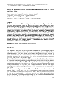
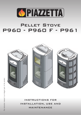
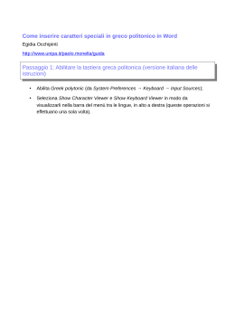
PALLADIO
PALLADIO
PELLET STOVES
Olanda
Scozia
Svizzera
Austria
Norvegia
Svezia
Danimarca
Germania
PALLADIO
Installation, operation and maintenance manual
Dear Customer,
We thank you for having chosen a Palladio stove from Edilvalli Arredi S.r.l.. Please keep this manual
safe along with your warranty certificate, and present it whenever a service engineer maintains your
stove.
ALL OUR STOVES ARE LIT AND FULLY TESTED IN THE FACTORY.
This introduction confirms the information provided in our offer for your Palladio stove. All our stoves
are made from top quality materials and are lit and fully tested in our factory before they are
despatched. If you see signs that your stove has already been used (such as pellets in the hopper or a
dirty hearth), do not worry. This simply shows that we have tested your stove in our factory and found
it to be fully functional and perfectly safe. You can therefore have every confidence in its efficiency and
safety.
PALLADIO TECHNICAL ASSISTANCE CENTRE
If your stove ever requires servicing, please ask your dealer to put you in touch with a qualified service
engineer. Alternatively you can contact the Technical Assistance Centre of Edilvalli Arredi S.r.l. directly.
We shall be happy to put you in touch with your local Technical Assistance Centre.
PALLADIO MEANS EFFECTIVENESS AND EFFICIENCY
This manual provides important information and advice that will allow you to get the most from your
new Palladio stove in terms of efficiency and safety. It also contains instructions for the regular
maintenance of your stove.
RESPONSIBILITY
Edilvalli Arredi S.r.l. declines all responsibility under civil and criminal law for damage or injury deriving
from the failure to observe, in part or in whole, the instructions contained in this manual.
Edilvalli Arredi S.r.l. declines all responsibility for damage or injury deriving from the improper use or
incorrect operation of the stove by the purchaser, from unauthorised modifications and/or repairs, and
from the use of non-original spare parts.
Edilvalli Arredi S.r.l. declines all responsibility under civil or criminal law for damage or injury caused
directly or indirectly by:
• inadequate maintenance
• failure to observe the instructions contained in this manual
• failure to observe all applicable safety precautions
• installation not conforming to applicable laws and standards in the country of installation
• installation by unqualified and/or untrained personnel
•
modifications and/or repairs performed without the manufacturer’s prior
authorisation
• the use of non-original spare parts
• exceptional events
Palladio majolica stoves – manufactured by Edilvalli Arredi S.r.l.
Dear Customer,
We thank you for your choice of a Palladio stove from Edilvalli Arredi s.r.l..
• Please keep this manual safe along with the warranty certificate, and present it whenever a
service engineer maintains your stove.
• Please remember that all our stoves are lit and fully tested in the factory.
TECHNICAL ASSISTANCE CENTRE
If your stove ever requires servicing, please contact Edilvalli Arredi S.r.l. to obtain details of your local
Technical Assistance Centre.
RESPONSIBILITY
Edilvalli Arredi S.r.l. declines all responsibility under civil and criminal law for damage or injury deriving
from the failure to observe, in part or in whole, the instructions contained in this manual.
PALLADIO
Edilvalli Arredi S.r.l. declines all responsibility for damage or injury deriving from the improper use or
incorrect operation of the stove by the purchaser, from unauthorised modifications and/or repairs, and
from the use of non-original spare parts.
Edilvalli Arredi S.r.l. declines all responsibility under civil or criminal law for damage or injury caused
directly or indirectly by:
• inadequate maintenance
• failure to observe the instructions contained in this manual
• failure to observe all applicable safety precautions
• installation by unqualified and/or untrained personnel
• installation not conforming to applicable laws and standards in the country of installation
• modifications and/or repairs performed without the manufacturer’s prior authorisation
• exceptional events
DECLARATION OF CONFORMITY
Edilvalli Arredi s.r.l. hereby declares under its own responsibility that:
the stove to which this manual relates (see nameplate) conforms to the requirements of the following
directives:
EN 14785
89/106 EEC
CPD
73/23 EEC
LVD
98/37 EEC
MACHINERY
2004/108 EEC EMC
PALLADIO
GENERAL SAFETY PRECAUTIONS
•
•
•
•
•
•
•
•
•
•
•
•
•
•
•
WARNING!
Keep this manual safe along with the warranty certificate. Read all the instructions and technical information contained in
this manual thoroughly before installing the stove.
Install the stove in conformity to all applicable local, national and European standards and legislation. When installing the
stove, make sure that you conform to applicable standards and legislation governing the extraction of fumes to flues. The
flue must have its outlet above roof height.
Have an authorised technical assistance centre clean your stove and flue thoroughly once a year. Failure to comply with
this requirements invalidates the warranty.
The stove requires air to burn its fuel. An air intake must therefore be provided outside the room where the stove is
installed in addition to a supplementary indirect air intake of at least 180 cm 2.
Bear in mind the weight of the stove when deciding where to position it. Make sure that the floor area where you intend to
locate the stove is able to support its weight before commencing installation.
If the floor is made from a flammable material (e.g. wood blocks or carpet), place a floor protector plate underneath the
stove. (The floor protector plate must extend at least 25/30 cm beyond the perimeter of the stove.)
For safety purposes, maintain a gap of at least 30 cm between the hot sides of the stove and any surrounding flammable
materials (e.g. matchboard walls, wall paper, curtains). Alternatively, install suitable insulating materials. This precaution
also applies if the stove is located near furniture like armchairs, etc.. Do not install the stove in restricted spaces unless
suitable provision is made. Do not install the stove close up to walls as this can restrict the necessary air flow. Install the
stove at least 3 cm away from all walls.
It is essential for the flue to generate sufficient draught for the stove to function correctly. The partial or complete
obstruction of the air intake to the hearth, or failure to keep the hearth properly clean can compromise the functioning of
the stove. During lighting, for example, insufficient air supply will prevent the pellets from lighting properly and cause them
to build up in the hearth. This can create excessive smoke in the combustion chamber. This in turn can lead to the
spontaneous combustion of hot gases and a violent flame. If this occurs, do not open the door to the combustion chamber.
Do not use flammable liquids to aid lighting of the pellet fuel.
Do not touch the glass of the door when the stove is hot. Do not leave children unattended near the stove when it is lit.
Hot parts can cause severe burns.
Do not attempt to remove or move the majolica panels while they are hot, as this can cause them to break.
Do not tamper with the stove. Perform only the operations specified in this manual to operate and maintain the stove.
Refer all further servicing to an authorised service engineer. Disconnect the plug from the mains power socket before
commencing any cleaning or maintenance.
Always make quite sure that the door of the combustion chamber is properly closed and hermetically sealed during the
lighting and normal functioning of the stove.
Keep the door seal fully efficient at all times. If you notice any wear or damage to the seal, ask your local Technical
Assistance Centre to replace it immediately.
The automatic lighting of the pellet fuel is the most delicate stage in the operation of the stove. Keep the stove and the
hearth thoroughly clean in order to ensure trouble-free lighting.
WARNING!
Edilvalli Arredi S.r.l. reserves the right to introduce minor changes to the component parts of this product. Such changes may
not be reflected in the contents of this manual. Edilvalli Arredi S.r.l. also reserves the right to introduce whatever changes it
deems important to the functioning and appearance of the product.
Purely aesthetic changes in the product with respect to the brochure are the result of the normal evolution and development of
Palladio stoves.
PALLADIO
TRANSPORT
•
Stove models Austria, Svizzera and Olanda do not require any special procedures, apart from
normal care and attention during moving and handling.
Proceed as follows to move and handle the Norvegia model.
1.
Carefully remove the packing.
•
4.
2.
Use the Allen key supplied to
remove the four screws from the
counter-frame, and remove the
door.
3.
Unwind the data cable from
the display.
5.
6.
Move the combustion chamber
to the place of installation.
Fit the pipes.
Move the majolica body to the
place of installation.
7.
Fit the door.
N.B.
TAKE CARE NOT TO DAMAGE THE FLAT CABLE WHEN MOVING THE STOVE.
POSITIONING THE STOVE
It is extremely important to position the stove correctly. We recommend locating the stove in the most
central point of the room you want to heat in order to ensure uniform heat distribution and maximum
efficiency.
The ideal location must also be near a flue. If the floor at the chosen position is made from flammable
material (e.g. wood blocks or carpet), place a floor protector (ACCESSORY) over it.
TECHNICAL SPECIFICATIONS OF ROOM HEATING PELLET STOVES
OLANDA
Capacity of pellet hopper
Efficiency
Max. useful heat output
Max. autonomy
Pellet consumption
Heatable room size
Weight
Max. dimensions
Dimensions of fume outlet
Dimensions of air intake
Ducting outlet
Electrical power consumption
Covering
Mains power protection
Controller protection
STANDARD EQUIPMENT
•
Room temperature sensor
•
•
Fume temperature sensor
Weekly programmer-timer
5-speed pellet feeder
•
•
•
•
•
12 Kg
91.00%
10 kW
6h
1 – 2.2 Kg/h
Depends on building insulation
98 Kg
54 x 43 x 110 cm (WxDxH)
Ø 80 mm
Ø 40 mm
Ø 60 mm
40 / 400 Watts
Top in majolica, sides in powder painted steel
alloy
Fuses
Fuses
5-speed fume extractor fan
Heat exchanger fan
Ceramic glass door
Ash box
PALLADIO
•
Infrared remote control (optional accessory - batteries not provided, 12V A23).
SCOZIA
Capacity of pellet hopper
Efficiency
Max. useful heat output
Max. autonomy
Pellet consumption
Heatable room size
Weight
Max. dimensions
Dimensions of fume outlet
Dimensions of air intake
Electrical power consumption
Covering
Mains power protection
Controller protection
•
•
•
•
•
•
•
•
•
10 Kg
91.00%
10 kW
5h
1 – 2.2 Kg/h
Depends on building insulation
98 Kg
71 x 20.5 x 109 cm (WxDxH)
Ø 80 mm
Ø 40 mm
40 / 400 Watts
Sides in powder painted steel alloy
Fuses
Fuses
STANDARD EQUIPMENT
Room temperature sensor
Fume temperature sensor
Weekly programmer-timer
5-speed pellet feeder
5-speed fume extractor fan
Heat exchanger fan
Ceramic glass door
Ash box
Infrared remote control (optional accessory - batteries not provided, 12V A23).
SVIZZERA
Capacity of pellet hopper
Efficiency
Max. useful heat output
Max. autonomy
Pellet consumption
Heatable room size
Weight
Max. dimensions
Dimensions of fume outlet
Dimensions of air intake
Ducting outlet
Electrical power consumption
Covering
Mains power protection
Controller protection
13 Kg
91.00%
13 kW
6.5 h
1 – 2.8 Kg/h
Depends on building insulation
130 Kg
66 x 45 x 115 cm (WxDxH)
Ø 80 mm
Ø 40 mm
Ø 60 mm
40 / 400 Watts
Majolica
Fuses
Fuses
STANDARD EQUIPMENT
•
•
•
•
•
•
•
•
•
Room temperature sensor
Fume temperature sensor
Weekly programmer-timer
5-speed pellet feeder
5-speed fume extractor fan
Heat exchanger fan
Ceramic glass door
Ash box
Infrared remote control (batteries not provided, 12V A23).
AUSTRIA
Capacity of pellet hopper
15 Kg
PALLADIO
Efficiency
Max. useful heat output
Max. autonomy
Pellet consumption
Heatable room size
Weight
Max. dimensions
Dimensions of fume outlet
Dimensions of air intake
Ducting outlet
Electrical power consumption
Covering
Mains power protection
Controller protection
91.00%
13 kW
6.5 h
1 – 2.8 Kg/h
Depends on building insulation
120 Kg
52 x 43 x 123 cm (WxDxH)
Ø 80 mm
Ø 40 mm
Ø 60 mm
40 / 400 Watts
Top, grille and lower covering in majolica, sides in
liquid painted steel alloy
Fuses
Fuses
STANDARD EQUIPMENT
•
•
•
•
•
•
•
•
•
Room temperature sensor
Fume temperature sensor
Weekly programmer-timer
5-speed pellet feeder
5-speed fume extractor fan
Heat exchanger fan
Ceramic glass door
Ash box
Infrared remote control (batteries not provided, 12V A23).
NORVEGIA – SVEZIA - DANIMARCA
Capacity of pellet hopper
Efficiency
Max. useful heat output
Max. autonomy
Pellet consumption
Heatable room size
Weight (Norvegia)
Weight (Svezia)
Weight (Danimarca)
Max. dimensions (Norvegia)
Max. dimensions (Svezia)
Max. dimensions (Danimarca)
Dimensions of fume outlet
Dimensions of air intake
Electrical power consumption
Covering
Mains power protection
Controller protection
•
•
•
•
•
•
•
•
•
23 Kg
91.00%
13 kW
10 h
0.6 – 2.8 Kg/h
Depends on building insulation
198 Kg
210 Kg
230 Kg
75 x 48 x 134 cm (WxDxH)
75 x 48 x 133 cm (WxDxH)
98 x 60 x 138 cm (WxDxH)
Ø 80 mm
Ø 40 mm
40 / 400 Watts
Majolica
Fuses
Fuses
STANDARD EQUIPMENT
Room temperature sensor
Fume temperature sensor
Weekly programmer-timer
5-speed pellet feeder
5-speed fume extractor fan
Heat exchanger fan
Ceramic glass door
Ash box
Infrared remote control (batteries not provided, 12V A23).
GERMANIA
Capacity of pellet hopper
30 Kg
PALLADIO
Efficiency
Max. useful heat output
Max. autonomy
Pellet consumption
Heatable room size
Weight
Max. dimensions
Dimensions of fume outlet
Dimensions of air intake
Ducting outlet
Electrical power consumption
Covering
Mains power protection
Controller protection
•
•
•
•
•
•
•
•
•
91.00%
14.5 kW
12 h
1 – 3.2 Kg/h
Depends on building insulation
250 Kg
98 x 48 x 147 cm (WxDxH)
Ø 80 mm
Ø 40 mm
Ø 60 mm
40 / 400 Watts
Majolica
Fuses
Fuses
STANDARD EQUIPMENT
Room temperature sensor
Fume temperature sensor
Weekly programmer-timer
5-speed pellet feeder
5-speed fume extractor fan
Heat exchanger fan
Ceramic glass door
Ash box
Infrared remote control (batteries not provided, 12V A23).
INSTALLATION
•
•
•
•
It is forbidden to install the stove in the following locations:
- bedrooms and bathrooms
- rooms already containing another heating appliance (fireplace, stove, etc.) that does not have its
own independent air supply.
Make sure that the electrical power socket is readily accessible.
Respect the minimum distances given below:
- Install the stove at least 50 mm away from all walls.
- If the wall is made from flammable material, increase this distance to 150 mm (and insulate the
wall with fireproof material).
- Keep all furniture, curtains, and other flammable objects at least 400 mm away from the stove.
If the stove has to be positioned on a wood floor, install it on a solid marble, ceramic or metal
plate at least 2 mm thick. This plate must be at least 30 cm deeper than the stove and at least 15
cm wider than it.
CONNECTING THE STOVE TO THE ELECTRICITY SUPPLY
Before connecting the stove to the mains electricity supply, make sure that the power socket is in
good condition and that it has an efficient earth (ground) connection.
Make sure that the mains power cable and room temperature sensor cable do not come into contact
with hot parts of the stove, e.g. the flue, and that they are not crushed by the stove, as this could lead
to short circuits.
NOTE – The stove’s electrical system is protected by fuses. Disconnect the stove from the mains power
supply before commencing any maintenance or checks!
THE FLUE
Before commencing the installation, make sure that the inside diameter of the flue and the height of
the terminal are sufficient to create an adequate draught. Also check that the flue is correctly installed
and not blocked.
Connecting the stove to the flue is an important operation that can compromise the functioning of the
stove if not done correctly. It should therefore always be done or checked by a competent and
qualified technician. Do not attempt “do-it-yourself” installations, especially if you do not have the
necessary knowledge or experience.
It is particularly important to use flue pipes that are suitable for pellet stoves and that have the proper
seals.
PALLADIO
NOTE – The pipes making up the flue must not, at any point, be smaller in diameter than the fume
outlet on the stove. To ensure the correct functioning of the stove, avoid horizontal sections of flue as
these can fill up with ash and reduce the draught. In the same way, avoid too many bends in the pipes
to ensure safe fume extraction with no loss of draught. (The complete flue should have no more than 2
bends, which must be securely fixed.)
aria per la combustione prelevata
dall’esterno
canna fumaria in muratura
Protezione isolante canna fumaria inter. H.
min 200 cm
Installation without existing chimney
Comburent air drawn from outdoors
Masonry chimney
Protective insulation around indoor section
of flue, min H. = 200 cm
Installation with existing chimney
FLUE CALCULATION TABLE FOR PELLET STOVES
PALLADIO
Type of stove
Stoves of up to 13
kW heat output
Type of flue Height and protrusion
Fig 1Da H 200cm = 0,5 – 1,5
A H 600cm = 1,5 – 3,0
Fig. 2Da H 200cm = 0,5 – 1,5
A H 600cm = 1,5 – 3,0
Fig. 3Da H 200cm = 0,5 – 1,5
A H 600cm = 1,5 – 3,0
Fig. 4Da H 200cm = 0,5 – 1,5
A H 600cm = 1,5 – 3,0
80
100
80
80
80
100
80
100
Fig. 1Da H 600cm = 0,5 – 1,5
A H 1200cm = 1,5 – 3,0
Fig. 2Da H 600cm = 0,5 – 1,5
A H 1200cm = 1,5 – 3,0
Fig. 3Da H 600cm = 0,5 – 1,5
A H 1200cm = 1,5 – 3,0
Fig. 4Da H 600cm = 0,5 – 1,5
A H 1200cm = 1,5 – 3,0
100
120
80
100
100
120
100
120
Fig. 1Da H 1200cm = 0,5 – 1,5
A H 1800cm = 1,5 – 3,0
Fig. 2Da H 1200cm = 0,5 – 1,5
A H 1800cm = 1,5 – 3,0
Fig. 3Da H 1200cm = 0,5 – 1,5
A H 1800cm = 1,5 – 3,0
Fig. 4Da H 1200cm = 0,5 – 1,5
A H 1800cm = 1,5 – 3,0
120
140
80
100
120
140
120
140
Fig. 5
Please bear in mind that the values given in the above table are intended only as guidelines to help
the installer evaluate the necessary dimensions of the flue pipes. It does not represent any specific
standard or directive. If there is an existing flue already in place, make sure that its pipes are clean and
tightly sealed. In the case of an existing masonry chimney, connect the fume outlet from the stove to
this, and install an inspection door in an accessible position to facilitate checking and cleaning.
INSTALLING THE FLUE
Fig. 1 – Installation without a masonry chimney. Ø 80 pipe: layout with one 90° bend.
The first, horizontal section of flue runs directly to the outside of the building. The second, vertical
section of flue (complete with wind cowl) runs completely outside the building. Use double wall pipes
to prevent the formation of condensation inside the flue. As shown in the figure, the vertical section of
flue (the stack) must terminate above the roof. This is a legal requirement. The higher the end of the
pipe, the more efficient the stove.
11
Fig. 2 - Installation with a masonry chimney with terminal above the roof. Ø 80 pipe: layout
with one 90° bend.
The first, horizontal section of flue connects to the existing internal or external masonry chimney. If the
stove has to be connected to a masonry chimney, or if there is an existing flue but this is too large in
size, route steel flue pipes of no less than Ø 80 mm up through it. The wind cowl must terminate
higher than the apex of the roof.
INSTALLING THE COMBURENT AIR PIPE
The following instructions are valid for figures 1 and 2.
PALLADIO
Two alternative installations are possible for both types of flue installation:
1. Air can be drawn from outdoors through a pipe connected to the air inlet at the rear of the
stove. This is the recommended method as it prevents fumes and smells from escaping into
the room.
2. Air can be drawn directly from the room where the stove is installed. If this option is preferred,
you must install an air vent of at least 180 cm² through an outside wall near the stove. It is
possible that you might detect a slight smell of burned wood in the house if comburent air is
drawn from the room itself.
NOTE – In either case, check regularly that the passage of air is not restricted or blocked in any way.
Protect the air inlet with a suitable grille and check it at regular intervals.
Important points:
• The air intake must be of adequate dimensions.
• Horizontal sections of flue must have a slope of > 5° and a length of < 2 metres.
• The vertical section of flue (the stack) must have a height of > di 2 metres.
• There must be provision for inspecting all sections of the flue.
• Mastic or a high temperature sealant should be used to seal the flue at the point where it connects
to the stove’s fume outlet.
• Provide a drain point for condensate and ash.
NOTE - Never connect the flue from this stove to a flue for another stove or fireplace, etc..
PELLET FUEL
Pellet fuel comes in the form of small cylindrical pellets of about 6 mm in diameter. These are made
from compressed sawdust and waste wood chippings, with no additives, colouring agents or other
materials.
Technical specifications of wood pellets:
• diameter: 6 – 6.5 millimetres
• maximum length: 20-25 mm
• maximum humidity: 8%
• calorific value: approx. 4,800 kcal/kg.
NOTE – The use of pellets with different specifications to those given above may reduce the heat
output of the stove, lead to the formation of residues, cause poor combustion, and even make it
necessary to recalibrate the stove's parameters.
The manufacturer cannot guarantee the proper functioning of the stove if pellets with specifications
other than those given above are used as fuel.
CLEANING
Proper cleaning and maintenance are essential to the correct functioning of the stove. Failu re to
respect the following instructions invalidates the warranty.
• Ordinary daily cleaning to be performed by the user (before lighting the stove, while it is still
cold):
- Open the door and vacuum clean the fire box.
- Remove the hearth, clean it and make sure that the holes in it are not blocked.
- Vacuum clean the hearth compartment, clean all contact edges and fit the hearth again,
ensuring that it is seated securely.
- Empty the ash box, if fitted.
PALLADIO
- Clean the glass with a damp cloth (only when the stove is cold).
- Carefully close the door.
• Extraordinary annual cleaning to be performed by the service engineer:
- Perform general cleaning of the inside and outside of the stove’s flue pipes.
- Remove the furnace linings, and thoroughly clean and decoke the hearth and hearth compartment.
- Clean the fans, check them for play and check their mountings.
- Clean, inspect and decoke the glow plug igniter and its housing.
- Check the door seal and replace if necessary.
- Clean the display.
- Inspect the electrical control cables and connections and the mains power cable.
- Clean the pellet hopper and check the feed screw and gearmotor for play.
- Check the functioning of the feed screw, fill the hopper and check the stove lighting sequence.
- Inspect and clean the fume outlet.
- Inspect the flue and check the draught. Clean the flue or instruct the user to have it cleaned if
necessary.
NOTE – The glow plug igniter and the hearth compartment are both subject to wear. Check and
replace if necessary.
STARTING UP ROOM HEATING STOVES
The control panel incorporates a display that shows information on the functioning of the stove.
When the stove is first switched on, before lighting occurs, the display appears as shown in Fig. 6.
Fig. 6
orologio
temperatura ambiente
spento
stato
dialogo
potenza
Clock
Room temperature
Off
Status
Display message
Heat output level
The control panel provides a menu via which you can view and set functioning parameters (depending
on your access level). All control keys have a number to identify them.
Fig. 7
crono
candeletta
Timer
Igniter
PALLADIO
coclea
aspiratore fumi
scambiatore
non usato
allarme
Feed screw
Fume extractor fan
Heat exchanger fan
Not used
Alarm
Fig. 7 shows the meaning of the status indicators on the left of the display.
When a status indicator lights up, it shows that the device corresponding to it is functioning.
SWITCHING THE STOVE ON
To switch the stove on, press and hold key (4) (the ON/OFF key) for a few seconds. See Fig. 8. Press
and hold the same key again to switch the stove off. The complete functioning cycle comprises five
separate stages (lighting, flame stabilisation, normal functioning, economy functioning and shutdown).
The stove switches between these stages on the basis of fume temperature and parameter settings.
Fig.8
orologio
temperatura ambiente
dialogo
potenza
Clock
Room temperature
Display message
Heat output level
LIGHTING THE STOVE
Lighting begins when the glow plug igniter is switched on and the feed screw charges pellets into the
stove. The display reads out, in succession, the messages “CLEANING HEARTH”, “LIGHTING”,
“CHARGING PELLETS” and “WAITING FOR FLAME”. After about 45 seconds, the feed screw stops and
the fume extractor fan starts (at the predefined speed for this stage). As soon as the pellet fuel starts
to burn, and fume temperature reaches 50 C°, the glow plug igniter switches off and the stove
controller switches to the flame stabilisation stage.
The lighting stage finishes when fume temperature reaches 50 C°, but the functioning time of the glow
plug igniter is limited to a maximum of 15 minutes for safety reasons and to prevent damage.
If the pellet fuel has not lit within this 15 minute period, the display reads out the alarm message
“LIGHTING FAILED”.
timer
Timer
temperatura ambiente
Room temperature
dialogo
Display message
potenza
Power output level
Fig. 9
PALLADIO
FLAME STABILISATION
During flame stabilisation the feed screw charges pellets into the stove at the predetermined speed for
this stage. When fume temperature exceeds 100 C°, the stove’s controller switches to normal
functioning mode. During flame stabilisation, the fume extractor fan runs at the predetermined speed
for the stage. Provided temperature remains stable for a predetermined period of time, the stove’s
controller switches to normal functioning mode. You can bypass the start-up stages by pressing and
holding the increase power key (6) for about 3 seconds. This forces the stove directly into normal
functioning mode.
NORMAL FUNCTIONING
The stove’s controller provides an input for a room thermostat. Depending on the settings made on
the room thermostat and on actual room temperature, the stove can function on a number of ways:
- T amb: this is the temperature measured by the room temperature sensor.
- T setAmb: this is the temperature set on the room thermostat.
- T setTerm: this is the setting of the ROOM TEMPERATURE SETPOINT.
Room thermostat closed (Tamb >TsetTerm): the display reads out the message “ton” and the stove
runs at the predetermined power setting until the thermostat opens.
Room thermostat open (TAmb>TsetTerm): the stove runs at the predetermined power setting until
TsetTerm temperature is reached (Tamb<TsetTerm), and then switches to economy mode.
Fig. 10
orologio
temperatura ambiente
dialogo
potenza
Clock
Room temperature
Display message
Heat output level
TEMPERATURE MODULATION
The stove enters temperature modulation mode if room temperature reaches the value set in the
“TEMPERATURE SETTING”. In temperature modulation mode, the feed screw, the fume extractor fan
and the heat exchanger fan all run at minimum speed and the display reads out the message
“MODULATING MODE”.
Fig . 11
PALLADIO
SHUTDOWN
To shut down the stove, press and hold the ON/OFF key (4) for a few seconds. The feed screw stops,
the fume extractor fan slows to the predetermined speed, and the display reads out the message
“FINAL CLEANING”. When fume temperature falls to the minimum functioning threshold, the heat
exchanger fan switches off. Then, after a delay of about 10 minutes, the fume extractor fan also stops.
Fig. 12
RE-LIGHTING THE STOVE
You cannot re-light the stove until fume temperature falls below the value set in parameter Pr13
(about 50°) and the safety time set in parameter Pr38 (about 10 minutes) has also passed.
ALARM SIGNALLING
If any malfunction occurs, an alarm message appears on the display. The following is a list of the alarm
messages that can appear.
MESSAGE ON DISPLAY
1.
FUME TEMP. ALARM
2.
ALARM HOT TEMP.
3.
LIGHTING FAILURE
4.
LIGHTING FAILURE
5.
ALARM BLACKOUT
6.
ALARM DEP FAIL
DESCRIPTION OF ALARM
Fume temperature sensor malfunction
Fume overtemperature
The lighting stage has failed
The stove has gone out during normal functioning
Mains power failure
Safety pressure switch error
7. ALARM SIC FAIL
General safety thermostat alarm
8.
Extractor fan malfunction
ALARM FAL FAIL
Fig. 13
NOTE – All alarm conditions cause the immediate shutdown of the stove.
An alarm status is signalled after the delay set in parameter Pr11. Alarm status can be reset by
pressing key (4). Switch off the stove, ascertain what is causing the alarm, eliminate the cause, and
then light the stove again. If the alarm occurs again, contact your Technical Assistance Centre.
1. FUME TEMPERATURE SENSOR ALARM
This alarm shows that the fume temperature sensor is malfunctioning. The stove initiates the
shutdown procedure if this alarm occurs.
2. FUME OVERTEMPERATURE ALARM
PALLADIO
This alarm shows that the fume temperature sensor has detected a temperature in excess of 250°C.
The display reads out the message shown in Fig. 14.
Fig. 14
3. LIGHTING FAILURE ALARM
This alarm shows that the lighting stage has terminated without the fuel lighting.
Fig. 15
4. FLAME OUT DURING NORMAL FUNCTIONING ALARM
This alarm shows that the stove has gone out and that fume temperature has dropped below the
minimum operating threshold (parameter Pr13) during the course of normal functioning.
5. DRAUGHT SAFETY SWITCH ALARM
If the draught in the flue falls to a level below the minimum operating threshold, the draught (negative
pressure) safety switch trips. This stops the feed screw (since it is wired in series with the feed screw
gearmotor) and at the same time informs the controller of the stoppage via pin AL2 of connector CN4.
The display reads out “Alarm Dep Fail” and the stove shuts down.
6. GENERAL SAFETY THERMOSTAT ALARM (depending on model)
If temperature in the flue rises above the maximum operating threshold, the general safety thermostat
trips. This stops the feed screw (since it is wired in series with the feed screw gearmotor) and at the
same time informs the controller of the stoppage via pin AL1 of connector CN4. The display reads out
“Alarm Sic Fail” and the stove shuts down.
7. EXTRACTOR FAN MALFUNCTION ALARM
(depending on model)
A malfunction of the fume extractor fan shuts down the stove and displays the “Alarm Fal Fail”. The
appearance of this alarm initiates the shutdown procedure immediately.
MENU
Press the MENU key (3) to access the menu.
PALLADIO
The menu contains various levels and functions through which you can access settings and program
the controller. To access the menu, press and hold the menu key (3) key for two seconds, then press
keys (5) and (6) to scroll through the sub-menus. When you reach the sub-menu you want, press key
(3) again to confirm your selection.
• 01 FAN SETTINGS MENU
• 02 CLOCK MENU
• 03 TIMER MENU
• 04 LANGUAGE MENU
• 05 STANDBY MENU
• 06 BUZZER MENU
• 07 INITIAL CHARGING MENU
• 08 MODE MENU
• 09 PARAMETERS MENU
02 - CLOCK MENU
This menu lets you set the current time and date. The controller is fitted with a lithium battery that
gives the internal clock an autonomy of 3 to 5 years.
input
User input
livello di menu
Menu level
dialogo
Display message
Fig. 16
Go to the CLOCK menu and press keys (5) and (6) to scroll through the values. Press key (3) to confirm
your settings.
Sub-menu 03 - 01 – Enable timer
03 - TIMER MENU
This sub-menu lets you enable and disable timer-programmer functions in general.
Fig. 17
Sub-menu 03 - 02 – Daily programming
This sub-menu lets you enable, disable and set the daily timer-programmer.
PALLADIO
You can create two time bands starting and ending at the times you enter, as shown in the table
below. The OFF setting instructs the timer-programmer to ignore the parameter.
Fig. 18
Fig. 19
Selection
START 1
STOP 1
START 2
STOP 2
Meaning
Start-up time
Shutdown time
Start-up time
Shutdown time
Possible values
Time - OFF
Time - OFF
Time - OFF
Time - OFF
Sub-menu 03 - 03 – Weekly programming
This sub-menu lets you enable, disable and set the weekly timer-programmer.
Fig. 20
input
livello di menu
dialogo
stato
User input
Menu level
Display message
Status
The weekly timer-programmer provides 4 independent weekly programs. The effect of these depends
on how the 4 time band settings are programmed.
You can enable or disable the weekly timer-programmer. If you enter an OFF setting in a time field,
the timer ignores the field.
PALLADIO
Fig. 21
PROGRAMMA 1
livello di menu
selezione
significato
valori possibili
START PROG 1
STOP PROG 1
LUNEDI’ PROG 1
MARTEDI’ PROG 1
MERCOLEDI’ PROG 1
GIOVEDI’ PROG 1
VENERDI’ PROG 1
SABATO PROG 1
DOMENICA PROG 1
ora di attivazione
ora di disattivazione
giorno di riferimento
ora/OFF
on/off
PROGRAM 1
Menu level
Selection
Meaning
Possible values
START PROG 1
STOP PROG 1
MONDAY PROG 1
TUESDAY PROG 1
WEDNESDAY PROG 1
THURSDAY PROG 1
FRIDAY PROG 1
SATURDAY PROG 1
SUNDAY PROG 1
Start-up time
Shutdown time
Day applicable
Time - OFF
On/Off
NOTE – Take special care when programming to avoid overlapping start-up and shutdown times for
different programs on the same day.
Sub-menu 03 - 04 – Weekend programming
This sub-menu lets you enable, disable and set timer-programmer functions for weekends (days 6 and
7,i.e. Saturday and Sunday).
Fig. 22
NOTE – In order to avoid confusion and unwanted start-ups and shutdowns, set just one time band for
weekends unless you know exactly what time bands you require.
If you wish to apply the weekly program on weekends too, simply disable the weekend program. Keep
the weekend program disabled to use weekday programs 1, 2, 3 and 4.
PALLADIO
Deactivate the weekly program before activating the weekend program.
04 – LANGUAGE MENU
This menu lets you select the display language from a list of available languages.
Fig. 23
05 – STANDBY MENU
This menu lets you activate “STANDBY” mode. In standby mode, the stove shuts down if room
temperature remains above the temperature setpoint for a time in excess of that set in parameter
Pr44.
If the stove shuts down under these conditions, you can only re-light it when the following condition
occurs:
TSET < (Tambient – Pr43)
06 - BUZZER MENU
If this function is turned “OFF”, the buzzer is disabled.
07 - INITIAL CHARGING MENU
When the stove is shut down and cold, this menu lets you load a charge of pellets for a time of 4
seconds. Press key (1) to start charging and press key (4) to stop charging. Only use this function if the
hopper has run out and has been refilled.
Fig. 24
CHANGING THE ROOM TEMPERATURE SETPOINT
Press keys (1) and (2) to change the room temperature setpoint. The display shows the current
temperature setpoint.
PALLADIO
Fig. 25
valore impostato
Temperature setting
CHANGING HEAT OUTPUT
Press keys (5) and (6) to decrease or increase the stove’s heat output. All related functions are updated
automatically. The display shows the heat output selected. If the temperature measured by the room
temperature sensor exceeds the temperature setpoint on the display, the controller automatically
reduces heat output to the minimum setting (level 1).
Fig. 26
MODE MENU
The mode menu determines how the stove functions. The stove can function in one of two modes:
• manual: the stove functions continuously. In manual mode, press the ON/OFF key to light and
shut down the stove.
• automatic: the controller lights and shuts down the stove automatically in accordance with
the weekly programme (see the weekly programme menu).
Press the ENTER key to confirm your settings, or press the function key to cancel them. Once you have
entered a setting, the stove display returns to the main menu.
You can switch between manual and automatic mode by pressing the relevant key on the display.
THE INFRARED REMOTE CONTROL
You can use the remote control to light and shut down the stove, change the room temperature
setpoint and change heat output. The remote control cannot be used to change any other parameters.
You can enable and disable the remote control using the remote control function in the parameters
menu.
PALLADIO
Using the remote control:
− Press the two + keys (1 and 6) simultaneously to light and shut down the stove.
− Press the left hand + and – keys with the thermometer symbol (1 and 2) to increase or
decrease the room temperature setpoint.
− Press the right hand + and – keys with the flame symbol (5 and 6) to increase or decrease the
stove’s heat output.
TROUBLESHOOTING
Display blank and keys not
working.
No mains power or
control panel cable not
properly connected.
Check that the mains power cable and the
control panel cable are properly connected.
Remote control not working.
1.
1.
2.
Too far away from
stove.
Batteries discharged.
Move closer to the stove.
2.
Check the batteries and change if
necessary.
Clean out the hearth (see the “Cleaning”
section).
The stove will not light.
ALARM 5.
Too much fuel in the
hearth.
The stove does not light
automatically.
The glow plug igniter is
not getting hot.
Check the electrical wiring and fuses.
Check the glow plug igniter and replace if
necessary (operation reserved for Technical
Assistance).
The glow plug igniter is
damaged or worn out.
Check the glow plug igniter and replace if
necessary (operation reserved for Technical
Assistance).
No pellets coming down
the chute.
!! Disconnect the stove from the mains
electricity supply before commencing!
Check that the pellets are not jammed on the
chute.
Check that the feed screw is not jammed.
Check the door seal and replace if necessary.
1. Clean the hearth.
2. Check the hopper and refill if necessary.
3. Fill the feed screw (see “Starting up room
heating stoves”).
ALARM 5.
The stove shuts down.
ALARM 5.
Air from the stove is not warm.
1.
The
stove
has
functioned for a long
time
without
the
hearth being cleaned.
2. The pellet hopper is
empty.
3. The feed screw is not
charging pellets.
Too much soot in the flue
pipes.
Clean the flue pipes (operation reserved for
Technical Assistance) and update the fan
control parameters.
PALLADIO
Display blank and keys not
working.
No mains power or
control panel cable not
properly connected.
Check that the mains power cable and the
control panel cable are properly connected.
The stove becomes clogged
quickly and combustion is
uneven.
The flue is too long or
twisted.
Adjust comburent air flow.
The pellets are damp.
Check the pellets.
The hearth has been
charged with too many
pellets.
Gradually reduce pellet feed in the
“Parameters” menu (operation reserved for
Technical Assistance).
Fit a wind-proof flue terminal.
Wind is blowing into the
stove from outdoors.
The stove shuts down for lack of
pellets.
Insufficient air is getting to
the hearth.
Check that the hearth and comburent air duct
are both clean and correctly positioned.
Check all the seals and check the flue for
cleanliness.
The flue is blocked.
Clean as necessary.
The type of pellet fuel has
changed.
Reduce pellet feed in the “Parameters” menu. If
the problem persists, contact Technical
Assistance.
!! Disconnect the stove from the mains
electricity supply before commencing!
The
feed
screw
malfunctioning.
is
PELLETS FINISHED ALARM.
- Remove any blockages from the feed screw.
- Remove any blockages from the chute.
- Remove any pellet dust from the bottom of
the hopper.
The temperature setpoint
has been reached.
This is normal functioning. The stove will return
to full power when room temperature falls.
STOVE CONTROLLER ELECTRICAL BLOCK DIAGRAM
PALLADIO
TRASFORMATORE
DISPLAY
SERIALE
CRONO
FILTRO DI RELè
FUS
ENCODER
SONDE AMBIENTE
TERMOSTATO SUPPLEMENTARE
SONDA FUMI
ENCODER
SCAMBIATORE SECONDARIO N.2
TERRA
RETE
VENTILATORE FUMI
SCAMBIATORE PRINCIPALE
COCLEA
CANDELETTA
ALF= Termostato Sicurezza generale
ALC = Depressimetro
ALP = Temostato Sicurezza Vano Pellet
(*) Vedi paragrafo corrispondente per il
corretto utilizzo
TRANSFORMER
DISPLAY CONNECTOR
SERIAL CONNECTOR
TIMER
RELAY FILTER
FUSE
ENCODER
ROOM TEMPERATURE SENSOR
SUPPLEMENTARY THERMOSTAT
FUME TEMPERATURE SENSOR
ENCODER
SECONDARY HEAT EXCHANGER N.2
EARTH (GROUND)
MAINS
EXTRACTOR FAN
MAIN HEAT EXCHANGER
FEED SCREW
GLOW PLUG IGNITER
ALF = General safety thermostat
ALC = Draught pressure switch
ALP = Pellet compartment safety thermostat
(*) See the relevant instructions for correct
operation.
PALLADIO
Palladio majolica stoves
Edilvalli Arredi S.r.l.
Via Oselin, s.n.
33047 Remanzacco (UD) - Italy
tel. 0432/1744006 fax 0432/1744007
[email protected]
www.stufepalladio.com
PALLADIO
MODULO 1° COLLAUDO
La presente scheda deve essere compilata a cura del tecnico Palladio al momento del primo collaudo.
DATI del CLIENTE
DATA COLLAUDO
COGNOME/NOME
ESSENZA
PELLET
MODELLO
MATRICOLA
LUNGHEZZA
TARATURE FABBRICA
TARATURE VARIE
TARATURE TECNICO
PELLET
PARAMETRO
Pr01
Pr02
Pr03
Pr04
Pr05
Pr06
Pr07
Pr08
Pr09
Pr10
Pr11
Pr12
Pr13
Pr14
Pr15
Pr16
Pr17
Pr18
Pr19
Pr20
Pr21
Pr22
Pr23
Pr24
Pr25
Pr26
Pr27
Pr28
Pr29
Pr30
Pr31
Pr32
Pr33
Pr34
Pr35
Pr36
Pr37
Pr38
Pr39
Pr40
Pr41
Pr42
Pr43
Pr44
Pr45
Pr46
Pr47
Pr48
LIVELLO
DI MENU'
M-9-7-01
M-9-7-02
M-9-7-03
M-9-7-04
M-9-7-05
M-9-7-06
M-9-7-07
M-9-7-08
M-9-7-09
M-9-7-10
M-9-7-11
M-9-7-12
M-9-7-13
M-9-7-14
M-9-7-15
M-9-7-16
M-9-7-17
M-9-7-18
M-9-7-19
M-9-7-20
M-9-7-21
M-9-7-22
M-9-7-23
M-9-7-24
M-9-7-25
M-9-7-26
M-9-7-27
M-9-7-28
M-9-7-29
M-9-7-30
M-9-7-31
M-9-7-32
M-9-7-33
M-9-7-34
M-9-7-35
M-9-7-36
M-9-7-37
M-9-5-01
M-9-5-02
M-9-5-03
M-9-5-04
M-9-5-05
M-9-5-06
M-9-5-07
M-9-5-08
M-9-5-09
M-9-5-10
M-9-5-11
DESCRIZIONE
Tempo massimo del ciclo di accensione
Tempo di avvio
Intervallo di tempo tra le due pulizie del braciere
Tempo di ON motore coclea nella fase di accensione
Tempo di ON motore coclea nella fase di avvio
Tempo di ON motore coclea nella fase di lavoro a potenza 1
Tempo di ON motore coclea nella fase di lavoro a potenza 2
Tempo di ON motore coclea nella fase di lavoro a potenza 3
Tempo di ON motore coclea nella fase di lavoro a potenza 4
Tempo di ON motore coclea nella fase di lavoro a potenza 5
Ritardo allarmi
Durata pulizia braciere
Temperatura minima fumi per considerare la stufa accesa
Soglia di allarme temperatura massima
Soglia di temperatura fumi per accendere gli scambiatori
Velocità aspirazione fumi nella fase di accensione
Velocità aspirazione fumi nella fase di avvio
Velocità aspirazione fumi nella fase di lavoro a potenza 1
Velocità aspirazione fumi nella fase di lavoro a potenza 2
Velocità aspirazione fumi nella fase di lavoro a potenza 3
Velocità aspirazione fumi nella fase di lavoro a potenza 4
Velocità aspirazione fumi nella fase di lavoro a potenza 5
Velocità motore scambiatore 1 nella fase di lavoro a potenza 1
Velocità motore scambiatore 1 nella fase di lavoro a potenza 2
Velocità motore scambiatore 1 nella fase di lavoro a potenza 3
Velocità motore scambiatore 1 nella fase di lavoro a potenza 4
Velocità motore scambiatore 1 nella fase di lavoro a potenza 5
Temperatura fumi per passare in modalità ECO-MODULA
Velocità aspirazione fumi nella fase di pulizia braciere
Tempo di ON motore coclea nella fase di pulizia
Abilitazione encoder
Tempo frenatura coclea
Tempo Pulizia Iniziale
Tempo preriscaldamento
Velocità fumi pulizia iniziale
Velocità fumi preriscaldamento
Velocità fumi attesa
Blocco riaccensione
Tempo di spegnimento aspiratore fumi
Tempo di precaria in accensione
Tempo di attesa dopo precarica
Velocità aspiratore fumi in fase di precarica
Isteresi temperatura ON/OFF in modalità automatica
Ritardo allo spegnimento in modalità automatica
Ritardo cambio potenza
Abilitazione comando del remoto
Abilitazione blocco tastiera
Riaccensione automatica dopo black-out
UNITA'
MISURA
minuto
minuto
secondo
secondo
secondo
secondo
secondo
secondo
secondo
secondo
secondo
secondo
C°
C°
C°
volt
volt
volt
volt
volt
volt
volt
volt
volt
volt
volt
volt
°C
volt
secondo
secondo
secondo
secondo
volt
volt
volt
minuto
minuto
secondo
secondo
volt
°C
minuto
secondo
secondo
VALORI
IMPOSTATI
PALLADIO
MODULO 1° COLLAUDO
La presente scheda deve essere compilata a cura del
tecnico Palladio al momento del primo collaudo.
DATI del CLIENTE
DATA COLLAUDO
COGNOME/NOME
MODELLO
MATRICOLA
ESSENZA PELLET
LUNGHEZZA
TARATURE TECNICO
TARATURE VARIE
TARATURE FABBRICA
PARAMETRO
LIVELLO DI MENU’
DESCRIZIONE
UNITA’ MISURA
VALORI IMPOSTATI
minuto
secondo
VOLT
C°
Pr01 Tempo massimo del ciclo di accensione
Pr02 Tempo di avvio
Pr03 Intervallo di tempo tra le due pulizie del braciere
Pr04 Tempo di ON motore coclea nella fase di
accensione
Pr05 Tempo di ON motore coclea nella fase di avvio
Pr06 Tempo di ON motore coclea nella fase di lavoro a
potenza 1
Pr07 Tempo di ON motore coclea nella fase di lavoro a
potenza 2
Pr08 Tempo di ON motore coclea nella fase di lavoro a
potenza 3
Pr09 Tempo di ON motore coclea nella fase di lavoro a
potenza 4
Pr10 Tempo di ON motore coclea nella fase di lavoro a
potenza 5
Pr11 Ritardo allarmi
Pr12 Durata pulizia braciere
Pr13 Temperatura minima fumi per considerare la stufa
accesa
Pr14 Soglia di allarme temperatura massima
Pr15 Soglia di temperatura fumi per accendere gli
scambiatori
Pr16 Velocità aspirazione fumi nella fase di accensione
Pr17 Velocità aspirazione fumi nella fase di avvio
Pr18 Velocità aspirazione fumi nella fase di lavoro a
potenza 1
Pr19 9 Velocità aspirazione fumi nella fase di lavoro a
potenza 2
Pr20 Velocità aspirazione fumi nella fase di lavoro a
potenza 3
Pr21 Velocità aspirazione fumi nella fase di lavoro a
potenza 4
Pr22 Velocità aspirazione fumi nella fase di lavoro a
potenza 5
Pr23 Velocità motore scambiatore 1 nella fase di lavoro
a potenza 1
Pr24 Velocità motore scambiatore 1 nella fase di lavoro
COMMISSIONING FORM
This form must be compiled by the Palladio engineer
on commissioning of the stove.
DETAILS OF PURCHASER
COMMISSIONING DATE
NAME/SURNAME
MODEL
SERIAL NUMBER
PELLET TYPE
LENGTH
TECHNICAL SETTINGS
VARIOUS SETTINGS
FACTORY SETTINGS
PARAMETER
MENU LEVEL
DESCRIPTION
UNIT OF MEASUREMENT
SETTING VALUES
minute
second
Volt
C°
Pr01 Lighting cycle timeout
Pr02 Start-up time
Pr03 Hearth cleaning interval
Pr04 Feed screw ON time during lighting
Pr05 Feed screw ON time during start-up
Pr06 Feed screw ON time during normal functioning at
level 1
Pr07 Feed screw ON time during normal functioning at
level 2
Pr08 Feed screw ON time during normal functioning at
level 3
Pr09 Feed screw ON time during normal functioning at
level 4
Pr10 Feed screw ON time during normal functioning at
level 5
Pr11 Alarm delay
Pr12 Hearth cleaning duration
Pr13 Minimum fume temperature for stove to be
considered lit
Pr14 Maximum alarm temperature threshold
Pr15 Fume temperature threshold for starting heat
exchangers
Pr16 Fume extractor fan speed during lighting
Pr17 Fume extractor fan speed during start-up
Pr18 Fume extractor fan speed during normal functioning
at level 1
Pr19 Fume extractor fan speed during normal functioning
at level 2
Pr20 Fume extractor fan speed during normal functioning
at level 3
Pr21 Fume extractor fan speed during normal functioning
at level 4
Pr22 Fume extractor fan speed during normal functioning
at level 5
Pr23 Heat exchanger fan speed during normal
functioning at level 1
Pr24 Heat exchanger fan speed during normal
PALLADIO
a potenza 2
Pr25 Velocità motore scambiatore 1 nella fase di lavoro
a potenza 3
Pr26 Velocità motore scambiatore 1 nella fase di lavoro
a potenza 4
Pr27 Velocità motore scambiatore 1 nella fase di lavoro
a potenza 5
Pr28 Temperatura fumi per passare in modalità ECOMODULA
Pr29 Velocità aspirazione fumi nella fase di pulizia
braciere
Pr30 Tempo di ON motore coclea nella fase di pulizia
Pr31 Abilitazione encoder
Pr32 Tempo frenatura coclea
Pr33 Tempo Pulizia Iniziale
Pr34 Tempo preriscaldamento
Pr35 Velocità fumi pulizia iniziale
Pr36 Velocità fumi preriscaldamento
Pr37 Velocità fumi attesa
Pr38 Blocco riaccensione
Pr39 Tempo di spegnimento aspiratore fumi
Pr40 Tempo di precaria in accensione
Pr41 Tempo di attesa dopo precarica
Pr42 Velocità aspiratore fumi in fase di precarica
Pr43 Isteresi temperatura ON/OFF in modalità
automatica
Pr44 Ritardo allo spegnimento in modalità automatica
Pr45 Ritardo cambio potenza
Pr46 Abilitazione comando del remoto
Pr47 Abilitazione blocco tastiera
Pr48 Riaccensione automatica dopo black-out
functioning at level 2
Pr25 Heat exchanger fan speed during normal
functioning at level 3
Pr26 Heat exchanger fan speed during normal
functioning at level 4
Pr27 Heat exchanger fan speed during normal
functioning at level 5
Pr28 Fume temperature for switching to eco-modulating
mode
Pr29 Fume extractor fan speed during hearth cleaning
Pr30 Feed screw ON time during hearth cleaning
Pr31 Encoder enabling
Pr32 Feed screw slowing time
Pr33 Initial cleaning time
Pr34 Preheating time
Pr35 Fume extractor fan speed during initial cleaning
Pr36 Fume extractor fan speed during lighting
Pr37 Fume extractor fan speed during waiting
Pr38 Re-lighting delay
Pr39 Fume extractor fan off time
Pr40 Pre-charge time during lighting
Pr41 Wait time after pre-charging
Pr42 Extractor fan speed during pre-charging
Pr43 ON/OFF hysteresis temperature interval in
automatic mode
Pr44 Shutdown delay in automatic mode
Pr45 Power level switching delay
Pr46 Remote control enabling
Pr47 Key lock enabling
Pr48 Automatic re-lighting after power failure
DESCRIZIONE DETTAGLIATA DEL COLLEGAMENTO DEL TUBO DI SCARICO FUMI ALLA CANNA FUMARIA
PALLADIO
(OBBLIGATORIA PER LEGGE).
COGNOME/NOME TECNICO
FIRMA del TECNICO
Il sottoscritto conferma che il tecnico Palladio gli ha fornito tutte le delucidazioni tecniche necessarie al corretto utilizzo e alla
giusta manutenzione della stufa; pertanto attesta di non aver alcuna riserva da dichiarare.
FIRMA del CLIENTE
IMPORTANTE: Presentare la scheda ad ogni successivo intervento da parte del tecnico Palladio.
SUCCESSIVI INTERVENTI
DATA INTERVENTO
DESCRIZIONE DETTAGLIATA DEL
DESCRIZIONE DETTAGLIATA DELL'INTERVENTO
DETAILED DESCRIPTION OF CONNECTION
PALLADIO
COLLEGAMENTO DEL TUBO DI SCARICO FUMI
ALLA CANNA FUMARIA (OBBLIGATORIA PER LEGGE).
COGNOME/NOME TECNICO
FIRMA del TECNICO
Il sottoscritto conferma che il tecnico Palladio gli ha
fornito tutte le delucidazioni tecniche necessarie al
corretto utilizzo e alla giusta manutenzione della stufa;
pertanto attesta di non aver alcuna riserva da dichiarare.
FIRMA del CLIENTE
IMPORTANTE: Presentare la scheda ad ogni successivo
intervento da parte del tecnico Palladio.
SUCCESSIVI INTERVENTI
DATA INTERVENTO
DESCRIZIONE DETTAGLIATA
DELL'INTERVENTO
BETWEEN STOVE EXHAUST AND FLUE (LEGAL
REQUIREMENT).
NAME/SURNAME OF COMMISSIONING
ENGINEER
SIGNATURE OF COMMISSIONING ENGINEER
I, the undersigned, hereby confirm that Palladio’s
commissioning engineer has provided me with all the
technical explanations necessary for the correct operation
and maintenance of the stove and that I unreservedly
accept the product.
SIGNATURE OF CUSTOMER
IMPORTANT: This form must be presented to the
Palladio service engineer whenever the stove is
serviced.
SUBSEQUENT WORK
DATE OF WORK
DETAILED DESCRIPTION OF WORK PERFORME
CERTIFICATE OF WARRANTY
Purpose of this certificate
This certificate, presented along with an invoice and/or tax receipt or bill of sale, is the only document valid for the purpose of recognising the warranty.
It must be presented to the manufacturer's service engineer whenever work is performed on the stove.
All copies of this certificate of warranty must be compiled in full. The first section must be completed by the retailer. The second section must
be completed by the Technical Assistance Centre’s service engineer as part of mandatory commissioning.
Terms of the warranty
1- The manufacturer guarantees this stove to be free from defects for a period of twenty-four (24) months starting from the date of purchase, when
installed anywhere in Italy.
2- This certificate of warranty must be kept and presented, along with proof of purchase, to the service engineer of the Palladio Technical Assistance
Centre whenever work is performed on the stove. This certificate of warranty must be stamped and signed by the retailer. The section reserved for the
Technical Assistance Centre must be compiled before this certificate is returned by post to Edilvalli Arredi S.r.l..
3- The manufacturer hereby undertakes to repair, free of charge, any parts proven to be defective at origin. This warranty only applies to the original
purchaser.
4- The present warranty only applies to faults deriving from defects in manufacturing. It expressly excludes faults caused by insufficient or incorrect
maintenance, unsuitable or incorrect operation, incorrect installation, improper use, the purchaser’s negligence and/or lack of care, use of unsuitable fuel
types, and any other cause not directly dependent on Edilvalli Arredi. It also expressly excludes damage caused to parts during transport of which the
manufacturer is not notified within four (4) days from the delivery of the product, and damage caused by natural events and acts of God (earthquakes,
floods, lightning strikes, etc.).
5- This warranty expressly excludes the responsibility of Edilvalli Arredi for damage or injury caused directly or indirectly to persons, animals or property,
incurred through loss of use, and for any other economic losses resulting from use of the stove or from the enforced suspension of that use.
6- Any tampering, modification or repair to the stove by personnel not authorised by Palladio automatically invalidates the warranty. Repairs performed
during the warranty period do not extend or renew the warranty’s validity period in any way. Failure to have the stove serviced annually by an authorised
Technical Assistance Centre also invalidates the warranty.
7- The present warranty does not affect the purchaser’s legal rights; it is intended to complement consumer protection legislation and not replace it.
8- All installation and commissioning costs, as well any call-out and transfer fees for installation and commissioning engineers are entirely at the
purchaser’s expense. All call-out fees and costs incurred for the recalibration and fine tuning of the product not due to its control devices are also at the
purchaser’s own expense. Edilvalli Arredi declines all responsibility for fumes leaking or escaping from the stove if it is not installed in conformity to
applicable directives and legislation.
9- PALLADIO undertakes to replace all parts proven to be defective for a period of two (2) years. This warranty excludes all additional costs
incurred for call-out fees, consumables, labour, transport, telehandlers, scaffolding, and any other form of lifting equipment.
10- Pin-point holes, variations in colour and shade, slight variation of shape and hairline cracks in the majolica covering do not constitute defects but are
natural characteristics of the material and the firing process.
11- Purposes for which personal data may be used under "Law 675/96". The manufacturer hereby notifies the purchaser that the personal data he
provides may be used in the ways permitted by Article 1 of Italian law 675/96. Personal data may be used, by way of example, for purposes of purchaser
registration prior to and subsequent to the contract of sale, the manufacturer’s operational and internal management requirements, operational and
strategic marketing, statistical surveys, technical assistance and warranty management, and commercial promotion and direct sale, either directly or
through associated companies responsible for the operation and servicing of the product under the terms of the warranty.
In compliance to Article 23 of Italian data privacy legislation (Legislative Decree 196/3), the purchaser hereby expresses his free and informed consent to
the use of his personal data for the purposes listed in the clause entitled “Purposes for which personal data may be used” in this notice.
DETAILS OF PURCHASER
Surname ________________________________________ Name _________________________________________________
Address ______________________________________ Post code _____________ Town/City ___________________________________
County ___________ Phone ___________________________ E-mail _____________________________________________
Model of stove ______________________ Date of purchase ___________________ Date of commissioning ______________________
Signature (legible) of authorised commissioning engineer ______________________________________
Date of first annual cleaning by TAC ________________ Date of second annual cleaning by TAC ______________
This section must be compiled by the TAC on commissioning of the stove.
□ FRAME AND COVERING IN GOOD CONDITION
□ FEED SCREW DRIVE FUNCTIONING
□ GLOW PLUG IGNITER FUNCTIONING
□ FUME EXTRACTOR FAN FUNCTIONING
□ AUTOMATIC FUNCTIONING
□ HEAT EXCHANGER FAN FUNCTIONING
□ ROOM TEMPERATURE SENSOR FUNCTIONING
□ STOVE FUME OUTLET CORRECTLY CONNECTED TO FLUE
□ PURCHASER INFORMED ABOUT OPERATION AND CLEANING
THE FOLLOWING OPERATIONS ARE EXPRESSLY EXCLUDED FROM THE TERMS OF THE WARRANTY:
- CLEANING OF THE HEARTH/ASH BOX/STOVE; SETTING OF COMBUSTION/TEMPERATURE/PROGRAMMING PARAMETERS
- All additional expenses (at applicable local rates) for work performed outside the warranty are at the purchaser’s own expense.
Signature of purchaser
______________________________
Stamp and signature of retailer
___________________________________
(COPY TO BE KEPT BY PURCHASER)
PALLADIO
CERTIFICATE OF WARRANTY
Purpose of this certificate
This certificate, presented along with an invoice and/or tax receipt or bill of sale, is the only document valid for the purpose of recognising the warranty.
It must be presented to the manufacturer's service engineer whenever work is performed on the stove.
All copies of this certificate of warranty must be compiled in full. The first section must be completed by the retailer. The second section must
be completed by the Technical Assistance Centre’s service engineer as part of mandatory commissioning.
Terms of the warranty
1- The manufacturer guarantees this stove to be free from defects for a period of twenty-four (24) months starting from the date of purchase, when
installed anywhere in Italy.
2- This certificate of warranty must be kept and presented, along with proof of purchase, to the service engineer of the Palladio Technical Assistance
Centre whenever work is performed on the stove. This certificate of warranty must be stamped and signed by the retailer. The section reserved for the
Technical Assistance Centre must be compiled before this certificate is returned by post to Edilvalli Arredi S.r.l..
3- The manufacturer hereby undertakes to repair, free of charge, any parts proven to be defective at origin. This warranty only applies to the original
purchaser.
4- The present warranty only applies to faults deriving from defects in manufacturing. It expressly excludes faults caused by insufficient or incorrect
maintenance, unsuitable or incorrect operation, incorrect installation, improper use, the purchaser’s negligence and/or lack of care, use of unsuitable fuel
types, and any other cause not directly dependent on Edilvalli Arredi. It also expressly excludes damage caused to parts during transport of which the
manufacturer is not notified within four (4) days from the delivery of the product, and damage caused by natural events and acts of God (earthquakes,
floods, lightning strikes, etc.).
5- This warranty expressly excludes the responsibility of Edilvalli Arredi for damage or injury caused directly or indirectly to persons, animals or property,
incurred through loss of use, and for any other economic losses resulting from use of the stove or from the enforced suspension of that use.
6- Any tampering, modification or repair to the stove by personnel not authorised by Palladio automatically invalidates the warranty. Repairs performed
during the warranty period do not extend or renew the warranty’s validity period in any way. Failure to have the stove serviced annually by an authorised
Technical Assistance Centre also invalidates the warranty.
7- The present warranty does not affect the purchaser’s legal rights; it is intended to complement consumer protection legislation and not replace it.
8- All installation and commissioning costs, as well any call-out and transfer fees for installation and commissioning engineers are entirely at the
purchaser’s expense. All call-out fees and costs incurred for the recalibration and fine tuning of the product not due to its control devices are also at the
purchaser’s own expense. Edilvalli Arredi declines all responsibility for fumes leaking or escaping from the stove if it is not installed in conformity to
applicable directives and legislation.
9- PALLADIO undertakes to replace all parts proven to be defective for a period of two (2) years. This warranty excludes all additional costs
incurred for call-out fees, consumables, labour, transport, telehandlers, scaffolding, and any other form of lifting equipment.
10- Pin-point holes, variations in colour and shade, slight variation of shape and hairline cracks in the majolica covering do not constitute defects but are
natural characteristics of the material and the firing process.
11- Purposes for which personal data may be used under "Law 675/96". The manufacturer hereby notifies the purchaser that the personal data he
provides may be used in the ways permitted by Article 1 of Italian law 675/96. Personal data may be used, by way of example, for purposes of purchaser
registration prior to and subsequent to the contract of sale, the manufacturer’s operational and internal management requirements, operational and
strategic marketing, statistical surveys, technical assistance and warranty management, and commercial promotion and direct sale, either directly or
through associated companies responsible for the operation and servicing of the product under the terms of the warranty.
In compliance to Article 23 of Italian data privacy legislation (Legislative Decree 196/3), the purchaser hereby expresses his free and informed consent to
the use of his personal data for the purposes listed in the clause entitled “Purposes for which personal data may be used” in this notice.
DETAILS OF PURCHASER
Surname ________________________________________ Name _________________________________________________
Address ______________________________________ Post code _____________ Town/City ___________________________________
County ___________ Phone ___________________________ E-mail _____________________________________________
Model of stove ______________________ Date of purchase ___________________ Date of commissioning ______________________
Signature (legible) of authorised commissioning engineer ______________________________________
Date of first annual cleaning by TAC ________________ Date of second annual cleaning by TAC ______________
This section must be compiled by the TAC on commissioning of the stove.
□ FRAME AND COVERING IN GOOD CONDITION
□ FEED SCREW DRIVE FUNCTIONING
□ GLOW PLUG IGNITER FUNCTIONING
□ FUME EXTRACTOR FAN FUNCTIONING
□ AUTOMATIC FUNCTIONING
□ HEAT EXCHANGER FAN FUNCTIONING
□ ROOM TEMPERATURE SENSOR FUNCTIONING
□ STOVE FUME OUTLET CORRECTLY CONNECTED TO FLUE
□ PURCHASER INFORMED ABOUT OPERATION AND CLEANING
THE FOLLOWING OPERATIONS ARE EXPRESSLY EXCLUDED FROM THE TERMS OF THE WARRANTY:
- CLEANING OF THE HEARTH/ASH BOX/STOVE; SETTING OF COMBUSTION/TEMPERATURE/PROGRAMMING PARAMETERS
- All additional expenses (at applicable local rates) for work performed outside the warranty are at the purchaser’s own expense.
Signature of purchaser
______________________________
Stamp and signature of retailer
___________________________________
(COPY TO BE KEPT BY RETAILER)
PALLADIO
CERTIFICATE OF WARRANTY
Purpose of this certificate
This certificate, presented along with an invoice and/or tax receipt or bill of sale, is the only document valid for the purpose of recognising the warranty.
It must be presented to the manufacturer's service engineer whenever work is performed on the stove.
All copies of this certificate of warranty must be compiled in full. The first section must be completed by the retailer. The second section must
be completed by the Technical Assistance Centre’s service engineer as part of mandatory commissioning.
Terms of the warranty
1- The manufacturer guarantees this stove to be free from defects for a period of twenty-four (24) months starting from the date of purchase, when
installed anywhere in Italy.
2- This certificate of warranty must be kept and presented, along with proof of purchase, to the service engineer of the Palladio Technical Assistance
Centre whenever work is performed on the stove. This certificate of warranty must be stamped and signed by the retailer. The section reserved for the
Technical Assistance Centre must be compiled before this certificate is returned by post to Edilvalli Arredi S.r.l..
3- The manufacturer hereby undertakes to repair, free of charge, any parts proven to be defective at origin. This warranty only applies to the original
purchaser.
4- The present warranty only applies to faults deriving from defects in manufacturing. It expressly excludes faults caused by insufficient or incorrect
maintenance, unsuitable or incorrect operation, incorrect installation, improper use, the purchaser’s negligence and/or lack of care, use of unsuitable fuel
types, and any other cause not directly dependent on Edilvalli Arredi. It also expressly excludes damage caused to parts during transport of which the
manufacturer is not notified within four (4) days from the delivery of the product, and damage caused by natural events and acts of God (earthquakes,
floods, lightning strikes, etc.).
5- This warranty expressly excludes the responsibility of Edilvalli Arredi for damage or injury caused directly or indirectly to persons, animals or property,
incurred through loss of use, and for any other economic losses resulting from use of the stove or from the enforced suspension of that use.
6- Any tampering, modification or repair to the stove by personnel not authorised by Palladio automatically invalidates the warranty. Repairs performed
during the warranty period do not extend or renew the warranty’s validity period in any way. Failure to have the stove serviced annually by an authorised
Technical Assistance Centre also invalidates the warranty.
7- The present warranty does not affect the purchaser’s legal rights; it is intended to complement consumer protection legislation and not replace it.
8- All installation and commissioning costs, as well any call-out and transfer fees for installation and commissioning engineers are entirely at the
purchaser’s expense. All call-out fees and costs incurred for the recalibration and fine tuning of the product not due to its control devices are also at the
purchaser’s own expense. Edilvalli Arredi declines all responsibility for fumes leaking or escaping from the stove if it is not installed in conformity to
applicable directives and legislation.
9- PALLADIO undertakes to replace all parts proven to be defective for a period of two (2) years. This warranty excludes all additional costs
incurred for call-out fees, consumables, labour, transport, telehandlers, scaffolding, and any other form of lifting equipment.
10- Pin-point holes, variations in colour and shade, slight variation of shape and hairline cracks in the majolica covering do not constitute defects but are
natural characteristics of the material and the firing process.
11- Purposes for which personal data may be used under "Law 675/96". The manufacturer hereby notifies the purchaser that the personal data he
provides may be used in the ways permitted by Article 1 of Italian law 675/96. Personal data may be used, by way of example, for purposes of purchaser
registration prior to and subsequent to the contract of sale, the manufacturer’s operational and internal management requirements, operational and
strategic marketing, statistical surveys, technical assistance and warranty management, and commercial promotion and direct sale, either directly or
through associated companies responsible for the operation and servicing of the product under the terms of the warranty.
In compliance to Article 23 of Italian data privacy legislation (Legislative Decree 196/3), the purchaser hereby expresses his free and informed consent to
the use of his personal data for the purposes listed in the clause entitled “Purposes for which personal data may be used” in this notice.
DETAILS OF PURCHASER
Surname ________________________________________ Name _________________________________________________
Address ______________________________________ Post code _____________ Town/City ___________________________________
County ___________ Phone ___________________________ E-mail _____________________________________________
Model of stove ______________________ Date of purchase ___________________ Date of commissioning ______________________
Signature (legible) of authorised commissioning engineer ______________________________________
Date of first annual cleaning by TAC ________________ Date of second annual cleaning by TAC ______________
This section must be compiled by the TAC on commissioning of the stove.
□ FRAME AND COVERING IN GOOD CONDITION
□ FEED SCREW DRIVE FUNCTIONING
□ GLOW PLUG IGNITER FUNCTIONING
□ FUME EXTRACTOR FAN FUNCTIONING
□ AUTOMATIC FUNCTIONING
□ HEAT EXCHANGER FAN FUNCTIONING
□ ROOM TEMPERATURE SENSOR FUNCTIONING
□ STOVE FUME OUTLET CORRECTLY CONNECTED TO FLUE
□ PURCHASER INFORMED ABOUT OPERATION AND CLEANING
THE FOLLOWING OPERATIONS ARE EXPRESSLY EXCLUDED FROM THE TERMS OF THE WARRANTY:
- CLEANING OF THE HEARTH/ASH BOX/STOVE; SETTING OF COMBUSTION/TEMPERATURE/PROGRAMMING PARAMETERS
- All additional expenses (at applicable local rates) for work performed outside the warranty are at the purchaser’s own expense.
Signature of purchaser
Stamp and signature of retailer
______________________________
___________________________________
(COPY TO BE RETURNED TO EDILVALLI ARREDI S.R.L. IN A SEALED ENVELOPE)
Scarica