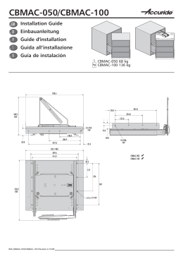
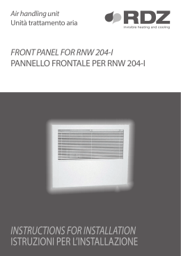
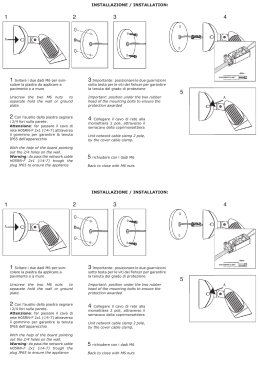
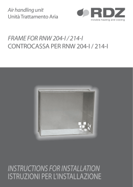
Manuale di installazione, uso e manutenzione Installation, user and maintenance manual Montage-, Benutzungs- und Wartungshandbuch Manuel de montage, utilisation et maintenance GRAZIE per aver scelto MOTOSCENICA® e BETTIO. Dal grande successo di SCENICA®, il reparto ricerca e sviluppo BETTIO crea MOTOSCENICA®, la prima zanzariera ad apertura automatica dotata di motorizzazione di serie. Potente, affidabile ma leggera e sottile, MOTOSCENICA® garantisce un comfort unico perché il motore scelto da BETTIO consente di aprire e chiudere la zanzariera con un semplice tocco della barra maniglia. MOTOSCENICA® dispone inoltre di un’ampia gamma di dispositivi opzionali offrendo una combinazione di ben 7 automazioni diverse. Questi accessori rendono semplice e veloce la movimentazione di zanzariere anche molto grandi, senza alcuno sforzo fisico. Bettio MOTOSCENICA®, tecnologia in movimento. Thank you for your choice of Motoscenica and Bettio From the great success of SCENICA®, BETTIO’s R&D Department realizes MOTOSCENICA®, the first mass-produced flyscreen automatically operated and fully motor equipped. Powerful and affordable, but also light and thin, MOTOSCENICA® ensures an unrivalled comfort because the motor chosen by BETTIO allows to open and close the screen with a simple touch of the handle bar. Moreover MOTOSCENICA® has a wide range of options with a combination of 7 different automations. With these components you will find easy and quick to handle even big screens, without any physical effort. MOTOSCENICA® by BETTIO, technology in motion. NOUS VOUS REMERCIONS d’avoir choisi MOTOSCENICA® et BETTIO. Après le grand succès de SCENICA®, le secteur recherche et développement de BETTIO a créé MOTOSCENICA®, la première moustiquaire à ouverture automatique équipée d’une motorisation de série. Puissante et fiable, de même que légère et fine, MOTOSCENICA® garantit un confort unique car le moteur choisi par BETTIO permet d’ouvrir et de fermer la moustiquaire d’un seul geste sur la barre poignée. MOTOSCENICA® dispose également d’une vaste gamme de dispositifs, en option, offrant une combinaison de bien 7 automations différentes. Ces accessoires rendent le mouvement des moustiquaires, y compris les très grandes, encore plus facile et rapide, sans aucun effort physique. Bettio MOTOSCENICA®, la technologie qui avance. DANKE, dass Sie sich für MOTOSCENICA® und BETTIO entschieden haben. Auf der Grundlage des großen Erfolgs von SCENICA® hat die Forschungs- und Entwicklungsabteilung von BETTIO das erste Fliegengitter mit automatischer Öffnung ausgerüstet mit serienmäßiger Motorisierung geschaffen, das den Namen MOTOSCENICA® trägt. Stark und zuverlässig, gleichzeitig aber leicht und dünn - MOTOSCENICA® garantiert einzigartigen Komfort, denn der von BETTIO ausgewählte Motor macht es möglich, das Fliegengitter durch eine einfache Berührung des Handgriffs zu öffnen und zu schließen. MOTOSCENICA® verfügt darüber hinaus über eine breitgefächerte Palette an optionalen Vorrichtungen und bietet eine Kombination von nicht weniger als 7 verschiedenen Automationen. Dieses Zubehör macht die einfache und schnelle Bewegung von auch sehr großen Fliegengittern ohne jede Kraftanstrengung möglich. Bettio MOTOSCENICA®, Technologie in Bewegung. INDICE CONTENTS INDEX INDEX Automazioni disponibili pg. 10-17 Available Automations pg. 10-17 Automations disponibles pg. 10-17 Verfügbare Automation pg. 10-17 Installazione accessori pg. 18-34 Accessories installation pg. 18-34 Installation accessoires pg. 18-34 Zubehörteile Montage pg. 18-34 ® Motoscenica 1 battente pg. 35-57 ® Motoscenica 2 battenti pg. 58-64 ® Motoscenica 1 battant pg. 35-57 ® Motoscenica 2 battants pg. 58-64 Motoscenica 1 leaf pg. 35-57 Motoscenica 2 leaves pg. 58-64 Sensore - Radiocomando Sensor - Radio control pg. 65-67 pg. 65-67 Sicurezza e normative pg. 68-76 Safety and CE rules pg. 68-76 ® Motoscenica 1 Flügel pg. 35-57 ® ® Motoscenica 2 Flügel pg. 58-64 ® Capteur – Radiocommande Sensor – Funksteuerung pg. 65-67 pg. 65-67 Sécurité et normes CE pg. 68-76 Sicherheit und CE Vorschriften pg. 68-76 27 Schema dei collegamenti A B Wiring diagram 4 B Diagramme des connexions 6x1 A 27 Anschlussplan A B 4x1 0 1 3 A B 4 27 28 B 4 0 0 1 1 3 3 A A B B 4 4 27 27 28 28 3 1 0 4 3 1 1 3 A B 1 1 3 1 A 0 B 0 can A can B 3 1 3 1 A 0 B 0 3 1 0 3 A B 14 0 3 3 A A B B 4 4 27 27 28 6x128 0 1 A 3 3 A can A can B 3 1 B 0 1 4 A 0 4 can 0B 0 1 3 1 A 0 0 B 3 A B A 4x0.25mm L=0,3mt B A 6x1 1 3 0 A1 3 4x1 24 V + 3 3 1 0 4 3 1X 0 3 A B 3 A B 4 4 27 27 28 28 C A 0 4x1 can A 3 A B 1 4 3 0 B 2x2 1 C 2x2 0 3x0.25mm L=4mt can A can B 3 1 3 1 A 0 B 0 0 1 3 4 8 41 0 1 3 4 8 41 BL can B 1 C C 2x2 C 4x0.25mm L=4mt 4x0.25mm L=4mt 0 1 3 4 8 C 0 1 3 4 8 41 BL Display Motore Motor Moteur Motor 0 1 3 4 8 41 BL 2° motore 1 2 3 4 5 Radar attivo Pulsante a sfioramento Toucless sensor 2 moteur Capteur actif Détecteur à effleurement bianco / white / blanc / weiss 2 motor Aktivsensor Berührungsloser Taster rosa pink / roseActive / rosaradar 2nd /motor 1 2 3 4 5 Radar passivo Passive radar Capteur passif Passivsensor marrone / brown / brun / braun Colori dei cavi elettrici wires biancoElectric / white / blanc / weisscolors Couleur des câbles électriques marrone / brown / brun / braun Farbe der elektrischen Leitungen rosa / pink / rose / rosa B 4x0.2 L=0,3 X 4 can A 4x1 0 1 B 3x0.25mm L=4mt X 4 3 11 4x1 4x0.25mm L=0,3mt 0 B 1 3 3B Display can A can B 1 4 0 4 3 0 1 1 0 Motore Motor Moteur 0 0 0 3 4 4 B 28 4 3 3 3 28 giallo / yellow / jaune / gelb rosa / pink / rose / rosa verde / green / verte / grün bianco / white / blanc / weiss grigio / grey / gris / grau marrone / brown / brun / braun giallo / yellow / jaune / gelb giallo / yellow / jaune / gelb COLLEGAMENTI ELETTRICI MOTORE Comandi Comando 3 N.O. 1 Consultare la scheda tecnica allegata per maggiori dettagli. 4 N.O. CHIUSURA La chiusura del contatto attiva la manovra di chiusura. 1 1 3 4 N.O. STOP N.C. SICUREZZA DI INVERSIONE La concomitanza di un comando apre e di un comando chiude effettua l’arresto di qualsiasi movimento. Attenzione: alla riapertura del contatto la zanzariera riprende la manovra interrotta. L’apertura del contatto provoca l’inversione del movimento (riapertura) durante la fase di chiusura. 8 Uscite e accessori Riapertura 1 0 Elettroblocco RER Uscita Valore + - 1 BL 0 1 3 4 8 41BL Radar RER Descrizione La chiusura del contatto attiva la manovra di apertura. 1 41 + Uscita 24 V= / 0,3 A Apertura Chiusura Funzione APERTURA 24 V= / 0,3 A + - LED RER ON TC 1 2 24 V= / 0,5 A Descrizione Alimentazione accessori. Uscita per alimentazione accessori esterni. Dispositivo di blocco OCLOKA. Il blocco viene alimentato solo a zanzariera chiusa. N.B.: in mancanza di alimentazione di rete la zanzariera è sbloccata e può essere mossa manualmente. Radar RER. Consente il collegamento di uno o due radar RER. Attenzione: impostare il dip-switch del radar RER=DX. Trimmer TC Alimentazione 0s 30 s MAX=disabled (Vedi dati tecnici) Tempo di chiusura automatica. Da 0 a 30 s. Regola il tempo che intercorre tra la fine della manovra di apertura e l’inizio della chiusura automatica. Con zanzariera aperta un comando apre rinnova il conteggio. Se si desidera escludere la chiusura automatica, regolare TC al massimo. Segnalazioni LED (bicolore) Verde Rosso Acceso Presenza di alimentazione 24 V=. Sicurezza 41 - 8 aperta. Lampeggiante Anomalia encoder / automazione. Fallimento test sicurezza. 4.5 Dip-Switch Dip-Switch DIP1 DIP2 Descrizione Spinta in chiusura. Mantiene l’anta in posizione di chiusura. Selezione senso di marcia. Il senso di apertura va considerato guardando l’automazione dal lato ispezionabile. Disabilitata. OFF Abilitata. ON Apertura a sinistra per automa- Apertura a destra per automazione ad un’anta. zioni ad un’anta. Selezione per automazioni a due ante. ELECTRICAL CONNECTIONS Commands Command 3 N.O. 1 Refer to the data sheets for more details. Function OPENING Description The opening manoeuvre starts when the contact is closed. 1 4 N.O. CLOSING The closing manoeuvre starts when the contact is closed. 1 1 3 4 N.O. STOP N.C. REVERSAL SAFETY DEVICE The coincidence of an opening and closing command stops all movements. Attention: when the contact opens again the door proceeds with the interrupted manoeuvre. The opening of the contact during the closure manoeuvre causes the movement to invert (re-opening). 8 41 Outputs and accessories + Output 24 V= / 0,3 A Opening Closing 1 0 Re-opening Output Value + - 24 V= / 0,3 A + - 24 V= / 0,5 A Electric lock 1 BL 0 1 3 4 8 41BL Radar RER RER RER LED Description Accessories power supply. Power supply output for external accessories. Blocking device (OCLOKA). Blocking is only activated when the door is closed. Note: the door is released in the event of power failure and can be manually operated. RER Radar. Allows the connection of one or two RER radar. Attention: set the radar dip/switch RER=DX. Trimmer ON TC TC 1 2 0s 30 s MAX=disabled Automatic closing time. From 0 to 30 s. Adjust the time that passes between the end of the opening manoeuvre and the start of the automatic closing manoeuvre. The count is reset when an opening command is given with the door open. Adjust the TC to the maximum if automatic closing is not required. Signals Power supply (See technical data) LED (two-color) Green Red ON 24 V= power supply. Safety contact 41 - 8 open. Flashing Encoder/automation fault. Safety test failure. Dip-Switches DIP1 DIP2 Description OFF ON Closure thrust. Disabled. Enabled. Maintain the door wing in the closure position. Left-hand opening for single door Right-hand opening for single Direction selection. door wing automations The opening direction is intended by viewing the wing automations. Selection for double door wing automation from the side being examined. automations. RACCORDEMENTS ÉLECTRIQUES 4.1 Commandes 1 Consultez les fiches pour plus de détails. Commande 3 N.O. 4 N.O. FERMETURE La fermeture du contact active la manoeuvre de fermeture. 1 1 3 4 N.O. STOP La concomitance d’une commande ouvrir et d’une commande fermer provoque l’arrêt de n’importe quel mouvement. Attention: lorsque le contact se rouvrir la porte recommence la manoeuvre interrompue. N.C. SECURITE D’INVERSION L’ouverture du contact provoque l’inversion du mouvement (réouverture) pendant la phase de fermeture. 1 0 Bloc électrique Sortie 1 BL 0 1 3 4 8 41BL RER 8 4.2 Sorties et accessoires Réouverture Radar RER Description La fermeture du contact active la manoeuvre d’ouverture. 1 41 + Courant de sortie 24 V= / 0,3 A Ouverture Fermeture Fonction OUVERTURE Valeur + - 24 V= / 0,3 A + - 24 V= / 0,5 A RER LED Description Alimentation des accessoires. Sortie pour alimentation accessoires externes. Dispositif de verrouillage (OCLOKA). Le verrouillage n’est alimenté que lorsque la porte est fermée. Remarque: si la tension est coupée, la porte est débloquée et on peut l’ouvrir à la main. Radar RER. Permet le raccordement d’un ou de deux radars RER. Attention: programmer le commutateur du radar RER=DX. 4.3 Trimmer ON TC Source de courant (Voir les caractéristiques techniques) TC 1 2 0s 30 s MAX=disabled Temps de fermeture automatique.De 0 à 30 s. Règle le temps qui s’écoule entre la fin de la manoeuvred’ouvertureetledébutdelafermetureautomatique.Aveclaporteouverteunecommandeouvrir fait repartir le comptage. Si l’on veut exclure la fermeture automatique, régler TC sur le maximum. 4.4 Signalisations LED (bicolore) Vert Rouge Allumé Présence de tension 24 V=. Sécurité 41 - 8 ouverte. Clignotant Anomalie encodeur/ automatisme. Echec test sécurité. 4.5 Dip-Switch DIP1 DIP2 Description Poussée en fermeture. Garde le vantail en position de fermeture. Sélection du sens de la marche. Le sens de l’ouverture doit être considéré en regardant l’automatisme de la partie qui peut être inspectionnée. Désactivée. OFF Activé. ON Ouverture à gauche pour automa- Ouverture à droite pour automatismes à un vantail. tismes à un vantail. Sélections pour automatismes à deux vantaux. ELEKTRISCHE ANSCHLÜSSE Befehle Befehl 3 N.O. Funktion ÖFFNUNG Beschreibung Die Schließung des Kontakts aktiviert die Öffnung. 1 4 N.O. SCHLIEßUNG Die Schließung des Kontakts aktiviert den Schließvorgang. 1 1 3 4 N.O. STOPP N.C. UMKEHRSICHERHEIT Wenn gleichzeitig ein Öffnungs- und ein Schließbefehl gegeben wird, wird das Anhalten jeglicher Bewegung ausgelöst. Achtung: Beim erneuten Öffnung des Kontaktes nimmt das Tor wieder die unterbrochene Bewegung auf. Die Öffnung des Kontaktes löst die Umkehr der Bewegung (erneute Öffnung) während der Schließphase aus. 1 Wenden Sie sich an die Datenblätter für weitere Informationen angebracht. 41 + Output 24 V= / 0,3 A Eröffnung Schliessen Ausgänge und Zubehör Ausgang 1 + 0 - Wiedereröffnung Elektroblock 1 BL 0 1 3 4 8 41BL Radar RER RER 8 Wert 24 V= / 0,3 A + - 24 V= / 0,5 A RER LED Beschreibung Stromversorgung des Zubehörs. Ausgang für Stromversorgung des Außenzubehörs. Sperrvorrichtung (OCLOKA). Die Sperre wird nur bei geschlossener Tür mit Strom versorgt. Anm.: Bei mangelnder Stromversorgung ist die Tür entriegelt und kann von Hand bewegt werden. Radar RER. Ermöglicht den Anschluss von einer oder zwei Radareinrichtungen RER. Achtung: Den Dip-Switch des Radars auf RER=DX stellen Trimmer ON TC TC 1 2 0s 30 s MAX=disabled Elektrische Versorgungs (Siehe technische Daten) Zeit der automatischen Schließung. Von 0 bis 30 s. Reguliert die Zeit, die zwischen dem Ende des Öffnungsmanövers und dem Beginn der automatischen Schließung vergeht. Bei geöffnetem Tor beginnt ein Öffnungsbefehl erneut mit der Zählung. Wenn man die automatische Schließung ausschließen möchte, muss TC auf den Höchstwert eingestellt werden. Anzeigen LED (zweifarbig) Grün Rot Leuchtet Stromversorgung vorhanden 24 V=. Sicherheit 41 - 8 geöffnet. Blinkt Störung Encoder / Antrieb. Sicherheitstest misslungen. Dip-Switch DIP1 DIP2 Beschreibung Drücken bei Schließung. Hält den Flügel in Schließstellung. Wahl der Laufrichtung. Die Laufrichtung muss berücksichtigt werden, indem man den Antrieb von der Inspektionsseite aus betrachtet. Deaktiviert. OFF Aktiviert. ON Öffnung nach links für Antriebe Öffnung nach rechts für Antriebe mit einem Flügel. mit einem Flügel. Wahl für Antriebe mit zwei Flügeln. Carter Motore e guida - Motor casement and guide - Caisson moteur et guide - Motorkasten und Führungsschiene misura finita F misuraI incasso misura finita 10* 66 Sezione verticale - Vertical section Section verticale - Vertikale Sektion Sezione orizzontale versione ad un battente - One leaf horizontal section Section horizontale à un battant - Horizontale Sektion (Ein Flügel) misura incasso ESTERNO ESTERNO 74 6666 1010 125 5050 46 9 9 50 50 5555 +8 +8 min 50mm INTERNOINTERNO * Carter Motore ispezionabile: Prevedere listello di copertura - Provide cover strip - Fournir bande de couverture - Geben Abdeckleiste per consentire l’apertura della aletta di ispezione prevedere una distanza minima tra carter e serramento di 10mm. Sezione orizzontale versione a due battenti - Two leaves horizontal section F I misura incasso 50 9 9 Laissez au moins 10 mm d’espace entre le caisson du moteur et la fenêtre pour l’ouverture de l’ailette d’inspection. * Besichtigung des Motorkasten: 50 77 50 I misura finita misura finita ESTERNO INT F misura finita Leave at least 10mm of space between the motor casement and the window for the inspection wing to open. INT EST misura incasso casement: * Caisson du moteur inspectionable: EST Section horizontale à deux battants -Horizontale Sektion (Zwei Flügel) * Inpectionable motor misura incasso Regolatore 125 125 +8 50 Lassen Sie mindestens 10 mm Platz zwischen dem Motorkasten und des Fensters. INTERNO min 70mm F= Misura finita / finished measure / mesure finie / Fertiges Mass I= Misura incasso / recessed measure / mesure à encastrer / Einbaumass Automazioni disponibili Available Automations Automations disponibles Verfügbare Automation Motore Motor Moteur Motor Ricevitore Receiver Récepteur Empfänger Radiocommando Radio control Radio commande Funksteuerung Display Display Display Display Automazione Automation *Grado di protezione: IP20 *Degree of protection: IP20 *Degré de protection: IP20 *Schutzgrad: IP20 M R 52 53 Sensore Sensor Capteur Sensor 56 A* ● B* ● ● ● ● C* ● ● ● ● ● D* ● ● ● ● ● (x2) E* ● ● ● ● F* ● ● ● ● ● (x2) G* ● ● ● ● ● Il presente manuale di installazione è rivolto esclusivamente a personale professionalmente competente. L’installazione, i collegamenti elettrici e le regolazioni devono essere effettuati nell’osservanza della Buona Tecnica e in ottemperanza alle norme vigenti. 10 55 Pulsante a sfioramento Touchless sensor Détecteur avec commande à effleurement Berührungslose Taste Automazioni disponibili Available automations Automations disponibles Verfügbare Automation This installation manual is only addressed to qualified professionals. The installation, electrical connections and adjustments must be made of good workmanship and in accordance with current regulations. Le présent manuel d’installation est destiné exclusivement à un personnel professionnel compétent. La mise en place, les branchements électriques et les réglages doivent être effectués dans les règles de l’art et de la technique et dans le respect des normes en vigueur. ● ● Diese Installationsanleitung richtet sich ausschließlich an qualifiziertes Fachpersonal. Die Installation, die elektrischen Anschlüsse und die Einstellungen müssen unter Beachtung der geltenden Vorschriften fachgerecht ausgeführt werden. Automazione A Automation A M 220V M Si consiglia l’installazione di un interruttore generale a monte della linea di alimentazione. We suggest you to install a general switch at the source of the power supply. M 220V Il est recommandé de monter un interrupteur général en amont de la ligne d’alimentation. Es wird empfohlen, einen der Speiseleitung vorgeschalteten Hauptschalter zu installieren. Automazioni disponibili Available automations Automations disponibles Verfügbare Automation 11 Automazione B Automation B M M R R 52 52 Si consiglia l’installazione di un interruttore generale a monte della linea di alimentazione. We suggest you to install a general switch at the source of the power supply. Il est recommandé de monter un interrupteur général en amont de la ligne d’alimentation. 220V Es wird empfohlen, einen der Speiseleitung vorgeschalteten Hauptschalter zu installieren. M 12 Automazioni disponibili Available automations Automations disponibles Verfügbare Automation R 55 52 220V Automazione C Automation C 220V M M R R 56 52 56 52 Si consiglia l’installazione di un interruttore generale a monte della linea di alimentazione. We suggest you to install a general switch at the source of the power supply. Il est recommandé de monter un interrupteur général en amont de la ligne d’alimentation. 220V Es wird empfohlen, einen der Speiseleitung vorgeschalteten Hauptschalter zu installieren. M R 55 52 56 Automazioni disponibili Available automations Automations disponibles Verfügbare Automation 13 Automazione D Automation D M 220V R M R 52 56 56 56 56 Si consiglia l’installazione di un interruttore generale a monte della linea di alimentazione. 52 We suggest you to install a general switch at the source of the power supply. Il est recommandé de monter un interrupteur général en amont de la ligne d’alimentation. Es wird empfohlen, einen der Speiseleitung vorgeschalteten Hauptschalter zu installieren. 14 Automazioni disponibili Available automations Automations disponibles Verfügbare Automation 220V M R 55 52 56 x2 Automazione E Automation E 220V M 220V R 52 52 53 R M 53 Si consiglia l’installazione di un interruttore generale a monte della linea di alimentazione. We suggest you to install a general switch at the source of the power supply. M R 55 52 53 Il est recommandé de monter un interrupteur général en amont de la ligne d’alimentation. Es wird empfohlen, einen der Speiseleitung vorgeschalteten Hauptschalter zu installieren. Automazioni disponibili Available automations Automations disponibles Verfügbare Automation 15 Automazione F Automation F 220V M 220V R 52 52 53 53 R M 53 53 Si consiglia l’installazione di un interruttore generale a monte della linea di alimentazione. We suggest you to install a general switch at the source of the power supply. Il est recommandé de monter un interrupteur général en amont de la ligne d’alimentation. Es wird empfohlen, einen der Speiseleitung vorgeschalteten Hauptschalter zu installieren. 16 Automazioni disponibili Available automations Automations disponibles Verfügbare Automation M R 55 52 53 x2 Automazione G Automation G Si consiglia l’installazione di un interruttore generale a monte della linea di alimentazione. We suggest you to install a general switch at the source of the power supply. 220V Il est recommandé de monter un interrupteur général en amont de la ligne d’alimentation. M Es wird empfohlen, einen der Speiseleitung vorgeschalteten Hauptschalter zu installieren. 220V 56 R 52 52 R 53 56 M 53 M R 55 52 53 56 Automazioni disponibili Available automations Automations disponibles Verfügbare Automation 17 Installazione accessori Accessories installation Installation accessoires Zubehörteilemontage Prima di montare l’automazione a muro è necessario installare tutti gli accessori ad essa associati. Before installing the wall automation you have to set up all its components. Avant de monter l’automation sur le mur, il est nécessaire de mettre en place tous les accessoires qui lui sont associés. Vor der Montage der Automation an der Wand müssen alle zugehörigen Zubehörteile installiert werden. 18 Installazione accessori Accessories installation Zubehörteilemontage Accessories installation 51 50 Smontare il Carter motore n51. Dismantle the motor adjuster profile n.51. Démonter le Carter moteur n.51. Das Motorgehäuseprofil Nr. 51 ausbauen. Installazione accessori Accessories installation Zubehörteilemontage Accessories installation 19 Prima d’installare l’automazione alla parete, smontare il Ricevitore (R) per collegare gli accessori. Operazione non necessaria per l’Automazione A. Dismantle the receiver (R) to connect the accesories before the installation of the motor adjuster profile on the wall. Operation not required for the Automation A. Avant d’installer l’automation sur le mur, démonter le Récepteur (R) pour brancher les accessoires. Opération non nécessaire pour l’Automation A. R 20 Installazione accessori Accessories installation Zubehörteilemontage Accessories installation Vor der Installation der Automation an der Wand den Empfänger (R) ausbauen, um die Zubehörteile anzuschließen. Dieser Arbeitsschritt ist für die Automation A nicht notwendig. R Installazione accessori Accessories installation Zubehörteilemontage Accessories installation 21 Tasto PRG PRG button Bouton PRG Taste PRG LED Collegamenti motori Motor connections Raccordements moteurs Motoranschlüsse Collegamenti Display Display connection Raccordements display Displayanschlüsse R 22 Installazione accessori Accessories installation Zubehörteilemontage Accessories installation Collegamenti accessori Accessories connections Raccordements accessoires Zubehörteilanschlüsse Display Display Display Display Ø 10mm Ø 3mm 50 Individuare la posizione desiderata e forare usando lo schema in dotazione. Prestare la massima attenzione a non forare i meccanismi all’interno del Carter motore n.50! Choose the desired position and drill following the supplied scheme. Pay attention not to damage the internal mechanisms while drilling! Choisir la position désirée et percer en utilisant le schéma fourni en dotation. Faire extrêmement attention à ne pas percer les mécanismes situés à l’intérieur du Carter moteur n. 50 ! Die gewünschte Position auswählen und unter Benutzung der mitgelieferten Schablone die Bohrungen vornehmen. Sorgfältig darauf achten, nicht die Mechanismen im Motorgehäuse Nr. 50 Installazione accessori anzubohren! Accessories installation Zubehörteilemontage Accessories installation 23 R 24 Installazione accessori Accessories installation Zubehörteilemontage Accessories installation 52 50 Installazione accessori Accessories installation Zubehörteilemontage Accessories installation 25 Inserire il cavo di collegamento e montare il meccanismo interno del display usando le viti in dotazione. Install the internal mechanism by using the supplied screws. Introduire le câble de liaison et monter le mécanisme interne du display en utilisant les vis fournies. Das Anschlusskabel einführen und den internen Mechanismus des Displays mit den mitgelieferten Schrauben montieren. 26 Installazione accessori Accessories installation Zubehörteilemontage Accessories installation C L AC K ! Installazione accessori Accessories installation Zubehörteilemontage Accessories installation 27 PRESTARE PARTICOLARE ATTENZIONE AL SENSO DI INSERIMENTO DEI CAVI INSERT CABLES TO THE RIGHT DIRECTION INSÉRER LES CABLES DANS LE SENS CORRECT AUFNEHMEN SIE DIE KABEL IN DER RICHTIGEN RICHTUNG PRESTARE PARTICOLARE ATTENZIONE AL SENSO DI INSERIMENTO DEI CAVI INSERT CABLES TO THE RIGHT DIRECTION INSÉRER LES CABLES DANS LE SENS CORRECT AUFNEHMEN SIE DIE KABEL IN DER RICHTIGEN RICHTUNG 28 Installazione accessori Accessories installation Zubehörteilemontage Accessories installation 53 56 Si possono collegare fino a 4 dispositivi diversi (vedi esempio).I dispositivi collegati al Canale B possono essere disattivati dal telecomando in dotazione. Il est possible de brancher jusqu’à 4 dispositifs différents (voir l’exemple). Les dispositifs branchés sur le Canal B peuvent être désactivés avec la radio commande fournie en dotation. You can connect up to 4 different devices (see example). The devices connected to Channel B can be disconnected with the remote control. Es können bis zu 4 verschiede Vorrichtungen angeschlossen werden (siehe Beispiel). Die an den Kanal B angeschlossenen Vorrichtungen können über die mitgelieferte Funksteuerung ausgeschaltet werden. Installazione accessori Accessories installation Zubehörteilemontage Accessories installation 29 Sensore - Sensor Capteur - Sensor Individuare la posizione desiderata e forare usando lo schema in dotazione. Prestare la massima attenzione a non forare i meccanismi all’interno del Carter motore n.50! Choose the desired position and drill following the supplied scheme. Pay attention not to damage the internal mechanisms while drilling! Choisir la position désirée et percer en utilisant le schéma fourni en dotation. Faire extrêmement attention à ne pas percer les mécanismes situés à l’intérieur du Carter moteur n. 50 ! Die gewünschte Position auswählen und untr Benutzung der mitgelieferten Schablone die Bohrungen vornehmen. Sorgfältig darauf achten, nicht die Mechanismen im Motorgehäuse Nr. 50 anzubohren! 30 Installazione accessori Accessories installation Zubehörteilemontage Accessories installation Ø 8mm Ø 3,4mm 56 Installazione accessori Accessories installation Zubehörteilemontage Accessories installation 31 Montare il meccanismo interno del sensore usando le viti in dotazione. Install the sensor’s internal mechanism by using the supplied screws. Monter le mécanisme interne en utilisant les vis fournies pour cela. Den internen Mechanismus des Sensors mit den mitgelieferten Schrauben montieren. 32 Installazione accessori Accessories installation Zubehörteilemontage Accessories installation C L AC K ! Installazione accessori Accessories installation Zubehörteilemontage Accessories installation 33 C L AC K ! 34 Installazione accessori Accessories installation Zubehörteilemontage Accessories installation Pulsante a sfioramento Touchless sensor Détecteur à effleurement Berührungslose Taste 1 1 2 3 4 5 TS 2 EN 53 8 3 98 9 Schema cablaggio per colore Wiring scheme by color Schéma de câblage par la couleur Verdrahtungsschema durch Farbe 3 1 4 5 4 5 Fig. 2 Fig. 2 6 76 7 Fig. 3 Fig. 3 2 3 4 Fig. 4 Fig. 4 1. Riferimenti (Fig. 1-2-3) 1. Riferimenti (Fig. 1-2-3) 1. Mascherina 1.Template 1. Support 1. Frontrahmen [1] Mascherina [6]2.Regolatore sensibilità 2. Lente 2. Lens Lentillesensibilità 2. Linse [1] Mascherina [6] Regolatore 3. Jumper selezione portata [2] Lente 3. Range selecting jumper 3.Trasmettitore Cavalier portées de détection 3. Jumper Reichweiteneinstellung [7] [2] Lente [7] Trasmettitore 4. Morsettiera 4. Terminal board 4. Borne de connexion 4. Anschlussklemmen [3] Jumper selezione portata [8] Ricevitore Jumper selezione portata 5. Jumper modalità [3] rilevamento 5. Reading mode jumper [8] Ricevitore 5. Cavalier mode de détection 5. Jumper für Erfassungsfunktion [4] Morsettiera segnalazione funzionamento 6. Regolatore sensibilità 6. Threshold regulator 6.Led Régulateur de sensibilité 6. Empfindlichkeits-Einstellung [4] Morsettiera [9] Led[9] segnalazione funzionamento 7. Trasmettitore 7. Transmitter 7. Emetteur 7. Sender [5] Jumper modalità rilevamento [5] Jumper modalità rilevamento 8. Ricevitore 8. Receiver 8. Récepteur 8. Empfänger 9. Led segnalazione2. funzionamento 9. Function led 9. Led indicateur de fonction 9. LED Funktionsanzeige 2. Installazione Installazione Fig. 5 4) Montaggio in scatola da incasso (Fig. 4)(Fig. Montaggio in scatola da incasso a muro.a muro. (Fig. 5) Montaggio con scatola da esterno. (Fig. 5) Montaggio con scatola da esterno. Importante: all’accensione, evitare di collocare nell’area di Importante: all’accensione, evitare di collocare oggettioggetti nell’area di Installazione accessori Accessories installation Zubehörteilemontage Accessories installation 35 53 53 36 Installazione accessori Accessories installation Zubehörteilemontage Accessories installation Installazione a parete. Installazione in scatola. Wall mounting. Box mounting. Assemblage au mur Assemblage en boîte Wandmontage Montage in externe Abzweigdose Versione ad un battente One leaf version F R M E G 50 F H C 51 E D M. Motore R. Ricevitore C. Staffa compensatore D. Staffa puleggia E. Compensatore F. Reggicavo G. Cinghia di trasmissione H. Staffa cinghia M. Motor R. Receiver C. Adjuster bracket D. Pulley bracket E. Adjuster F. Cable holder G. Transmission Belt H. Belt bracket M. Moteur R. Récepteur C. Bride du régulateur D. Bride de la poulie E. Régulateur F. Support du câble G. Courroie H. Bride de la courroie M. Motor R.Empfänger C. Ausgleichsbügel D. Scheibenbügel E. Ausgleicher F. Kabelhalter G. Riemen H. Bügelriemen Installazione 1 battente One leaf installation Installation 1 battant 1 Flügel Installation 37 50 51 62 56 61 53 54 55 57 58 50. Carter motore 1 51. Carter motore 2 52. Display 53. Pulsante a sfioramento con cavo 54. Cuffie per guida 55. Radiocomando con supporto 56. Sensore attivo con cavo 57. Viti per staffa cinghia 58. Tasselli per compensatore 59. Coprivite barra maniglia 60. Supporti tasselli per compensatore 61. Dima di foratura lato cassonetto 62. Dima di foratura lato opposto al cassonetto. 59 60 52 50. Motor adjuster profile 1 51. Motor adjuster profile 2 52. Display 53. Wired touchless sensor 54. Track side caps 55. Remote control with support 56. Wired active sensor 57. Screws for transmission belt bracket 58. Wall plugs for adjuster 59. Screw cover for handle bar 60. Wall plug supports for adjuster 61. Box side drilling template 62. Opposite box side drilling template 50. Carter moteur 1 51. Carter moteur 2 52. Display 53. Détecteur avec commande à effleurement avec câble 54. Coiffe pour guide 55. Radio commande avec support 56. Capteur actif avec câble 57. Vis pour bride courroie 58. Tasseaux pour adaptateur 59. Bouchon couvre-trou pour barre poignée 60. Supports pour tasseaux adaptateur 61. Gabarit pour côté caisson 62. Gabarit pour côté opposé caisson 50. Motorgehäuse 1 51. Motorgehäuse 2 52. Display mit Kabel 53. Berührungsloser Taster mit Kabel 54. Führungsschienenhaube 55. Funksteuerung mit Träger 56. Aktivsensor mit Kabel 57. Riemensbügelsschrauben 58. Ausgleichsdübel 59. Griffleistebohrungsabdeck 60. Träger für Ausgleichsdübel 61. Schablone für Kastenseite 62. Schablone für Gegenteilkastenseite Predisporre sul lato opposto al cassonetto la canalina per le connessioni elettriche all’interno dell’area tratteggiata. Cavo alimentazione: 3x1,5mm2 Cavo sensori: diametro 5mm Arrange the raceway within the traced area for the electric connections on the side opposite to the box. Wire for power supply: 3x1,5mm² sensor wire: 5mm diameter Poser la goulotte technique, prévue pour les connexions électriques, du côté opposé au caisson, à l’intérieur de la zone pointillée. Câble d’alimentation : 3x1,5 mm2 Câble pour les capteurs : diamètre 5 mm Auf der dem Kasten gegenüberliegenden Seite den Kanal für die elektrischen Anschlüsse innerhalb des schraffierten Bereichs vorsehen. Speisekabel: 3 x 1,5 mm2 Sensorkabel: Durchmesser 5 mm Installazione 1 battente One leaf installation Installation 1 battant 1 Flügel Installation 39 Lato cassonetto. Box side. Côté caisson. 40 Installazione 1 battente One leaf installation Installation 1 battant 1 Flügel Installation Kastenseite Lato opposto al cassonetto. Opposite box side. Côté opposé caisson. Gegenteilkastenseit. Installazione 1 battente One leaf installation Installation 1 battant 1 Flügel Installation 41 Ø 9mm 42 Installazione 1 battente One leaf installation Installation 1 battant 1 Flügel Installation 58 Installazione 1 battente One leaf installation Installation 1 battant 1 Flügel Installation 43 58 50 44 Installazione 1 battente One leaf installation Installation 1 battant 1 Flügel Installation Attenzione! La superficie di appoggio deve essere perfettamente piana e parallela al pavimento. Attention ! La surface d’appui doit être parfaitement plane et parallèle au sol. Attention! The leaning area must be perfectly smooth and parallel to the floor. Achtung! Die Auflagefläche muss perfekt eben und parallel zum Boden sein. 58 60 Installazione 1 battente One leaf installation Installation 1 battant 1 Flügel Installation 45 46 Installazione 1 battente One leaf installation Installation 1 battant 1 Flügel Installation Alimentare l’automazione per accertarsi del corretto funzionamento dei componenti elettrici. 55 52 Power the automation to ensure the proper functioning of the electrical components. Alimenter l’appareil pour contrôler le parfait fonctionnement des composants électriques. Die Automation mit Strom versorgen, um sicherzustellen, dass die elektrischen Bauteile richtig funktionieren. 53 56 220V Installazione 1 battente One leaf installation Installation 1 battant 1 Flügel Installation 47 14 Seguire le istruzioni di montaggio del modello di zanzariera scelto: Per Scenica® dalla pg. 9 del libretto istruzioni. Per Scenikit® dalla pg. 11 del libretto istruzioni. Follow the instructions of the model you have chosen: For Scenica® from page 9 of the instructions manual. For Scenikit® from page 11 of the instructions manual. Suivre les instructions de montage du modèle de moustiquaire choisi : Pour Scenica® à partir de la page 9 du livret d’instructions. Per Scenikit® à partir de la page 11 du livret d’instructions. 14 48 Installazione 1 battente One leaf installation Installation 1 battant 1 Flügel Installation Die Montageanleitung des ausgewählten Fliegengittermodells befolgen: Für Scenica® ab S. 9 der Anleitung. Für Scenikit® ab S. 11 der Anleitung. 50 51 Installazione 1 battente One leaf installation Installation 1 battant 1 Flügel Installation 49 50 51 50 Installazione 1 battente One leaf installation Installation 1 battant 1 Flügel Installation Spingere il Carter motore n.51 in corrispondenza dei compensatori. Pousser le Carter moteur n. 51 au niveau des éléments de compensation. Push the motor adjuster profile n.51 next to the adjusters. Das Motorgehäuseprofil Nr. 51 an den Ausgleichern andrücken. 50 E C L AC K ! 51 C L AC K ! E Installazione 1 battente One leaf installation Installation 1 battant 1 Flügel Installation 51 52 Installazione accessori Accessories installation Zubehörteilemontage Accessories installation Riportare la barra maniglia fino al cassonetto per poterla collegare alla staffa della cinghia. Bring back the handle bar next to the box for connecting the strap holder. Ramener la barre poignée jusqu’au caisson afin de pouvoir la relier à la bride de la courroie. Den Handgriff bis zum Kasten führen, um ihn an den Riemenbügel anschließen zu können. Installazione accessori Accessories installation Zubehörteilemontage Accessories installation 53 Allineare le battute della staffa con il bordo inferiore del carter motore n.51. Line up the bracket’s bevels with the lower edge of the motor adjuster profile n.51. Aligner les butées de la bride avec le bord inférieur du carter moteur n. 51. 54 Installazione 1 battente One leaf installation Installation 1 battant 1 Flügel Installation Die Anschläge des Bügels am unteren Rand des Motorgehäuseprofils Nr. 51 ausrichten. C L AC K ! 57 59 57 Installazione 1 battente One leaf installation Installation 1 battant 1 Flügel Installation 55 54 56 Installazione 1 battente One leaf installation Installation 1 battant 1 Flügel Installation Installazione 1 battente One leaf installation Installation 1 battant 1 Flügel Installation 57 Versione a due battenti Two leaves version M M La versione a due battenti prevede, oltre all’Automazione scelta, una seconda automazione munita di motore e cinghia di trasmissione. Further to the chosen automation, this version provides a second unit with motor and slide belt only. 58 Installazione 2 battenti Two leaves installation Installation 2 battants 2 Flügel Installation En plus de l’automation choisie, la version à deux battants prévoit une deuxième automation équipée d’un moteur et d’une courroie de transmission. Die zweiflüglige Ausführung sieht über die ausgewählte Automation eine zweite Automation mit Motor und Antriebsriemen vor. 220V M Si consiglia di far arrivare la linea elettrica alla mezzeria del vano ed alimentare il primo motore. Il secondo motore va collegato al primo tramite il cavo in dotazione. We suggest you to reach the centre of the frame with the power line and supply the first motor. Connect the second motor to the first with the supplied wire. Spazio alternativo per passaggio cavo elettrico. Alternative space for the electric wire way. Espace alternatif pour le passage du câble électrique. Alternative Stelle für den Durchgang des Elektrokabels. Il est recommandé de faire arriver la ligne électrique au milieu du compartiment et d’alimenter le premier moteur. Le deuxième moteur sera relié au premier au moyen du câble fourni en dotation. Es wird empfohlen, die Stromleitung bis zur Mitte des Rahmens zu führen und den ersten Motor mit Strom zu versorgen. Der zweite Motor wird über das mitgelieferte Kabel an den ersten angeschlossen. Installazione 2 battenti Two leaves installation Installation 2 battants 2 Flügel Installation 59 M 60 Installazione 2 battenti Two leaves installation Installation 2 battants 2 Flügel Installation M M Usare cavi elettrici forniti: n.1 4x0.25 L=0.3m n.1 3x0.25 L=4m (vedere schema pag.4) Use the provided cables: n.1 4x0.25 L=0.3m n.1 3x0.25 L=4m (see wiring scheme pag.4) Utiliser les cordons d’alimentation fournis: n.1 4x0.25 L=0.3m n.1 3x0.25 L=4m (voir schéma page 4 ) Benutzen mitgelieferten Stromkabel: n.1 4x0.25 L=0.3m n.1 3x0.25 L=4m (siehe Grafik Seite 4) Installazione 2 battenti Two leaves installation Installation 2 battants 2 Flügel Installation 61 50 50 Seguire le istruzioni precedenti per ogni battente (pg.32-47) For each leaf follow the previous instructions. (pg.32-47) Suivre les instructions précédentes pour chaque battant (pages 32-47) Für jeden Flügel die vorhergehenden Anweisungen (S. 32 – 47) befolgen. 14 62 Installazione 2 battenti Two leaves installation Installation 2 battants 2 Flügel Installation 14 54 Installazione 2 battenti Two leaves installation Installation 2 battants 2 Flügel Installation 63 Il movimento dei due battenti è sempre sincronizzato, escluso nell’Automazione A. The leaves are always synchronized, except for the automation A. Le déplacement des deux battants est toujours synchronisé, sauf dans le cas de l’automation A. 64 Installazione 2 battenti Two leaves installation Installation 2 battants 2 Flügel Installation Die Bewegung der beiden Flügel ist immer synchronisiert, außer bei Automation A. Manual de instalação para o detector de movimento e presença a raios infraverrmelhos activo 30 63 Montageanleitung Manual de - für Aktiv-Infrarot- instalaciòn Bewegungs- und para detector e Anwesenheitssen- de movimiento sor 1y presencia infrarojos activo 6 36 7 Rilevazione presenza Presencepresenza detection Rilevaz. Détection de présence Presence detection Vorhandenseinwahl Rilevazione movimento Rilevaz. movimento Motion detection 1 Motion detection Détection de mouvement Bewegungswahl 125 43 H 46 A B 2 3 4 C D 5 H A B C D 2200 180 310 750 1300 E 2300 7 2500 200 350 850 1480 2700 220 380 920 1590 200 2600 0 2800 125 43 46 56 H A B C D 2200 180 310 750 1300 E Fig. 2 2300 E 36 7 1 Fig. 1 6 6 2 3 4 5 2500 2700 3000 200 220 250 350 380 410 850 920 1020 1480 1590 1770regolazioni per ottimizzare Eseguire le opportune il2600 rilevamento. 2800 3100 Make the proper adjustments to optimize the Fig. 3 detection. Grigio - Grey Effectuer - Gris - Grau les - Grisréglages - Gris 3000 24 V= 250 410 1020com 1770N.O. Fig. 2 la détection. opportuns afin d’optimiser 0 Grigio - Grey - Gris - Grau - Gris - Gris 1 Für die Optimierung der Erfassung die geeigneten Einstellungen Bianco - White - Blanc - Weiss - Blancovornehmen. - Branco 1 3100 N.C. Fig. 3 Giallo - Yellow - Jaune - Gelb - Amarillo - Amarello 3 Verde - Green - Vert - Grün - Verde - Verde (*) Fig. 4 Sensore - Radiocomando Sensor - Radio control Capteur - Radio commande Sensor - Funksteuerung 65 R Programmazione radiocomando Radio control programming Programmation de la radio commande Funksteuerung Programmierung CLICK! R 1.Premere rapidamente una volta il tasto PRG nella scheda ricevitore. 2.Il led giallo accanto al bottone PRG si accende (luce fissa). 3.Premere rapidamente un tasto del radiocomando: il led lampeggia. 4.Attendere che il led smetta di lampeggiare senza premere tasti del telecomando. 1. Push quickly and once the PRG button receiving card; 2.The yellow led close to the PRG button goes on (fixed light) 3.Push quickly a button of the radio control: the led starts to blink 4.Wait for the led stops blinking without pushing other buttons of the remote control. 1. Appuyer rapidement une seule fois sur la touche PRG située sur la carte du récepteur. 2. La Led jaune située à côté du bouton PRG s’allume (lumière fixe). 3. Appuyer rapidement sur une touche de la radiocommande : la Led clignote. 4. Attendre que la Led cesse de clignoter, sans appuyer sur les touches de la radiocommande. 1.Die Taste PRG auf der Empfängerkarte einmal schnell drücken. 2.Die gelbe Led neben der PRG-Taste schaltet sich ein (dauerleuchtend). 3.Eine Taste der Funksteuerung schnell drücken: Die Led blinkt. 4.Abwarten, dass die Led aufhört zu blinken, ohne andere Tasten der Funksteuerung zu drücken. 66 Sensore - Radiocomando Sensor - Radio control Capteur - Radio commande Sensor - Funksteuerung Tasto Key Touche Taste Descrizione Description Description Beschreibung 1 Apertura zanzariera con chiusura automatica Insect screen opening with automatic closing Ouverture moustiquaire avec fermeture automatique Öffnungsinsektenschutz mit automatischem Verschluß 1 Zanzariera sempre aperta Opened insect screen always Moustiquaire ouverte toujours Immer offener Insektenschutz 2 Chiusura zanzariera Insect screen closing Fermeture moustiquaire Insektenschutzverschluß 2 Zanzariera sempre chiusa (disattivazione sensori) Closed insect screen always (sensors deactivated) Moustiquaire toujours fermé (capteurs désactivé) Immer geschlossen Insektenschutz (Sensoren deaktiviert) 3 Attivazione motore sensori canale A e canale B attivi Motor activation sensors channel A anb B active Activation de moteur capteurs canaux A et B actif Motoransteuerung Sensoransteuerung sensoren Kanäle A anb B aktiv 3 Solo sensori canale A attivi Activated A sensors channel only Canal A capteurs active seulement Nur Aktive A Sensor Känale Visualizzazione display Display visualization Visualisation display Displayvisualisierung 2 3 LEGENDA LEGEND LÉGENDE LEGENDE 15 s 4 Disattivazione automazione ritardata di 30 sec. - Movimentazione manuale Automation deactivation delayed of 30 seconds- Manual handling Désactivation de l'automation retardée des 30 secondes- Mouvement manuel 30 Sekunden verspätete Automationsdeaktivierung - Manuelle Bewegung 15 s 4 Automazione disattivata - Movimentazione manuale Deactivated automation - Manual handling Automation désactivé - Mouvement manuel Deaktivierte Automation - Manuelle Bewegung 4 1 PRESSIONE SEMPLICE DEL TASTO SINGLE PRESSURE OF THE KEY PRESSION SIMPLE DU TOUCHE EINZELNDRUCK DER TASTE PRESSIONE PROLUNGATA DEL TASTO (FINE LAMPEGGIAMENTO LED) PROLONGED PRESSURE OF THE KEY (END LED FLASHING) PRESSION PROLONGÉ DU TOUCHE (FIN CLIGNOTEMENT LED) VERLÄNGERTER DRUCK DER TASTE (ENDE DES LEDBLINKEN) Sensore - Radiocomando Sensor - Radio control Capteur - Radio commande Sensor - Funksteuerung 67 DICHIARAZIONE DI CONFORMITÀ ai sensi della Direttiva Europea 98/37/CE all.II A e 2006/42/CE La società BETTIO Service S.p.A. con sede in Via dell’Artigianato n°9, 30020 Marcon (Venezia), nella persona del Sig. Loris Bettio nella sua qualità di Presidente espressamente delegato a questo scopo e sotto la sua propria esclusiva responsabilità, DICHIARA EN 13561 che la persona autorizzata a costituire il fascicolo tecnico, è l’Ing. Franco Zannoner reperibile presso l’Azienda; che la zanzariera motorizzata con rete in fibra di vetro, nel modello standard MotoScenica®, Laterale senza barriere, in varie misure come specificato nel Catalogo in vigore, È CONFORME ai requisiti delle seguenti Direttive Europee: • 98/37/CE del 22/06/98 (D.P.R. 459/96) • 2006/42/CE • DIR 73/23/CE • EN 13561:2004 “tende da sole” requisiti di funzionamento e sicurezza. Resistenza al vento NPD. • EN 14201:2004 Resistenza alle operazioni ripetute. • EN 13120:2004 Tende tecniche - requisiti di funzionamento e sicurezza. • EN 55014. Compatibilità elettromagnetica. • CEI EN 60204-1 Sicurezza del macchinario. Equipaggiamento elettrico. Regole generali. • CEI EN 60335-1 Sicurezza degli apparecchi d’uso domestico e similare. Norme generali. • CEI EN 60335-2-97 Sicurezza degli apparecchi d’uso domestico e similare. Requisiti particolari per le motorizzazioni delle serrande, tende e apparecchi similari. • UNI EN 349/94 Spazi minimi per evitare lo schiacciamento di parti del corpo. • UNI EN ISO 12100-1/2005, UNI EN ISO 12100-2/2005 Sicurezza del macchinario. Principi generali di progettazione. • UNI EN 1050/98 Principi per la valutazione del rischio. nonchè alle loro modifiche e aggiornamenti ed alle disposizioni che ne attuano il recepimento all’interno dell’Ordinamento Legislativo Nazionale del paese di destinazione e di utilizzo della zanzariera. Firma del delegato BETTIO SERVICE S.p.A. Presidente Loris Bettio 68 Sicurezza e normative Safety and CE rules Règlementation CE CE Vorschriften Marcon (VE), 29 dicembre 2009 ISTRUZIONI D’USO E MANUTENZIONE (ISTRUZIONI ORIGINALI) 1. SCOPO Queste istruzioni sono rivolte a chi utilizza la zanzariera o la tenda come installatore, manutentore, proprietario o utente. Con questo strumento la BETTIO SERVICE SPA intende fornire al Cliente uno strumento di supporto per un uso più consapevole e corretto dei sistemi di zanzariere e tende filtranti o oscuranti installati, al fine di un’ottimizzazione delle loro prestazioni. E’ quindi consigliato per un corretto e vantaggioso utilizzo del sistema tenere disponibili le presenti note ai fini di garantire una rapida consultazione ogni qualvolta le circostanze lo rendano necessario. Esse sono comunque supportate dal Manuale d’Uso e Manutenzione e dal Fascicolo Tecnico disponibili in Azienda. 2. CAMPO DI APPLICAZIONE Le presenti istruzioni si riferiscono ai seguenti modelli: Scenica®, Laterale senza barriere 50 - Scenica®Incasso, Laterale incasso senza barriere 50 - MiniScenica®, Laterale senza barriere 40 - MiniScenica®Incasso, Laterale incasso senza barriere 40 - PicoScenica®, Laterale senza barriere 25 - Motoscenica®, Laterale motorizzata senza barriere - Motoscenica®Incasso, Laterale Incasso motorizzata senza barriere - Moovica, Verticale motorizzata - Moovicaincasso, Verticale motorizzata incasso - Fox, Molla incasso 46 mm - Delta, Molla clic-clak incasso 50 mm - Sigma, Catena clic-clak incasso 50 mm - Omega, Laterale incasso 50 mm - Zeta, Molla incasso 40 mm - Kappa, Laterale incasso 40 mm con calamita – India, Incasso 50 mm – Africa, Catena incasso 50 mm - Sonia, Molla tradizionale - Katia, Catena tradizionale - Alba, Molla cuffie telescopiche e cassone quadrato - Lisa, Laterale cuffie telescopiche e cassone quadrato - Alfa, Molla cassone raggiato con cuffie telescopiche - Clever, Molla con cuffie ad inesto rapido - Beta, Laterale cuffie telescopiche e cassone raggiato - Gamma, Catena clic-clak® telescopica cassone raggiato – Rosy, Molla frizionata clic-clak® cuffie e guide telescopiche - Giudy, Catena clic-clak® cuffie e guide telescopiche - Mini, Molla 31 con guida antivento- Flash, Laterale calamita 31 con guida antivento – RevoluxbyBettio, clic-clak® 40 con antivento - Telaio fisso, Fissi - Elena, Saliscendi – Laura, Scorrevole – Maya, Scorrevole senza guide a pavimento - Alice, Porta a battente con molla di ritorno – Sabbia, 41 a molla – Acqua, 33 a molla – Terra, 41 a catena – Aria, 33 a catena, per i quali sono coerentemente adattati i contenuti. 3. RIFERIMENTI Le presenti istruzioni, sono state redatte tenendo conto delle normali condizioni di uso della macchina al fine di informare, unitamente alle altre istruzioni per l’uso apposte sulla macchina, gli operatori/utilizzatori anche sui rischi residui che la stessa presenta. 4. USI PREVISTI La funzione del sistema zanzariera installato è esclusivamente quella di dare protezione contro l’intrusione di insetti e piccoli animali negli ambienti da proteggere, mentre la funzione dei sistemi filtranti e oscuranti è esclusivamente quella di filtrare od oscurare un determinato ambiente dalla luce diurna. Ogni impiego diverso da quello indicato deve essere considerato improprio, e pertanto vietato, in quanto le relative condizioni di esercizio non sono state considerate nell’ analisi dei rischi condotta dal fabbricante e per i quali potrebbero non essere presenti protezioni specifiche. E’ vietato appoggiarsi alla rete o al tessuto. E’ vietato lasciare la barra maniglia senza accompagnarla fino al totale riavvolgimento della rete o del tessuto. Quando la velocità del vento raggiunge i 20 km/h è necessario chiudere la zanzariera o la tenda. L’uso improprio assolve da ogni responsabilità il costruttore stesso, per eventuali danni causati a persone o cose. Il mancato rispetto delle condizioni d’uso fa decadere automaticamente qualsiasi tipo di garanzia data dal produttore. 5. REQUISITI DELL’ OPERATORE L’uso normale della zanzariera e della tenda filtrante o oscurante, è consentito ad operatori non professionisti purchè di età superiore ad anni 12. Le operazioni di installazione, riparazione e manutenzione straordinaria, devono essere effettuate da personale tecnico qualificato. 6. RACCOMANDAZIONI PER L’INSTALLAZIONE L’installazione deve essere eseguita nel pieno rispetto del D.Lgs. 81/2008 e delle successive modifiche e integrazioni, per tutto ciò che attiene la sicurezza delle persone. Sicurezza e normative Safety and CE rules Règlementation CE CE Vorschriften 69 Il committente e l’installatore sono rispettivamente responsabili ai sensi della legge vigente, in materia di sicurezza. E’ necessario controllare, prima dell’utilizzo, che trabattelli, ponteggi, scale e tutti i dispositivi di protezione individuale (imbracature, cinghie di sicurezza, guanti, scarpe di sicurezza, elmetti, ecc.), eventualmente utilizzati, siano a norma ed in buono stato. Utilizzare i mezzi d’imbracatura adeguati. Nel caso gli installatori siano più di uno, è necessario coordinare i lavori, definire i compiti e le responsabilità. Gli operatori devono comportarsi in conformità alle istruzioni di sicurezza ricevute (POS). Nel caso in cui il prodotto debba essere montato ad un piano elevato rispetto a quello di terra, è necessario delimitare e presidiare l’area durante la salita al piano del prodotto in modo che nessuno possa trovarsi sotto l’eventuale carico sospeso. L’imballo del prodotto contiene le istruzioni di montaggio, d’uso, manutenzione e garanzia: l’installatore deve accertarsi che siano consegnate, previa lettura e commento, all’utilizzatore finale. 7. INSTALLAZIONE DELLA STRUTTURA MECCANICA Una installazione non corretta può essere causa di infortuni alle persone. Leggere attentamente le istruzioni per un fissaggio corretto del prodotto in modo da evitare rischi di caduta dello stesso. E’ necessario verificare lo stato della struttura sulla quale viene effettuato l’ancoraggio/fissaggio della zanzariera o della tenda. In realtà lo sforzo dinamico cui il telaio dovrà resistere con la zanzariera completamente svolta dal cassonetto, è quello del vento che soffia a 130 km/h. La tenda oscurante o filtrante può essere installata sul muro o sul serramento: la scelta dei tasselli di ancoraggio per l’installazione sul muro e delle viti di fissaggio per l’installazione sul serramento, è dipendente dal tipo e dallo stato del muro o del serramento. Installazione della tenda oscurante o filtrante sul muro: per il fissaggio delle testate e dei piedini inferiori si consiglia di usare viti a testa cilindrica con impronta a croce da 3x30 mm con tassello in nylon Euro 4, mentre per il fissaggio delle guide si consiglia di usare viti a testa cilindrica con impronta a croce da 4x40 mm con tassello in nylon Euro 6. Installazione della tenda oscurante o filtrante sul serramento: per il fissaggio delle testate e dei piedini inferiori si consiglia di usare viti a testa cilindrica con impronta a croce da 3x20 mm, mentre per il fissaggio delle guide si consiglia di usare viti a testa cilindrica con impronta a croce da 3x12 mm. In presenza di mattoni forati utilizzare tasselli espansibili con collante chimico di adeguate dimensioni. Nel caso non siano rispettati i requisiti di resistenza necessari ad un fissaggio in sicurezza, aumentare il numero di tasselli e viti. La scelta delle viti e dei tasselli di ancoraggio, dipende anche dallo stato e dalla natura della struttura muraria/metallica/serramento sulla quale si effettua l’installazione/fissaggio. I tasselli e le viti non sono forniti con il prodotto. Fare attenzione nella manipolazione del prodotto: gli avvolgitori sono montati con molle cariche. Le istruzioni di posa in opera, sono descritte nel foglio contenuto nell’imballo. L’eventuale attività di sigillatura sarà eseguita con resina siliconica neutra. 8. MANUTENZIONE 8.1 Manutenzione ordinaria Data l’alta qualità dei materiali impiegati nella costruzione della zanzariera/tenda, non è prevista alcuna manutenzione ordinaria tranne l’eventuale pulizia del tessuto o della rete per salvaguardarli dalla formazione di muffe causate dal deposito di polveri o altro materiale sugli stessi. Il tessuto o la rete, deve essere controllato visivamente almeno 2 volte all’anno; per quanto concerne la rete, in primavera prima dell’utilizzo per la stagione estiva ed in autunno prima della chiusura invernale. La pulizia del tessuto o della rete può essere effettuata con aspirazione della polvere o, solo per i tessuti in cui è consentito nelle avvertenze del catalogo con il simbolo “LAVABILE”, con spugna o panno umido utilizzando acqua tiepida. Fare asciugare il tessuto o la rete dopo la pulizia e prima dell’avvolgimento.Per la pulizia, NON utilizzare solventi-ammoniaca-idrocarburi. ATTENZIONE: la pulizia con scale, trabattelli o altro è riservata a personale specializzato che dovrà eseguire le operazioni nel rispetto delle norme di sicurezza e 70 Sicurezza e normative Safety and CE rules Règlementation CE CE Vorschriften dovrà utilizzare i dispositivi di protezione individuale quali imbracature di sicurezza con fune di trattenuta (vedi D.Lgs. 81/2008). 8.2 Manutenzione straordinaria ATTENZIONE: tutte le operazioni di manutenzione straordinaria devono essere effettuate da personale professionalmente qualificato ed addestrato: pertanto è necessario richiedere l’intervento dello specialista. Vedere le istruzioni di installazione di posa in opera per l’eventuale smontaggio della zanzariera e/o della tenda oscurante o filtrante, o di parti di essa. In presenza di strappi sulla rete o sul tessuto oscurante o filtrante, anche di piccole dimensioni, è necessario provvedere alla loro sostituzione. Usare parti di ricambio originali, pena la decadenza della garanzia. 9. GARANZIA La garanzia si applica in relazione ai contenuti del D.Lgs. n. 24 del 02.02.2002 e succ.mod. La garanzia si riconosce sul funzionamento del prodotto e sui materiali che lo compongono, esclusi i danni indiretti. Non vengono coinvolti nel concetto di garanzia eventuali costi sostenuti per raggiungere il luogo dove si trova il prodotto oggetto di garanzia ed eventuali costi di installazione o rimozione. Per la durata e la validità della garanzia (24/12 mesi a seconda di vendita rispettivamente a privati o ad imprese/professionisti) si faccia riferimento sia al documento fiscale di vendita che all’etichetta di produzione apposta sul prodotto. In ogni caso, per far valere la garanzia, l’acquirente dovrà denunciare per iscritto il difetto di conformità al venditore entro il termine di due mesi dalla data della scoperta, pena la decadenza della garanzia stessa. 9.1 Garanzia Convenzionale In deroga alle disposizioni di legge, per le produzioni a partire dal 01/01/2016, Bettio Service spa offre una garanzia convenzionale ai sensi dell’art. 133 del D.Lgs 206/2005 esclusivamente sui componenti in plastica e sulle parti meccaniche dei prodotti. Le condizioni di questa garanzia convenzionale, riportate di seguito, lasciano impregiudicati i diritti di garanzia previsti dalla legge: a) Il periodo di validità della presente garanzia convenzionale è di dieci anni e decorre dalla data di produzione indicata sull’etichetta di riconoscimento del prodotto. b) La presente garanzia convenzionale si riferisce unicamente alla riparazione e/o sostituzione (manodopera inclusa e senza spese) di componenti in plastica e di parti meccaniche dei prodotti. Si intendono escluse tutte le parti in alluminio, la rete/tessuto, tutte le parti elettriche ed elettroniche come motori elettrici, automatismi e interruttori, l’intero pacchetto automazione di Motoscenica® e gli spazzolini. Sono interamente a carico dell’acquirente le spese di smontaggio, montaggio e trasporto presso la nostra sede di Marcon (VE). c) Nel caso in cui ciò non fosse possibile, effettueremo l’indicata sostituzione e/o riparazione al fine di poter restituire al cliente un prodotto perfettamente funzionante, ed altresì, a nostra discrezione, forniremo un prodotto nuovo con caratteristiche simili a quello precedente, nei limiti di quanto previsto al punto b). d) Gli interventi in garanzia convenzionale non determinano un’estensione del periodo di garanzia legale. 9.2 Decadimento della Garanzia. - Uso improprio del prodotto in occasione di vento, pioggia, grandine, neve e/o altri eventi combinati. Le tende oscuranti o filtranti sono ad esclusivo uso interno. - Cedimento della parte dove il prodotto è stato ancorato. - Manomissione del prodotto; installazione, smontaggio, manutenzione non effettuati da installatore specializzato o non effettuati secondo le norme e le istruzioni di montaggio. - Mancata manutenzione obbligatoria entro i termini stabiliti. - Uso di parti di ricambio non originali BETTIO SERVICE SPA. - Rimozione od occultamento dell’etichetta identificativa BETTIO SERVICE SPA, per cui la rintracciabilità del prodotto non risulta possibile. Per altre specifiche esclusioni dalla Garanzia, si fa riferimento alle eventuali note specificate dall’Azienda. Sicurezza e normative Safety and CE rules Règlementation CE CE Vorschriften 71 Per qualsiasi controversia, si elegge quale unico foro competente quello di Venezia. 10. IMBALLO MOVIMENTAZIONE E TRASPORTO La tenda oscurante o filtrante viene imballata con un involucro protettivo di carta cellulosa e con sagome di cartone per proteggere e bloccare l’intelaiatura durante il trasporto. La zanzariera è imballata con film estensibile MDT per proteggere e bloccare l’intelaiatura durante il trasporto, se effettuato con i nostri mezzi o ritirato direttamente dal cliente presso la nostra sede; se invece il trasporto della zanzariera avviene tramite un vettore allora il prodotto viene imballato con film estensibile MDT e poi inserito in scatole di cartone riempite a loro volta con sacchetti d’aria al fine di proteggere e bloccare la struttura durante la movimentazione ed il trasporto. I prodotti Scenica® sono imballati in scatole di cartone. I prodotti Elena, Saliscendi – Laura, Scorrevole – Maya, Scorrevole senza guide a pavimento - Alice, Porta a battente con molla di ritorno, sono sempre imballati in scatole di cartone riempite con sacchetti d’aria per bloccare il prodotto durante il trasporto. Date le dimensioni e la forma del prodotto, è necessario, oltre la misura in lunghezza di 240 cm, effettuare la movimentazione manuale in due persone. Non lasciare alla portata dei bambini i materiali d’imballo, possono costituire fonte di pericolo per gli stessi. 11. ELENCO DEI RISCHI 11.1 Installazione: Adottare tutte le precauzioni previste in cantiere con particolare riguardo a quelle riguardanti i rischi di caduta. 11.2 Rischi inerenti l’utilizzo e la normale manutenzione. Prodotti con molla di richiamo: a) Velocità di riavvolgimento con pericolo di urto con la barra maniglia b) Velocità di riavvolgimento con pericolo di urto con il nappino c) Pericolo di sgancio incontrollato e ambiguità di funzionamento: velocità di riavvolgimento con pericolo di urto con la barra maniglia d) Pericolo di caduta durante le operazioni di pulizia del telaio, del tessuto o della rete: evitare di sporgersi o farlo solo utilizzando attrezzature adeguate 11.3 Rischi inerenti la manutenzione/riparazione: a) Pericolo di urto durante le operazioni di carico/scarico della molla b) Pericolo di non corretto ripristino della zanzariera o della tenda durante il cambio della rete o del tessuto oscurante o filtrante c) Pericolo derivante dal mancato utilizzo di attrezzature e DPI non marchiati CE 11.4 Pericolo di avvolgimento della catenella attorno al collo dei bambini: la catenella non deve essere posta più in basso di 120 cm, rispetto al pavimento. Utilizzare il tendicatena di sicurezza fornito con la zanzariera. 11.5 Pericolo di inciampo sulla guida mobile dei prodotti Scenica®: apporre segnaletica di avvertimento 11.6 Pericolo di inciampo sulla guida inferiore della porta con apertura laterale: apporre segnaletica di avvertimento 11.7 Rischi inerenti la dismissione: la dismissione del prodotto deve essere eseguita in base alle norme al momento in vigore 11.8 Il livello di rumore è inferiore a 70 dB(A) 72 Sicurezza e normative Safety and CE rules Règlementation CE CE Vorschriften EN 13561 DECLARATION OF CONFORMITY in accordance with European Directive 98/37/EC annex II A and 2006/42/EC The company BETTIO Service S.p.A. with registered office in Via dell’Artigianato No. 9, 30020 Marcon (Venezia), as represented by Mr Loris Bettio in his capacity as Chairman expressly delegated for this purpose and under his own responsibility, DECLARES that the person authorized to create the technical file is the engineer Mr Franco Zannoner who can be contacted at the Company; that the motorized flyscreen with fibreglass mesh in the standard model MotoScenica lateral without barriers, in the various sizes as specified in the current catalogue, COMPLIES ® with the requirements of the following European Directives: • 98/37/CE of 22/06/98 (Italian Presidential Decree 459/96) • 2006/42/EC • EN 13561:2004 “sunblinds” performance requirements including safety. Wind resistance NPD. • EN 14201:2004 Resistance to repeated operations. • EN 13120:2004 Internal blinds – performance requirements including safety. • EN 55014. Electromagnetic compatibility • CEI EN 60204-1 Safety of Machinery. Electric equipment. Geberal rules. • CEI EN 60335-1 Safety of devices for domestic and similar use. Particular requirements for the motorization of shutters, blinds and similar devices. • UNI EN 349/94 Minimum gaps to avoid crushing parts of the human body. • UNI EN ISO 12100-1/2005, UNI EN ISO 12100-2/2005 Safety of machinery. General principles for design. • UNI EN 1050/98 Principles for risk assessment. It also complies with the amendments and updates of the above Directives and the provisions that implement their assimilation into the National Legal System of the country of destination and installation of the insect screen. Signature of person empowered Chairman Loris Bettio Marcon (VE), 29 December 2009 Sicurezza e normative Safety and CE rules Règlementation CE CE Vorschriften 73 INSTRUCTIONS FOR USE AND MAINTENANCE (ORIGINAL INSTRUCTIONS) 1. SCOPE These instructions are for the use of fitters, maintenance mechanics, owners or users of our flyscreens or blinds. By providing this instrument BETTIO SERVICE SPA wishes to provide its customers with the means to use our flyscreens and filter or black-out blinds properly once fitted, in order to optimise their performance. It is therefore advisable to keep these notes to hand so they can be consulted whenever needed. They are in any case extra to the User’s Manual and Technical File available from the company. 2. APPLICATION These instructions are suitably adapted to each of the following models: Scenica®, Lateral without barriers 50 - Scenica®Incasso, Lateral built-in without barriers 50 - MiniScenica®, Lateral without barriers 40 - MiniScenica®Incasso, Lateral built-in without barriers 40 - PicoScenica®, Lateral without barriers 25 - Motoscenica®, Lateral motorised without barriers Motoscenica®Incasso, Lateral built-in motorised without barriers - Moovica, Vertical motorised - Moovicaincasso, Vertical motorised built-in - Fox, Spring built-in 46 mm - Delta, Clikclak spring built-in 50 mm - Sigma, Clic-clak chain built-in 50 mm - Omega, Lateral built-in 50 mm - Zeta, Spring built-in 40 mm - Kappa, Lateral built-in 40 mm with magnet – India, Built-in 50 mm – Africa, Chain built-in 50 mm - Sonia, Traditional spring - Katia, Traditional chain - Alba, Spring telescopic end caps and square box - Lisa, Lateral telescopic end caps and square box - Alfa, Spring radial box with telescopic end caps - Clever, Spring with click-in end caps - Beta, Lateral telescopic end caps and radial box - Gamma, Chain telescopic clic-clak® with radial box – Rosy, Clutched spring clic-clak® end caps and telescopic rails - Giudy, Chain clic-clak® end caps and telescopic rails - Mini, Spring 31 with anti-wind side rail - Flash, Lateral magnet 31 with anti-wind side rail – RevoluxbyBettio, clic-clak® 40 with anti-wind side rails – Fixed frame, Fixed - Elena, sash insect screen – Laura, Sliding – Maya, Sliding without ground rails - Alice, Hinged door with return spring – Sabbia, 41 spring – Acqua, 33 spring – Terra, 41 chain – Aria, 33 chain. 3. REFERENCES These instructions have been drawn up considering the products used in normal conditions. They are to be used together with other instructions given directly on the machines,also to inform operators/users of the residual risks inherent in the products. 4. USE The fitted flyscreen system has the exclusive function of protecting against the intrusion of insects and small animals. The function of filtering systems or black-out blinds is to filter daylight in a given area. Making any other use of the product is considered improper and is therefore prohibited as the relative working conditions are not taken into consideration in the hazard analyses carried out by the manufacturer. For this reason there may be no specific protection against such hazards. Do not lean against the mesh or fabric. Do not release the handle bar until the mesh or fabric is entirely rewound. Close the flyscreen or blind when wind speed reaches 20 km/hr. Improper use exonerates the manufacturer from any liability for possible damage to persons or things. Failure to observe the conditions for use automatically nulls any type of guarantee provided by the manufacturer. 5. OPERATORS’ REQUISITES Anyone above the age of 12 can make normal use of flyscreens and filter or black-out blinds. Installation, repairs and extraordinary maintenance should be carried out by qualified technicians. 6. RECOMMENDATIONS FOR FITTING With regard to personal safety, fitting must be carried out in observance of Italian Legislative Decree 81/2008 and later amendments and integrations. Under the terms of law, the customer and fitter are both responsible for safety concerns. Before using folding mobile scaffolds, scaffolding, ladders and personal protective equipment (harnesses, safety belts, gloves, safety shoes, hard hats, etc.) always check their condition and compliance with regulations. Use suitable lifting harnesses. When there is a team of fitters the work must be coordinated and tasks and responsibilities defined. Operators shall observe the safety instructions received (Health and Safety Plan). If the product is to be fitted on storeys above the ground floor, cordon off and attend the area when lifting the product to ensure that no-one is ever under a raised load. The packing contains instructions for assembly, use, maintenance and warranty: they must be handed over to the end user after the fitter has illustrated them. 74 Sicurezza e normative Safety and CE rules Règlementation CE CE Vorschriften 7. INSTALLING THE MECHANICAL STRUCTURE Wrong or bad installation may cause accidents. Read the instructions carefully so that the product is properly fixed and cannot fall out. Check the condition of the structure to which the flyscreen or blind will be anchored/fixed. The dynamic load the fully unwound flyscreen must bear is that of a 130 km/ hr wind. Black-out or filter blinds may be fitted to a wall or door/window: the choice of plugs for wall fitting and screws for door/window fitting depends on the type and condition of the wall or door/window. Fitting black-out or filter blinds to a wall: we advise the use of 3x30mm countersunk head screws with Euro4 nylon rawl plug for securing the bottom shoes and top, and 4x40mm countersunk head screws with Euro6 nylon rawl plug for fixing the rails. Fitting black-out or filter blinds onto a door or window: we advise the use of 3x20mm countersunk head screws for securing the bottom shoes and top, and 3x12mm countersunk head screws for fixing the rails. Where hollow bricks are involved use expansion rawl plugs with a suitable amount of chemical adhesive. If the necessary resistance for safe fixing is not ensured, increase the number of rawl plugs and screws. The choice of screws and rawl plugs also depends on the condition and type of the wall/metal/door/window structure onto which the product will be fitted. Plugs and screws are not provided. Take care when handling the product: the rollers are spring loaded. Fitting instructions are given on the sheet in the packing. If it is necessary to seal, use neutral silicone resin. 8. MAINTENANCE 8.1 Routine Maintenance As the materials used in manufacturing our flyscreens/blinds are of top quality, no routine maintenance is necessary apart from occasional cleaning of the fabric or mesh to prevent the formation of mould caused by dust or other matter. Make a visual check of the fabric or mesh at least twice a year; with regard to the mesh, in spring before summer opening and in autumn before winter closing. Use a vacuum cleaner to clean dust off fabric or mesh. If the fabric is marked “WASHABLE” in the catalogue it can be washed with a sponge or cloth soaked in warm water. Dry the fabric or mesh after cleaning and before rewinding. DO NOT use solvents, ammonium or hydrocarbons for cleaning. WARNING: the use of ladders, folding mobile scaffolds or other is reserved for specialists who will perform cleaning operations according to safety regulations and using personal protection equipment such as safety harnesses with fall arrester ropes (see Italian Legislative Decree 81/2008). 8.2 Extraordinary Maintenance ATTENTION: all extraordinary maintenance operations must be performed by professionally qualified trained personnel: for this reason hire a specialist. To dismount your flyscreen and/or black-out or filter blind, or any part of it, see the fitting instructions. If the mesh or fabric is torn, even slightly, it must be replaced. The warranty will not be valid if original spare parts are not used. 9. WARRANTY The warranty is applied as per Italian Legislative Decree No. 24 of 02.02.2002 and later amendments. The warranty covers the operation of the product and the materials comprising it, excluding indirect damage. The warranty does not cover any costs incurred to reach the location of the product under warranty and any fitting or removal costs. For duration and validity of the warranty (24/12 months according to whether the sale was to a private individual or company/professional) please refer to the fiscal sales receipt and the label on the product. In any case, to take advantage of the warranty the purchaser must report the fault in writing to the seller within two months of its occurrence, otherwise the warranty will be null and void. 9.1 Manufacturer’s Warranty Notwithstanding the terms of law, for products manufactured from 01/01/2016 Bettio Service spa provides a manufacturer’s warranty as per art. 133 of Italian Legislative Decree 206/2005 exclusively on the plastic and mechanical parts of the products. The conditions of this warranty are given below. They do not affect statutory rights: a) Validity of this manufacturer’s warranty is ten years from the production date indicated on the product ID label. b) This manufacturer’s warranty refers solely to the repair and/or replacement (labour included and without costs) of the plastic and mechanical parts of the products. Sicurezza e normative Safety and CE rules Règlementation CE CE Vorschriften 75 It excludes all aluminium parts, the mesh/fabric, all electric and electronic parts such as electric motors, automation and switches, the entire Motoscenica® automation package and brushes. The purchaser shall cover the costs for dismantling, assembling and transporting to our premises at Marcon, Italy. c) If this is not possible, we will replace and/or repair as indicated above in order to ensure that the customer has a product in perfect working order. In addition, at our discretion we will provide a new product with similar characteristics to the previous one, within the limits of clause b) above. d) Operations under manufacturer’s warranty do not cause an extension of the duration of the statutory warranty. 9.2 Warranty Void - Improper use of the product with wind, rain, hail, snow and/or combinations of such. Black-out or filter blinds are exclusively for indoor use. - Structural failure of the part to which the product is anchored. - Manhandling; fitting, dismantling and maintenance not carried out by specialists or not in observance of regulations and assembly instructions. - Lack of obligatory maintenance within the established terms. - Use of spare parts not original BETTIO SERVICE SPA. - Removing or obscuring the BETTIO SERVICE SPA ID label, impeding product traceability. For other specific items not covered by the warranty, see any notes indicated by the company. In the case of controversy, the only competent court is the Court of Venice, Italy. 10. PACKING, HANDLING AND TRANSPORT Black-out or filter blinds are packed in a protective cellulose paper bag with cardboard shapes to protect and hold the frame in place during transport. Flyscreens are packed in MDT shrink film to protect and hold the frame in place during transport on our vehicles, or collected from our facilities by the customer; if flyscreens are transported by couriers the product is packed in MDT shrink film and then placed in a cardboard box with air-filled bags to protect and hold the structure in place during handling and transport. Scenica® products are packed in cardboard boxes. Elena, Sash insect screen – Laura, Sliding – Maya, Sliding without ground rails - Alice, Hinged door with return spring, are in any case packed in cardboard boxes with air-filled bags to hold the product in place during transport. Given the dimensions and shape of the products, those with a length exceeding 240 cm should be handled by two people. Keep out of reach of children, packing material can be highly dangerous for them. 11. HAZARDS 11.1 Fitting: adopt all the precautions indicated on the site, paying special attention to the hazard of falling. 11.2 Hazards inherent in use and ordinary maintenance. Products with return spring: a) Winding speed with hazard of injury by the handle bar b) Winding speed with hazard of injury by the pull cord c) Hazard of uncontrolled release and abnormal operation: winding speed with hazard of injury by the handle bar d) Hazard of falling when cleaning the frame, fabric or mesh: do not lean out unless provided with suitable protective equipment 11.3 Hazards inherent in maintenance/repairs: a) Hazard of knocks when loading/releasing the spring b) Hazard of wrong refitting of flyscreens or blinds when changing the mesh, or black-out or filter blind fabric c) Hazard deriving from not using equipment and personal safety equipment marked with the CE label 11.4 Hazards deriving from the chain winding round children’s necks: the chain must not be placed at below 120 cm from the ground. Use the safety chain tensioner provided with the flyscreeen. 11.5 Hazard of tripping over the mobile rails of Scenica® products: place a warning sign in view 11.6 Hazard of tripping over the bottom rail for the door with side opening: place a warning sign in view 11.7 Hazards arising from decommissioning: the product must be decommissioned in observance of current regulations 11.8 The noise rating is below 70 dB(A) 76 Sicurezza e normative Safety and CE rules Règlementation CE CE Vorschriften Gentile Cliente, Le ricordiamo che il mondo delle zanzariere BETTIO è vasto e molto ben assortito e comprende anche tanti altri modelli per tutti gli usi ed esigenze della Sua casa. La invitiamo ad approfondire la conoscenza dei nostri prodotti che offrono molteplici soluzioni anche all’applicazione della zanzariera nei vani finestra. Ed inoltre la linea LIVING, la tenda oscurante o filtrante a misura che protegge dal sole ed arreda la casa e l’ufficio, e il cui catalogo comprende numerosi tipi di tessuti – tra cui alcuni assai tecnici – che consentono la personalizzazione con foto e loghi o l’isolamento anche termico degli ambienti. Per ulteriori informazioni può rivolgersi presso il Suo rivenditore di fiducia. Dear Customer, We remind you that the world of BETTIO insect screens is pretty big and well assorted and includes also many more models for every use and need of Your home. We invite you to deepen your knowledge of our products that offer several solutions also for the installation of flyscreens in window rooms. Moreover, we suggest you the line called LIVING, a black-out and shading roller blinds range, made-to-measure, that protects from the sunlight and fits your home and office. The LIVING catalogue includes various fabrics – some of them with very technical features – that enable you to customize the screens with photos and logos, or the thermic isolation of the rooms. For further informations, please, contact your BETTIO area manager Bettio, azienda leader nel settore delle zanzariere deve la sua evoluzione alla determinazione ed intraprendenza dei suoi fondatori. Negli anni 90, Bettio inizia la produzione in larga scala di zanzariere ed oggi, unita sotto un unico marchio Bettio Zanzariere Flyscreens, opera nel mercato internazionale in 2 divisioni: Bettio Service, dedicata alla produzione di zanzariere su misura e Bettio Group, orientata alla produzione di sistemi semilavorati per zanzariere. Il successo non è casuale: Bettio fonda la sua mission su prodotti di eccellenza, sapiente mix di abilità tecnica, innovazione tecnologica, ricerca costante ed un team affiatato. Inoltre la capacità di coinvolgere la propria clientela in eventi entusiasmanti fanno della Bettio il Partner ideale per lo sviluppo dei propri progetti. Bettio, leading manufacturer of insect screen systems, has evolved up to the present top market position thanks to the determination and enterprising attitude of the people who established it. Bettio starts its activity in a massive scale during the ‘90s and today, under the sole brand Bettio Zanzariere Flyscreens, the company sells its products in the international markets with its two branches: Bettio Service is committed to the manufacturing of made-to-measure items, whereas Bettio Group is focused on semi finished products. Company’s success is not accidental: the grounds of Bettio’s mission are top quality items resulting from a well balanced mix of technical skill, technological innovations, steady R&D process and a well working team. Moreover Bettio is able to involve the customers in exciting events, so it is the ideal Partner to develop their projects. Prima nata del nostro Gruppo, Bettio Service si dedica con costante passione, alla produzione di zanzariere, oscuranti e filtranti su misura. Nonostante molto tempo sia passato dalla sua nascita, l’obiettivo di Bettio Service è rimasto assolutamente immutato: produrre zanzariere innovative, pratiche, funzionali e soprattutto di altissima qualità: oggetti che durino nel tempo e si armonizzino all’interno della casa come un vero articolo di arredamento. Meccanismi brevettati, soluzioni innovative, sicurezza dei prodotti garantita dalla marcatura CE, precisione e puntualità delle consegne ed un efficace servizio di assistenza al cliente pre- e post-vendita: grazie a tutto questo i nostri prodotti sono oggi conosciuti ed apprezzati da milioni di italiani che hanno installato le zanzariere Bettio nelle loro case. As the eldest branch of our Group, Bettio Service is committed with unchanged enthusiasm to the manufacturing of made-to-measure flyscreens and, black out/shading screens . Although a lot of time has passed since than, Bettio’s goal is always the same: the manufacturing of innovative, handy and practical flyscreens, lasting for years and matching the home interiors as a real decoration item. Patented mechanisms, innovative solutions, products safety granted by the CE branding, accurate and punctual deliveries, a good pre- and post-sales assistence: thanks to all of these factors our products are well known and appreciated by millions of Italians who have purchased and installed Bettio’s flyscreens in their homes. EN 13561 © Marzo 2016 I disegni del presente manuale sono puramente indicativi. L’ Azienda si riserva di apportare modifiche in qualsiasi momento e senza preavviso. www.bettio.it
Scaricare