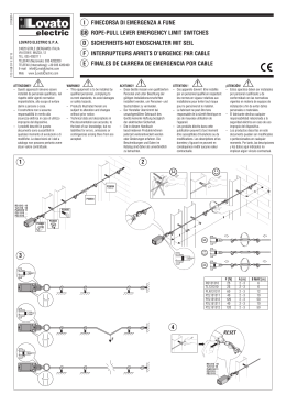
MANUALE ISTRUZIONI D’INSTALLAZIONE, USO E MANUTENZIONE
INSTALLATION USE AND MAINTENANCE INSTRUCTIONS
INSTALLATIONS-, GEBRAUCHS- UND WARTUNGSANLEITUNG
MANUEL D'INSTRUCTION D'INSTALLATION, D'UTILISATION
ET D'ENTRETIEN
FORNI A GAS ED ELETTRICI,
MISTI A CONVEZIONE E VAPORE DIRETTO
PER GASTRONOMIA E PER PASTICCERIA / PANETTERIA
GAS AND ELECTRIC, COMBINED CONVECTION AND
DIRECT STEAM INJECTION OVENS
FOR GASTRONOMY AND FOR PASTRY / BAKERY
GAS- UND ELEKTROÖFEN,
KOMBIBETRIEB MIT KONVEKTION UND DIREKTDAMPF
FÜR DIE GASTRONOMIE UND FÜR KONDITOREI / BÄCKEREI
FOURS À GAZ ET ÉLECTRIQUES,
MIXTES À CONVECTION ET VAPEUR DIRECTE
POUR GASTRONOMIE ET POUR PÂTISSERIE / BOULANGERIE
8711050
1
Il costruttore si riserva il diritto di apportare modifiche alle caratteristiche tecniche e funzionali dei
prodotti presentati in questa pubblicazione senza dare alcun preavviso; inoltre, non risponde di
possibili inesattezze, imputabili ad errori di stampa o di trascrizione, contenute nel presente
libretto.
All specifications of this handbook are not binding and the manufacturer could change them
without notice; the manufacturer declines any liability for possible misprints.
Der Hersteller behält sich vor, die technischen und betrieblichen Merkmale der Erzeugnisse, die in
dieser Veröffentlichung vorgestellt werden, ohne Vorabhinweis zu verändern. Darüber hinaus
haftet er nicht für Unstimmigkeiten, die auf Druck- oder Übertragungsfehler in diesem Heft
zurückzuführen sind.
Le fabricant se réserve le droit d'apporter des modifications aux caractéristiques techniques et
fonctionnelles des produits présentés dans cette publication sans aucun préavis ; en outre, il n'est
pas responsable de possibles erreurs, imputables à des erreurs d'impression ou de transcription,
contenues dans le manuel présent.
INDICE GENERALE- GENERAL INDEX- INHALT- SOMMAIRE
ITALIANO
ENGLISH
DEUTSCH
FRENCH
3
16
28
41
2
ITALIANO- Indice
1. AVVERTENZE
2. CARATTERISTICHE TECNICHE GENERALI
3. AVVERTENZE PER L’INSTALLATORE
4. INDICAZIONI D’UTILIZZO PER L’UTENTE FINALE
5. PANNELLO DI CONTROLLO E LEGENDA
6. VISUALIZZAZIONE DISPLAY
7. DIAGNOSTICA ALLARMI E RIPRISTINO
8. MANUTENZIONE ORDINARIA
9. SMALTIMENTO DELL’IMBALLO
10. DISMISSIONE E ROTTAMAZIONE DELL’APPARECCHIATURA
11. SCHEMI D’INSTALLAZIONE FORNI (ELETTRICO, GAS)
12. SCHEMA ELETTRICO
3
4
5
9
14
14
15
15
15
15
54
58
1. AVVERTENZE
1.1. AVVERTENZE GENERALI
Il presente manuale è stato realizzato per permettere una corretta installazione, messa a punto e manutenzione dell'apparecchiatura.
E’ di fondamentale importanza che le avvertenze contenute nel presente libretto siano lette attentamente in quanto forniscono
importanti indicazioni circa la sicurezza d'installazione, d'uso e di manutenzione.
Il presente manuale e lo schema elettrico devono essere conservati con cura e messi a disposizione dell'operatore (installatore,
tecnico ed anche utilizzatore finale) per ogni ulteriore consultazione.
L'apparecchio deve essere installato, collaudato e assistito da personale qualificato in possesso dei requisiti di legge.
L'apparecchiatura è stata progettata e realizzata per la cottura di prodotti alimentari e per la rigenerazione di alimenti congelati o
surgelati, dovrà pertanto essere destinata solo all'uso per il quale è stata espressamente concepita.
Qualsiasi impiego diverso da quello specificato non comporta per il costruttore impegno o vincolo d'alcun genere.
Viene declinata ogni responsabilità del produttore con decadimento della garanzia in caso di modifiche elettriche e/o meccaniche.
Manomissioni in genere non espressamente autorizzate e che non rispettino quanto riportato nel presente manuale, fanno decadere
la garanzia. Per l'eventuale riparazione rivolgersi esclusivamente ad un centro di assistenza tecnica autorizzato dal costruttore e
richiedere l'utilizzo di ricambi originali.
In caso di dubbio non utilizzare l'apparecchiatura e rivolgersi a personale professionalmente qualificato. Il mancato rispetto di quanto
sopra può compromettere la sicurezza dell'apparecchiatura.
Osservare le norme di sicurezza locali vigenti al momento dell'installazione.
Verificare che le caratteristiche della rete elettrica siano conformi ai dati riportati sulla targhetta matricolare.
Il materiale di imballaggio (sacchetti in plastica, polistirolo espanso, chiodi, ecc.) in quanto potenziale fonte di pericolo deve essere
tenuto fuori dalla portata dei bambini e correttamente riciclato secondo le norme locali in vigore.
1.2. AVVERTENZE TECNICHE GENERALI
- Ogni apparecchiatura è dotata di una targhetta caratteristiche, posta sul lato destro, in basso, che ne identifica il modello e i dati
tecnici principali : LEGGERE I DATI RIPORTATI PRIMA DELL’INSTALLAZIONE.
- L’apparecchiature deve essere installata in un locale aerato e ventilato.
- L’apparecchiatura deve essere adoperata solo da personale adeguatamente formato.
- Tenere lontani i bambini dall’apparecchiatura.
- Se dopo aver posizionato l'apparecchio sul suo supporto la parte più alta supera l'altezza di 1,60 m, è
necessario apporre l’adesivo che trovate insieme alla documentazione fornita insieme all’apparecchiatura:
- L’utilizzo dell’apparecchiatura richiede sorveglianza costante.
Quando il forno è in funzione fare attenzione alle superfici esterne che si riscaldano: evitare di toccarle.
- Chiedere all’installatore l’installazione di un addolcitore d’acqua: in caso di mancanza l’apparecchiatura potrebbe essere
danneggiata gravemente dal calcare.
- Si consiglia l’installazione di un sifone in corrispondenza dell’uscita dell’acqua di scarico del forno.
1.3. AVVERTENZE D’UTILIZZO GENERALI
Al primo utilizzo:
- In fase di primo utilizzo, fare attenzione che il libretto istruzioni, sacchetti di plastica e altri oggetti siano stati tolti dalla camera di
cottura del forno.
- Al primo utilizzo del forno si consiglia di farlo funzionare a vuoto per 30-40 minuti ad una temperatura di 200° C, così da eliminare
odori sgradevoli di materiali usati per isolamenti termici o altri residui di lavorazione.
La pulizia:
- Prima di accendere il forno, per la prima volta, pulire accuratamente la camera di cottura utilizzando prodotti non corrosivi (alcalini)
per non danneggiare le superfici.
- Evitare di utilizzare materiali e prodotti abrasivi per non graffiare le superfici.
- Alla fine dell’utilizzo quotidiano pulire l’interno della camera di cottura e l’esterno dell’apparecchiatura: questo prolungherà la durata
dell’apparecchiatura e ne assicurerà il buon funzionamento.
- Non utilizzare getti d’acqua in pressione per la pulizia del forno.
- Evitare operazioni di salatura all’interno della camera di cottura per non avere incrostazioni o depositi di sale. In caso di depositi
risciacquare immediatamente ed asciugare con cura.
Precauzioni d’uso:
- Per evitare bruciature, non utilizzare contenitori riempiti con liqudi o cibi che possono diventare fluidi con la cottura, nei livelli diversi
da quelli che possono essere facilmente osservati.
- Dopo aver cucinato a vapore aprire con cautela la porta del forno, per evitare d’entrare in contatto improvviso e diretto con il vapore
ad alta temperatura, rimasto in camera di cottura.
- Il non rispetto di questa precauzione potrebbe essere molto dannoso per l’operatore.
- E’ vietato ostruire le prese d’aria e tutte le altre aperture esistenti sul forno, in caso contrario si - comprometterà il funzionamento in
sicurezza dell’apparecchiatura.
Guasto e dismissione:
- Disattivare l'apparecchiatura in caso di guasto o di cattivo funzionamento.
- In caso di dismissione dell’apparecchiatura interrompere e scollegare le linee di alimentazione gas (ove presenti), energia elettrica
ed acqua.
3
TARGHETTA DATI TECNICI FORNI ELETTRICI E A GAS
Matricola - Serial N°
Modello - Model
Type
A1
Voltage
Hz
kW max
Predisp. gas - Gas type
ΣQn (kW)
(kg/h)
(m3/h)
Pin
0051-12
TARGHETTE PREDISPOSIZIONE GAS
Cat
I2E
I3B/P
II2H3+
II2H3+
II2H3+
II2H3+
II2H3B/P
II2H3B/P
II2H3B/P
II2H3B/P
II2H3B/P
II2H3B/P
II2E+3+
II2E3B/P
II2ELL3B/P
II2L3B/P
II2L3B/P
Gas
G20
G25
G30
G31
p (mbar)
p (mbar)
p (mbar)
p (mbar)
p (mbar)
p (mbar)
p (mbar)
p (mbar)
p (mbar)
p (mbar)
p (mbar)
p (mbar)
p (mbar)
p (mbar)
p (mbar)
p (mbar)
p (mbar)
20
20
20
20
20
20
20
20
20
20
20
20
20
20
-
25
20
20
25
30
28-30
28-30
28-30
28-30
30
30
30
30
30
50
28-30
30
50
30
30
30
37
37
37
37
30
30
30
30
30
50
37
30
50
30
30
G20
LU
IS
AL
IT
CZ
ES
AL
DK
LV
RO
TR
AT
BE
RO
DE
RO
NL
G30
20 mbar
PL
MT
CY
LT
MK
CH
BG
EE
LT
SK
SK
FR
HU
GR
PT
SK
TR
CY
FI
NO
SI
IE
GB
SI
HR
GR
MK
SE
CH
G31
28-30 mbar
37 mbar
TARGHETTA AVVERTENZE
IT
QUESTO APPARECCHIO DEVE ESSERE INSTALLATO IN CONFORMITA’
ALLE NORMATIVE VIGENTI E USATO SOLO IN LOCALI BEN VENTILATI
LEGGERE LE ISTRUZIONI PRIMA DELL’INSTALLAZIONE ED USO DELL’ APPARECCHIO
2. CARATTERISTICHE TECNICHE GENERALI
MODELLI
DIMENSIONI ESTERNE
(LxPxH)
(mm)
DIMENSIONI INTERNE
(LxPxH)
(mm)
AFO 640
820x890x690
700x490x440
AFO 644
820x890x750
700x490x440
AFO 641
820x890x970
700x490x720
AFO 645
820x890x1030
700x490x720
AFO 642*
860x970x1810
740x490x1070
AFO 646*
860x970x1865
740x490x1070
AFO 643**
860x970x1810
740x490x1420
AFO 647**
860x970x1865
740x490x1420
CAPACITA’
6
GN1/1, 400x600
6
GN1/1, 400x600
10
GN1/1, 400x600
10
GN1/1, 400x600
15
GN1/1, 400x600
15
GN1/1, 400x600
20
GN1/1
(400x600)
20
GN1/1
(400x600)
* AFO 642, AFO 646 Stand included
** AFO 643, AFO647 Trolley included
4
POTENZA
(Kw)
TOT POTENZA
(Kw)
ELETTR.
9
GAS
13,5
ELETTR.
18
GAS
20
ELETTR.
27
GAS
27
9,4
400V 3N 50Hz
0,6
230V 1N 50Hz
18,6
400V 3N 50Hz
1 ,0
230V 1N 50Hz
27,8
400V 3N 50Hz
1.5
230V 1N 50Hz
37
400V 3N 50Hz
ELETTR.
36
GAS
36
2
230V 1N 50Hz
VOLUME
IMBALLO
(m3)
PESO
LORDO
(kg)
0,74
90
0,74
110
0,98
120
0,98
130
1,8
170
1,5
180
1,8
210
1,8
220
3. AVVERTENZE PER L’INSTALLATORE
Leggere attentamente le istruzioni contenute in questo libretto , perché esse forniscono importanti indicazioni riguardo la sicurezza
dell’installazione, uso e manutenzione del forno. Conservare accuratamente questo manuale di modo da poterlo consultare in caso di
problemi. Le operazioni d’installazione e manutenzione dell’apparecchiatura dovranno essere effettuate da un installatore autorizzato
o da specialisti, conformemente alle norme di sicurezza in vigore. Il costruttore declina ogni responsabilita’ in caso d’inosservanza
delle norme sopra citate. Il costruttore dichiara che le apparecchiature sono conformi alle norme CE. L’installazione dovrà essere
effettuata rispettando le norme in vigore, specialmente quelle riguardanti l’aerazione dei locali ove sarà installata l’apparecchiatura:
installare il forno in un locale ben aerato.
3.1. RICEVIMENTO
L’apparecchiatura arriva protetta da un imballo. Controllare all'arrivo che l'apparecchiatura non abbia subito danneggiamenti durante
il trasporto e che la stessa sia completa nelle sue parti come da ordine. Importante: tutte le operazioni di seguito citate debbono
essere eseguite in conformità' alle norme di sicurezza vigenti, sia per quanto relativo all'attrezzatura usata sia per quanto relativo alle
modalità operative. Attenzione: prima di dar corso ad operazioni di movimentazione assicurarsi che la capacita' di sollevamento sia
adeguata al peso dell'apparecchiatura in questione.
3.2. MOVIMENTAZIONE
Movimentare l’apparecchiatura con carrello elevatore o similare (A): inserire le forche sul lato anteriore o posteriore della pedana di
legno a corredo dell'apparecchiatura. Dar corso al sollevamento assicurandosi che l'apparecchiatura sia in equilibrio stabile.
Attenzione: nel corso della movimentazione non capovolgere o rovesciare. Avvertenze: il rispetto delle raccomandazioni riportate sul
lato esterno dell'imballo è garanzia di integrità fisica e funzionale dell'apparecchiatura a tutto vantaggio dell'utilizzatore finale. Viene
raccomandato quindi di: movimentare con cura, tenere all'asciutto, evitare nel modo più assoluto di sovrapporre altri oggetti
all'apparecchiatura. Sovrapporre solamente con apparecchiature dello stesso modello e tipo e nelle quantita’ (n° pezzi massimi)
riportate sull’imballo (vedere le indicazioni presenti sull’imballo fig. D, E).
3.3. COLLOCAZIONE
- togliere l’imballo (B); togliere manualmente la pellicola di protezione sulle parti in acciaio, evitando di utilizzare sostanze abrasive
e/o oggetti metallici (C); collocare l’apparecchiatura assicurandosi che essa sia perfettamente in piano (C), altrimenti agire sui piedini
ad altezza regolabile affinché essa sia posizionata in maniera corretta. Nel caso di forno+mobiletto neutro, alloggiare i piedini negli
spazi appositamente creati sul mobiletto; collocare l’apparecchiatura ad una distanza almeno di 50 cm dalla parete posteriore e da
una delle 2 pareti laterali per consentire il collegamento del cavo di alimentazione, della rete idrica e del conduttore equipotenziale: la
posizione dell’apparecchiatura deve inoltre permettere un facile accesso, in qualsiasi momento, per tutte le operazioni di
manutenzione ordinaria e straordinaria, nonché per gli interventi di riparazione.
C
B
A
D: INDICAZIONI GENERICHE PRESENTI SULL’IMBALLO
2
1
Numero massimo di pezzi impilabili
E: INDICAZIONI PRESENTI SULL’IMBALLO FORNI A GAS
PREDISPOSTO GAS
CAT
IT
G20
G30
G31
II2H3+
20 mbar
28-30 mbar
37 mbar
- mantenere comunque uno spazio minimo tra il forno e tra il forno e le apparecchiature ad esso vicine (dai 4 ai 6 cm) , questo per
evitare riscaldamento di superfici attigue e per permettere un’adeguata circolazione d’aria.
3.4. COLLEGAMENTI
3.4.1. LAVAGGIO
Fig. 1
B2
C
D
A2
5
Lavaggio (fig. 1)
Parte posteriore del forno (vedere i
differenti modelli in fig. 2)
Connettere:
A 2+ A1
B2+B1
D+D1
C nella tanica detersivo
Fig. 2
B1
A1
SCATOLA LAVAGGIO AUTOMATICO
AUTOMATIC WASHING SYSTEM BOX
C
D= INTERCETTATORE
COCK
D1= ALLACCIAMENTO ACQUA
WATER SYSTEM CONNECTION
TANICA DETERSIVO
DETERGENT TANK
3.4.2. RETE ELETTRICA
Per il collegamento diretto alla rete (vedere SCHEMI INSTALLAZIONE FORNI), è necessario prevedere un dispositivo che assicuri la
disconnessione alla rete, con una distanza di apertura dei contatti che consenta la disconnessione completa nelle condizioni della
categoria di sovratensione III, conformemente alle regole d’installazione.
Verificare che:
la tensione e la frequenza dell’impianto di alimentazione corrispondano a quanto indicato sulla targhetta ‘’dati tecnici’’ apposta
sul lato destro dell’apparecchiatura
l’impianto possa supportare il carico dall’apparecchio (vedere la targhetta con i dati tecnici)
l’impianto sia munito di messa a terra secondo le norme in vigore
il sezionatore del forno sia raggiungibile facilmente anche dopo aver posizionato ed installato l’apparecchiatura
esempio di tipologia cavo di alimentazione:
Tipologia cavo
FG7R/FG70R
FG7R/FG70R
FG7R/FG70R
FG7R/FG70R
FG7R/FG70R
FG7R/FG70R
FG7R/FG70R
FG7R/FG70R
Sezione Ø (mm²)
5x10
5x6
5x6
5x4
5x4
5x2,5
5x2,5
3x2,5
kW elettrico
36
27
24
18
12
6
9
3,2
la tensione di alimentazione, quando il forno è in funzione, non si discosti dal valore nominale di ± 10%
I forni a gas sono dotati di cavo con spina Schuko (monofase 230 V): inserire la spina nella presa elettrica dopo aver verificato che la
presa sia adatta alla spina in dotazione. I forni trifase, non sono dotati di cavo elettrico, quindi è necessario collegare alla morsettiera
interna del forno un cavo di adeguata sezione (vedi schema elettrico).
Sostituzione del cavo: la sostituzione del cavo deve essere eseguita da personale autorizzato e competente; dopo aver aperto la
copertura inferiore, posta nella parte posteriore del forno (svitando la vite di fissaggio), collegare i conduttori secondo lo schema di
collegamento scelto. Fissare il cavo con l’apposito pressa cavo e poi chiudere il coperchio posteriore.
Se il cavo di alimentazione è danneggiato, esso deve essere sostituito dal costruttore o il suo servizio assistenza tecnica o comunque
da una persona con qualifica similare, in modo da prevenire ogni rischio.
6
3.4.2.1. SIMBOLO EQUIPOTENZIALITA’
COLLEGAMENTO EQUIPOTENZIALE: necessario al collegamento di tutte le apparecchiature
(elettriche e neutre) presenti nell’installazione al fine di garantire un collegamento equipotenziale.
3.4.3. RETE IDRICA
Tra la rete idrica e l’apparecchiatura è preferibile mettere un rubinetto di intercettazione.
L’apparecchiatura è munita di un attacco maschio 3/4’’ e di filtro meccanico; utilizzare esclusivamente il set di collegamento alla rete
idrica fornito insieme all’apparecchiatura, avvitando il bocchettone femmina del tubo in dotazione, sul filtro meccanico da ¾’’ (vedere
SCHEMI INSTALLAZIONE FORNI ELETTRICI E GAS).
Prima di installare il tubo di alimentazione si consiglia di fargli scorrere all’interno acqua corrente in modo da pulire eventuali residui o
polvere. Dati dell’acqua:
- La pressione consigliata per l’acqua in ingresso deve essere inferiore a 200 kPa.
- Per pressioni maggiori è necessario installare un riduttore di pressione tarato a 200 kPa.
- La temperatura massima dell’acqua circa 30° C
- La durezza massima 5°F (onde evitare incrostazioni calcaree, dannose per l’apparecchiatura).
- Si consiglia l’uso di un addolcitore per l’acqua per evitare qualsiasi deposito di minerali nel forno.
DA FARSI IN FASE DI INSTALLAZIONE ALLA RETE IDRICA: è obbligatorio appena fatta l’ installazione alla rete idrica
avviare un set up lavaggio, come descritto al paragrafo LAVAGGIO.
3.4.4. GAS
La sezione del tubo di adduzione gas deve essere scelta a seconda del tipo di gas e dal consumo dell’apparecchiatura da allacciare.
L’impianto deve essere progettato ed eseguito in opera secondo le norme vigenti. L’apparecchiatura a gas è dotata di un attacco da
½’’ gas maschio posizionato nella parte posteriore del forno (vedere SCHEMI INSTALLAZIONE FORNI GAS).
L’allacciamento a tale attacco va effettuato con appositi adattatori e guarnizioni idonei al tipo di combustibile utilizzato (vedi dati
tecnici). Deve essere posto a monte del forno un rubinetto di intercettazione rapida per la chiusura del gas (omologato dalle vigenti
normative). Si possono avere due tipi di collegamenti: fisso o scollegabile. Nel caso di impiego di tubi flessibili dovranno essere
resistenti alla corrosione e in materiale inossidabile. Eventuali materiali di tenuta utilizzati nel collegamento dovranno essere
omologati secondo le vigenti norme di legge. Per le prove di tenuta di tutti i raccordi tra impianto ed apparecchiatura si consiglia l’uso
di spray cercafughe; si possono anche spennellare, nei punti di raccordo, sostanze schiumose non corrosive. Ovviamente in entrambi
i casi NON DEVONO COMPARIRE BOLLE. QUANDO SI EFFETTUANO TALI PROVE, EVITARE FIAMME LIBERE.
3.4.5. SCARICHI
Acqua
Il tubo previsto, per l’acqua di scarico, deve essere di un materiale in grado di sopportare la temperatura dell’acqua in uscita dal forno
(90° C) deve essere posizionato dietro il forno (vedere SCHEMI INSTALLAZIONE FORNI ELETTRICI E GAS) e collegato ad uno
scarico sifonato per mezzo di un condotto rigido o flessibile. Il tubo avrà diametro 32 cm e lunghezza pari ad un metro senza gomiti o
strozzature e per facilitare il deflusso fare in modo che sia 20 cm al di sotto dell’attacco scarico.
Fumi
Lo scarico dei fumi è sull’apparecchiatura in alto verso lo schienale: attenzione a non otturare i camini di scarico ed accertarsi che i
camini non sfiatino in corrispondenza di materiali o arredi che ne potrebbero risultare danneggiati. Dopo aver verificato quanto sopra
il forno può essere posizionato sotto una cappa aspirante (dotata di filtro) o sotto un soffitto aspirante.
FORNI A GAS: IL FORNO DEVE ESSERE POSIZIONATO SOTTO UNA CAPPA DI ASPIRAZIONE O SISTEMA ANALOGO.
IL SISTEMA DI ASPIRAZIONE DEVE ESSERE ASSERVITO ALL’IMPIANTO GAS.
3.5. FORNI A GAS: SOSTITUZIONE DEGLI UGELLI.
TABELLA SOSTITUZIONE UGELLI.
POTENZA TERMICA NOMINALE
kW 13,5
UGELLI
G30 28..30 mbar
G30 50 mbar
G20 20 mbar
G25 25 mbar
G25 20 mbar
kW 20
G30
G30
G20
G25
G25
28..30 mbar
50 mbar
20 mbar
25 mbar
20 mbar
G31 30…37 mbar
G31 50 mbar
G31 30…37 mbar
G31 50 mbar
marking
90
80
140
150
155
110
95
175
185
195
Si raccomanda prima di accingersi a compiere la sostituzione degli ugelli di chiudere il rubinetto del gas.
7
A- Svitare le 4 viti che fissano il pannello copertura bruciatore
B- Levare il pannello copertura inferiore bruciatore
BRUCIATORI
COPERTURA
BRUCIATORI
1
2
3
4
Vista del bruciatore
C- Svitare le viti 1 e 2 che sorreggono il bruciatore di sinistra e le viti 3 e 4 che sorreggono il bruciatore di destra
3
1
2
4
BRUCIATORE SINISTRO
BRUCIATORE DESTRO
D- Sfilare il bruciatore di sinistra e successivamente quello di destra
8
E- Dopo aver sfilato i bruciatori, svitare i due ugelli del bruciatore di sinistra e i 2 ugelli del bruciatore di destra
F- Togliere ugelli+guarnizioni
G- Mettere nuovi ugelli+gurnizioni
H- Infilare nuovamente i bruciatori e fissarli con le loro viti.
I- Rimettere la copertura inferiore ai bruciatori e fissarla con le sue 4 viti.
L- Aprire nuovamente la conduttura del gas.
4. INDICAZIONI D’UTILIZZO PER L’UTENTE FINALE
4.1. ALIMENTAZIONE DELLA SCHEDA
La scheda appena alimentata si porta nello stato STAND-BY, se, quando è stata spenta, non era in corso alcun ciclo di cottura. Si
porta nello stato “STOP TEMPORANEO” , se era in corso un ciclo di cottura.
4.2. STATO “MANCANZA TENSIONE”
In questo stato la scheda non è alimentata e non sono accesi LED, tasti o display.
4.3. STATO “STAND-BY”
In questo stato la scheda è alimentata. Tutti i display e i LED sono spenti. L’unico tasto illuminato è il tasto (1) ON-OFF.
Premendo il tasto ON-OFF, dopo 3 secondi (pressione lunga) la scheda si porta nello stato PRONTO.
4.3.1. GESTIONE PARAMETRI.
Per entrare in Menu’ Parametri dallo stato Stand by schiacciare contemporaneamente il tasto MENU’ (11) e (14) LAVAGGIO per 3
sec. Appare la scritta del menu’ ‘’SERVICE PARAM’’, schiacciare ENTER (12) , compare la scritta ‘’PASSWORD’’, schiacciare (12)
ENTER. La prima voce del menù service è “PARAM” che permette la gestione dei parametri. I parametri sono protetti da password;
quando si tenta di entrare nel menu parametri viene chiesto di inserire la password, impostabile con l’encoder e confermabile con il
tasto ENTER: per l’utente vale ‘’0’’ (zero).
IND
42
46
48
49
76
79
DESCRIZIONE
Timeout luce
Lingua
Tempo aspirazione con tasto UTempo iniezione con tasto U+
Timeout autospegnimento
Offset di temperatura in preriscaldamento
MIN
0
0
10
10
0
0
MAX
30 min
5
60 sec
60 sec
30
25
DEF
60
0
10
10
20
0
UM
SEC
--SEC
SEC
MIN
°C
All’interno del menù parametri viene mostrato l’indice di parametro e il suo valore. Si scorrono i vari parametri utilizzando l’encoder.
Premendo il tasto (12) ENTER si seleziona il parametro e i led FASI lampeggiano, indice che è possibile modificarlo. Il cambio di
valore viene effettuato utilizzando l’encoder. Premendo il tasto (12) ENTER si conferma il valore, premendo il tasto (10) ESC si esce
dalla modifica del parametro senza confermare la modifica.
Premendo il tasto (10) ESC dalla lista di scorrimento dei parametri si torna al menù service.
4.4. STATO “PRONTO”
In questo stato la scheda è pronta per l’impostazione e l’avvio di un ciclo di cottura. Il LED ON-OFF si spegne. Al passaggio a questo
stato il display temperatura indica per 5 sec il set impostato (è acceso anche il puntino a destra dell’ultima cifra), poi passa alla
visualizzazione della temperatura misurata della camera (si spegne il puntino). La visualizzazione del set impostato (camera o deltaT)
è identificata dall’accensione del puntino a destra dell’ultima cifra. I display tempo e programma e i LED umidità e fasi riportano le
impostazioni dell’ultimo ciclo di cottura manuale salvato. Il numero di led fasi accesi indica il numero di fasi del programma
selezionato e il led fase lampeggiante indica quale fase del ciclo è attualmente visualizzata. Se presenti allarmi essi vengono
visualizzati nel display programma e il buzzer suona. Alla prima pressione di un tasto il buzzer viene tacitato. Se è possibile il
ripristino manuale dell’allarme, esso viene effettuato premendo il tasto (10) CANC prolungatamente. In assenza di allarmi e a ciclo
impostato e confermato la pressione singola del tasto (2) START/STOP fa partire il ciclo di cottura e porta la scheda in stato di
START. La pressione prolungata del tasto (1) ON/OFF porta la scheda in stato di STAND-BY.
4.4.1. IMPOSTAZIONE CICLO DI COTTURA
In generale l’impostazione di un ciclo di cottura è una sequenza di azioni vincolante e auto-correttiva dall’alto in basso. Questo
significa che il modo cottura (a tempo o a spillone) e il tipo di set della temperatura (setpoint camera o delta t) saranno sempre
coerenti e non in contraddizione, ovvero per esempio non è possibile impostare una cottura a tempo con delta t.
Di seguito le modalità di cottura ammesse:
9
- A tempo e setpoint camera
- A spillone e setpoint camera
- A spillone e delta t
La precedenza di impostazione è data al modo cottura. Questo significa che se per esempio è impostata la modalità a tempo e
setpoint camera, al tentativo di impostazione della modalità a delta t avviene un segnale sonoro di errore. E’ quindi necessario prima
impostare il modo cottura a spillone e poi impostare la modalità a delta t.
L’impostazione è auto-correttiva nel senso che non permette impostazioni incongruenti. Ad esempio se è impostata la modalità a
spillone e delta t e si imposta il modo cottura a tempo viene impostata automaticamente anche la modalità a setpoint camera.
4.4.1.1. COTTURA A TEMPO
La cottura a tempo necessita dell’impostazione prima del tempo di cottura e poi della temperatura della camera.
Per l’impostazione del tempo di cottura premere il tasto (4) TEMPO. Il led relativo lampeggia. L’indicazione temporale è nel formato
hh.mm. Tramite (13) l’encoder è possibile selezionare un tempo tra 0h.01min e 9h.59min, a passi di 1min. E’ prevista anche la
possibilità di impostare un tempo di cottura infinito, visualizzato a display come INF (nel caso in cui si seleziona INF la variabile tempo
ha durata illimitata) ed una modalita di preriscaldamento , visualizzata a display come PRE (vedi 4.4.1.7). La modalità di selezione è
a rotazione, ovvero dopo 9h.59min compare INF, PRE e poi 0h.01min. Il valore viene impostato con il tasto (12) ENTER. Dopo un
tempo impostabile da parametro (default 10sec) senza pressione di tasti o rotazioni di encoder oppure premendo il tasto (10) CANC o
(4) TEMPO ritorna il valore precedente non lampeggiante.
Per l’impostazione della temperatura della camera premere il tasto (6) TEMP. CAMERA. Il led relativo lampeggia. L’indicazione della
temperatura è nell’unità °C (o °F su richiesta). Tramite l’encoder è possibile selezionare una temperatura tra un valore minimo e uno
massimo impostabili da parametro. Il valore viene impostato con il tasto (12) ENTER. Dopo un timeout impostabile senza pressione
di tasti o rotazioni di encoder oppure premendo il tasto (10) CANC o (6) TEMP. CAMERA ritorna il valore precedente non
lampeggiante.
4.4.1.2. COTTURA A SPILLONE
La cottura a spillone prevede due diverse modalità: a setpoint camera e a delta T.
La cottura a setpoint camera necessita di impostare prima la temperatura dello spillone e poi la temperatura della
camera.L’impostazione del set di temperatura dello spillone è comune a entrambe le modalità e viene effettuata premendo il tasto (5)
SPILLONE. Il led relativo lampeggia. Il display a fianco indica il set della temperatura dello spillone nell’unità °C (o °F su richiesta).
Tramite l’encoder è possibile selezionare una temperatura e impostare il valore con il tasto (12) ENTER.L’impostazione della
temperatura della camera avviene con la stessa modalità che nella cottura a tempo. Tuttavia la temperatura del set camera deve
essere superiore al set dello spillone di un valore minimo di 30° C. La cottura a delta-t necessita di impostare prima il set della
temperatura dello spillone e poi la differenza di temperatura tra camera e spillone.
La differenza di temperatura tra camera e spillone viene settata premendo il tasto (7) DELTA T. Il led relativo lampeggia. Il display a
fianco indica il set della differenza. Tramite (13) l’encoder è possibile selezionare una temperatura e impostare il valore con il tasto
(12) ENTER.
4.4.1.3. IMPOSTAZIONE UMIDITA’
Il setpoint dell’umidità viene visualizzato per mezzo dei 10 LED umidità rossi e blu. Essi rappresentano una scala di umidità tabulata
in 11x2 valori che va dalla cottura a vapore (5 LED blu accesi) alla cottura secca (5 LED rossi accesi). L’impostazione dell’umidità
della camera avviene premendo il tasto (8) UMIDITA’. Questo lampeggia ed è possibile selezionare l’umidità tramite (13) l’encoder e
memorizzarla con il tasto (12) ENTER.
4.4.1.4. IMPOSTAZIONE VELOCITA’ VENTOLE
Con il tasto (3) SET VELOCITA’ è possibile la selezione della velocità delle ventole, se abilitata da parametro inserito dal costruttore.
Premendo il tasto si passa ciclicamente da alta velocità a bassa velocità; con bassa velocità selezionata è acceso il relativo LED, con
alta velocità selezionata il LED è spento. E’ possibile impostare velocità diverse nelle varie fasi di cottura.
4.4.1.5. FASI DI COTTURA
Ciascun ciclo di cottura, sia esso una ricetta o un ciclo manuale, può essere composto fino a un massimo di 4 fasi. Il numero di led
fasi accesi indica il numero di fasi del programma selezionato e il led fase lampeggiante indica quale fase del ciclo è attualmente
visualizzata.
La fase selezionata può essere cambiata a rotazione premendo il tasto (9) FASI.
Tenendo premuto il tasto (10) CANC viene cancellata la fase selezionata. Le fasi seguenti traslano a sinistra di una posizione
(facendo riferimento alla notazione con i led gialli delle fasi). Non è possibile cancellare tutte le fasi di un programma, in quanto esso
deve essere composto almeno da una fase.
Tenendo premuto il tasto (9) FASI viene creata una nuova fase identica alla fase selezionata e viene aggiunta di seguito alla fase
selezionata. Le fasi seguenti quella selezionata traslano a destra di una posizione (facendo riferimento alla notazione con i led gialli
delle fasi). Non è possibile creare una fase dopo la quarta. Se sono già presenti 4 fasi e ne viene creata una nuova la quarta viene
eliminata.
4.4.1.6. COTTURA A TEMPO RITARDATO
Per impostare un ciclo a tempo ritardato, ruotare l’encoder temperatura sotto il valore minimo di 30°. Sul display B comparirà la
scritta ‘’PAU’’ , ciò significa che durante questa fase di cottura il forno rimarrà in pausa per un tempo definito dal display A. Alla fine
di tale fase nel caso sia presente una fase successiva, il forno passerà a quest’ultima.
4.4.1.7. PRERISCALDAMENTO
Per riscaldare il forno prima di cucinare, si devono impostare 2 fasi di cottura: il riscaldamento e la cottura vera e propria
(naturalmente si possono aggiungere ulteriori fasi).
Sequenza di operazioni:
1. impostare la fase 1 con tempo PRE e temperatura di riscaldamento prescelta
2. creare la fase 2
3. modificare la fase 2 con temperatura e tempo adatti al tipo di cottura (la fase 2 può essere anche di tipo o a spillone o a Δt)
Dopo queste operazioni il forno è pronto per il funzionamento.
Premendo il tasto (2) START/STOP, il forno parte senza carico di cibo in cottura e si porta alla temperatura impostata nella fase 1:
quando viene raggiunta tale soglia, la tastiera emette 2 bip segnalando il raggiungimento della temperatura di preriscaldamento.
Da questo momento in poi si possono introdurre le pietanze da cuocere. Quando viene richiusa la porta del forno, si avrà
automaticamente il passaggio alla fase successiva (vengono emessi 2 bip). Se la porta viene aperta e chiusa prima che il forno abbia
raggiunto la temperatura finale di preriscaldamento (cioè prima che vengano emessi i 2 bip), si avrà comunque il passaggio alla fase
successiva.
4.4.1.8. RAFFREDDAMENTO
Con il forno in stato di STOP (quindi a ciclo non avviato) è possibile eseguire un raffreddamento veloce a porta aperta. Aprendo infatti
la porta, sul display a bandiera compare la scritta COOL e contemporaneamente lampeggiano i tasti ENTER (12) e CANC (10). Se si
10
preme ENTER si conferma l’opzione di raffreddamento, viceversa con CANC si ritorna al normale funzionamento del forno. Se la
temperatura della cella è inferiore a 60°c il raffreddamento non può iniziare.
Una volta confermata l’opzione COOL la pressione singola del tasto (2) START/STOP avvia il raffreddamento. Il raffreddamento ha
fine quando vengono raggiunti i 60°c o quando si richiude la porta. In ogni caso il raffreddamento può essere interrotto con la
pressione singola del tasto (2) START/STOP.
4.4.2. PROGRAMMI DI COTTURA
Il forno può memorizzare fino a un massimo di 200 programmi (compresi i quelli pre-memorizzati in uscita dalla fabbrica), con nomi di
max 10 lettere. I programmi sono organizzati in 2 livelli: il primo livello consiste in 9 categorie di programma:
MANUALE-POLLAME-CARNE-PESCE-VERDURA-PASTICCERIA-PANE-PIZZA-VARIE.
Il secondo livello specifica il particolare programma (ad esempio POLLO, ANATRA, ARROSTO,...). Ogni categoria (ad eccezione di
MANUALE) può essere formata da un numero a piacere di programmi, con il vincolo del numero massimo di programmi totali (200
programmi).
Il forno è dotato di un set di programmi pre-memorizzati in uscita dalla fabbrica e non modificabili. Questi sono resi disponibili tradotti
in 4 lingue ma non è prevista alcuna traduzione automatica del nome dei programmi memorizzati in seguito. Non è permesso
spostare o clonare i programmi da una categoria a un’altra. Premendo il tasto (11) MENU / MEMO (pressione singola) si entra nella
modalità programmi. Il led MENU/MEMO lampeggiante indica che si è in modalità selezione programma ed è possibile scorrere i
programmi della categoria corrente. Sul display a bandiera (D) viene visualizzato a scorrimento il programma (2° livello). Con (13)
l’encoder si scorrono i programmi e con (12) ENTER si seleziona il programma. Con il tasto (10) CANC (pressione singola) si passa
al livello superiore (categoria di programma). Caso particolare è la modalità MANUALE, per la quale non è prevista una lista di
programmi di 2° livello. Per cui, quando è selezionata la modalità manuale, premendo il tasto (11) MENU/MEMO si passa
direttamente alla selezione di categoria di programma. Il led MENU/MEMO acceso fisso indica che si è in modalità selezione
categoria di programma. Sul display a bandiera viene visualizzato a scorrimento il nome della categoria di programma corrente (1°
livello). Con (13) l’encoder si scorrono le categorie e con (12) ENTER si seleziona la categoria. Con il tasto CANC (pressione singola)
si esce dalla modalità programmi. Apportando modifiche al programma selezionato queste vengono tenute buone per il ciclo di
cottura successivo ma non vengono memorizzate. Tenendo premuto il tasto (12) ENTER vengono memorizzate le modifiche
apportate al programma, a meno che esso non faccia parte dei programmi costruttore che sono non modificabili.
Con il tasto (9) FASI si possono scorrere le varie fasi del programma e modificarne le impostazioni secondo quanto descritto nel
paragrafo 4.4.1.5. Tenendo premuto il tasto (10) CANC per 5 secondi (dalla modalità selezione programma) viene eliminato il
programma visualizzato. Non è possibile eliminare i programmi pre-impostati dalla fabbrica. Con il tasto (2) START/STOP si avvia il
programma selezionato. Tenendo premuto il tasto (11) MENU / MEMO per 5 secondi (con il programma selezionato e non dalla lista
programmi) è possibile clonare il programma selezionato, a parte quando è selezionato il programma manuale, nel qual caso
vengono direttamente salvate le modifiche. Ciascun programma è identificato da una stringa (nome) e da un indice, che viene
rappresentato mediate i puntini del display a bandiera. Così il programma POLLO[2] viene rappresentato scrivendo sul display a
bandiera POLLO e accendendo i 2 puntini a sinistra del display a bandiera. Clonando un programma, appare sul display a bandiera il
nome del programma selezionato e il primo indice disponibile. E’ possibile avere un massimo di 6 cloni dello stesso programma; se
esistono già 6 cloni viene proposto l’indice numero 6, con l’opportunità di sovrascriverlo. Per programmi con nomi superiori a 6 lettere
vengono visualizzate le ultime 6 lettere del nome. Ad esempio modificando ARROSTO viene visualizzato RROSTO. L’ultimo digit è
lampeggiante, a indicare che può essere modificato ruotando l’encoder. Premendo il tasto (12) ENTER la scritta scorre di un digit a
sinistra aggiungendo una nuova cifra “_” (underscore) lampeggiante e modificabile in coda al nome. Premendo il tasto (10) CANC
viene eliminato l’ultimo digit del nome, facendo scorrere la parola verso destra e potendo modificare la sua nuova ultima lettera.
Volendo cambiare completamente il nome è necessario premere ripetutamente il tasto (10) CANC fino a che non rimane un solo digit
lampeggiante. A quel punto è possibile riscrivere l’intero nome. Non è possibile scegliere l’indice di un programma, esso viene
assegnato automaticamente. Se viene modificato il nome l’indice viene azzerato (nessun puntino acceso). Tenendo premuto il tasto
(11) MENU / MEMO viene memorizzato il nuovo programma e si passa al menù di selezione programma. In caso di sovrascrittura ne
viene chiesta la conferma con la stringa SOVRASC. Il tasto (12) ENTER conferma la sovrascrittura e porta al menù di selezione
programma, il tasto (10) CANC fa ritornare al menù di modifica. Non è possibile sovrascrivere un programma costruttore. In tal caso
viene proposto il nome del programma costruttore e il primo indice disponibile. Tenendo premuto il tasto (10) CANC dal menu di
modifica si esce dal salvataggio del programma. Raggiunta la quota di 200 programmi appare la scritta “MEM PIENA” al tentativo di
clonare un nuovo programma; è possibile tuttavia la sovrascrittura di uno precedente o è necessario liberare spazio cancellando un
programma utente.
4.5. STATO “START”
In stato di START/STOP la scheda avvia il ciclo di cottura selezionato e inizia le regolazioni. Tenendo premuto il tasto (2)
START/STOP la scheda si porta in stato PRONTO. Premendo il tasto (2) START/STOP (pressione singola) o aprendo la porta la
scheda si porta in stato di STOP TEMPORANEO. E’ possibile apportare modifiche ai set della fase di cottura in corso; esse non
vengono però memorizzate e vengono tenute buone solo per il ciclo in corso. A fine ciclo esse vengono eliminate.Non è possibile
cambiare modalità di cottura (tempo o spillone) né selezionare un programma diverso. Tenendo premuto il tasto (9) FASI viene
terminata la fase in corso e si passa alla successiva. Il buzzer emette un bip prolungato. Se era in corso l’ultima fase il ciclo viene
terminato. La fase in esecuzione è segnalata dal led FASI lampeggiante. Alla fine del ciclo la scheda si porta in stato PRONTO e il
buzzer emette una serie di bip.
4.6. STATO “STOP TEMPORANEO”
In stato di STOP TEMPORANEO vengono sospese le regolazioni e spenta la ventola. Premendo nuovamente il tasto (2)
START/STOP riprende il ciclo di cottura se la porta è chiusa. Chiudendo la porta riprende il ciclo di cottura se l’interruzione è
avvenuta in seguito ad un’apertura della porta (e non è stato premuto il tasto START/STOP). Premendo il tasto (2) START/STOP
prolungato la scheda si porta in stato PRONTO. E’ possibile apportare modifiche ai set della fase di cottura in corso; esse non
vengono però memorizzate e vengono tenute buone solo per il ciclo in corso. A fine ciclo esse vengono eliminate. Non è possibile
cambiare modalità di cottura (tempo o spillone) né selezionare un programma diverso. Tenendo premuto il tasto (9) FASI viene
terminata la fase in corso e si passa alla successiva. Il buzzer emette un bip prolungato. Se era in corso l’ultima fase il ciclo viene
terminato. La fase in esecuzione è segnalata dal led FASI lampeggiante.
4.7. GESTIONE USB DELLE RICETTE (OPTIONAL)
Il forno prevede la possibilità di utilizzare una chiavetta USB (Mass storage device) per la gestione delle ricette; in particolar modo
prevede di poter importare ed esportare programmi di cottura. Essa viene effettuata dal menu USB, che si trova in coda alla lista delle
categorie di programma: premere MENU (11), ruotando l’ENCODER (13) si leggeranno:
MANUALE --> POLLAME --> CARNE --> PESCE --> VERDURA --> PASTICCER -->PANE-->PIZZA-->VARIE--> USB
Tale menù è presente solo quando è connessa una chiavetta USB; in caso contrario la lista si ferma all’ultima categoria.
Selezionando con il tasto ENTER (12) il menu USB si trova una lista di 2 opzioni: IMPORTA, ESPORTA
Se si è dentro al menu USB e viene sconnessa la chiavetta, si ritorna all’ultima categoria di programma.
IMPORTAZIONE DI RICETTE
Selezionando la voce IMPORTA, premendo ENTER (12) si avvia il processo di importazione delle ricette presenti nel file formattato
REC_IN.csv.
11
La formattazione del file è la seguente:
>>
RICETTA a
>>
RICETTA b
...
>>
RICETTA n
>>EOF
Ciascuna ricetta ha il seguente formato
Tipologia ricetta : categoria[1];nome[10];numero[1];sovrascrittura[1]
Fase1: modo cottura[1];umidità[2];set camera[3];set tempo[3];set spillone[3];set delta t[3];set ventole[2]
Fase2: modo cottura[1];umidità[2];set camera[3];set tempo[3];set spillone[3];set delta t[3];set ventole[2]
Fase3: modo cottura[1];umidità[2];set camera[3];set tempo[3];set spillone[3];set delta t[3];set ventole[2]
Fase4: modo cottura[1];umidità[2];set camera[3];set tempo[3];set spillone[3];set delta t[3];set ventole[2]
Il numero tra parentesi quadre a fianco di ciascun campo indica il numero di caratteri da cui è composto il campo. Il significato di
ciascun campo è il seguente:
categoria: è la categoria a cui appartiene la ricetta. I valori accettati sono:
0 manuale; 1 pollame; 2 carne; 3 pesce;4 verdura; 5 pasticceria; 6pane; 7pizza. 8varie
nome: è il nome della ricetta visualizzato sul display a bandiera. E’ possibile un massimo di 10 caratteri. I caratteri accettati sono tutte
le lettere maiuscole, i numeri, underscore, trattino e spazio.
numero: è il numero che identifica programmi con lo stesso nome (cloni). Viene rappresentato dai puntini sul display a bandiera. Può
variare da 0 (0 puntini) a 6 (6 puntini).
sovrascrittura: definisce il comportamento nel caso in cui si tenti di importare una ricetta con un nome già memorizzato nel forno.
Esso può assumere solo 2 valori:
0: non sovrascrivere. Viene creato un nuovo clone, identificato dal primo numero successivo libero. Se ad esempio sono esistenti
POLLO, POLLO[1], POLLO[3] e si cerca di importare POLLO, viene creato il nuovo programma POLLO[2]
1: sovrascrivi. Se è possibile viene sovrascritto il programma presente sul forno, a meno che non sia uno dei programmi costruttore,
che non sono modificabili.
modo cottura: definisce il modo cottura della relativa fase. I valori accettati sono:
0 : fase assente (la fase marchiata con 0 e le successive non vengono memorizzate)
1 : cottura a tempo
2 : cottura a spillone
3 : cottura a delta t
umidità: definisce il set dell’umidità della relativa fase. Può assumere i valori da 0 a 10, in cui 0 è cottura secca, 10 cottura a vapore.
set camera, set spillone, set delta t: definiscono i setpoint relativamente della camera, dello spillone e della cottura a delta t della
relativa fase. I valori accettati vanno da 0 a 275.
set tempo: definisce il tempo di cottura della fase relativa, in una cottura a tempo, espresso in minuti. Esso può variare da 0 (cottura
infinita) a 599 (9h:59min).
set ventole: definisce la velocità di rotazione delle ventole nella relativa fase. Può assumere i valori 0 (mezza velocità) e 1 (piena
velocità)
Qualora si usino meno di 4 fasi, non è necessario impostare i valori delle fasi restanti con 0 (FASE ASSENTE).
Di seguito un esempio di file REC_IN.csv (in grassetto) e a fianco il commento a ciascuna riga.
>> 001
Nuova ricetta (il numero progressivo è ininfluente)
0;
;0;0
Programma manuale (nome,numero e sovrascrivi ininfluenti)
1;05;150;010;050;020;01
Fase1 a tempo 10 min 150 gradi, umidità 5, ventole piena vel
1;05;250;010;050;020;01
Fase2 a tempo 10 min 250 gradi, umidità 5, ventole piena vel
>> 002
Nuova ricetta (il numero progressivo è ininfluente)
1;FARAONA ;0;1
Categoria pollame, nome FARAONA, no clone, sovrascrivere
1;05;220;015;050;020;01
Fase1 a tempo 15min 220gradi, umidità 5, ventole piena vel
1;05;190;045;050;020;00
Fase2 a tempo 45min 190gradi, umidità 5, ventole mezza vel
1;05;225;010;050;020;01
Fase3 a tempo 15min 225gradi, umidità 5, ventole piena vel
>> 003
Nuova ricetta (il numero progressivo è ininfluente)
1;FARAONA ;1;0
Categoria pollame, nome FARAONA, clone n1, no sovrascrivere
1;05;220;015;050;020;01
Fase1 a tempo 15min 220gradi, umidità 5, ventole piena vel
1;05;190;045;050;020;01
Fase3 a tempo 15min 225gradi, umidità 5, ventole piena vel
>>EOF
Fine del file
Il processo di importazione può richiedere anche parecchi secondi (nel caso di importazione di molte ricette); durante tale periodo
viene visualizzata la scritta WAIT sul display a bandiera. Nel caso in cui si abbia raggiunto il numero massimo di 100 ricette
(costruttore + utente) previste per il forno, la creazione di nuove ricette non è possibile e la scansione del file REC_IN.csv prende in
considerazione solo le sovrascritture di ricette.
ESPORTAZIONE DI RICETTE
Selezionando la voce ESPORTA, premendo ENTER (12) si avvia il processo di esportazione delle ricette presenti nel forno. Le ricette
sono salvate in un file csv formattato di nome REC_OUT.csv. Il formato del file di esportazione è identico a quello per l’importazione,
in modo che possa venire agevolmente utilizzato per creare un file di importazione. Le ricette vengono esportate per ordine di
categoria e in ogni categoria vengono ordinate alfabeticamente (in maniera identica alla lista visualizzata scorrendo i programmi sul
display a bandiera). All’inizio di ogni ricetta viene riportato un numero progressivo (>>000, >>001, >>nnn), utile per ritrovare il numero
totale di ricette presenti nel forno. Tale numero può essere lasciato nel file di importazione delle ricette, nel quale non assume alcun
significato e viene ignorato. Durante il processo di esportazione viene visualizzata la scritta WAIT sul display a bandiera.
4.8. LAVAGGIO
ATTENZIONE DA FARSI ALLA PRIMA INSTALLAZIONE!!!
SET UP LAVAGGIO : Premendo il tasto (14) LAVAGGIO una volta e successivamente una seconda volta prolungata (10 sec.)
nel display D compare la scritta ‘’SET UP’’; a questo punto schiacciare il tasto (2) START/STOP in questo modo si avvia per
circa 2 minuti il carico del detergente.
Attenzione: il SET UP si avvierà solamente a temperatura camera forno inferiore a 60°.
Con il forno in stato PRONTO (led ON/OFF spento) premere LAVAGGIO (14); selezionare con L’ENCODER (13) NORMALE, FORTE
o EXTRAFORTE e RISCIACQUO e con ENTER (12) confermare l’opzione scelta. Per cominciare il ciclo di lavaggio premere (2)
START. ATTENZIONE: il ciclo di lavaggio partirà solamente quando la temperatura della camera forno sarà uguale a 60°.
Per terminarlo definitivamente premere a lungo il tasto (2) START/STOP. Se il forno non è in START (2) per resettare e tornare
indietro premere prima LAVAGGIO (14) e poi CANC (10).
12
ATTENZIONE: SE IL SET UP LAVAGGIO O UN CICLO DI LAVAGGIO, NON GIUNGONO A BUON FINE BISOGNA
ASSOLUTAMENTE AVVIARE UN CICLO DI RISCIACQUO O LAVARE IL FORNO MANUALMENTE; QUESTO PER EVITARE CHE
RESIDUI DI DETERGENTE POSSANO RIMANERE IN CAMERA DI COTTURA DURANTE LE COTTURE SUCCESSIVE
ENTRANDO IN CONTATTO CON I CIBI.
4.9. GESTIONE HACCP (OPTIONAL)
Il log HACCP delle cotture può essere effettuato solo nei modelli in cui è presente l’hardware per la gestione dell’orologio.
Il forno permette di registrare le temperature ed eventi significativi durante il ciclo di cottura. In particolare vengono memorizzati i
seguenti dati:
Data (giorno, mese e anno)
Orario (ora e minuti)
Temperatura della sonda camera in gradi
Temperatura della sonda spillone in gradi
Stato del relè camera (PWM 0: diseccitato / PWM 100: eccitato)
Eventi significativi (start, stop, pausa, apertura porta, ripresa cottura da power-up)
Allarmi
Gli eventi salvati sono:
START: partenza o ripresa di una cottura dopo una pausa
STOP: termine di una cottura
PAUSE: pausa in una cottura
DOOR: apertura della porta durante una cottura
POWER-UP: ripresa di una cottura dopo un power fail
I codici di errore salvati sono (essi sono visibili solo scaricando il log dal menù service):
1 Sicurezza camera
2 Sicurezza ventola
3 Sicurezza bruciatore
6 Mancanza comunicazione
7 Alta temperatura scheda potenza
Gli eventuali errori della sonda camera e spillone sono rappresentati da ERR al posto del valore della temperatura (essi sono visibili
anche nel log scaricato dall’utente).
Il salvataggio dei dati avviene durante l’esecuzione di un ciclo di cottura (stato START o STOP TEMPORANEO) e a termine cottura
fino a che non viene aperta la porta e comunque per un tempo massimo di 15 min.
Il campionamento avviene con periodo di 5 min. oppure ogni volta che la temperatura dello spillone subisce una variazione superiore
a 5 gradi. La memoria di salvataggio può contenere circa 2000 campionamenti (campionando ogni 5 minuti si possono raccogliere
circa 160 ore di dati); al riempimento della memoria vengono eliminate le registrazioni relative al giorno più vecchio in memoria.
La memoria viene svuotata ogni volta che viene effettuato lo scaricamento dei dati su chiavetta USB.
Lo scaricamento dei dati in memoria avviene connettendo una chiavetta USB alla tastiera e selezionando la voce HACCP nel menù
USB in coda alla lista delle categorie di programma. I dati vengono scaricati su un file nominato Hggmmaa.csv in cui gg/mm/aa sono
giorno, mese e anno del ciclo più vecchio in memoria; nel caso sia già presente un file con lo stesso nome, quest’ultimo viene
sovrascritto. Il file è composto da un’intestazione contenente delle informazioni di carattere generale e da un corpo contenente le
informazioni salvate in memoria. Di seguito un esempio di formattazione del file di log HACCP comprensivo degli errori (i dati sono
stati tabulati per una maggior comprensione):
LOG HACCP
Software version: V203R022 ; Download date: 00/00/00 - 00:00
Date;
Time;
T Chamber;
T Core;
PWM;
Event;
18/04/2011;
16:18;
23;
0;
0;
START;
18/04/2011;
16:18;
24;
0;
100;
;
18/04/2011;
16:19;
78;
0;
100;
;
18/04/2011;
16:19;
94;
0;
100;
;
18/04/2011;
16:19;
107;
0;
100;
;
18/04/2011;
16:19;
124;
0;
100;
;
18/04/2011;
16:19;
146;
0;
100;
;
18/04/2011;
16:20;
149;
0;
100;
;
18/04/2011;
16:20;
148;
0;
100;
DOOR;
18/04/2011;
16:20;
147;
0;
0;
;
18/04/2011;
16:20;
138;
0;
0;
;
18/04/2011;
16:20;
137;
0;
0;
START;
18/04/2011;
16:20;
142;
0;
100;
;
18/04/2011;
16:20;
154;
0;
0;
;
18/04/2011;
16:20;
149;
0;
100;
;
18/04/2011;
16:20;
153;
0;
0;
;
18/04/2011;
16:20;
155;
0;
0;
STOP;
18/04/2011;
16:20;
157;
0;
0;
;
18/04/2011;
16:21;
147;
0;
0;
;
Il mantenimento dei dati in memoria e dell’ora in mancanza di alimentazione esterna è stimato in circa 150 ore.
4.9.1. IMPOSTAZIONE OROLOGIO “TIME” (SOLO SE PRESENTE HACCP)
Questo menù è presente solo qualora venga identificata la presenza dell’hardware per la gestione dell’orologio. E’ un menù utente a
cui si accede senza password premendo il tasto ENTER. Vengono visualizzate sul display a bandiera la data e l’ora attuali e si passa
poi al menù di modifica dell’orologio. Se non viene effettuata alcuna operazione di modifica, premendo il tasto ESC si esce dal menù
lasciando inalterata data e ora. Con l’encoder si modifica e conferma il valore visualizzato, con ENTER si passa alla modifica del
valore successivo con scorrimento ciclico della lista. La lista dei valori visualizzata è la seguente:
DAY xx impostazione del giorno (01-31)
MON xx impostazione del mese (01-12)
YEA xx impostazione dell’anno (11-50)
HOU xx impostazione dell’ora (00-23)
MIN xx impostazione dei minuti (00-59)
Premendo il tasto ESC si conferma il dato e si scrive la nuova data; i secondi vengono posti a 0.
4.10. SPEGNIMENTO
Per terminare la cottura in corso in qualsiasi momento premere (2) STOP/PAUSA. Per spegnere definitivamente il forno premere (1) ON/OFF.
13
5. PANNELLO DI CONTROLLO E LEGENDA
1
2
BASSA VELOCITÀ VENTOLA
4
TEMPO DI COTTURA
5
SONDA AL CUORE
7
4
START - STOP - STOP TEMPORANEO
3
6
5
6
7
TEMPERATURA CAMERA DI COTTURA
PARTENZA RITARDATA
COTTURA
8
t°
8
UMIDITÀ
9
FASE DI COTTURA
10
CANCELLA-INDIETRO
11
MENÙ-SALVA RICETTA
12
CONFERMA
13
SELEZIONE
14
LAVAGGIO (OPTIONAL)
15
AUMENTO MANUALE DELL’UMIDITÀ
16
RIDUZIONE MANUALE DELL’UMIDITÀ
11
9
10
12
13
15
16
6. VISUALIZZAZIONE DISPLAY
DISPLAY
PARAM
OROLOGIO
SERV_1
SERV_2
VERS
TERMIC
VENTOL
BRUC
SONDCE
SONDSP
COMSER
TPSCH
GENER
MANUALE
POLLAME
CARNE
PESCE
VERDURA
PASTICCER
PANE
PIZZA
VARIE
LAVAGGIO
MEM PIENA
SOVRASCR
USB
IMPORTA
ESPORTA
HACCP
ANATRA
POLLO
TACCHINO
MAIALE
MANZO
VITELLO
BRANZINO
ROMBO
TROTA
SCAMPI
CAROTE
PATATE
PISELLI
RADICCHIO
BRIOCHES
PANETTONE
BAGUETTE
MARGHERITA
LIEVITA
NORMALE
FORTE
EXTRAFORTE
RISCIACQUO
SETUP
2
3
1
ON/OFF
DESCRIZIONE
Stringa menù service per entrare nei parametri
Stringa menù per impostazione orologio
Stringa menù service per collaudo scheda
Stringa menù service per cancellare i programmi utente
Stringa menù service per visualizzare versione firmware
Errore termico sicurezza
Errore ventola
Errore bruciatore
Errore sonda camera
Errore sonda spillone
Errore comunicazione seriale
Errore temperatura scheda potenza
Errore generale
Categoria di programma
Memoria piena quando si tenta un salvataggio di programma
Richiesta di sovrascrittura per un programma
Menù USB
Importazione ricette da USB
Esportazione ricette da USB
Esportazione file log HACCP
Nome ricetta costruttore pre-memorizzata
Programma di lavaggio
14
14
7. DIAGNOSTICA ALLARMI, RIPRISTINO.
Tutti gli allarmi vengono visualizzati sul display programmi.
7.1. AVARIA SONDA CAMERA
Se la sonda camera è in avaria con la scheda negli stati PRONTO, START e STOP TEMPORANEO viene visualizzato il messaggio
di allarme “ERR SONDCE” e si attiva il buzzer. Un’eventuale cottura viene interrotta e la scheda passa nello stato PRONTO. Alla
pressione di un qualsiasi tasto viene tacitato il buzzer. Il ripristino avviene quando la sonda camera non è più in avaria (autoripristino).
7.2. AVARIA SONDA SPILLONE
Se la sonda spillone è in avaria, con la scheda negli stati START e STOP TEMPORANEO e la fase corrente o una di quelle
successive contiene una cottura a spillone o deltaT la cottura viene interrotta e la scheda passa nello stato STOP TEMPORANEO.
Sul display a bandiera appare la scritta “ERR SONDSP” e si attiva il buzzer. La scheda non va in allarme se in stato PRONTO,
MANCANZA TENSIONE e STAND-BY. Alla pressione di un qualsiasi tasto viene tacitato il buzzer. Il ripristino avviene in maniera
automatica quando la sonda spillone non è più in avaria (autoripristino).
7.3. ALLARME MANCANZA COMUNICAZIONE
Se manca comunicazione tra scheda potenza e scheda tastiera per più di 10 secondi, la scheda tastiera entra in allarme, viene
visualizzato il messaggio di allarme “ERR COMSER” e si attiva il buzzer.
La scheda non va in allarme se in stato MANCANZA TENSIONE e STAND-BY. Un’eventuale cottura viene interrotta e la scheda
passa nello stato PRONTO. Alla pressione di un qualsiasi tasto viene tacitato il buzzer. Il ripristino avviene in maniera automatica
quando riprende la comunicazione (autoripristino).
7.4. ALLARME TEMPERATURA SCHEDA POTENZA
Se la temperatura misurata dalla scheda potenza supera il valore limite (impostato dal costruttore) la scheda tastiera entra in allarme,
viene visualizzato il messaggio di allarme “ERR TPSCH” e si attiva il buzzer. La scheda non va in allarme se in stato MANCANZA
TENSIONE e STAND-BY. Un’eventuale cottura viene interrotta e la scheda passa nello stato PRONTO. Alla pressione di un qualsiasi
tasto viene tacitato il buzzer. Il ripristino avviene in maniera automatica quando la temperatura scende al di sotto il limite di sicurezza.
7.5. PORTA APERTA
In START nel caso di porta aperta si passa nello stato STOP TEMPORANEO e lampeggia il led del tasto START/STOP. Vengono
disabilitati tutti i relè eccetto il relè luce. La cottura viene sospesa fino a che la porta non viene chiusa.
7.6. INGRESSI SICUREZZA
La scheda è dotata di tre ingressi sicurezza: sicurezza camera, sicurezza bruciatore, sicurezza ventole.
Nel caso occorra uno dei precedenti allarmi viene visualizzato il relativo messaggio di allarme e si attiva il buzzer con la scheda negli
stati PRONTO, START e STOP TEMPORANEO.
I messaggi di allarme sono i seguenti:
- “ERR BRUC” relativo alla sicurezza bruciatore
- “ERR TERMIC” relativo al termostato di sicurezza camera
- ‘’ERR VENTOL’’ relativo al protettore motore ventola
La scheda non va in allarme se in stato MANCANZA TENSIONE o STAND-BY. Un’eventuale cottura viene interrotta e la scheda
passa nello stato PRONTO. Il tentativo di ripristino avviene, come indicato dal forno stesso, tenendo premuto il tasto CANC.
7.7. MANCANZA DI TENSIONE
Quando si ha un’interruzione sull’alimentazione e la scheda è in stato START o STOP TEMPORANEO, al successivo power on la
scheda si porta in STOP TEMPORANEO potendo riprendere l’eventuale ciclo di cottura precedente. Il programma temporaneo è
memorizzato ogni 10 minuti e su cambiamento di fase.
Se la scheda non era in START o STOP TEMPORANEO la scheda si porta in stato STANDBY e viene caricato il programma
manuale memorizzato. Non si hanno allarmi associati alla mancanza di tensione.
8. MANUTENZIONE ORDINARIA
Tutte le operazioni di manutenzione devono essere effettuate unicamente da personale qualificato.
Prima di iniziare qualsiasi operazione di manutenzione è obbligatorio spegnere l’apparecchiatura e scollegarla dalla rete elettrica (se
l’apparecchiatura è a gas chiudere il rubinetto del gas) e dalla rete idrica.
PULIZIA DEL FORNO
Pulire il forno alla fine del servizio giornaliero con prodotti adeguati:
1- usare acqua tiepida e saponi neutri o detergenti neutri
2- risciacquare accuratamente con acqua
3- asciugare con cura
Non usare spatole o spazzole abrasive o altri utensili: questi potrebbero rovinare le superfici in acciaio e rilasciare depositi ferrosi che
con l’andare del tempo creerebbero ruggine.
Non utilizzare getti d’acqua per lavare il forno.
Per pulire le parti in acciaio non utilizzare prodotti a base di cloro (candeggina, acido cloridrico) nemmeno se sono diluiti in acqua.
Dopo ogni cottura specifica e prima della successiva, è consigliabile pulire eventuali resti di alimenti (grassi o sughi) nella camera di
cottura del forno. Per la pulizia della camera di cottura del forno si raccomandano prodotti adatti e accuratezza
nell’operazione:tralasciare piccoli depositi di cibo o grasso negli angoli reconditi potrebbe a lungo andare danneggiare
l’apparecchiatura e creare fumi e odori indesiderati nella camera di cottura, nei casi più gravi ostruire prese d’aria o danneggiare
movimenti meccanici.
In caso di inutilizzo dell’apparecchiatura per lungo periodo si raccomanda di:
1- spegnere l’apparecchiatura con il suo tasto (OFF)
2- chiudere i rubinetti che la collegano alla rete elettrica, idrica e gas (ove presente)
3- lasciare leggermente aperta la porta dell’apparecchiatura affinché ci sia un passaggio d’aria e l’apparecchiatura non abbia
fenomeni di condensa o odori all’interno della camera di cottura
4- con l’aiuto di un panno stendere un velo protettivo d’olio di vaselina su tutte le superfici in acciaio inox.
SI RACCOMANDA DI SOTTOPORRE L’APPARECCHIATURA PERIODICAMENTE (ALMENO UNA VOLTA L’ANNO) AD UN
CONTROLLO TOTALE DA PARTE DI UN TECNICO SPECIALIZZATO.
9. SMALTIMENTO DELL’IMBALLO
Smaltire i prodotti di imballo facendoli confluire ai centri di raccolta o di riciclaggio specializzati attenendosi alle norme vigenti.
10. DISMISSIONE E ROTTAMAZIONE DELL’APPARECCHIATURA
Nel caso di dismissione, prima di rottamare l'apparecchiatura è doveroso renderla inoperante togliendo il cavo d'alimentazione,
eliminando quelle parti che possono costituire un pericolo e rendendo inservibili maniglia, cerniera od altri sistemi.
IMPORTANTE: RISPETTARE LE NORMATIVE LOCALI PER LA ROTTAMAZIONE DI QUESTO GENERE DI APPARECCHIATURA.
15
ENGLISH- Index
1. WARNINGS
2. GENERAL TECHNICAL FEATURES
3. WARNINGS FOR THE INSTALLER
4. INDICATIONS FOR THE FINAL USER
5. CONTROL PANEL AND LEGEND
6. VISUALIZATION ON DISPLAY
7. DIAGNOSE OF ALARMS (ERRORS) AND THEIR RESTORE
8. ORDINARY MAINTENANCE
9. PACKING AND DISPOSE OF IT
10.DISPOSAL OF UNIT
11. INSTALLATION SCHEME
12. WIRING DIAGRAM
16
17
18
22
26
27
27
27
27
27
54
58
1. WARNINGS
1.1. GENERAL WARNINGS
This manual has been prepared to enable a correct installation, regulation and maintenance of the appliance. It is therefore of basic
importance that the warnings contained in this booklet are carefully read as they supply essential indications regarding the safety of
the installation, use and maintenance. This manual and the wiring diagram must be stored with care and made available to the
operator (technical qualified personnel, final user) for any future consultation. The appliance must be installed, tested and
serviced by legally qualified personnel. The appliance has been designed and constructed for the cooking of foodstuffs and
should therefore be destined to this sole purpose for which it has been expressly conceived. Any use besides this specific purpose
does not commit the constructor in any way. The constructor declines all responsibility with invalidity of the warranty in the event of
electrical and/or mechanical modifications. Any adjustment whatsoever not expressly authorised and in disrespect of this
manual will cause the invalidation of the warranty. For eventual repairs contact exclusively the authorised service centre and request
the use of original spare parts. If in doubt do not use the appliance and contact professionally qualified personnel. The disrespect of
the above conditions could risk the safety of the appliance. Observe all existing local regulations at the time of installation. Check
that the characteristics of the electric grid correspond to the data given on the serial plate of the appliance. The packing materials
(plastic bags, polystyrene, nylon, etc.) as potential hazards, must be kept out of the reach of children and properly recycled
according to the existing local regulations.
1.2. TECHNICAL GENERAL WARNINGS
every appliance has a technical data plate on the right side, reporting the model and the main characteristics: read carefully the
technical data before installing the appliance!!!
- Place the oven in a ventilated room.
- The appliance is intended for professional use and must be used only by qualified personnel only.
- Keep off the children from the appliance above all if it is in function.
- If the heigh of the composition oven+stand exceed 1,60 mt, it is necessary to put the safety sticker that you find among the
documents of the oven
- The appliance should be constantly overseen while operating.
- There are surfaces of the oven that become hot during operation. Take care of this.
- Ask the installer for information on correct operation and use of the water softener; incorrect or incomplete maintenance is at the
origin of the formation of scale, which would badly damage the oven.
- It’s suggested to install a siphon placed at the exit of drain water.
- Every appliance has a serial data plate on the right side.
1.3. GENERAL USE WARNINGS
Starting to use the oven: at the first use .
- Pay attention to remove from the cooking chamber all stranger material like manual, plastic bags, polystyrene, nylon, etc, before
starting to operate with the oven
- Leave the cooking chamber empty and heat up the oven about 30-40 minutes long at the temperature of 200°C to eliminate any
thermic insulation smell.
Cleaning
- Clean the inside and outside surfaces only with warm water and soap or a neutral detergent. Rinse with plenty of water and dry
thoroughly.
- Don’t use abrasive brushes or other damaging materials for the appliance’s surfaces.
- At the end of the working day, clean the inside (above all) and outside of the oven , to ensure smooth operation of the appliance and
to prolong its useful life.
-Do not use high pressure water jets when cleaning the appliance.
- Avoid any operation that might cause cooking salt to be deposited on the steel surfaces of the oven; if salt is accidentally spilled,
rinse off immediately and thoroughly.
Using precautions
- Open the door of the oven slowly, to avoid to get burned by the hot steam.
- Never obstruct any air inlet on the oven, in order to not compromise its performance and safety, when the appliance is operating
- Never stretch the power cable.
- To avoid burns, never use containers completely filled with foodstuffs which could became liquid, in levels which can’t be easily saw.
Breakdown and final disposing
- Shutdown the appliance in the event of breakdown or malfunctions.
- Dsconnect it from electrical, gas (if you have a gas oven) and water system.
- For the final disposal of this appliance, comply with local regulations in force.
16
GENERAL TECHNICAL DATA PLATE ELECTRIC AND GAS OVENS
Matricola - Serial N°
Modello - Model
Type
A1
Voltage
Hz
kW max
Predisp. gas - Gas type
ΣQn (kW)
(kg/h)
(m3/h)
Pin
0051-12
GAS CARACTERISTICS
Cat
I2E
I3B/P
II2H3+
II2H3+
II2H3+
II2H3+
II2H3B/P
II2H3B/P
II2H3B/P
II2H3B/P
II2H3B/P
II2H3B/P
II2E+3+
II2E3B/P
II2ELL3B/P
II2L3B/P
II2L3B/P
Gas
G20
G25
G30
G31
p (mbar)
p (mbar)
p (mbar)
p (mbar)
p (mbar)
p (mbar)
p (mbar)
p (mbar)
p (mbar)
p (mbar)
p (mbar)
p (mbar)
p (mbar)
p (mbar)
p (mbar)
p (mbar)
p (mbar)
20
20
20
20
20
20
20
20
20
20
20
20
20
20
-
25
20
20
25
30
28-30
28-30
28-30
28-30
30
30
30
30
30
50
28-30
30
50
30
30
30
37
37
37
37
30
30
30
30
30
50
37
30
50
30
30
G20
20 mbar
G30
LU
IS
AL
IT
CZ
ES
AL
DK
LV
RO
TR
AT
BE
RO
DE
RO
NL
PL
MT
CY
LT
MK
CH
BG
EE
LT
SK
SK
FR
HU
GR
PT
SK
TR
CY
FI
NO
SI
IE
GB
SI
HR
GR
MK
SE
CH
G31
28-30 mbar
37 mbar
WARNINGS
IT
THIS APPLIANCE MUST BE CONNECTED FOLLOWING THE NORMATIVE LAWS IN FORCE.
THIS ITEM MUST BE USED IN A VENTILATED PLACE ONLY. BEFORE THE INSTALLATION AND
THE USE OF THE APPLIANCE. INSTRUCTIONS MUST BE READ DOWN CAREFULLY.
2. GENERAL TECHNICAL FEATURES
MODELS
EXTERNAL DIM.
(LxPxH)
(mm)
INTERNAL DIM.
(LxPxH)
(mm)
AFO 640
820x890x690
700x490x440
AFO 644
820x890x750
700x490x440
AFO 641
820x890x970
700x490x720
AFO 645
820x890x1030
700x490x720
AFO 642*
860x970x1810
740x490x1070
AFO 646*
860x970x1865
740x490x1070
AFO 643**
860x970x1810
740x490x1420
AFO 647**
860x970x1865
740x490x1420
CAPACITY
6
GN1/1, 400x600
6
GN1/1, 400x600
10
GN1/1, 400x600
10
GN1/1, 400x600
15
GN1/1, 400x600
15
GN1/1, 400x600
20
GN1/1
(400x600)
20
GN1/1
(400x600)
* AFO 642, AFO 646 Stand included
** AFO 643, AFO647 Trolley included
17
POWER
(Kw)
TOT POWER
(Kw)
ELETTR.
9
GAS
13,5
ELETTR.
18
GAS
20
ELETTR.
27
GAS
27
9,4
400V 3N 50Hz
0,6
230V 1N 50Hz
18,6
400V 3N 50Hz
1 ,0
230V 1N 50Hz
27,8
400V 3N 50Hz
1.5
230V 1N 50Hz
37
400V 3N 50Hz
ELETTR.
36
GAS
36
2
230V 1N 50Hz
VOLUME
PACKED
(m3)
GROSS
WEIGHT
(kg)
0,74
90
0,74
110
0,98
120
0,98
130
1,8
170
1,5
180
1,8
210
1,8
220
3. WARNINGS FOR THE INSTALLER
Read carefully all the instructions in this manual, because they give important suggestions about the right installation, use and
maintenance of the appliance.
3.1. CONTROLS AT RECEPTION
The appliance are shipped in appropriate protective packing. On arrival, check that the appliance has not incurred in transport
damage and that it is complete according to the order. In the event of visible damage immediately note the damage on the transport
documents with the following wording: “RECEIVED WITH RESERVE FOR EVIDENT DAMAGE OF PACKING”.
ALL THE OPERATIONS INDICATED BELOW MUST BE PERFORMED IN RESPECT OF THE EXISTING SAFETY REGULATIONS,
BOTH FOR THE EQUIPMENT IN USE AND FOR THE OPERATING PROCEDURES.
3.2. HANDLING
BEFORE BEGINNING HANDLING OPERATIONS ENSURE THAT THE LIFTING CAPACITY IS ENOUGH FOR THE APPLIANCE IN
QUESTION. HANDLING with FORK LIFT or SIMILAR (A); Insert the forks into the side or back of the wooden pallet supplied with the
appliance, begin lifting checking that the appliance is in stable equilibrium. Attention: when insert the lifting device, pay attention to the
power supply cable and the position of the feet. DURING HANDLING DO NOT TIP OR TURN OVER.
the respect of the recommendations printed on the outside of the packing (D, E) is a guarantee of a sound physical and operating
condition of the appliance, all to the advantage of the end-user. therefore the following is recommended: handle with care, keep dry,
stacking of other objects on the appliance must be absolutely avoided, stacking of oven is permitted, taking care of the maximal
quantity reported on the packaging (D)
3.3. PLACING
Lift the appliance to separate it from the pallet (A). Remove the packing (B) and the protective film avoid using abrasive brushes or
other damaging materials for the appliance’s surfaces (C). Check that the appliance is perfectly levelled (C).
Regulate the adjustable feet if it is necessary. If you have a composition oven + neutral element, place the oven’s legs in the proper
place created in the top of the neutral element.Place the appliance away from heat sources and in a ventilated room. Never obstruct
any air inlet on the oven in order to not compromise its performance and safety when the equipment is operating .Place the
appliance in a site easy to join, so every type of maintenance, control and repair may be done easily.
C
B
A
D:GENERAL INDICATIONS ON THE PROTECTIVE PACKING
2
1
Maximal quantity of stackable units
E: INDICATIONS ON THE PROTECTIVE PACKING OF THE GAS OVEN
GB
THIS APPLIANCE MUST BE CONNECTED FOLLOWING THE NORMATIVE LAWS
IN FORCE. THIS ITEM MUST BE USED IN A VENTILATED PLACE ONLY.
BEFORE THE INSTALLATION AND THE USE OF THE APPLIANCE.
INSTRUCTIONS MUST BE READ DOWN CAREFULLY. THIS PACKAGING HAS TO BE
PROPERLY RECYCLED ACCORDING TO THE EXISTING LOCAL REGULATIONS.
CAT
II2H3+
GAS PREDISPOSED
G20
G30
G31
20 mbar
28-30 mbar
37 mbar
- It is strictly recommended to have a free space of 50 cm from the back side of the oven to the wall and from one of the two sides to
the wall in order to ensure a correct and easy connection to the equipotential system and to the electriocal and water system.
- it is recommended to have 4-6 cm of distance from the other appliances to guarantee a proper air circulation and avoid the near
surfaces to became overheated.
3.4. CONNECTIONS
3.4.1. AUTOMATIC WASHING SYSTEM
Fig. 1
B2
C
A2
D
18
Washing box (fig. 1)
Back side of the oven (see different
models in fig. 2)
Connections:
A2 + A1
B2+B1
D+D1
C in detergent tank
Fig. 2
B1
A1
SCATOLA LAVAGGIO AUTOMATICO
AUTOMATIC WASHING SYSTEM BOX
C
D= INTERCETTATORE
COCK
D1= ALLACCIAMENTO ACQUA
WATER SYSTEM CONNECTION
TANICA DETERSIVO
DETERGENT TANK
3.4.2. ELECTRICAL CONNECTION
For the direct connection to the electric system it’s necessary a device to ensure the disconnection fron the electric system, with a
contacts opening able to disconnect completely the electric system in the conditions of category of over voltage III, in accordance
with installation regulations.
The connection must be done according to the current local regulations. Verify that:
Voltage and frequency correspond to those stated on the data plate of the appliance.
The electrical plant supports the consumption of electricity of the appliance.
The electrical plant has a grounding to the current local regulations.
The appliance must be placed in such a way that the interlocked switched socket-outlets to the network can be easily reached.
Example of type of electric cable:
Cable type
FG7R/FG70R
FG7R/FG70R
FG7R/FG70R
FG7R/FG70R
FG7R/FG70R
FG7R/FG70R
FG7R/FG70R
FG7R/FG70R
Ø (mm²)
5x10
5x6
5x6
5x4
5x4
5x2,5
5x2,5
3x2,5
kW electric
36
27
24
18
12
6
9
3,2
When the appliance is operating, the power supply voltage must not diverge from the value of the nominal voltage, indicated on
the data plate, by more than ± 10 %.
Gas ovens are equipped with cable and Schuko plug (single phase 230 V).
Insert the plug in the socket only if you are sure that the socket is right for the plug. Three phases ovens are not supplied with
electrical cable, therefore it is necessary to connect to the oven internal terminal board a cable of proportionate section.
Cable replacement: after opening the lower cover, placed in back side of the oven (unscrew the fixing screw), connect the
conductives in accordance with the selected wiring diagram. Fix the cable to the suitable cable gland and close the back cover.
The connection or replacement of the cable has to be done by authorized personnel.
If the cable is damaged it has to be sustituted by authorized personnel.
3.4.2.1. EQUIPOTENTIAL SYMBOL
EQUIPOTENTIAL CONNECTION: it’s necessary when different appliances have to be connected (electrical or neutral) in an equipotential
system.
19
3.4.3. WATER CONNECTION
Between the water system and the appliance you have to put a tap.
The appliance is equipped with a 3/4’’ male thread and of a mechanic filter. The appliance is equipped with a connection water set:
you have to use only this for oven’s water connection! You have to screw the female thread of the tube to the mechanic filter of ¾’’.
Before installing the alimentation tube is recommended to let flow running water to clean impurities and dust.
Characteristics of water:
- it is recommended a pressure less than 200 kPa for the enter of water.
- for greater pressures, install a pressure regulator calibrated at 200 kPa.
- water max temperature= 30° C
- maximum hardness: 5°F (to avoid calcium deposits, which are harmful for the equipment).
- it is recommended the installation of a water softener to avoid the formation of mineral depots.
OPERATION TO PERFORM DURING THE INSTALLATION PHASE TO THE WATER NETWORK: After performing the
installation to the water network, it is compulsory to run a washing set up, as described in paragraph WASHING SYSTEM.
3.4.4. GAS CONNECTION
The section of the enter gas tube depends on the gas type and on the consumption of the installed oven. The connection must be
done according to the current local regulations. The gas oven is equipped with a ½’’ male thread positioned in the back side of the
oven (see the drawing below).
The connection has to be done with fitting adapters and gaskets appropriate for the used gas type (see technical data).
A fast acting shutoff valve must be installed on the gas inlet line to the oven. The valve must be type test approved according to the
current regulations. The connections of the gas main can be permanent or detachable; if flexible metal tube is used, this should be
made of stainless and corrosion resistant material (do not use rubber hose!). Every type of chosen sealing material used for
connections have to be tested and approved for this purpose. All connections between the mains and the appliance must be tested
for leakage. The recommended method is to use a proprietary leak detection spray or a non-corrosive foamy liquid of any general
description can simply be brushed onto the fittings: the important thing is that NO BUBBLES SHOULD APPEAR. WARNING: NEVER
ANY CIRCUMSTANCES TEST FOR GAS LEAKS WITH A NAKED FLAME.
3.4.5. DRAINING WATER AND STEAM EMISSION
Water
The water is drained through a pipe made of a heat resistance material. The temperature of the draining water is about 90°C. It must
be positioned in the back side of the oven and connect to a siphoned drain through a rigid or flexible pipe. The diameter of the pipe
will be 32 mm and length 1,00 mt without elbows or narrow passagings and in order to an easy drainage it is recommended
installing 20 cm under the draining connection.
Vents
Vents are positioned on the top of the oven: don’t block, shut or duct into other pipes. Kept a distance between the vents and
materials or furniture which could be damaged. Gas oven may be positioned under a suction hood or under a ducted ceiling suitable
for gas.
3.5. GAS OVENS: SOSTITUTION OF NOZZLES.
TABLE FOR NOZZLE SUBSTITUTION
THERMIC NOMINAL POWER
NOZZLES
kW 13,5
G30 28..30 mbar
G30 50 mbar
G20 20 mbar
G25 25 mbar
G25 20 mbar
kW 20
G30
G30
G20
G25
G25
28..30 mbar
50 mbar
20 mbar
25 mbar
20 mbar
G31 30…37 mbar
G31 50 mbar
G31 30…37 mbar
G31 50 mbar
marking
90
80
140
150
155
110
95
175
185
195
You have to close the gas tap before make any operation.
A- Unscrew the 4 screws which fix the back cover panel of the burners.
B- Remove the lower back cover panel of the burners
BURNERS
COVER OF THE
BURNERS
1
2
3
4
20
Burners
C- Unscrew the screws 1, 2 of the left burner and 3,4 of the right burner.
3
1
7
2
4
LEFT BURNER
RIGHT BURNER
D- Remove the left burner and after the right one.
E- After removing the burners, unscrews the 2 nozzles of the left burner and the 2 nozzles of the right burner.
F- eliminate the nozzles + washer
G- mount the new nozzles in the place of the old ones .
H- mount again the burners and fix them with their own screws.
I- mount the burner lower panel and fix it with its own screws.
L- open the gas tap.
21
4. INDICATIONS FOR THE FINAL USER
4.1. POWER SUPPLY
When the card is powered up goes to STAND-BY status, if there wasn’t a cooking cycle carrying out, in the moment of the switching
off. If a cooking cycle was carrying out it goes to TEMPORARY STOP.
4.2. POWER OFF
The card is powered off: led, keys or the displays are off.
4.3. STAND-BY
In this status the card is powered up. All the displays and led aren’t lightened. Only the (1) ON-OFF key is lightened.
By pressing the ON-OFF key the card goes to READY mode.
4.3.1. PARAMETERS MANAGEMENT
The first voice of menu service is ‘’PARAM’’ and is useful for the parameters management. The PARAMETERS are protected with a
password; when you try to enter in parameters menu you have to digit the password, with the rotation of the encoder (13) and confirm
by pressing the key ENTER (12): for the final use is ‘’0’’ (zero).
IND
DEF
DESCRIPTION
MIN
MAX
UM
42
60
Timeout light
0
30 min
s
46
0
Languages
0
5
--48
10
Aspiration time with the key U10
60 sec
s
49
10
Injection time with the key U+
10
30
s
79
Pre-heating temperature offset
0
0
25
°C
Within parameters menu is showed the parameter index and its value. You may run the various parameters with the encoder.
By pressing the key (12) ENTER you select the parameter and the led PHASES begins to blink: it means that you can modify it.
You can change the value with the ENCODER (12). BY pressing ENTER you confirm the value, by pressing the key ERASE (10) you
go out from the changing of the parameter without confirm the modify. By pressing the key ERASE (10) you go back menu service.
4.4. READY
In this mode the card is ready to set up and start a cooking cycle. ON-OFF led switches off.
If you pass in this mode the temperature’s display shows for 5 sec the choose set (is lightened the dot at the right of the last digit) and
after it shows the measured chamber’s temperature (the dot is not lightened) . The visualization of the choose set (chamber or deltaT) is identified by the lightening of the dot at the right side of the last digit. The displays of programs and temperatures and the led of
humidity and phases, carry the set up of the last manual cooking cycle’s memorized. The lightened phases’ led number show the
number of the phases of the selected program and the blinking phase’s led shows which phase is at present visualized.
If there are alarms they are shown in program’s display and the buzzer sounds. At the first pressure of a key the buzzer stop to
sound. If it’s possible the alarm’s manual restore, it has done by a long pressure of the key (10) . If there are no alarms and with a set
up and confirmed the short pressure of the START/STOP (2) key starts a cooking cycle and the card goes to START mode. The card
goes to STAND-BY mode with a long pressure of the (1) ON/OFF key.
4.4.1. SET UP A COOKING CYCLE
Set up a cooking cycle is a binding and auto-corrective actions’ sequence from top to lower part. It means that the cooking mode
(Time or Core Probe) and the type of temperature’s setting (chamber or delta t) will be not in contradiction and will be always
consistent: for example isn’t possible setting up a cooking time mode with a delta-t.
Cooking modes accepted:
- Time and chamber’s set point
- Core probe and chamber’s set point
- Core probe and delta T
The cooking mode has the setting up priority. It means that if it’s set up the TIME mode and CHAMBER’S SET POINT is not possible
setting up DELTA T mode, infact it starts the alarm’s sound. It’s necessary to set up first of all the CORE PROBE mode and after
DELTA T mode. The setting up is auto-corrective, it not allows incongruous set up. For example if core probe mode and delta t mode
are set up and after it’s set up TIME mode also will be automatically set up CHAMBER SETPOINT mode.
4.4.1.1. TIME COOKING MODE
TIME COOKING mode needs the setting up of the cooking time and after of the chamber temperature.
To set up cooking time press the (4) TIME key (its led begins to blink). Time is showed in hh.mm. With (13) ENCODER it’s possible to
select a time between 0h.01min and 9h.59min, with 1 min. step length. It is also possible to set an infinite cooking time, displayed
as INF (if INF is selected, the time variable has an unlimited duration), and a pre-heating mode, displayed as PRE (see 4.4.1.7). The
mode for selection is rotation, that is, after 9h. 59min, INF, PRE is shown, and then 0h.01min. The value is set up by pressing the
key (12) ENTER. If you don’t press keys or rotate the encoder, after a fixed time (default 10sec) the value goes back to its previous
setting and it not blinks. The same happens by pressing the key (10) CANC or (4) TIME. To set up the chamber’s temperature press
the key (6) CHAMBER TEMP. . Its led begins to blink. Temperature is showed in the unity of measure selected by a parameter. With
ENCODER is possible to select a temperature between a min and a max values set up by a parameter. Value is confirmed by
pressing the key (12) ENTER. After a fixed timeout without pressing keys and without rotating the encoder or by pressing the key (10)
CANC or (6) CHAMBER TEMP. the value goes back to its previous setting and it not blinks.
4.4.1.2. CORE PROBE COOKING
Core probe cooking has two different modes: CHAMBER SET POINT and DELTA T. CHAMBER SET POINT cooking needs first of
all the setting up core probe’s temperature and after chamber’s temperature. The set up of the core probe’s temperature is common
to both modes and is done by pressing the key (5) CORE PROBE. Its led blinks. The display shows the set of the temperature of the
core probe in the unity of measure selected by a parameter. With ENCODER is possible to select a temperature and set up the value
by pressing the key (12) ENTER. In the same way you can set up chamber’s temperature. You have to pay attention that chamber’s
temperature has to be higher than core probe ones defined by a parameter fixed by the constructor. DELTA T cooking needs first of
all to set up core probe’s temperature and after the difference between chamber’s temperature and core probe’s temperature.
the difference between chamber’s temperature and core probe’s temperature is set up by pressing the key (7) DELTA T. its led blinks.
The display shows the set of the difference. With ENCODER is possible to select a temperature and set up the value by pressing the
key (12) ENTER.
4.4.1.3. SET UP HUMIDITY
Humidity set point is showed by 10 lightened led .They represent a humidity scale of 11x2 values from steam cooking (5 bleu led
lightened) to dry cooking (5 red led lightened). To set up the chamber’s humidity you have to press the key (8) HUMIDITY. It begins
to blink, so is possible to select the humidity with the ENCODER (13) and memorize with the key (12) ENTER.
4.4.1.4. SET UP FAN SPEED
With the key (3) FAN SPEED is possible to select the fan speed, if it is enabled by a parameter fixed by the constructor. You can go
to high and low speed by pressing the key (3); the low speed is showed by its lightened led. When is selected high speed the led of
the (3) key is not lightened. It’s possible to set up different fan speeds during the different cooking phases.
4.4.1.5. COOKING PHASES
Every cooking cycle, manual or from memorized recipes, may be composed of max 4 phases. The number of lightened led phases
shows the specific phase actually visualized. The selection phase may be changed by pressing the key (9) PHASES.
22
You can erase the selection phase by a long pressing of the key (10) CANC. The following phases move towards left of one position
(the yellow lightened led of the phases). It isn’t possible to erase all the phases because a cooking program has to be composed of
minimum a phase. You can create a new phase equal as the selected one; the new phase will be add after the selected one. The
following phases of the selected one move to the right side of one position (the yellow lightened led of the phases). It isn’t possible to
create a phase after the 4. If there are four phases and you create a phase after the 4th the actual fourth will be erased and
substituted by the new.
4.4.1.6. DELAYED COOKING CYCLE
To set up a delayed cooking cycle, you have to select with the ENCODER (13) the temperature under the minimum value 30°. On
visualizer B will appear ‘’PAU’’ ,it means that in this cooking phase the oven will be in pause for a fixed time that you’ll see on
visualizer A. At the end of that phase, if there’ll be a following one, the oven will go in this following phase.
4.4.1.7. PREHEATING
If you want to preheating the oven before start cooking, you have to set up 2 cooking phases: the preheating and the cooking (you
can obviously add new phases).The operations’sequence :
1. set phase 1, with PRE time and preset heating temperature.
2. You have to create the 2 phase
3. You have to modify the 2 phase with appropriates cooking time and temperatureb (the 2 phase can be also core probe Δt
type)
After these operations the oven is ready to start.
By pressing the key (2) START/STOP, the oven starts without charge of cooking foodstuffs and goes to the set up temperature in the
1 phase: when the set up temperature of preheating is reached, the board sounds 2 bip.
From this moment onward you can put the meals to cook into the oven. When the oven door is re-closed, the transition to the next
phase will occur automatically (2 bips are emitted). If the door is opened and closed before the oven reaches the final pre-heating
temperature (i.e. before the 2 bips are emitted), the transition to the next phase will occur anyway.
Afterward you have to pass manually to the 2 phase by a long pressing of the key (9) (there is a sound of 2 bip).
4.4.1.8. COOLING
When the oven is in STOP status (so with the cycle not started), a fast cooling can be carried out with opened door. In fact, the
message COOL is shown on the flag-shaped display and the ENTER (12) and CANC (10) keys flash simultaneously when the door is
opened. If ENTER is pressed, the cooling option is confirmed, but with CANC, the oven normal operation is resumed. If the cell
temperature is below 60°c, cooling cannot start. Once the COOL option is confirmed, the cooling is started by just pressing the
START/STOP (2) key. Cooling finishes when a temperature of 60°c is reached or when the door is re-closed. In any case, cooling can
be interrupted just by pressing the START/STOP (2) key.
4.4.2. COOKING PROGRAMS
The oven can memorized max 200 programs (comprehended those pre- memorized by the constructor) with names of maximum 10
letters. The programs are organized in 2 levels: the first level consists of 7 categories of program: MANUAL-POULTRY-MEAT-FISHVEGETABLES-CAKES-BREAD-PIZZA-MISCELLANEOUS. The second level defines the particular program
(for example:
CHICKEN, DUCK, ROAST …). Each category (except MANUAL and WASHING) can be made of a great number of programs (the
only limit is 200 max number of total programs). The oven has a set of pre-memorized programs memorize by the constructor and
they can’t be modified. They are available translated in 4 languages but there is no automatic translation for new names memorized
by the final user. It’s not allowed move or clone programs from a category to another. You enter in PROGRAMS mode by short
pressure the (11) MENU/MEMO key. The blinking MENU/MEMO key shows that it is in selection of programs and it’s possible to see
the programs of the current category. On the running display is visualized the program (second level). With (13) ENCODER run the
programs and with (12) ENTER key select the program. You can go to a superior level (category of program) by short pressure of
(10) CANC key, MANUAL mode is particular because it hasn’t a list of programs of second level. So when is selected MANUAL
mode, by pressing the key (11) MENU/MEMO passes immediately to program’s category selection. MENU/MEMO lightened shows
that it is in selection of category of program. On display runs the name of the carrying out category of program (first level). By rotating
the ENCODER (13) you can run the categories, when appears the right one by pressing (12) ENTER you confirm the category. With
a single pressure on the key (10) CANC you go out to programs mode. If you modify the selected program the modifies are
memorized at the moment but not saved for the following ones. By a long pressing of the key (12) ENTER you save the modifies to
the program (except for the no-modifiable ones). With the key (9) PHASES you can run all the phases of the program and modify
them (see 4.4.1.5.) By pressing for 5 sec. the key (10) ERASE (in selection program mode) you erase the visualized program. It isn’t
possible to erase the constructor’s memorized and fixed programs. By pressing the key (2) START/STOP you start the selected
program. By pressing for 5 sec. the key (11) MENU / MEMO (with the program selected not from the list of programs) you can clone
the selected program. When is selected manual program every modify is immediately saved. The programs have a name and an
index (the dots that you can visualized on ‘’D’’ display) So the program CHICKEN [2] is represented writing CHICKEN on display ‘’D’’
and lightning two dots at the left of the display ‘’D’’. By cloning a program you see on ‘’D’’ display, the name of selected program and
the first available index. It’s possible to have max 6 clones of the same program; if there are already existing 6 clones you have an
number six with the opportunity to overwrite. For the programs with long names (more than six letters) you read the last six letters of
the name. The last digit is blinking, it means that it can be modified by routing the ENCODER (13). By pressing the key (12) ENTER,
the writing runs of a digit towards left adding a new symbol ‘’_’’ (underscore) blinking and modifiable at the end of the name. By
pressing the key (10) ERASE you can remove the last digit of the name, by running the name towards right and modifying its new
last letter. If you want to change all the name it is necessary press repeatedly the key (10) ERASE until remains one digit blinking. So
you can write the new name. Is not possible to choose the index of a program, it is automatically assigned. In that case you can read
the name of the constructor proposed program and the first index available. By pressing the key (10) ERASE if you are in menu
modify you’ll not save the program. If you search for save a new clone program after the reaching of 100 programs will appear
“FULL MEM”; it’s possible to over write one of the already present ones or erase one of the memorized.
4.5. START/STOP
In START/STOP mode the card starts the selected cooking cycle and begins the modifications. By a long pressure on the key (2)
START/STOP the card will be in READY mode. By pressing the key (2) or opening the door the card goes to TEMPORARY STOP.
It’s possible to modify the settings of the carrying out coking cycle; they’ll not save and are temporary memorized for the carrying out
cycle. At the end of the cycle they are erased. It’s not possible neither to change the way of cooking (TIME or CORE PROBE) nor
select a different program. By pressing the key (9) PHASES you stop the carrying out phase and you pass to the following one. The
buzzer sounds with a long bip. If there was carrying out the last phase the cycle will end. The carrying out phase is signed by the
PHASES’ blinking led. At the end of the cycle the card goes to READY mode and buzzer sounds with 4 bip.
4.6. TEMPORARY STOP
In TEMPORARY STOP MODE are hung the possibilities to choose values and the fan stopped. If the door is closed, by pressing the
key (2) START/STOP you start again the cooking cycle. If the interruption was due to an opening of the door (and not for the pressure
of the key (2) START/STOP) by closing the door the cooking cycle starts again. The card goes to the READY mode by a long
pressing of the key (2) START/STOP. It’s possible to make modifies to the set of the carrying out cooking ; they are not memorized
and are valid only for the moment of that cooking. At the end of the cycle they are erased. It is not possible to change the cooking
mode (TIME or CORE PROBE) and select a different program. The carrying out phase ends by pressing the key (9) PHASES and
you go to the following one. The buzzer sounds with a long bip. If was carrying out the last phase the cycle ends. The carrying out
phase is showed by the blinking led ‘’PHASES’’.
23
4.7. USB CONNECTIONS (OPTIONAL)
You can have the possibility to use the USB (Mass storage device) for the management of the recipes; in particular you can import
and export programs of cooking. You can enter in menu USB, at the end of the list of categories of program: press MENU (11) and
rotating the l’ENCODER (13) you can read: MANUAL --> POULTRY --> MEAT --> FISH --> VEGETABLE -->PASTRY --> BREAD->PIZZA-->VARIOUS-->USB . This menu appears only if a USB is connect; on the contrary it shows only the last category.
Press ENTER (12) to confirm the choice menu USB, you can find a list of two options: IMPORT, EXPORT (If you are in menu USB
and the USB is disconnect, you return to the last category of the program).
IMPORT OF RECIPES
You have to choose ‘IMPORT’ by pressing the key ENTER (12) (one of the two options): the oven’s software begins to import the
recipes contained in the formatted file REC_IN.csv. The formatting of the file is the following one:
>>
RECIPE a
>>
RECIPE b
...
>>
RECIPE n
>>EOF
All the recipes have the following format:
Recipe’s typology : category[1];name[10];number[1];overwriting[1]
Phase 1: way of cooking[1];humidity[2];set of the chamber[3];set of the time [3];set of the core probe[3];set of the delta t[3];set of the
fun [2]
Phase 2: way of cooking[1];humidity[2];set of the chamber[3];set of the time [3];set of the core probe[3];set of the delta t[3];set of the
fun [2]
Phase 3: way of cooking[1];humidity[2];set of the chamber[3];set of the time [3];set of the core probe[3];set of the delta t[3];set of the
fun [2]
Phase 4: way of cooking[1];humidity[2];set of the chamber[3];set of the time [3];set of the core probe[3];set of the delta t[3];set of the
fun [2]
The number between the square brackets at the side of each field indicates the number of alphabetic characters of which is
composed every name of the fields. The meanings of every field are the following :
Category: is the category to which the recipe belongs. The accepted values are:
0 manual; 1 poultry; 2 meat; 3 fish;4 vegetable; 5 pastry; 6 bread; 7 pizza; 8various
Name: is the name of the recipe showed on the display. Every writings have 10 alphabetic characters maximum. The accepted
alphabetic characters are : all the capital letters, the numbers, underscore, space, dash.
Number: number of identification of the programs with the same name (clone). The number is represented by dots on display. It can
vary from 0 to 6 dots.
Overwriting: you are importing a recipe with the name of a just existing one. There are only two values:
0= no overwriting. A new clone is created and identified with the first free number. Example: if are memorized CHICKEN, CHICKEN
[1], CHICKEN [3] and you are trying to import CHICKEN, it’ll be created a new program CHICKEN [2]
1= overwriting. If it is possible, you can overwrite a just existing program (it isn’t possible if it is a program fixed by the manufacturer).
Cooking ways: The way of cooking and its phases. The accepted values are:
0 : no phase (named with zero ‘’0’’: the following ones aren’t memorized)
1 : time cooking mode
2 : core probe cooking mode
3 : delta t cooking mode
Humidity: it represents the value of humidity of a specific phase. The values may be from 0 to 10: 0=cooking with no steam,
10=cooking with steam.
Chamber set, core probe set, delta t set: these are all the set points of the chamber, of the core probe and of the delta t cooking
and their own phases. The accepted values go from 0 to 275.
Time set: this is the cooking time of the interested phase, in a time cooking mode, it is expressed in minutes.
This time go from 0 (infinite cooking) to 599 (9h:59min).
Funs set: is the speed of funs rotation in the interested phase. The values are 0 (half speed) and 1 (high speed). If you use less than
4 phases it isn’t necessary to set up the values of the remaining ones with 0 (NO PHASE).
Example of a file REC_IN.csv (bold font); near you can read the meaning.
>> 001
New recipe (the progressive number is not important)
0;
;0;0
manual program (name, number and not important overwriting)
1;05;150;010;050;020;01
phase1 time 10 min 150 centigrade, humidity 5, funs with high speed
1;05;250;010;050;020;01
phase2 time10 min 250 centigrade, humidity 5, funs with high speed
>> 002
New recipe (the progressive number is not important)
1;CHICKEN ;0;1
Category Poultry, name CHICKEN, no clone, overwrite
1;05;220;015;050;020;01
phase 1 time 15min 220degree, humidity 5, funs with high speed
1;05;190;045;050;020;00
phase 2 time 45min 190degree, humidity 5, funs with normal speed
1;05;225;010;050;020;01
phase 3 time 15min 225degree, humidity 5, funs with high speed
>> 003
New recipe new recipe (the progressive number is not important)
1;CHICKEN ;1;0
Category Poultry, name CHICKEN, clone n1, no overwrite
1;05;220;015;050;020;01
phase1 time15min 220degree, humidity 5, funs with high speed
1;05;190;045;050;020;01
phase3 time15min 225degree, humidity 5, funs with high speed
>>EOF
End of the file
Importation of recipes sometimes needs a lot of seconds (importation of a big quantity of recipes); during the waiting time on display appears
‘’WAIT’’. When the total number of the recipes is 100 (the maximum number made of manufacturer + user), it isn’t possible to create new
recipes and the file REC_IN.csv considers only the recipes’ overwriting.
EXPORTATION: If you choose EXPORT press the key ENTER (12) so begins the exportation of the recipes memorized in the oven. Recipes
are saved in a file csv file formatted named REC_OUT.csv. The format of the exportation file is like the importation ones, so it can be used to
create a file of importation. The recipes are exported in the order of category and in every category are disposed in alphabetical order (like the
list you can see, if you run the programs on display). At the beginning of every recipe you can see a progressive number (>>000, >>001,
>>nnn), useful to find the total number of recipes memorized in the oven. This number may be left in the importation file of the recipes: this
number is ignored and has no meaning. During an exportation appears the writing ‘’WAIT’’ on display.
4.8. WASHING (OPTIONAL)
Attention: you have to do this operation at the first installation Washing set up: by pressing the key (14) washing one time
and then a second time (long pressure), in display d appear ‘’set up’’; after you must press the key (2) start/stop to perform
for about 2 minutes the charge of the soap.
Warning: SET UP will start up only if the oven chamber temperature is below 60º.
24
With the oven in READY MODE (ON/OFF led switched off) press the WASHING (14) key; Choose the duration of washing between
‘’NORMAL, STRONG or EXTRASTRONG and RINSE with the ENCODER (13) and then by pressing ENTER (12) to confirm your
choice. Pressing the key START (2) washing cycle start. WARNING: the washing cycle will start only if the oven chamber
temperatuer is 60º. By a long pressing of the key (2) START/STOP is possible to end the washing cycle. If the oven is not in START
mode you may reset and go back by pressing the key WASHING (14) and then the key CANC (ERASE, 10).
If the washing set up or a washing cycle does not achieve good results, it will be necessary to run a rinsing cycle or wash
the oven manually. This operation is necessary to prevent detergent traces from entering the cooking chamber during the
following cooking cycles and from coming into contact with the food.
4.9. HACCP MANAGEMENT (OPTIONAL)
The HACCP log for cooking can be performed only in models with clock management hardware.
The oven can record significant temperatures and events during the cooking cycle. In particular, the following data are stored:
- Date (day, month and year)
- Time (hour and minutes)
- Temperature of the chamber probe in degrees
- Temperature of the core temperature probe in degrees
- Chamber relay status (PWM 0: de-activated / PWM 100: activated)
- Significant events (start, stop, pause, door opening, cooking resume by power-up)
- Alarms
The events saved are:
START: start and resume of cooking after a pause
STOP: end of cooking
PAUSE: a pause in cooking
DOOR: door opening during cooking
POWER-UP: resume of cooking after a power-fail
The error codes saved are (they are visible by just downloading the log from the service menu):
1 Chamber safety
2 Fan safety
3 Burner safety
6 Communication fail
7 High temperature at power card
All errors in the chamber and core temperature probe are represented by ERR at the temperature value place (they are visible also in
the log downloaded by the user). Data are saved during the cooking cycle execution (START or TEMPORARY STOP status) and at
the end of cooking, as soon as the door is not opened, and for a maximum period of 15 min. Sampling occurs in a period of 5 min. or
every time the core temperature undergoes a variation over 5 degrees. The memory for saving may contain approximately 200
samples (it is possible to collect about 160 hours of data by sampling every 5 minutes); when memory is full, records related to the
oldest day in the memory are removed. The memory is emptied every time data are downloaded into a USB pen drive. Data are
downloaded into the memory by connecting a USB pen drive to the keyboard and by selecting the HACCP option in the USB menu at
the bottom of the list of program categories. Data are downloaded into a file named Hggmmaa.csv, in which gg/mm/aa stands for day,
month and year of the oldest cycle in the memory; if there is an existing file with the same name, it is overwritten. The file comprises
a heading with general information and a body with the information saved in the memory. Below, an example of HACCP log file
formatting is shown including errors (data have been tabulated for a better understanding):
LOG HACCP: Software
version:XXXXXXX - Download date: 00/00/00 - 00:00
Date;
Time;
T Chamber;
T Core;
PWM;
Event;
18/04/2011;
16:18;
23;
0;
0;
START;
18/04/2011;
16:18;
24;
0;
100;
;
18/04/2011;
16:19;
78;
0;
100;
;
18/04/2011;
16:19;
94;
0;
100;
;
18/04/2011;
16:19;
107;
0;
100;
;
18/04/2011;
16:19;
124;
0;
100;
;
18/04/2011;
16:19;
146;
0;
100;
;
18/04/2011;
16:20;
149;
0;
100;
;
18/04/2011;
16:20;
148;
0;
100;
DOOR;
18/04/2011;
16:20;
147;
0;
0;
;
18/04/2011;
16:20;
138;
0;
0;
;
18/04/2011;
16:20;
137;
0;
0;
START;
18/04/2011;
16:20;
142;
0;
100;
;
18/04/2011;
16:20;
154;
0;
0;
;
18/04/2011;
16:20;
149;
0;
100;
;
18/04/2011;
16:20;
153;
0;
0;
;
18/04/2011;
16:20;
155;
0;
0;
STOP;
18/04/2011;
16:20;
157;
0;
0;
;
18/04/2011;
16:21;
147;
0;
0;
;
In case of power fail, data and time are kept in memory for approximately 150 hours.
4.9.1. “TIME" CLOCK SETTING (ONLY IF HACCP IS PROVIDED)
This menu is found only if the clock management hardware is detected. It is a user’s menu that can be accessed without password by
pressing the ENTER key. Current date and time are shown on the flag-shaped display and then the menu for clock editing appears. If
no editing is made, it is possible to exit from the menu with the date and time unaltered by pressing the ESC key.
By means of the encoder, the displayed value is changed and confirmed, and the successive value with end-around shift can be
changed with ENTER. The displayed list of values is the following:
DAY xx
day setting (01-31)
MON xx
month setting (01-12)
YEA xx
year setting (11-50)
HOU xx
hour setting (00-23)
MIN xx
minute setting (00-59)
The new datum is confirmed and the new data is written by pressing the ESC key; seconds are set to 0.
4.10. SWITCHING OFF
To finish the cooking in every moment press the key (2) PAUSE/STOP. To switch off the oven press the key (1) ON/OFF.
25
5. CONTROL PANEL AND LEGEND
1
2
1
3
2
3
5
5
CORE PROBE
6
6
COOKING CHAMBER TEMPERATURE
DELAYED COOKING
7
7
8
8
HUMIDITY
9
COOKING PHASE
10
DELETE-BACK
11
MENU-SAVE RECIPE
12
CONFIRM
13
SELECTION
14
WASHING (OPTIONAL)
15
MANUAL INCREASE OF HUMIDITY
16
MANUAL DECREASE OF HUMIDITY
12
13
14
6. VISUALIZATION ON DISPLAY
DISPLAY
PARAM
CLOCK
SERV_1
SERV_2
VERS
THERM
FAN
BURNER
CHAMPR
COREPR
SERCOM
TPCARD
GENER
MANUAL
POULTRY
MEAT
FISH
VEGETABLE
PASTRY
BREAD
PIZZA
VARIOUS
WASHING
FULL MEMO
OVERWR
USB
IMPORT
EXPORT
HACCP
DUCK
CHICKEN
TURKEY
PORK
BEEF
VEAL
BASS
TURBOT
TROUT
PRAWNS
CARROTS
POTATOES
PEAS
CHICORY
BRIOCHE
PANETTONE
BAGUETTE
MARGHERITA
RISING
NORMAL
STRONG
EXTRSTRONG
RINSE
SETUP
COOKING TIME
4
11
15
LOW SPEED FANS
4
9
10
16
ON/OFF
START - STOP - TEMPORARY STOP
DESCRIPTION
Menu service to enter in parameters
Menu service to set the clock
Menu service to test the card
Menu service to erase the user's program
Menu service to visualize firmware version
Thermic error safety-Error of the thermic protector
Fan error
Burner error
Chamber's probe error
Core probe's error
Serial communication error
Power card temperature error
General error
Category of a program
Full memory when you try to safe a program
Request of overwriting for a program
USB Menù
Recipe's importationda USB
Recipe's exportation da USB
Exportation file log HACCP
Recipe's name memorized by the producer
Washing programs
26
t° COOKING SYSTEM
7. DIAGNOSE OF ALARMS (ERRORS) AND RESTORE OF THEM
All the alarms are showed on display.
7.1. CHAMBER’S PROBE
With the card in READY, START or TEMPORARY STOP mode , if you see on display ‘’ CHAMPR’’ and you hear the sound of the
buzzer, there is a problem with the chamber’s probe. If a cooking is carrying out , it will stop immediately, and the card goes to
READY mode. The buzzer stops by pressing every key. There is an auto-restoring of the chamber’s probe.
7.2. CORE PROBE
If the core probe has a problem, with the card in READY, START or TEMPORARY STOP mode, and the current phase or one of the
following ones, includes a CORE PROBE COOKING or a DELTA T COOKING, the cooking stops and the card goes to
TEMPORARY STOP mode. On display you see ‘’COREPR’’ and the buzzer sounds. The card doesn’t go to ‘’ALARM’’ or ‘’ERROR’’ if
it is in READY, FALL IN VOLTAGE or STAND-BY. By pressing every key you stop the buzzer. The restoring is automatic when the
core probe is in function again (auto restoring).
7.3. SERIAL COMMUNICATION
If there is no communication between power card and keyboard for more than 10 sec., the keyboard goes to ‘’ALARM’’ or ‘’ERROR’’:
the buzzer sounds and you visualize ‘’COMSER’’. The card doesn’t go to ‘’ALARM’’ or ‘’ERROR’’ if it is in FALL IN VOLTAGE or
STAND-BY. The carrying out cooking is stopped and the card goes to READY mode. By pressing every key you stop the buzzer. The
restoring is automatic when there is communication again (auto restoring).
7.4. POWER CARD TEMPERATURE
If the temperature of the power card exceeds the value fixed by the producer, the power card goes to alarm mode: you see on display
‘’TPCARD’’ and buzzer starts to sound. The card doesn’t go to ‘’ALARM’’ or ‘’ERROR’’ if it is in FALL IN VOLTAGE or STAND-BY.
The carrying out cooking is stopped and the card goes to READY mode. By pressing every key you stop the buzzer. The restoring is
automatic when the temperature returns under the fixed safety limit (auto restoring).
7.5. OPEN DOOR
In START mode, if there is an open door the card goes to TEMPORARY STOP and START/STOP led begins to blink. Every carrying
out cooking is stopped until the closing of the door.
7.6. SAFETY ENTRANCES
The card has 3 safety entrances: chamber’s safety, burner’s safety, fan’s safety.
If the card in READY, START or TEMPORARY STOP mode, you can see on display the message (of its own error) and the buzzer
starts to sound.
On display you can see:
‘’THERM’’: Thermic error safety
‘’FAN’’: Fan error
‘’BURNER’’: Burner error
The card doesn’t go to ‘’ALARM’’ or ‘’ERROR’’ if it is in READY, START or TEMPORARY STOP mode.
Every carrying out cooking is stopped and the card goes to READY mode. To restore you have to press the key (10) ERASE.
7.7. FALL IN VOLTAGE
When you have a fall in voltage and the card is in START or TEMPORARY STOP, at the following power on the card goes to
TEMPORARY STOP and the eventual interrupted cooking re-starts. The temporary program is memorized after every 10 minutes and
kin changing of phase. If the card wasn’t in START or TEMPORARY STOP, it goes to STAND BY and supports the memorized
manual program. There are no alarms or errors or buzzer’s sounds
8. ORDINARY MAINTENANCE
This section is dedicated to the end user and is important for the appliance to work correctly in the long term. A few simple
operations conscientiously carried out at set periods can avoid the need of servicing by specialised personnel.
The operations to be made do not require any particular technical knowledge and can be summarised in simple controls of the
appliance components.
BEFORE BEGINNING ANY TYPE OF MAINTENANCE OR CLEANING WORK ON THE APPLIANCE DISCONNECT THE MAINS
POWER SUPPLY (gas, electric, water).
OVEN’S CLEANING
At the end of the working day, clean the oven inside and out:
1- use only warm water and soap or a neutral detergent
2- rinse with plenty of water dry thoroughly
3- dry thoroughly
All food residuals and grease must be removed from the oven each time it is used for cooking; follow the 1-2-3 indications below.
Do not use abrasive materials and other products which could be damaging for the inox surfaces.
Use only alkali based products suitable for the purpose.
Do not use high pressure water jets to clean the oven.
If the oven does not work properly, switch the oven off, disconnect the electricity and water supply and notify the technical assistance
service.
For an extended period of non use we recommend to:
1- switch off the appliance by long pressing the (1) ON/OFF key
2- disconnect from all powers supply electric, gas and water
3- leave the door ajar to avoid bad odors from forming
The appliance should be checked at least once a year by qualified and authorised personnel.
9. UNPACKING AND DISPOSAL OF IT
Keep the packing out of the reach of children, as it could be a danger hazard.
Discharge the packing products to the specialised collection or recycling points in respect of the existing regulations.
10. DISPOSAL OF UNIT
Before scrapping the appliance, keep it inoperative by removing the power cable, eliminating all parts of the appliance that could
constitute an hazard and invalidate locks, hinges and any other closing devices to avoid that children playing could be trapped inside
or injured.
COMPLY WITH LOCAL REGULATIONS IN FORCE CONCERNING THE FINAL DISPOSAL OF THIS TYPE OF EQUIPMENT.
27
DEUTSCH- Inhalt
1. HINWEISE
2. ALLGEMEINE TECHNISCHE MERKMALE
3. HINWEISE FÜR DEN INSTALLATEUR
4. GEBRAUCHSHINWEISE FÜR DEN ENDVERBRAUCHER
5. BEDIENBLENDE UND LEGENDE
6. DISPLAY-ANZEIGE
7. ALARMDIAGNOSE UND RÜCKSETZUNG
8. NORMALE WARTUNG
9. BESEITIGUNG DER VERPACKUNG
10. BESEITIGUNG UND VERSCHROTTUNG DES GERÄTES
11. INSTALLATIONSPLÄNE DER ÖFEN (ELEKTRO, GAS)
12. SCHALTPLAN
28
29
30
34
39
39
40
40
40
40
54
58
1. HINWEISE
ALLGEMEINE HINWEISE
Diese Anleitung soll eine sachgerechte Installation, Einstellung und Wartung des Gerätes ermöglichen. Es ist von grundlegender
Wichtigkeit, dass die in dieser Anleitung enthaltenen Hinweise aufmerksam durchgelesen werden, da sie wichtige Angaben zur
Sicherheit bei Installation, Gebrauch und Wartung enthalten.
Diese Anleitung und der Schaltplan sind sorgfältig aufzubewahren und müssen dem Benutzer (Installateur, Techniker und auch dem
Endbenutzer) für ein späteres Nachschlagen zur Verfügung stehen. Das Gerät muss von qualifiziertem Personal, das über die
gesetzlichen Anforderungen verfügt, installiert, endgeprüft und kontrolliert werden. Das Gerät wurde für das Garen von
Lebensmitteln und für die Regenerierung eingefrorener oder tiefgekühlter Nahrungsmittel geplant und hergestellt, daher darf es nur
für diesen Zweck verwendet werden. Der Hersteller haftet in keiner Weise für einen anderweitigen Einsatz des Gerätes . Der
Hersteller haftet auf keine weise für elektrische und/oder mechanische Abänderungen, die auch zum Verfall der Garantie führen.
Nicht ausdrücklich genehmigte Handanlegungen, die nicht den Angaben dieser Anleitung entsprechen, führen zum Verfall der
Garantie. Wenden Sie sich für Reparaturen immer an eine zugelassene Kundendienststelle des Herstellers und bestehen Sie auf die
Verwendung von Originalersatzteilen. Im Zweifelsfall das Gerät nicht benutzen und sich an beruflich qualifiziertes Personal wenden.
Die Nichtbeachtung der vorgenannten Hinweise kann die Gerätesicherheit beeinträchtigen. Bei der Installation sind die örtlich
geltenden Sicherheitsvorschriften einzuhalten. Prüfen, dass die Merkmale des Stromnetzes mit den Daten auf dem Typenschild
übereinstimmen. Das Verpackungsmaterial (Plastikbeutel, Styropor, Nägel, usw.) muss von Kindern ferngehalten werden, da es eine
potentiell Gefahrenquelle darstellt. Daher muss es gemäß den örtlich geltenden Bestimmungen entsorgt werden.
ALLGEMEINE TECHNISCHE HINWEISE
- Jedes Gerät besitzt unten auf der rechten Seite ein Typenschild, mit dem das Modell identifiziert wird und das die wichtigsten
technischen Daten enthält:
DIESE DATEN VOR DER INSTALLATION LESEN.
- Das Gerät muss in einem gelüfteten und ventiliertem Raum installiert werden.
- Das Gerät darf nur von entsprechend ausgebildetem Personal benutzt werden.
- Kinder vom Gerät fernhalten.
- Sitzt das Gerät auf seinem Gestell , liegt die Gesamthöhe der Kombination über 1.60 m, ist dann erforderlich, diese Höhe durch
ein Sicherheitsetikett zu vermerken. Das Etikett ist mit der, dem Gerät mitgelieferten Dokumentation beigelegt.
- Der Gebrauch des Gerätes verlangt eine ständige Überwachung.
Wenn der Ofen in Betrieb ist, erwärmen sich die Außenflächen: nicht berühren.
- Vom Installateur einen Wasserenthärter einbauen lassen: falls er fehlt, könnte das Gerät durch Kalkablagerungen schwer
beschädigt werden.
- Am Austritt des aus dem Ofen ablaufenden Wassers sollte ein Siphon installiert werden.
ALLGEMEINE GEBRAUCHSHINWEISE
Beim ersten Gebrauch:
- Beim ersten Gebrauch kontrollieren, dass Plastikbeutel und andere Gegenstände aus dem Garraum des Ofens entfernt wurden.
- Vor dem ersten Gebrauch sollte der Ofen 30-40 Minuten leer bei einer Temperatur von 200° C eingeschaltet werden, damit
unangenehme Gerüche des Materials, das zur Wärmeisolierung verwendet wurde oder andere Verarbeitungsrückstände beseitigt
werden.
Die Reinigung:
- Bevor der Ofen das erste Mal eingeschaltet wird, ist der Garraum mit nicht ätzenden Produkten (alkalihaltig), die die Oberfläche
nicht schädigen, gründlich zu reinigen.
- Keine scheuernden Materialien oder Produkte verwenden, damit die Oberflächen nicht verkratzt werden.
- Nach dem täglichen Gebrauch die Außenfläche und das Innere des Garraums reinigen: dies verlängert die Haltbarkeit des Gerätes
und sichert den einwandfreien Betrieb.
- Zur Reinigung des Ofens keinen unter Druck stehenden Wasserstrahl benutzen.
- Damit sich keine Krusten oder Salzablagerungen bilden, nicht im Innern des Garraums salzen. Falls Verunreinigungen entstehen,
sofort abwaschen und gründlich trocknen.
Vorsichtsmaßnahmen beim Gebrauch:
- Nach dem Garen mit Dampf die Ofentür vorsichtig öffnen,damit man nicht unvorhergesehen und direkt mit dem heißen Dampf, der
sich noch im Garraum befindet, in Berührung kommt.
- Die Nichtbeachtung dieser Vorsichtsmaßnahme kann für den Bediener sehr gefährlich sein.
- Das Verschließen der Lüftungsklappen und aller anderer Öffnungen am Ofen ist verboten, da dies den sicheren Betrieb des Gerätes
beeinträchtigt.
- Um Verbrennungen zu vermeiden, in Bestückungs-Niveaux die ausser Augenkontrolle sind, verwenden Sie niemals Behälter die
mit Flüssigkeiten, bzw. Lebensmittelnl die während des Kochens flüssig werden könnten, gefüllt sind.
Beschädigung und Beseitigung:
- Bei einer Beschädigung oder Betriebsstörung das Gerät ausschalten.
- Bei der Beseitigung des Gerätes die Leitungen der Gas- (wo vorhanden), Strom- und Wasserversorgung unterbrechen und
abtrennen.
28
TYPENSCHILD MIT ALLGEMEINEN TECHNISCHEN DATEN/ MIT TECHNISCHEN DATEN DER GASÖFEN
Matricola - Serial N°
Modello - Model
Type
A1
Voltage
Hz
kW max
Predisp. gas - Gas type
ΣQn (kW)
(kg/h)
(m3/h)
Pin
0051-12
TYPENSCHILDER BEI GASGERÄTEN
Cat
Gas
G20
G25
G30
G31
I2E
I3B/P
II2H3+
II2H3+
II2H3+
II2H3+
p (mbar)
p (mbar)
p (mbar)
p (mbar)
p (mbar)
p (mbar)
p (mbar)
p (mbar)
p (mbar)
p (mbar)
p (mbar)
p (mbar)
p (mbar)
p (mbar)
p (mbar)
p (mbar)
p (mbar)
20
20
20
20
20
20
20
20
20
20
20
20
20
20
-
25
20
20
25
30
28-30
28-30
28-30
28-30
30
30
30
30
30
50
28-30
30
50
30
30
30
37
37
37
37
30
30
30
30
30
50
37
30
50
30
30
II2E+3+
II2E3B/P
II2L3B/P
II2L3B/P
G20
20 mbar
LU
IS
AL
IT
CZ
ES
AL
DK
LV
RO
TR
AT
BE
RO
DE
RO
NL
PL
MT
CY
LT
MK
CH
BG
EE
LT
SK
HU
GR
PT
SK
TR
CY
FI
NO
SI
SK
FR
G30
IE
GB
SI
HR
GR
MK
SE
CH
G31
28-30 mbar
37 mbar
HINWEISSCHILD
DE
DIESES GERÄT MUSS NACH DEN GELTENDEN VORSCHRIFTEN ANGESCHLOSSEN
UND DARF NUR IN EINEM GUT BELÜFTETEN RAUM BENUTZT WERDEN.
VOR INSTALLATION UND BENUTZUNG DES GERÄTES DIE ANLEITUNGEN BEACHTEN.
2. ALLGEMEINE TECHNISCHE MERKMALE
MODELS
EXTERNAL DIM.
(LxPxH)
(mm)
INTERNAL DIM.
(LxPxH)
(mm)
AFO 640
820x890x690
700x490x440
AFO 644
820x890x750
700x490x440
AFO 641
820x890x970
700x490x720
AFO 645
820x890x1030
700x490x720
AFO 642*
860x970x1810
740x490x1070
AFO 646*
860x970x1865
740x490x1070
AFO 643**
860x970x1810
740x490x1420
AFO 647**
860x970x1865
740x490x1420
CAPACITY
GN1/1
400x600
6
GN1/1, 400x600
6
GN1/1, 400x600
10
GN1/1, 400x600
10
GN1/1, 400x600
15
GN1/1, 400x600
15
GN1/1, 400x600
20
GN1/1
(400x600)
20
GN1/1
(400x600)
* AFO 642, AFO 646 Stand included
** AFO 643, AFO647 Trolley included
29
POWER
(Kw)
TOT POWER
(Kw)
ELETTR.
9
GAS
13,5
ELETTR.
18
GAS
20
ELETTR.
27
GAS
27
9,4
400V 3N 50Hz
0,6
230V 1N 50Hz
18,6
400V 3N 50Hz
1 ,0
230V 1N 50Hz
27,8
400V 3N 50Hz
1.5
230V 1N 50Hz
37
400V 3N 50Hz
ELETTR.
36
GAS
36
2
230V 1N 50Hz
VOLUME
PACKED
(m3)
GROSS
WEIGHT
(kg)
0,74
90
0,74
110
0,98
120
0,98
130
1,8
170
1,5
180
1,8
210
1,8
220
3. HINWEISE FÜR DEN INSTALLATEUR
Die Anweisungen in diesem Heft sind aufmerksam durchzulesen, da sie wichtige Angaben zur Sicherheit bei Installation, Gebrauch
und Wartung des Ofens enthalten. Diese Anleitung ist zum Nachschlagen bei auftretenden Schwierigkeiten sorgfältig aufzubewahren.
Die Installations- und Wartungsarbeiten am Gerät müssen gemäß den geltenden Sicherheitsvorschriften von einem befugten
Installateur oder einem Fachmann durchgeführt werden. DER HERSTELLER ÜBERNIMMT BEI EINER NICHTBEACHTUNG DER
VORGENANNTEN VORSCHRIFTEN KEINE HAFTUNG. Der Hersteller erklärt, dass die Geräte den EG-Normen entsprechen. Das
Gerät muss unter Beachtung der geltenden Bestimmungen installiert werden, besonders was die Lüftung der Räume betrifft, in denen
das Gerät installiert wird: das Gerät muss in einem gut gelüftetem Raum installiert werden.
3.1. ERHALT
Das Gerät trifft in einer schützenden Verpackung ein. Bei Ankunft des Gerätes prüfen, dass es während des Transportes keine
Beschädigungen erlitten hat und dass alle bestellten teile vorhanden sind. Sichtbare Beschädigungen sind unverzüglich auf dem
Transportschein mit folgendem Vermerk einzutragen: “ANNAHME UNTER VORBEHALT WEGEN DEUTLICHER
BESCHÄDIGUNGEN AN DER VERPACKUNG ”. WICHTIG: ALLE NACHFOLGEND AUFGEFÜHRTEN VORGÄNGE MÜSSEN
ENTSPRECHEND DEN GELTENDEN SICHERHEITSBESTIMMUNGEN DURCHGEFÜHRT WERDEN, DIES BETRIFFT SOWOHL
DIE VERWENDETE AUSRÜSTUNG ALS AUCH DIE ARBEITSWEISE. ACHTUNG: BEVOR MAN MIT DEM HANDLING BEGINNT,
MUSS SICHERGESTELLT SEIN, DASS DIE TRAGKRAFT FÜR DAS GEWICHT DES BETREFFENDEN GERÄTES AUSREICHT.
3.2. HANDLING
Das Gerät mit einem Gabelstapler oder ähnlichem transportieren (A): die Gabeln auf der Vorder- oder Rückseite der Holzpalette des
Gerätes einführen. Das Gerät anheben und prüfen, dass es sich in einem stabilen Gleichgewicht befindet.
ACHTUNG: WÄHREND DES HANDLINGS NICHT UMDREHEN ODER UMKIPPEN.
HINWEISE: DIE BEACHTUNG DER AUSSEN AN DER PACKUNG ANGEBRACHTEN EMPFEHLUNGEN GARANTIERT ZUM
VOLLEN VORTEIL DES ENDBENUTZERS DIE UNVERSEHRTHEIT UND FUNKTIONSTÜCHTIGKEIT DES GERÄTES.
FOLGENDES WIRD EMPFOHLEN: SORGFÄLTIG HANDHABE- TROCKEN LAGERN- DAS ABSTELLEN ANDERER
GEGENSTÄNDE AUF DEM GERÄT IST ABSOLUT ZU VERMEIDEN. NUR GERÄTE DES GLEICHEN MODELLS UND TYPS UND
IN DER AUF DER VERPACKUNG ANGEGEBENEN MENGE (MAXIMALE STÜCKZAHL) ÜBEREINANDERSTELLEN (D, E).
3.3. UNTERBRINGUNG
- Die Verpackung entfernen (B) - den Schutzfilm auf den Stahlteilen von Hand entfernen, keine scheuernden Substanzen und/oder
Metallgegenstände benutzen (C) - das Gerät aufstellen und sich vergewissern, dass es vollkommen eben steht (C), falls nicht, auf die
in der Höhe verstellbaren Füße einwirken und es in die richtige Position bringen. Bei einem Garofen mit neutralem Untergestell, die
Füße in den Aussparungen auf dem Möbel unterbringen. Damit die Verbindung des Netzkabels, der Wasserversorgung und des
Potentialausgleichs gewährleistet werden kann, ist es erforderlich, dass das Gerät mindestens 50 cm von der Rückwand und einer
der Seitenwände Abstand hat. Das Gerät möglichst so aufstellen, dass alle Installationsarbeiten, die normale und außerordentliche
Wartung, sowie Reparaturen leicht durchzuführen sind.
C
B
A
D: ALLGEMEINE ANGABEN AUF DER VERPACKUNG
2
1
Maximale Stückzahl der aufeinanderstellbaren
Teile
E: ANGABEN AUF DER VERPACKUNG DER GASGARÖFEN
CAT
DE
PREDISPOSTO GAS
DIESES GERÄT MUSS NACH DEN GELTENDEN VORSCHRIFTEN ANGESCHLOSSEN
G20
UND DARF NUR IN EINEM GUT BELÜFTETEN RAUM BENUTZT WERDEN.
G25
VOR INSTALLATION UND BENUTZUNG DES GERÄTES DIE ANLEITUNGEN BEACHTEN.II2ELL3B/P G30
G31
20 mbar
20 mbar
50 mbar
50 mbar
- zwischen den Wänden (Mauern) und dem Ofen und zwischen Ofen und in der Nähe befindlichen Geräten einen Mindestabstand (4
bis 6 cm) lassen, dies verhindert die Erwärmung angrenzender Flächen und gestattet eine ausreichende Luftzirkulation.
3.4. ANSCHLÜSSE
3.4.1. SELBSTREININGUNGSSYSTEM
Fig. 1
B2
C
A2
D
30
Selbstreiningungssystem (fig. 1)
Back side of the oven (sehen
modelle fig. 2)
Anschlüsse:
A2 + A1
B2+B1
D+D1
C+ Reiniger + Klarspuler
Fig. 2
B1
A1
SCATOLA LAVAGGIO AUTOMATICO
AUTOMATIC WASHING SYSTEM BOX
C
D= INTERCETTATORE
COCK
D1= ALLACCIAMENTO ACQUA
WATER SYSTEM CONNECTION
TANICA DETERSIVO
DETERGENT TANK
3.4.2. STROMNETZ
Der Anschluss an das Stromnetz muss gemäß den geltenden Bestimmungen erfolgen.
Prüfen, dass:
Spannung und Frequenz der Versorgungsanlage den Angaben auf dem Typenschild ‘’Technische Daten’’ auf der rechten
Geräteseite entsprechen
die Anlage der Belastung durch das Gerät standhält (siehe Typenschild der technischen Daten)
die Anlage gemäß den geltenden Bestimmungen geerdet ist
der Trennschalter des Gerätes auch nach der Aufstellung und Installation leicht erreichbar ist
die Kabels
Kabels
Ø (mm²)
Elektrisch kW
FG7R/FG70R
5x10
36
FG7R/FG70R
5x6
27
FG7R/FG70R
5x6
24
FG7R/FG70R
5x4
18
FG7R/FG70R
5x4
12
FG7R/FG70R
5x2,5
6
FG7R/FG70R
5x2,5
9
FG7R/FG70R
3x2,5
3,2
-die Versorgungsspannung während des Ofenbetriebs nicht vom Nennwert ± 10% abweicht
Die Gasöfen besitzen ein Kabel mit Schukostecker (einphasig 230 V): den Stecker in die Stromsteckdose stecken, vorher prüfen,
dass sich die Steckdose für den mitgelieferten Stecker eignet. Die Öfen mit Wechselstrom 400 V + Nullleiter haben kein Elektrokabel,
deshalb muss ein dreipoliges Kabel mit Nullleiter und Erdung und geeignetem Querschnitt an der Klemmenleiste im Ofen
angeschlossen werden. Das Kabel muss durch befugtes und kompetentes Personal ausgetauscht werden. Wenn das Netzkabel
beschädigt ist, muss es vom Hersteller oder seinen Kundendienst oder eine ähnlich qualifizierte Person ersetzt werden, um jegliche
Risiken zu vermeiden.
Austausch des Kabels.
Nach Öffnen der unteren Abdeckung auf der Rückseite des Ofens (durch Herausdrehen der Befestigungsschraube), die Leiter
gemäß dem gewählten Anschlussplan anschließen. Das Kabel mit der entsprechenden Kabelklemme befestigen und die rückseitige
Abdeckung schließen.
3.4.2.1. POTENTIAL AUSGLEICH
Das Gerät verfügt über eine Erdungsklemme, welche über einen 10 mm Leiter an einien potentialausgleich
angeschlossen werden muss.
3.4.3. WASSERLEITUNG
Zwischen Wasserleitung und Gerät sollte ein Absperrhahn angebracht werden.
31
Das Gerät ist mit einem Gewindanschluss ¾”wie auch mechanischen Filter ausgerüstet. Zum Anschluss zur Wasserversorgung
verwenden Sie ausschliesslich den Anschlusskit der mit dem Gerät zusammen geliefert wird, wobei das Gewindenutteil des
mitgelieferten Rohrs, dem mechanischen Filter anschuschrauben ist.
Zum Anschluss zur Wasserversorgung soll ausschliesslich den mit dem Ofen zusammen beigelieferte Kit verwendet werden
. Vor der Installation des Versorgungsrohrs sollte man es mit laufendem Wasser innen von Rückständen oder Staub befreit werden.
Wasserwerte:
- Der empfohlene Druck am Wassereinlauf muss unter 200 kPa liegen. Bei höherem Druck muss ein Druckminderer
installiert werden, der auf 200 kPa eingestellt ist.
- Maximale Härte 5 °F (um für das Gerät schädliche Kalkverkrustungen zu vermeiden).
- Höchsttemperatur des Wassers etwa 30° C
- um jede Art von Mineralablagerungen zu verhindern, sollte ein Wasserenthärter benutzt warden.
MAßNAHMEN BEI ANSCHLUSS AN DIE WASSERLEITUNGEN: Nachdem der Anschluss an die Wasserleitungen erfolgt ist,
ist ein Set up des Waschvorgangs notwendig, wie in Abschnitt 4.8 beschrieben.
3.4.4. GAS
Der Querschnitt des Gaszufuhrrohrs muss nach der betreffenden Gasart und nach dem Verbrauch des anzuschließenden Geräts
gewählt werden. Die Anlage muss gemäß den geltenden Vorschriften geplant und ausgeführt werden. Das Gasmodell hat einen ½’
Gasanschluss mit Außengewinde, der sich an der Rückseite des Ofens befindet (siehe Abbildung).
Der Anschluss an diesen Anschlussstutzen muss mit Adaptern und Dichtungen erfolgen, die sich für den benutzten Brennstoff
eignen (siehe technische Daten). Vor dem Garofen muss ein sofort wirksamer Absperrhahn zum Unterbrechen der Gaszufuhr
eingebaut werden (von den geltenden Bestimmungen zugelassen). Es gibt zwei Anschlussmöglichkeiten: fest oder abtrennbar.
Wenn Schläuche verwendet werden, müssen sie korrosionsbeständig und aus einem Material sein, das nicht oxidiert.
Für den Anschluss benutztes Dichtungsmaterial muss von den geltenden gesetzlichen Vorschriften zugelassen sein.
Für den Dichtheitstest aller Anschlüsse zwischen Anlage und Gerät sollte ein Leckagespray benutzt werden; an den Anschlussstellen
können auch nicht korrosives schäumendes Material aufgetragen werden. In beiden Fällen DÜRFEN KEINE BLASEN ENTSTEHEN.
BEI DER DURCHFÜHRUNG DIESES TESTS KEINE OFFENE FLAMME BENUTZEN
3.4.5. ABLÄUFE
Wasser
Das für den Wasserablauf vorgesehene Rohr muss auf einem Material bestehen, dass die Temperatur des aus dem Ofen
austretenden Wassers (90° C) aushält, es muss auf der Ofenrückseite angebracht und mit einer steifen oder flexiblen Leitung an
einen Ablauf mit Siphon angeschlossen sein. Das Rohr muss dem Durchmesser (32mm) der Ablauföffnung angepasst und einen
Meter lang sein, es darf keine Biegungen oder Engstellen aufweisen und für einen leichteren Ablauf 20 cm tiefer als der
Ablaufanschluss liegen.
Rauchgas
Der Rauchgasabzug des Gerätes befindet sich oben in Richtung der Rückwand: darauf achten, dass die Abzugskamine nicht
verschlossen werden und sich vergewissern, dass der Ausstoß der Abzugskamine nicht Material oder Einrichtungsgegenstände trifft,
die beschädigt werden könnten.
Nach dem das Vorgenannte geprüft wurde, kann der Ofen unter einer Abzugshaube (mit Filter) oder unter einer Abzugsdecke
aufgestellt werden.
3.5. GASÖFEN: DÜSENAUSTAUSCH
THERMIC NOMINAL LEISTUNG
kW 13,5
DUESEN
G30 28..30 mbar
G30 50 mbar
G20 20 mbar
G25 25 mbar
G25 20 mbar
kW 20
G30
G30
G20
G25
G25
28..30 mbar
50 mbar
20 mbar
25 mbar
20 mbar
G31 30…37 mbar
G31 50 mbar
G31 30…37 mbar
G31 50 mbar
marking
90
80
140
150
155
110
95
175
185
195
Bevor man mit dem Austausch der Düsen beginnt, muss der Gashahn geschlossen werden.
A- Die 4 Befestigungsschrauben der Brennerabdeckplatte herausdrehen
B- Die untere Brennerabdeckplatte entfernen
BRENNER
1
2
3
4
BRENNERABDECKUNG
32
Ansicht des Brenners
C- Die Schrauben 1 und 2, die den linken Brenner halten und die Schrauben 3 und 4, die den rechten Brenner halten,
herausdrehen.
1
3
2
4
LINKER BRENNER
RECHTER BRENNER
D- Erst den linken und danach den rechten Brenner herausnehmen
E- Nach der Herausnahme der Brenner, die zwei Düsen des linken Brenners und die 2 Düsen des rechten Brenners
ausdrehen
F- Entfernen Düsen und Dichtungen
G- Die neue Düsen und den Dichtungen anstelle der alten anschrauben.
H- Die Brenner wieder einsetzen und mit ihren Schrauben befestigen.
I- Die untere Abdeckung wieder auflegen und mit ihren 4 Schrauben befestigen.
L- Die Gaszufuhr wieder öffnen.
33
4. GEBRAUCHSHINWEISE FÜR DEN ENDVERBRAUCHER
4.1. VERSORGUNG DER KARTE
Sobald die Karte versorgt wird und bei ihrer letzten Ausschaltung kein Garzyklus aktiviert war geht sie in den Status STAND-BY. Falls
ein Garzyklus aktiviert war, zeigt sie den Status VORÜBERGEHENDE UNTERBRECHUNG”.
4.2. STATUS “SPANNUNGSAUSFALL”
In diesem Status wird die Karte nicht versorgt und es sind keine LED, Tasten oder Display eingeschaltet.
4.3. STATUS “STAND-BY”
In diesem Status wird die Karte versorgt. Alle Displays und LED sind ausgeschaltet. Die einzige beleuchtete Taste (1) ist ON-OFF.
Wenn man die Taste ON-OFF drückt, geht die Karte nach 3 Sekunden (langes Drücken) zum Status BETRIEBSBEREIT über.
4.3.1. PARAMETERVERWALTUNG.
Zum Öffnen des Parametermenüs drückt man im Status Standby gleichzeitig die Tasten MENÜ’ (11) und (14) PUTZ ZYCLUS für 3
Sek. Es erscheint die Schrift des Menüs ‘’SERVICE PARAM’’, BESTÄTIGUNG (12) drücken, es erscheint die Schrift ‘’PASSWORT’’,
(12) BESTÄTIGUNG drücken. Der erste Punkt des Betriebsmenüs ist “PARAM”, das die Einstellung der Parameter ermöglicht. Die
Parameter sind mit einem Passwort geschützt; versucht man das Parametermenü zu öffnen, wird die Eingabe des Passworts
verlangt. Es kann mit dem Encoder eingegeben und mit der Taste BESTÄTIGUNG bestätigt werden: für den Benutzer lautet es ‘’0’’
(null).
IND
BESCHREIBUNG
MIN
MAX
DEF
ME
42
Timeout Beleuchtung
0
30 min
60
SEK
46
Sprache
0
5
0
---
48
Saugzeit mit Taste U-
10
60 Sek.
10
SEK
49
Einspritzzeit mit Taste U+
10
30
10
SEK
76
Timeout Selbstausschaltung
0
30 Sek.
20
MIN
Im Parametermenü wird der Parameterindex und sein Wert gezeigt. Die einzelnen Parameter werden mit dem Encoder durchlaufen.
Mit Drücken der Taste (12) BESTÄTIGUNG wählt man den Parameter und die Phasen-Leds blinken, was bedeutet, dass man ihn
ändern kann. Die Änderung des Werts erfolgt mit dem Encoder. Mit Drücken der Taste (12) BESTÄTIGUNG bestätigt man den Wert
und mit Drücken der Taste (10) LOESCHEN-ZURÜCK verlässt man die Parameteränderung ohne die Änderung zu bestätigen.
Beim Drücken der Taste (10) LOESCHEN-ZURÜCK von der Laufliste der Parameter kehrt man zum Betriebsmenü zurück.
4.4. STATUS “BETRIEBSBEREIT”
In diesem Status ist die Karte für die Eingabe und den Start eines Garzyklus bereit. Die LED ON-OFF schaltet sich aus. Das
Temperaturdisplay zeigt beim Übergang zu diesem Status für 5 Sek. den eingestellten Sollwert (rechts von der letzten Zahl sieht man
auch den Punkt), dann wird die im Garraum gemessene Temperatur gezeigt (der Punkt). Die Anzeige des eingegebenen Sollwerts
(Garraum oder Delta T) ist am eingeschalteten Punkt rechts von der letzten Zahl erkennbar. Die Zeit- und Programmdisplays und die
LED für Feuchtigkeit und Phasen zeigen die Einstellungen des letzten manuell gespeicherten Garzyklus. Die Anzahl der
eingeschalteten Phasenleds zeigt die Anzahl der Phasen des gewählten Programms, die blinkende Phasenled verweist auf die
augenblicklich gezeigte Zyklusphase. Falls Alarme ausgelöst werden, sind sie auf dem Programmdisplay zu sehen und der Summer
ertönt.
Mit Drücken einer Taste schaltet man den Summer stumm. Falls man den Alarm von Hand rücksetzen kann, ist dies durch längeres
Drücken der Taste (10) LOESCHEN-ZURÜCK möglich. Wenn kein Alarm vorliegt und der Zyklus eingestellt und bestätigt ist, startet
ein einmaliges Drücken der Taste (2) START/STOP den Garzyklus und bringt die Karte in den Status START. Ein längere Drücken
der Taste (1) ON/OFF bringt die Karte in den Status STAND-BY.
4.4.1. EINSTELLUNG GARZYKLUS
Im Allgemeinen ist die Einstellung eines Garzyklus eine bindende und sich selbst korrigierende Aktionssequenz von oben nach unten.
Diese bedeutet, dass die Art des Garens (nach Zeit oder mit Kernfühler) und die Temperatureinstellung (Sollwert Garraum oder Delta
T) immer aufeinander abgestimmt sind und sich nie widersprechen, beispielsweise kann man ein Garen nach Zeit nicht mit Delta T
eingeben.
Es folgen die zulässigen Garmodi:
- Nach Zeit und mit Sollwert für den Garraum
- Mit Kernfühler und Sollwert für den Garraum
- Mit Kernfühler und Delta T
Die Vorrangigkeit der Einstellung wird von der Garart gegeben. Dies bedeutet, dass man beispielsweise bei einer Einstellung nach
Zeit und Garraum-Sollwert nicht versuchen kann den Modus mit Delta T einzustellen, es ertönt eine akustische Fehleranzeige. Daher
muss erst der Garmodus mit Kernfühler und dann der Modus mit Delta T eingegeben werden.
Die Einstellung korrigiert sich selbst, dass heißt, widersprüchliche Eingaben sind nicht möglich. Wenn beispielsweise der Modus mit
Kernfühler und Delta T eingegeben ist und man gibt den Garmodus nach Zeit ein, wird automatisch auch der Modus mit GarraumSollwert eingestellt.
4.4.1.1. GAREN NACH ZEIT
Das Garen nach Zeit erfordert erst die Eingabe der Garzeit und dann der Garraumtemperatur..
Zur Eingabe der Garzeit die Taste (4) KOCHZEIT drücken. Die betreffende Led blinkt. Die Zeitangabe hat das Format hh.mm. Mit
(13) dem Encoder kann mit Schritten von 1 Minute eine Zeit zwischen 0h.01min und 9h.59 min gewählt werden. Es ist auch die
Möglichkeit vorgesehen, eine unendliche Garzeit einzustellen, die am Display als INF angezeigt wird (bei Auswahl von INF ist die
Zeitvariable unendlich), und ein Vorheizbetrieb, der am Display als PRE angezeigt wird (vgl. 4.4.1.7). Die Auswahl erfolgt
durchlaufend, d. h. nach 9h.59min erscheint INF, PRE und danach 0h.01min.
Den Wert stellt man mit der Taste (12) BESTÄTIGUNG ein. Nach einer mit Parameter einstellbaren Zeit (Default 10 Sek.) ohne
Tastendruck oder fortlaufender Einstellung des Encoders oder Drücken der Taste (10) LOESCHEN-ZURÜCK oder (4) KOCHZEIT
kehrt der vorherige nicht blinkende Wert zurück.
Zum Einstellen der Garraumtemperatur die Taste (6) KOCHTEMPERTUR drücken. Die betreffende Led blinkt. Die
Temperaturanzeige erfolgt in °C (oder auf Anfrage mit °F). Mit dem Encoder kann man eine Temperatur zwischen einem Mindestund einem Höchstwert wählen, die mit Parameter einstellbar sind. Den Wert stellt man mit der Taste (12) BESTÄTIGUNG ein. Nach
einem Timeout ohne Tastendruck oder fortlaufender Einstellung des Encoders oder Drücken der Taste (10) LOESCHEN-ZURÜCK
oder (6) KOCHTEMPERTUR kehrt der vorherige nicht blinkende Wert zurück.
34
4.4.1.2. GAREN MIT KERNFÜHLER
Das Garen mit Kernfühler umfasst zwei Möglichkeiten: mit Sollwert für den Garraum und mit Delta T.
Das Garen mit Sollwert für den Garraum erfordert erst die Einstellung der Kernfühlertemperatur und dann der Garraumtemperatur.
Beide Modi haben die Sollwerteinstellung der Kernfühlertemperatur, die über die Taste (5) KERNFÜHLER erfolgt. Die betreffende
Led blinkt. Das seitliche Display zeigt den Temperatursollwert des Kernfühlers in °C (oder auf Anfrage in °F). Mit dem Encoder kann
man eine Temperatur wählen und den Wert mit der Taste (12) BESTÄTIGUNG eingeben.
Die Temperatureinstellung des Garraums erfolgt auf die gleiche Art und Weise wie beim Garen nach Zeit. Die Temperatur des
Garraum-Sollwerts muss mindestens 30° C über dem Sollwert des Kernfühlers liegen.
Für das Garen mit Delta-T muss erst der Temperatursollwert des Kernfühlers und dann der Temperaturunterschied zwischen
Garraum und Kernfühler eingestellt werden.
Der Temperaturunterschied zwischen Garraum und Kernfühler wird mit der Taste (7) DELTA T eingestellt. Die betreffende Led blinkt.
Das seitliche Display zeigt den Sollwert der Differenz. Mit dem Encoder (13) kann man eine Temperatur wählen und den Wert mit der
Taste (12) BESTÄTIGUNG eingeben.
4.4.1.3. EINSTELLUNG DER FEUCHTIGKEIT
Der Feuchtigkeitssollwert wird mit den 10 roten und blauen LEDS der Feuchtigkeit gezeigt. Sie bilden eine Feuchtigkeitsskala in 11x2
Werten aufgelistet, die vom Dampfgaren (5 blaue eingeschaltete LEDS) zum Trockengaren (5 rote eingeschaltete LEDS) geht. Die
Einstellung der Feuchtigkeit im Garraum erfolgt mit der Taste (8) FEUCHTIGKEIT. Wenn diese blinkt, kann man die Feuchtigkeit mit
dem (13) Encoder wählen und sie mit der Taste (12) BESTÄTIGUNG speichern.
4.4.1.4. EINSTELLUNG DER GEBLÄSEDREHZAHL
Wenn der Parameter vom Hersteller eingegeben wurde kann mit der Taste (3) SET DREHZAHL die Drehzahl der Gebläse eingestellt
werden. Drückt man die Taste, geht man zyklisch von der hohen zur niedrigen Drehzahl über; bei niedriger Drehzahl ist die
entsprechende LED eingeschaltet, bei hoher Drehzahl ist die LED ausgeschaltet. Für die einzelnen Garphasen können
unterschiedliche Drehzahlen eingestellt werden.
4.4.1.5. GARPHASEN
Jeder Garzyklus, unabhängig davon, ob es sich um ein Rezept oder um einen manuellen Zyklus handelt, kann sich aus maximal 4
Phasen zusammensetzen. Die Anzahl der eingeschalteten Phasenleds zeigt die Anzahl der Phasen des gewählten Programms, die
blinkende Phasenled verweist auf die augenblicklich gezeigte Zyklusphase. Die gewählte Phase kann mit Drücken der Taste (9)
PHASEN geändert werden.
Hält man die Taste (10) LOESCHEN-ZURÜCK gedrückt, wird die gewählte Phase gelöscht. Die nachfolgenden Phasen verschieben
sich um eine Position nach links (mit Bezugnahme auf die Notation der gelben Phasenleds). Nicht alle Phasen des Programms
können gelöscht werden, da es mindestens aus einer Phase bestehen muss.
Hält man die Taste (9) PHASEN gedrückt, wird eine neue Phase erstellt, die mit der gewählten Phase identisch ist und anschließend
der gewählten Phase beigefügt wird. Die auf die gewählte Phase folgenden Phasen verschieben sich um eine Position nach rechts
(mit Bezugnahme auf die Notation der gelben Phasenleds). Nach der vierten kann keine neue Phase erstellt werden. Wenn bereits 4
Phasen vorhanden sind und es wird eine neue Phase erstellt, wird die vierte gelöscht.
4.4.1.6. VERZÖGERTES GAREN
Zum Einstellen eines Zyklus mit Startverzögerung, den Temperaturencoder unter den Mindestwert von 30° drehen. Auf dem
Display B erscheint die Schrift ‘’PAU’’, dies bedeutet, dass während dieser Garphase der Ofen für eine vom Display A festgelegte
Zeit in Pause bleibt. Wenn nach Ablauf dieser Phase eine weitere Phase vorhanden ist, geht der Ofen zu dieser über.
4.4.1.7. VORHEIZUNG
Um den Ofen vorzuheizen für das Kochen, muss man 2 Phasen des Kochen benutzen : das Heizen und das Kochen (
Logischerweise kann man auch zusätzliche Phasen einspeichern ).
Vorgehensweise :
1. Phase 1 eingeben mit Unendlicher Zeit und mit der gewünschten Kochtemperatur
2. Phase 2 herstellen
3. Phase zwei so ändern damit man die richtige Zeit und Temperatur hat für das Gericht ( Phase 2 kann auch für typ und
„spillone“ oder …. )
Nach folgenden Phasen ist der Ofen funkzionsbereit.
Mit dem pressen der taste (2) START/STOP, der Ofen startet völlig lehr zu Heizen und bringt sich zu der Gewünschten Temperatur di
in Phase 1 eingegeben worden ist : sobald die Temperatur erreicht worden ist gibt die Tastatur zwei bip Signale welche melden das
die Gewünschte Temperatur erreicht worden ist.
Ab nun kann man die Gerichte im Ofen einführen. Ab diesem Moment kommt man zur Phase 2 nur wenn man lange auf der Taste 9
presst ( 2 bip töne werden ertönen ).
4.4.1.8. KÜHLUNG
Bei Backofen auf STOP (als bei nicht gestartetem Zyklus) kann eine rasche Kühlung bei offener Tür vorgenommen werden. Beim
Öffnen der Tür erscheint am Schwenkdisplay die Aufschrift COOL; gleichzeitig blinken die Tasten ENTER (12) und CANC (10). Bei
Drücken der ENTER-Taste wird die Kühloption bestätigt, andererseits kehrt man durch Betätigung von CANC wieder zum normalen
Backofenbetrieb zurück. Bei einer Zellentemperatur unter 60 °C kann die Kühlung nicht gestartet werden.
Nach Bestätigung der Option COOL startet die einmalige Betätigung der Taste (2) START/STOP die Kühlung. Die Kühlung wird
beendet, sobald eine Temperatur von 60 °C erreicht bzw. die Tür geschlossen wird. Die Kühlung kann auf jeden Fall durch einmalige
Betätigung der Taste (2) START/STOP unterbrochen werden.
4.4.2. GARPROGRAMME
Der Garofen kann bis zu 200 Programme (einschließlich der bereits im Werk gespeicherten), mit Namen mit max. 10 Buchstaben
speichern. Die Programme sind auf 2 Ebenen verteilt: die erste Ebene besteht aus 7 Programmkategorien: MANUELL-GEFLÜGELFLEISCH-FISCH-GEMÜSE-GEBÄCK-PUTZ CYCLUS (OPTIONAL)
Die zweite Ebene nennt das betreffende Programm (zum Beispiel HÄHNCHEN, PIZZA,...). Jede Kategorie (ausgenommen
MANUELL) kann aus beliebig vielen Programmen bestehen, die Grenze ist die Höchstzahl der gesamten Programme. Der Garofen
ist mit einer Reihe bereits werkseitig gespeicherter Programme ausgestattet, die nicht geändert werden können. Sie sind in 4
Sprachen verfügbar, nur für den Namen der nachfolgend gespeicherten Programme ist keine automatische Übersetzung vorhanden.
Das Versetzen oder Klonen der Programme von einer Kategorie zur nächsten ist nicht zulässig.
Drückt man die Taste (11) MENÜ / MEMO (einmaliges Drücken) öffnet sich der Modus Programme.
Die blinkende Led MENÜ/MEMO zeigt an, dass man sich im Modus Programmwahl befindet und die Programme der geöffneten
Kategorie durchgelaufen werden können. Auf dem Fahnendisplay (D) wird das Scrollen des Programms gezeigt (2. Ebene). Mit (13)
durchläuft der Encoder die Programme und mit (12) BESTÄTIGUNG wählt man das Programm.
Mit der Taste (10) LOESCHEN-ZURÜCK (einmaliges Drücken) wechselt man zur höheren Ebene (Programmkategorie).
Der MANUELLE Modus ist ein Sonderfall, für ihn ist keine Programmliste auf der 2. Ebene vorgesehen. Deshalb geht man, wenn
man den manuellen Modus gewählt hat, beim Drücken der Taste (11) MENÜ/MEMO direkt zur Wahl der Programmkategorie über.
35
Die fest eingeschaltete Led MENÜ/MEMO zeigt an, dass man sich im Modus Programmkategorie wählen befindet.
Auf dem Fahnendisplay wird der Name der geöffneten Programmkategorie gezeigt (1. Ebene). Mit (13) durchläuft der Encoder die
Kategorien und mit (12) BESTÄTIGUNG wählt man die Kategorie. Mit der Taste (10) LOESCHEN-ZURÜCK (einmaliges Drücken)
verlässt man den Modus Programme. Wenn man das gewählte Programm ändert, werden die Änderungen für den nachfolgenden
Garzyklus berücksichtigt. aber nicht gespeichert. Wenn man die Taste (12) BESTÄTIGUNG gedrückt hält, werden die am Programm
vorgenommenen Änderungen gespeichert, Voraussetzung ist, das es nicht zu den Herstellerprogrammen gehört, die nicht geändert
werden können. Mit der Taste (9) PHASEN kann man die einzelnen Programmphasen durchlaufen und die Einstellungen wie im
Absatz 4.4.1.5 beschrieben, abändern. Drückt man für 5 Sekunden (vom Modus Programmwahl) die Taste (10) LOESCHENZURÜCK wird das gezeigte Programm gelöscht. Die werkseitig eingestellten Programme können nicht gelöscht werden. Mit der
Taste (2) START/STOP startet man das gewählte Programm. Drückt man für 5 Sekunden (mit dem gewählten Programm, nicht von
der Programmliste aus) die Taste (11) MENÜ / MEMO kann man das gewählte Programm klonen, davon ausgenommen ist das
manuelle Programm, in diesem Fall werden die Änderungen direkt gespeichert. Jedes Programm hat als Kennung eine Zeichenkette
(Name) und einen Index, der durch die Punkte des Fahnendisplays angezeigt wird. So wird das Programm HÄHNCHEN [2] mit der
Schrift HÄHNCHEN auf dem Fahnendisplay und Einschaltung der 2 Punkte auf der linken Seite des Fahnendisplays angezeigt.
Wenn man ein Programm klont, erscheint auf dem Fahnendisplay der Name des gewählten Programms und der erste verfügbare
Index. Man kann das gleiche Programm bis zu sechsmal klonen; wenn bereits 6 Klonationen vorhanden sind, wird der Index Nummer
6 angeboten, den man überschreiben kann. Für Programme mit Namen mit mehr als 6 Buchstaben, werden die letzten 6 Buchstaben
des Namens gezeigt. Ändert man beispielsweise ARROSTO wird RROSTO gezeigt. Die letzte Stelle blinkt und zeigt damit an, dass
mit Encoderrotation geändert werden kann. Drückt man die Taste (12) BESTÄTIGUNG läuft die Schrift eines Digits auf der linken
Seite und fügt eine neue blinkende Ziffer “_” (underscore) hinzu, die am Ende des Namens geändert werden kann.
Drückt man die Taste (10) LOESCHEN-ZURÜCK wird das letzte Digit des Namens gelöscht, dabei läuft das Wort nach rechts und
man kann den letzten neuen Buchstaben ändern. Soll der Name ganz geändert werden, muss wiederholt die Taste (10) LOESCHENZURÜCK gedrückt werden, bis nur noch ein einziges blinkendes Digit übrig bleibt. Jetzt kann man den vollen Namen neu schreiben.
Der Index eines Programms kann nicht gewählt werden, er wird automatisch zugeteilt. Bei Änderung des Namens wird der Index
annulliert (kein eingeschalteter Punkt). Hält man die Taste (11) MENÜ / MEMO gedrückt, wird das neue Programm gespeichert und
man geht zum Menü der Programmwahl über. Bei Überschreibung wird die Bestätigung mit der Zeichenkette SOVRASC angefragt.
Die Taste (12) BESTÄTIGUNG bestätigt die Überschreibung und führt zum Menü der Programmwahl, mit der Taste (10)
LOESCHEN-ZURÜCK kehrt man zum Änderungsmenü zurück. Ein Herstellerprogramm kann nicht überschrieben werden. In diesem
Fall wird der Name des Herstellerprogramms und der erste verfügbare Index vorgeschlagen.
Wenn man vom Änderungsmenü die Taste (10) LOESCHEN-ZURÜCK gedrückt hält, verlässt man die Speicherung des Programms.
Wenn die Anzahl von 100 Programmen erreicht ist, erscheint beim Versuch ein neues Programm zu klonen die Schrift
“SPEICH.VOLL”. Die Überschreibung eines vorherigen Programms ist auf jeden Fall möglich oder man muss durch Löschen eines
Benutzerprogramms den nötigen Platz schaffen.
4.5. STATUS “START”
Im Status START/STOP startet die Karte den gewählten Garzyklus und beginnt mit den Einstellungen.
Hält man die Taste (2) START/STOP gedrückt, wechselt die Karte in den Status BETRIEBSBEREIT über.
Drückt man die Taste (2) START/STOP (einmaliges Drücken) oder öffnet die Tür geht die Karte in den Status VORÜBERGEHENDE
UNTERBRECHUNG über. Die Sollwerte der laufenden Garphase können geändert werden, die Änderungen werden allerdings nicht
gespeichert, sondern nur für den laufenden Zyklus beibehalten. Bei Zyklusende werden sie gelöscht. Der Garmodus kann nicht
geändert (Zeit oder Kernfühler) und es kann kein anderes Programm gewählt werden. Hält man die Taste (9) PHASEN gedrückt, wird
die laufende Phase beendet und zur nächsten übergegangen. Der Summer gibt einen längeren Piepton aus. Wenn bereits die letzte
Phase lief, wird der Zyklus beendet . Die laufende Phase wird von der blinkenden Led PHASEN angezeigt. Bei Zyklusende geht die
Karte in den Status BETRIEBSBEREIT über und der Summer gibt eine Reihe Pieptöne aus.
4.6. STATUS “VORÜBERGEHENDE UNTERBRECHNUNG”
Im Status VORÜBERGEHENDE UNTERBRECHNUNG werden die Einstellungen aufgehoben und das Gebläse ausgeschaltet.
Bei erneutem Drücken der Taste (2) START/STOP und falls die Tür geschlossen ist, wird der Garzyklus fortgesetzt.
Beim Schließen der Tür wird der Garzyklus fortgesetzt, wenn die Unterbrechung durch Öffnen der Tür verursacht wurde (die Taste
START/STOP wurde nicht gedrückt).
Durch längeres Drücken der Taste (2) START/STOP, wechselt die Karte in den Status BETRIEBSBEREIT über.
Die Sollwerte der laufenden Garphase können geändert werden, die Änderungen werden allerdings nicht gespeichert, sondern nur
für den laufenden Zyklus beibehalten. Bei Zyklusende werden sie gelöscht.
Der Garmodus (Zeit oder Kernfühler) kann nicht geändert werden und die Wahl eines anderen Programms kann nicht gewählt
werden.
Hält man die Taste (9) PHASEN gedrückt, wird die laufende Phase beendet und zur nächsten übergegangen. Der Summer gibt einen
längeren Piepton aus. Wenn bereits die letzte Phase lief, wird der Zyklus beendet . Die laufende Phase wird von der blinkenden Led
PHASEN angezeigt.
4.7. USB-VERWALTUNG DER REZEPTE (OPTIONAL)
Der Backofen bietet die Möglichkeit einen USB-Schlüssel (Mass storage device) für die Rezeptverwaltung zu benutzen, die
Besonderheit ist hier, dass man Garprogramme importieren und exportieren kann.
Dies wird mit dem USB-Menü durchgeführt, das sich am Ende der Liste der Programmkategorien befindet:
MENÜ (11) drücken, beim Drehen des ENCODERS (13) liest man:
MANUELL --> GEFLÜGEL --> FLEISCH --> FISCH --> GEMÜSE --> GEBÄCK --> USB
Dieses Menü ist nur vorhanden, wenn der USB-Schlüssel eingesteckt ist; ist das nicht der Fall, endet die Liste mit der letzten
Kategorie.
Wählt man mit der Taste BESTÄTIGUNG (12) das USB-Menü erhält man eine Liste mit 2 Optionen: IMPORTIEREN, EXPORTIEREN
Wenn man sich im USB-Menü befindet und der Schlüssel wird abgezogen, kehrt man zur letzten Programmkategorie zurück.
IMPORTIEREN DER REZEPTE
Wählt man den Punkt IMPORTIEREN und drückt BESTÄTIGUNG (12) beginnt der Import der Rezepte, die sich in der formatierten
Datei REC_IN.csv. befinden.
Die Formatierung der Datei ist folgende:
>>
REZEPT a
>>
REZEPT b
REZEPT n
>>EOF
Jedes Rezept hat folgendes Format
Rezepttyp : Kategorie [1]; Name[10]; Nummer[1]; Überschreibung[1]
Phase1: Garart [1];Feuchtigkeit [2];Garraum-Sollwert [3]; Zeitsollwert [3];Sollwert Kernfühler [3];Sollwert Delta T[3];Sollwert
Gebläse[2]
36
Phase 2: Garart [1];Feuchtigkeit [2];Garraum-Sollwert [3]; Zeitsollwert [3];Sollwert Kernfühler [3];Sollwert Delta T[3];Sollwert
Gebläse[2]
Phase 3: Garart [1];Feuchtigkeit [2];Garraum-Sollwert [3]; Zeitsollwert [3];Sollwert Kernfühler [3];Sollwert Delta T[3];Sollwert
Gebläse[2]
Phase 4: Garart [1];Feuchtigkeit [2];Garraum-Sollwert [3]; Zeitsollwert [3];Sollwert Kernfühler [3];Sollwert Delta T[3];Sollwert
Gebläse[2]
Die Zahl in der quadratischen Klammer neben einem jeden Feld, gibt die Anzahl der Schriftzeichen an, aus denen sich das Feld
zusammensetzt. Die einzelnen Felder haben folgende Bedeutung:
Kategorie: die Kategorie, der das Rezept angehört. Die akzeptierten Werte sind:
0 manuell; 1 Geflügel; 2 Fleisch; 3 Fisch;4 Gemüse; 5 Gebäck
Name: der Name des auf dem Fahnendisplay gezeigten Rezepts. Maximal sind 10 Schriftzeichen möglich. Die akzeptierten
Schriftzeichen sind alle Großbuchstaben, Zahlen, Underscore, Bindestrich und Leerzeichen.
Nummer: die Nummer, die Programme mit dem gleichen Namen identifiziert (Klonationen). Sie wird mit den Punkten auf dem
Fahnendisplay dargestellt. Sie kann von 0 (0 Punkte) bis 6 (6 Punkte) gehen.
Überschreibung: definiert die Verfahrensweise, wenn man versucht ein Rezept mit einem bereits im Garofen gespeicherten Namen
zu importieren. Es können 2 Werte angenommen werden:
0: nicht überschreiben. Es wird ein neuer Klon geschaffen, der mit der nächsten freien Nummer identifiziert wird. Wenn bereits
HÄHNCHEN, ÄHNCHEN[1], ÄHNCHEN[3] vorhanden sind und man versucht HÄHNCHEN zu importieren, wird das neue Programm
HÄHNCHEN[2] erstellt.
1: überschreiben. Wenn möglich, wird das bereits im Garofen vorhandene Programm überschrieben, dabei darf es sich allerdings
nicht um ein Herstellerprogramm handeln, das nicht geändert werden kann.
Garmodus: definiert den Garmodus der betreffenden Phase. Die akzeptierten Werte sind:
0 : fehlende Phase (die mit 0 gekennzeichnete Phase sowie die nachfolgenden werden nicht gespeichert)
1 : Garen nach Zeit
2 : Garen mit Kernfühler
73 : Garen mit Delta T
Feuchtigkeit: definiert den Feuchtigkeitssollwert der betreffenden Phase. Er kann Werte von 0 bis 10 aufweisen, wobei 0 für
Trockengaren und 10 für Dampfgaren steht.
Sollwert Garraum, Sollwert Kernfühler, Sollwert Delta T: definieren die Sollwerte des Garraums, des Kernfühlers und des Garens
mit Delta T der betreffenden Phase. Die akzeptierten Werte gehen von 0 bis 275.
Zeitsollwert: definiert bei Garen nach Zeit die Garzeit der betreffenden Phase in Minuten. Er kann von 0 (Endlosgaren) bis 599
(9h:59min) gehen.
Gebläsesollwert: definiert die Drehzahl der Gebläse in der betreffenden Phase. Er kann den Wert 0 (halbierte Drehzahl) oder 1
(volle Drehzahl) haben.
Wenn man weniger als 4 Phasen benutzt, braucht man die Werte der übrigen Phasen nicht mit 0 (FEHLENDE PHASE) einzugeben.
Nachstehend ein Beispiel aus einer Datei REC_IN.csv (fett gedruckt) und daneben die Erklärung für jede Zeile.
>> 001
Neues Rezept (die fortlaufende Nummer ist ohne Bedeutung)
0;
;0;0
Manuelles Programm (Name, Nummer und Überschreiben ohne Bedeutung)
1;05;150;010;050;020;01
Phase1 nach Zeit 10 min 150 Grad, Feuchtigkeit 5, Gebläse volle Dreh
01;05;250;010;050;020;01
Phase2 nach Zeit 10 min 250 Grad, Feuchtigkeit 5, Gebläse volle Dreh
>> 002
Neues Rezept (die fortlaufende Nummer ist ohne Bedeutung)
1;PERLHUHN ;0;1
Kategorie Geflügel, Name PERLHUHN, nicht geklont, überschreiben
01;05;220;015;050;020;01
Phase1 nach Zeit 15 min 220 Grad, Feuchtigkeit 5, Gebläse volle Dreh
1;05;190;045;050;020;00
Fase2 nach Zeit 45 min 190 Grad, Feuchtigkeit 5, Gebläse halbierte Dreh
01;05;225;010;050;020;01
Phase3 nach Zeit 15 min 225 Grad, Feuchtigkeit 5, Gebläse volle Dreh
>> 003
Neues Rezept (die fortlaufende Nummer ist ohne Bedeutung)
1;PERLHUHN ;1;0
Kategorie Geflügel, Name PERLHUHN, Klon Nr. 1, nicht überschreiben
01;05;220;015;050;020;01
Phase1 nach Zeit 15 min 220 Grad, Feuchtigkeit 5, Gebläse volle Dreh
01;5;190;045;050;020;01
Phase3 nach Zeit 15 min 225 Grad, Feuchtigkeit 5, Gebläse volle Dreh
>>EOF
Datei-Ende
Der Ablauf des Importierens kann einige Sekunden in Anspruch nehmen (wenn viele Rezepte zu importieren sind); während dieser
Zeit erscheint auf dem Fahnendisplay die Schrift WAIT.
Wenn man die Höchstzahl von 100 Rezepten (Hersteller + Benutzer), die für den Ofen vorgesehen sind, erreicht hat, können keine
neuen Rezepte erstellt werden und der Scan der Datei REC_IN.csv berücksichtigt nur das Überschreiben der Rezepte.
EXPORT DER REZEPTE
Wählt man den Punkt EXPORTIEREN und drückt BESTÄTIGUNG (12), startet man den Export der im Ofen vorhandenen Rezepte.
Die Rezepte sind in einer formatierten csv-Datei mit dem Namen REC_OUT.csv. gespeichert. Das Format der Exportdatei ist mit dem
des Imports identisch, damit es ohne Schwierigkeiten zum Erstellen einer Importdatei benutzt werden kann. Die Rezepte werden
nach Kategorien geordnet exportiert, jede Kategorie hat eine alphabetische Reihenfolge (identisch mit der Liste, die man auf dem
Fahnendisplay beim Durchlaufen der Programme sieht). Am Anfang eines jeden Rezeptes steht eine fortlaufende Nummer (>>000,
>>001, >>nnn), die zum Feststellen der Gesamtzahl der Rezepte, die im Ofen enthalten sind, dient. Diese Nummer kann in der
Importdatei der Rezepte bleiben, da sie hier keinerlei Bedeutung hat und nicht beachtet wird. Während des Exports wird auf dem
Fahnendisplay die Schrift WAIT gezeigt.
4.8. PUTZ CYCLUS
ACHTUNG MUSS BEI ERSTINSTALLATION ERFOLGEN!!!
SET UP PUTZ CYCLUS: drückt man die Taste (14) PUTZ CYCLUS einmal und anschließen ein zweites Mal für längere Zeit
(10 Sek.) erscheint auf dem Display D die Schrift ‘’SET UP’’; jetzt die Taste (2) START/STOP drücken, damit startet man für
etwa 2 Minuten das Einfüllen des Spülmittels. Mit dem Garofen im Status STAND BY (Led ON/OFF eingeschaltet) PUTZ CYCLUS
(14) drücken; mit dem ENCODER (13) NORMAL, STARK oder EXTRASTARK wählen und die gewählte Option mit BESTÄTIGUNG
(12) bestätigen. Für den Beginn des Spülzyklus (2) START drücken. Um ihn endgültig zu beenden, die Taste (2) START/STOP
länger drücken. Falls der Garofen nicht auf START (2) eingestellt ist, zum Rücksetzen und Zurückkehren LOESCHEN-ZURÜCK
(10) drücken.
SOLLTEN DAS SET UP DES REINIGUNGSVORGANGES ODER EIN REINIGUNGSZYKLUS NICHT ORDNUNGSGEMÄß
BEENDET WERDEN, MUß IN JEDEM FALL EIN SPÜLVORGANG VORGENOMMEN WERDEN ODER DER OFEN MUß VON
HAND GEREINIGT WERDEN; DIES IST NOTWENDIG UM ABLAGERUNGEN VON SPÜLMITTEL IM INNEREN DES
OFENRAUMES BEI NACHFOLGENDEN BACKVORGÄNGEN ZU VERMEIDEN, UND DAMIT DIESE NICHT MIT DEN
NAHRUNGSMITTELN IN BERÜHRUNG KOMMEN.
37
4.9. HACCP-MANAGEMENT (OPTION)
Das HACCP-Protokoll kann nur bei den Modellen ausgeführt werden, die eine entsprechende Hardware zur Steuerung der Uhr
besitzen. Der Backofen ermöglicht die Aufzeichnung der Temperaturen und wichtigen Ereignisse während des Garzyklus. Im
Besonderen werden folgende Daten gespeichert:
Datum (Tag, Monat und Jahr)
Uhrzeit (Stunde und Minuten)
Temperatur der Backraumsonde in Grad
Temperatur der Kernsonde in Grad
Status des Backraumrelais (PWM 0: entregt / PWM 100: erregt)
Wichtige Ereignisse (Start, Stop, Pause, Öffnen der Tür, Wiederaufnahme des Garvorgangs durch Einschalten)
Alarme
Folgende Ereignisse werden gespeichert:
START: Start oder Wiederaufnahme eines Garvorgangs nach einer Pause
STOP: Beendigung eines Garvorgangs
PAUSE: Pause innerhalb eines Garvorgangs
DOOR: Öffnen der Tür während eines Garvorgangs
POWER-UP: Wiederaufnahme eines Garvorgangs nach einer Stromunterbrechung
Die gespeicherten Fehlercodes sind (durch Abrufen des Protokolls vom Servicemenü aus ersichtlich):
1
Sicherheitsvorrichtung Backraum
2
Sicherheitsvorrichtung Lüfterrad
3
Sicherheitsvorrichtung Brenner
6 Mangelnde Kommunikation
7 Hohe Temperatur Leistungsplatte
Die eventuellen Fehler der Backraum- und Kernsonde werden durch ERR anstatt des Temperaturwerts angezeigt (sie sind auch im
vom Benutzer runtergeladenen Protokoll ersichtlich).
Die Speicherung der Daten erfolgt während der Durchführung eines Garzyklus (Status START oder STOP VORÜBERGEHEND) und
bei Beendigung des Garvorgangs, bis die Tür nicht geöffnet wird bzw. über einen durch 15 Min. festgelegten maximalen Zeitraum.
Die Stichproben werden in einem durch 5 Min. festgelegten Zeitraum oder jedes Mal, wenn die Temperatur der Kernsonde eine
Änderung über 5 Grad erfährt, genommen. Der Speicher kann bis zu ca. 2000 Stichproben enthalten (bei einer Stichprobenerfassung
alle 5 Minuten können ca. 160 Stunden Daten erfasst werden); sobald der Speicher voll ist, werden die ältesten Eintragungen aus
dem Speicher gelöscht. Der Speicher wird jedes mall geleert, wenn die Daten auf einen USB-Stick runtergeladen werden.
Das Runterladen der Daten erfolgt durch Anschließen des USB-Datensticks an die Tastatur und durch Auswahl des Eintrags HACCP
aus dem USB-Menü am Ende der Liste der Programmkategorien. Die Daten werden in eine Hggmmaa.csv genannte Datei geladen,
in der gg/mm/aa für Tag, Monat und Jahr des ältesten gespeicherten Zyklus stehen; sollte bereits eine Datei mit demselben Namen
vorhanden sein, wird diese überschrieben. Die Datei besteht aus einer Überschrift mit den allgemeinen Informationen und einem
Körper mit den im Speicher gespeicherten Informationen. Anstehend ein Formatierungsbeispiel einer HACCP-Protokolldatei samt
Fehlern (die Daten wurden zwecks besserer Verständlichkeit tabellarisiert):
LOG HACCP Software version: XXXXXXX- Download date: 00/00/00 - 00:00
Date;
Time;
T Chamber;
T Core;
PWM;
Event;
18/04/2011;
16:18;
23;
0;
0;
START;
18/04/2011;
16:18;
24;
0;
100;
;
18/04/2011;
16:19;
78;
0;
100;
;
18/04/2011;
16:19;
94;
0;
100;
;
18/04/2011;
16:19;
107;
0;
100;
;
18/04/2011;
16:19;
124;
0;
100;
;
18/04/2011;
16:19;
146;
0;
100;
;
18/04/2011;
16:20;
149;
0;
100;
;
18/04/2011;
16:20;
148;
0;
100;
DOOR;
18/04/2011;
16:20;
147;
0;
0;
;
18/04/2011;
16:20;
138;
0;
0;
;
18/04/2011;
16:20;
137;
0;
0;
START;
18/04/2011;
16:20;
142;
0;
100;
;
18/04/2011;
16:20;
154;
0;
0;
;
18/04/2011;
16:20;
149;
0;
100;
;
18/04/2011;
16:20;
153;
0;
0;
;
18/04/2011;
16:20;
155;
0;
0;
STOP;
18/04/2011;
16:20;
157;
0;
0;
;
18/04/2011;
16:21;
147;
0;
0;
;
Bei Stromausfall können die Daten im Speicher und die Uhrzeit ca. 150 Stunden beibehalten werden.
4.9.1. UHREINSTELLUNG „TIME” (NUR BEI VORHANDENEM HACCP)
Dieses Menü ist nur vorhanden, wenn die Hardware für die Uhrverwaltung vorhanden ist. Dieses Benutzermenü ist ohne Passwort
durch einfache Betätigung der Taste ENTER erreichbar. Am Schwenkdisplay werden das laufende Datum und die laufende Uhrzeit
angezeigt, danach erscheint das Menü zur Uhrzeiteinstellung. Sollte keine Änderung vorgenommen werden, wird das Menü über die
Taste ESC abgebrochen - dabei bleiben Datum und Uhrzeit unverändert.
Mit dem Encoder wird der angezeigte Wert geändert und bestätigt, mit ENTER wird zur Änderung des nachfolgendes Werts
übergegangen. Dazu wird die Liste zyklisch durchgelaufen. Folge Werte werden in der Liste angezeigt:
DAY xx Einstellung des Tags (01-31)
MON xx Einstellung des Monats (01-12)
YEA xx Einstellung des Jahrs (11-50)
HOU xx Einstellung der Uhrzeit (00-23)
MIN xx Einstellung der Minuten (00-59)
Durch Betätigung der Taste ESC wird der Eintrag bestätigt und das neue Datum eingegeben; die Sekunden werden auf 0 gestellt.
4.10. AUSSCHALTUNG
Zum Beenden der laufenden Garung in einem beliebigen Moment (2) STOP/PAUSA drücken.
Zum endgültigen Ausschalten des Garofens (1) ON/OFF drücken.
38
5. BEDIENBLENDE UND LEGENDE
1
2
3
4
5
1
ON/OFF
2
START - STOP
VORÜBERGEHENDE UNTERBRECHUNG
3
NIEDRIGER LÜFTERDREHZAHL
4
5
KOCHZEIT /TEMPS DE CUISSON
KERNFÜHLER / SONDE À COEUR
6
KOCHTEMPERTUR
VERZÖGERTES GAREN
7
GARVORGANG
8
LUFTFEUCHTIGKEIT
9
KOCH PHASEN / PHASES DE CUISSON
10
LOESCHEN-ZURÜCK /ANNULER-ARRIÈRE
11
MENÜ-REZEPT SPEICHERN
12
BESTÄTIGUNG
6
7
t°
8
9
10
11
13
12
13
16
15
AUSWAHL
14
WASHING (OPTIONAL)
PUTZ ZYCLUS (OPTIONAL)
15
MANUELLE LUFTFEUCHTIGKEITSTEIGEUNG
16
MANUELLE LUFTFEUCHTIGKEIT’S REDUZIEUNG
14
6. DISPLAYANZEIGE
DISPLAY
PARAM
ANSCHAUEN
SERV_1
SERV_2
VERS
THERM
LUEFT
BRENN
TEMPFU
KERNFU
KOMSER
TPPLAT
GENER
MANUELL
GEFLUEGEL
FLEISCH
FISCH
GEMUESE
KONDITOREI
BROT
PIZZA
VERSCHIED
WASCHUNG
VOLL MEM
UEBERSCHR
USB
EINFUEHREN
AUSFUEHREN
HACCP
ENTE
HUHN
TRUTHAHN
SCHWEINE
RIND
KALB
BASS
STEINBUTT
FORELLE
HUMMER
KAROTTEN
KARTOFFELN
ERBSE
RADICCHIO
BRIOCHES
PANETTONE
BAGUETTE
MARGHERITA
SAEUERUNG
NORMAL
STARK
EXTRASTARK
SPULEN
SETUP
BESCHREIBUNG
Zeichenkette Betriebsmenü für den Zugriff auf die Parameter
Stringa menù per impostazione orologio
Stringa menù service per collaudo scheda
Zeichenkette Betriebsmenü zum Löschen der Benutzerprogramme
Zeichenkette Betriebsmenü zur Anzeige der Firmwareversion
Fehler thermische Sicherheit-Fehler Thermoschutz
Gebläsefehler
Brennerfehler
Fehler Garraumfühler
Fehler Kernfühler
Fehler serieller Datenaustausch
Temperaturfehler Leistungskarte
Allgemeiner Fehler
Programmkategorie
Voller Speicher, beim Versuch ein Programm zu speichern
Anfrage zur Überschreibung eines Programms
USB-Menü
Rezeptimport über USB
Rezeptimport mit USB
Esportazione file log HACCP
Vom Hersteller gespeicherter Rezeptname
Spülprogramm (OPTIONAL)
39
7. DIAGNOSE ALARME, RÜCKSETZUNG.
Alle Alarme werden auf dem Programmdisplay gezeigt.
7.1. BESCHÄDIGUNG GARRAUMFÜHLER
Wenn der Garraumfühler beschädigt ist und die Karte befindet sich im Status BETRIEBSBEREIT, START und VORÜBERGEHENDE
UNTERBRECHUNG erscheint die Alarmmeldung “ERR SONDCE” und der Summer ertönt. Ein eventueller Garvorgang wird
unterbrochen und die Karte wechselt in den Status BETRIEBSBEREIT über. Durch Drücken einer beliebigen Taste schaltet man den
Summer stumm.
Die Rücksetzung erfolgt, wenn der Garraumfühler wieder funktionstüchtig ist (automatische Rücksetzung).
7.2. BESCHÄDIGUNG KERNFÜHLER
Wenn der Kernfühler ausfällt und die Karte befindet sich im Status START und VORÜBERGEHENDE UNTERBRECHUNG und die
laufende Phase oder eine der nachfolgenden Phasen enthalten das Garen mit Kernfühler oder Delta T, wird der Garvorgang
unterbrochen und die Karte wechselt in den Status VORÜBERGEHENDE UNTERBRECHUNG über. Auf dem Fahnendisplay
erscheint die Schrift “ERR SONDSP” und der Summer ertönt. Im Status BETRIEBSBEREIT, SPANNUNGSAUSFALL und STAND-BY
löst die Karte keinen Alarm aus.Durch Drücken einer beliebigen Taste schaltet man den Summer stumm. Die Rücksetzung erfolgt
automatisch, wenn der Kernfühler wieder funktionstüchtig ist (automatische Rücksetzung).
7.3. ALARM KEIN DATENAUSTAUSCH
Wenn für länger als 10 Sekunden zwischen Leistungskarte und Tastenfeldkarte kein Datenaustausch stattfindet, löst die
Tastenfeldkarte den Alarm aus, gezeigt wird die Alarmmeldung “ERR COMSER” und der Summer ertönt. Im Status
SPANNUNGSAUSFALL und STAND-BY löst die Karte keinen Alarm aus. Ein eventueller Garvorgang wird unterbrochen und die
Karte wechselt in den Status BETRIEBSBEREIT über. Durch Drücken einer beliebigen Taste schaltet man den Summer stumm. Die
Rücksetzung erfolgt automatisch, wenn der Datenaustausch wieder hergestellt ist (automatische Rücksetzung).
7.4. TEMPERATURALARM LEISTUNGSKARTE
Wenn die von der Leistungskarte erfasste Temperatur den Grenzwert (vom Hersteller eingestellt ) überschreitet, löst die
Tastenfeldkarte den Alarm aus, gezeigt wird die Alarmmeldung “ERR TPSCH” und der Summer ertönt. Im Status
SPANNUNGSAUSFALL und STAND-BY löst die Karte keinen Alarm aus. Ein eventueller Garvorgang wird unterbrochen und die
Karte wechselt in den Status BETRIEBSBEREIT über. Durch Drücken einer beliebigen Taste schaltet man den Summer stumm.
Sobald die Temperatur wieder unter die Sicherheitsgrenze sinkt, wird der Alarm automatisch zurückgesetzt.
7.5. TÜR OFFEN
Wenn die Tür im Status START offen ist, ändert sich der Status in VORÜBERGEHENDE UNTERBRECHUNG und die Led der Taste
START/STOP blinkt. Alle Relais, außer dem Lichtrelais, werden abgeschaltet. Das Garen ist bis die Tür wieder geschlossen ist, unterbrochen.
7.6. SICHERHEITSEINGÄNGE
Die Karte verfügt über drei Sicherheitseingänge: Garraumsicherheit, Brennersicherheit und Gebläsesicherheit. Falls ein vorheriger
Alarm aufgerufen wird, erscheint die betreffende Alarmmeldung und der Summer ertönt, die Karte befindet sich in
BETRIEBSBEREIT, START und VORÜBERGEHENDE UNTERBRECHUNG.
Die Alarmmeldungen sind folgende:
- “ERR BRUC” bezüglich des Sicherheitsbrenners
- “ERR TERMIC” bezüglich des Thermostats der Garraumsicherheit
- ‘’ERR VENTOL’’ bezüglich des Gebläsemotorschutzes
Im Status SPANNUNGSAUSFALL oder STAND-BY löst die Karte keinen Alarm aus. Ein eventueller Garvorgang wird unterbrochen
und die Karte wechselt in den Status BETRIEBSBEREIT über. Der Rücksetzungsversuch erfolgt, wie auch vom Ofen angezeigt,
durch Drücken der Taste LOESCHEN-ZURÜCK .
7.7. SPANNUNGSAUSFALL
Wenn die Versorgung unterbrochen wird und die Karte sich im Status START oder VORÜBERGEHENDE UNTERBRECHUNG
befindet, geht die Karte in den Status VORÜBERGEHENDE UNTERBRECHUNG, um den etwaigen vorherigen Garzyklus wieder
aufzunehmen.
Das vorübergehende Programm wird alle 10 Minuten und beim Phasenwechsel gespeichert.
Wenn sich die Karte nicht in START oder VORÜBERGEHENDE UNTERBRECHUNG befand, geht die Karte in den Status STANDBY
über und das manuelle gespeicherte Programm wird geladen. Für den Spannungsausfall sind keine Alarme vorgesehen.
8. NORMALE WARTUNG
Alle Wartungsarbeiten dürfen nur von fachlich ausgebildetem Personal durchgeführt werden. Vor Beginn eines Wartungseingriffes muss das
Gerät ausgeschaltet und vom Stromnetz (bei einem Gasofen muss der Gashahn geschlossen werden) und der Wasserleitung abgetrennt
werden.
OFENREINIGUNG : Nach Beendigung des täglichen Betriebs den Ofen mit geeigneten Mitteln reinigen:
1- lauwarme und neutrale Seifenlauge oder neutrale Reiniger benutzen
2- mit Wasser gründlich nachspülen
3- sorgfältig abtrocknen
Keine Spachteln, Scheuerbürsten oder andere Werkzeuge benutzen: sie könnten die Stahlfläche beschädigen und eisenhaltige
Ablagerungen hinterlassen, die mit der Zeit zur Rostbildung führen. Den Ofen nicht mit einem Wasserstrahl abwaschen. Keine
Produkte auf Chlorbasis (Natriumhypochlorit, Chlorwasserstoffsäure), auch nicht mit Wasser verdünnt, zum Reinigen der Stahlteile
benutzen. Nach jedem spezifischen Garvorgang und vor dem nächsten sollten eventuelle Lebensmittelreste (Fett oder Saft) beseitigt
werden. Für die gründliche Reinigung des Ofens sind geeignete Produkte zu verwenden: falls Speisereste oder Fett in schwer
erreichbaren Ecken zurückbleiben könnte dies langfristig das Gerät schädigen und im Garraum zu unerwünschter Rauch- und
Geruchsbildung führen, schlimmstenfalls können die Luftklappen verstopfen oder mechanische Bewegungen beeinträchtigt werden.
Wenn das Gerät für längere Zeit nicht benutzt wird, folgende Vorkehrungen treffen:
1- das Gerät mit der Taste (OFF) ausschalten
2- die Hähne des Strom-, Wasser- und Gasanschlusses (wo vorhanden) schließen
3- die Tür des Gerätes etwas offen lassen, damit Luft eintreten kann und sich kein Kondensat bilden kann oder Gerüche im Garraum entstehen
4- mit einem Tuch einen schützenden Vaselineölfilm auf alle Edelstahlflächen auftragen
ES WIRD DRINGEND GERATEN, DASS GERÄT REGELMÄSSIG (MINDESTENS EINMAL PRO JAHR) DURCH EINEN
SPEZIALISIERTEN TECHNIKER PRÜFEN ZU LASSEN.
9. ENTSORGEN DER VERPACKUNG
Das Verpackungsmaterial entsorgen, in dem man es den Normen entsprechend einer Sammelstelle oder spezialisierten Recyclingunternehmen
zuführt.
10. BESEITIGUNG UND VERSCHROTTUNG DES GERÄTES
Bei der Beseitigung des Gerätes muss es vor der Verschrottung durch Abtrennen des Versorgungskabel funktionsunfähig gemacht
werden. Alle gefährlichen Teile müssen entfernt und Schloss, Scharnier oder andere Systeme unbrauchbar gemacht werden.
WICHTIG: FÜR DIE VERSCHROTTUNG DIESER GERÄTEART MÜSSEN DIE ÖRTLICHEN BESTIMMUNGEN BEACHTET
WERDEN.
40
FRENCH-Sommaire
1. RECOMMANDATIONS
2. CARACTÉRISTIQUES TECHNIQUES GÉNÉRALES
3. RECOMMANDATIONS POUR L’INSTALLATEUR
4. INDICATIONS D'UTILISATION POUR L'UTILISATEUR FINAL
5. TABLEAU DE COMMANDE ET LÉGENDE
6. AFFICHAGE ÉCRAN
7. DIAGNOSTIC ALARMES, RÉARMEMENT
8. ENTRETIEN ORDINAIRE
9. ÉLIMINATION DE L'EMBALLAGE
10. ÉLIMINATION ET MISE AU REBUT DE L'APPAREIL
11. SCHÉMAS D’INSTALLATION FOURS (ÉLECTRIQUE, GAZ)
12. SCHÉMA ÉLECTRIQUE
41
42
43
47
52
52
53
53
53
53
54
58
1. RECOMMANDATIONS
1.1. RECOMMANDATIONS GÉNÉRALES
Le manuel présent a été réalisé pour permettre l'installation, la mise au point et l'entretien de l'appareil, de manière correcte. Il est
absolument important que les recommandations contenues dans le manuel présent soient lues attentivement car elles fournissent
d'importantes indications concernant la sécurité d'installation, d'utilisation et d'entretien. Le manuel présent et le schéma électrique
doivent être conservés avec soin et mis à disposition de l'opérateur (installateur, technicien et utilisateur final) pour toute consultation
ultérieure. L'appareil doit être installé, testé et assisté par un personnel qualifié conformément aux normes en vigueur.
L'appareil a été conçu et réalisé pour la cuisson de produits alimentaires et pour la régénération d'aliments congelés ou surgelés, et il
devra donc être destiné uniquement à l'utilisation pour laquelle il a expressément été conçu. Toute utilisation différente de celle qui
est spécifiée ne comporte, pour le fabricant, aucun engagement ou lien d'aucun genre. Le producteur décline toute responsabilité
avec déchéance de la garantie, en cas de modifications électriques et/ou mécaniques. Les altérations en général, non autorisées
expressément et qui ne respectent pas les indications du manuel présent, font déchoir la garantie. Pour une éventuelle réparation,
s'adresser exclusivement à un centre d'assistance technique agréé par le fabricant et demander l'utilisation de pièces de rechange
originales. En cas de doute, ne pas utiliser l'appareil et s'adresser au personnel professionnellement qualifié. Le non-respect des
indications ci-dessus peut compromettre la sécurité de l'appareil.
Suivre les normes locales de sécurité, en vigueur au moment de l'installation. Vérifier que les caractéristiques du réseau électrique
sont conformes aux données reportées sur la plaque de matricule. Le matériel d'emballage (sachets en plastique, polystyrène
expansé, clous, etc.), potentiellement dangereux, doit être conservé hors de portée des enfants et recyclé correctement selon les
normes locales en vigueur.
1.2. RECOMMANDATIONS TECHNIQUES GÉNÉRALES
- Chaque appareil est équipé d'une plaque d'identification, placée sur le côté droit, en bas qui identifie le modèle et les données
techniques principales: LIRE LES DONNÉES REPORTÉES AVANT D'EFFECTUER L'INSTALLATION.
- L’appareil doit être installé dans une pièce aérée et ventilée.
- L’appareil doit être utilisé uniquement par le personnel formé de manière adéquate.
- L'appareil doit être hors de portée des enfants.
- Si apres avoir placé l’appareil sur son support, l’hauteur totale dépasse 1.60 m, il est nécessaire de appliquer
à cette hauteur, l’étiquette de sécurité qui se trouve jointe à la documentation fournie avec le four.
- L’utilisation de l'appareil a besoin d'une surveillance constante.
Quand le four est en marche, faire attention aux surfaces externes qui se réchauffent: éviter de les toucher.
- Demander à l'installateur d'installer un adoucisseur d'eau : s'il est absent, l'appareil pourrait être gravement endommagé par le
calcaire.
- L'on conseille l'installation d'un siphon au niveau de la sortie de l'eau d'évacuation du four (voir paragraphe 11. SCHÉMAS
D’INSTALLATION).
1.3. RECOMMANDATIONS GÉNÉRALES D'UTILISATION
A la première utilisation :
- Dans la phase de première utilisation, faire attention que le manuel d'instruction, les sachets en plastique et les autres objets ont
bien été enlevés de la chambre de cuisson du four.
- A la première utilisation du four, l'on conseille de le faire fonctionner à vide pendant 30-40 minutes à une température de 200° C,
afin d'éliminer les odeurs désagréables des matériaux utilisés pour l'isolation thermique ou d'autres résidus de production.
Le nettoyage :
- Avant d'allumer le four pour la première fois, nettoyer soigneusement la chambre de cuisson en utilisant des produits non corrosifs
(alcalins) pour ne pas endommager les surfaces.
- Éviter d'utiliser des matériaux et des produits abrasifs pour ne pas rayer les surfaces.
- A la fin de l'utilisation quotidienne, nettoyer l'intérieur de la chambre de cuisson et l'extérieur de l'appareil : cela prolongera la durée
de vie de l'appareil et assurera son bon fonctionnement.
- Ne pas utiliser de jets d'eau sous pression pour le nettoyage du four.
- Éviter les opérations de salage à l'intérieur de la chambre de cuisson pour ne pas avoir d'incrustations ou de dépôts de sel. En cas
de dépôts, rincer immédiatement et essuyer avec soin.
Précautions pour l'utilisation :
- Après avoir cuisiné à la vapeur, ouvrir avec précaution la porte de four, pour éviter d'entrer en contact soudain et direct avec la
vapeur à haute température, qui est restée dans la chambre de cuisson.
- Le non-respect de cette précaution pourrait être dangereux pour l'opérateur.
- Il est interdit d'obstruer les prises d'air et tous les autres orifices existant sur le four, dans le cas contraire, on compromet le
fonctionnement en sécurité de l'appareil.
- Pour éviter des brûlures, ne pas utiliser de récipients contenants des liquides ou des aliments qui peuvent devenir fluides lors de
cuisson s‘ ils sont placés aux niveaux qui ne permettent pas le contrôle visuel direct.
Panne et élimination :
- Désactiver l'appareil en cas de panne ou de mauvais fonctionnement.
- En cas d'élimination de l'appareil, interrompre et débrancher les lignes d'alimentation en gaz (si elle est présente), en énergie
électrique et en eau.
41
PLAQUE DONNÉES TECHNIQUES GÉNÉRALES et FOURS À GAZ
Matricola - Serial N°
Modello - Model
Type
A1
Voltage
Hz
kW max
Predisp. gas - Gas type
ΣQn (kW)
(kg/h)
(m3/h)
Pin
0051-12
PLAQUES PRÉDISPOSITION GAZ
Cat
I2E
I3B/P
II2H3+
II2H3+
II2H3+
II2H3+
II2H3B/P
II2H3B/P
II2H3B/P
II2H3B/P
II2H3B/P
II2H3B/P
II2E+3+
II2E3B/P
II2ELL3B/P
II2L3B/P
II2L3B/P
Gas
G20
G25
G30
G31
p (mbar)
p (mbar)
p (mbar)
p (mbar)
p (mbar)
p (mbar)
p (mbar)
p (mbar)
p (mbar)
p (mbar)
p (mbar)
p (mbar)
p (mbar)
p (mbar)
p (mbar)
p (mbar)
p (mbar)
20
20
20
20
20
20
20
20
20
20
20
20
20
20
-
25
20
20
25
30
28-30
28-30
28-30
28-30
30
30
30
30
30
50
28-30
30
50
30
30
30
37
37
37
37
30
30
30
30
30
50
37
30
50
30
30
G20
20 mbar
LU
IS
AL
IT
CZ
ES
AL
DK
LV
RO
TR
AT
BE
RO
DE
RO
NL
G30
PL
MT
CY
LT
MK
CH
BG
EE
LT
SK
SK
FR
HU
GR
PT
SK
TR
CY
FI
NO
SI
IE
GB
SI
HR
GR
MK
SE
CH
28-30 mbar
G31
37 mbar
PLAQUE RECOMMANDATIONS
FR
CET APPAREIL DOIT ETRE BRANCHE' SELON LES REGLEMENTATIONS EXISTANTES.
ON DOIT UTILISER CET APPAREIL SEULEMENT DANS UN LIEU VENTILE'
AVANT L'INSTALLATION ET L'USAGE DE L'APPAREIL IL FAUT LIRE LES INSTRUCTIONS.
2. CARACTÉRISTIQUES TECHNIQUES GÉNÉRALES
MODELS
EXTERNAL DIM.
(LxPxH)
(mm)
INTERNAL DIM.
(LxPxH)
(mm)
AFO 640
820x890x690
700x490x440
AFO 644
820x890x750
700x490x440
AFO 641
820x890x970
700x490x720
AFO 645
820x890x1030
700x490x720
AFO 642*
860x970x1810
740x490x1070
AFO 646*
860x970x1865
740x490x1070
AFO 643**
860x970x1810
740x490x1420
AFO 647**
860x970x1865
740x490x1420
CAPACITY
GN 1/1
400x600
6
GN1/1, 400x600
6
GN1/1, 400x600
10
GN1/1, 400x600
10
GN1/1, 400x600
15
GN1/1, 400x600
15
GN1/1, 400x600
20
GN1/1
(400x600)
20
GN1/1
(400x600)
* AFO 642, AFO 646 Stand included
** AFO 643, AFO647 Trolley included
42
POWER
(Kw)
TOT POWER
(Kw)
ELETTR.
9
GAS
13,5
ELETTR.
18
GAS
20
ELETTR.
27
GAS
27
9,4
400V 3N 50Hz
0,6
230V 1N 50Hz
18,6
400V 3N 50Hz
1 ,0
230V 1N 50Hz
27,8
400V 3N 50Hz
1.5
230V 1N 50Hz
37
400V 3N 50Hz
ELETTR.
36
GAS
36
2
230V 1N 50Hz
VOLUME
PACKED
(m3)
GROSS
WEIGHT
(kg)
0,74
90
0,74
110
0,98
120
0,98
130
1,8
170
1,5
180
1,8
210
1,8
220
3. RECOMMANDATIONS POUR L’INSTALLATEUR
Lire attentivement les instructions contenues dans ce manuel car elles peuvent fournir d'importantes indications concernant la
sécurité de l'installation, l'utilisation et l'entretien du four. Conserver soigneusement ce manuel afin de pouvoir le consulter en cas de
problèmes. Les opérations d'installation et d'entretien de l'appareil devront être effectuées par un installateur agréé ou par des
spécialistes, conformément aux normes de sécurité en vigueur. LE FABRICANT DÉCLINE TOUTE RESPONSABILITÉ EN CAS DE
NON-RESPECT DES NORMES CI-DESSUS. Le fabricant déclare que les appareils sont conformes aux normes CE. L’installation
devra être effectuée en respectant les normes en vigueur, en particulier celles qui concernent l'aération des locaux où sera installé
l'appareil : installer le four dans un local bien aéré.
3.1. RÉCEPTION
L’appareil est livré, protégé par un emballage. Contrôler, à l'arrivée de l'appareil, qu'il n'ait pas subi de dommages pendant le
transport et qu'il soit complet dans toutes ses parties, dont à la commande. En cas de dommages visibles, noter immédiatement sur
le document relatif au transport, le dommage en reportant le texte : “RETIRÉ SOUS RÉSERVE POUR D'ÉVIDENTS DOMMAGES
DE L'EMBALLAGE".
IMPORTANT : TOUTES LES OPÉRATIONS CITÉES CI-DESSOUS DOIVENT ÊTRE EFFECTUÉES CONFORMÉMENT AUX
NORMES DE SÉCURITÉ EN VIGUEUR, AUSSI BIEN EN CE QUI CONCERNE L'ÉQUIPEMENT UTILISÉ QUE POUR LES
MODALITÉS OPÉRATIONNELLES. ATTENTION : AVANT D'EFFECTUER LES OPÉRATIONS DE MANUTENTION, S'ASSURER
QUE LA CAPACITÉ DE LEVAGE EST ADAPTÉE AU POIDS DE L'APPAREIL EN QUESTION.
3.2. MANUTENTION
Déplacer l'appareil avec un chariot élévateur ou un appareil semblable (A): insérer les fourches sur le côté avant ou arrière de la
plateforme en bois qui accompagne l'appareil. Effectuer le levage en s'assurant que l'appareil soit en équilibre stable.
ATTENTION : AU COURS DE LA MANUTENTION NE PAS RETOURNER OU RENVERSER.
RECOMMANDATIONS : LE RESPECT DES RECOMMANDATIONS REPORTÉES SUR LE CÔTÉ EXTERNE DE L'EMBALLAGE
EST LA GARANTIE DE L'INTÉGRITÉ PHYSIQUE ET FONCTIONNELLE DE L'APPAREIL, À L'AVANTAGE DE L'UTILISATEUR
FINAL. IL EST DONC RECOMMANDÉ DE :
- DÉPLACER EN FAISANT ATTENTION
- GARDER AU SEC
- ÉVITER ABSOLUMENT DE GERBER D'AUTRES OBJETS SUR L'APPAREIL.
GERBER SEULEMENT AVEC DES APPAREILS DU MÊME MODÈLE ET TYPE ET DANS LES QUANTITÉS (N° PIÈCES
MAXIMUM) REPORTÉES SUR L'EMBALLAGE (voir les indications présentes sur l'emballage fig. D, E).
3.3. EMPLACEMENT
Enlever l'emballage (B), enlever manuellement la pellicule de protection sur les parties en acier, en évitant d'utiliser des substances
abrasives et/ou des objets métalliques (C), placer l'appareil en s'assurant qu'il soit parfaitement à niveau (C), sinon agir sur les pieds
à hauteur réglable afin qu'il soit positionné correctement. Dans le cas de four+petit meuble neutre, loger les pieds dans les espaces
créés à cet effet sur le meuble. Afin de permettre la connexion du câble d'alimentation, l'approvisionnement en eau et égalisation des
potentiels il est nécessaire que l'équipement est au moins 50 cm du mur arrière et l'une des parois latérales.Essayer de placer
l'appareil afin que toute opération d'installation, d'entretien ordinaire et extraordinaire, ainsi que les opérations de réparation, soit
facile à effectuer.
C
B
A
D: INDICATIONS GÉNÉRIQUES PRÉSENTES SUR L'EMBALLAGE
2
1
Nombre maximal de pièces gerbables
E: ANGABEN AUF DER VERPACKUNG DER GASGARÖFEN
CAT
FR
CET APPAREIL DOIT ETRE BRANCHE' SELON LES REGLEMENTATIONS EXISTANTES.
ON DOIT UTILISER CET APPAREIL SEULEMENT DANS UN LIEU VENTILE'.
AVANT L'INSTALLATION ET L'USAGE DE L'APPAREIL IL FAUT LIRE LES INSTRUCTIONS. II2E+3+
PREDISPOSTO GAS
G20
G25
G30
G31
20 mbar
25 mbar
28-30 mbar
37 mbar
- maintenir un espace minimum entre les murs et le four et entre le four et les appareils qui lui sont proches (de 4 à 6 cm), cela pour
éviter le réchauffement des surfaces adjacentes et pour permettre une circulation adéquate de l'air.
3.4. RACCORDEMENTS
3.4.1. LAVAGE
Fig. 1
B2
C
D
A2
43
LAVAGE (fig. 1)
Retour du four (voir les différents
modèles in la fig. 2)
Connexions:
A2 + A1
B2+B1
D+D1
C in detergent
Fig. 2
B1
A1
SCATOLA LAVAGGIO AUTOMATICO
AUTOMATIC WASHING SYSTEM BOX
C
D= INTERCETTATORE
COCK
D1= ALLACCIAMENTO ACQUA
WATER SYSTEM CONNECTION
TANICA DETERSIVO
DETERGENT TANK
3.4.1. RÉSEAU ÉLECTRIQUE
Le raccordement au réseau électrique doit être effectué conformément aux normes en vigueur. Vérifier que :
la tension et la fréquence de l'installation d'alimentation correspondent à ce qui est indiqué sur la plaque ‘’données techniques’’
placée sur le côté droit de l'appareil
l’installation peut supporter la charge de l'appareil (voir la plaque avec les données techniques)
l’installation est équipée de la mise à terre conformément aux normes en vigueur
le sectionneur du four peut facilement être atteint même après avoir positionné et installé l'appareil
example de le type du cable
Type du cable
FG7R/FG70R
FG7R/FG70R
FG7R/FG70R
FG7R/FG70R
FG7R/FG70R
FG7R/FG70R
FG7R/FG70R
FG7R/FG70R
Section Ø (mm²)
5x10
5x6
5x6
5x4
5x4
5x2,5
5x2,5
3x2,5
kW électrique
36
27
24
18
12
6
9
3,2
la tension d'alimentation, quand le four est en marche, ne s'écarte pas de la valeur nominale de ± 10%
Les fours à gaz sont équipés d'un câble avec fiche Schuko (monophasé 230 V): insérer la fiche dans la prise électrique après avoir
vérifié que la prise soit adaptée à la fiche utilisée.
Les fours triphasés, ne sont pas équipés de câble électrique, donc, il est nécessaire de brancher au bornier interne du four un câble
de section adaptée.
Remplacement du câble.
Après avoir ouvert le couvercle inférieur, placé dans la partie arrière du four (en dévissant la vis de fixation), brancher les conducteurs
selon le schéma de branchement choisi. Fixer le câble à l'aide du serre-câble prévu à cet effet et puis, fermer le couvercle arrière. Si
le câble d'alimentation est endommagé, il doit être remplacé par le fabricant ou son agent de service ou une personne qualifiée afin
d'éviter tout risque.
Le remplacement du câble doit être effectué par le personnel agréé et compétent.
3.4.1.1.SYMBOLE DE POTENTIEL
Liaison équipotentielle: besoin de se connecter tous les équipements (électriques et neutre)
présents dans l'installation pour assurer une liaison équipotentielle.
44
3.4.2. RÉSEAU HYDRAULIQUE
Entre le réseau hydraulique et l'appareil, il est préférable de placer un robinet d'arrêt.
L’appareil est équipé d’un branchement mâle ¾“ et un filtre mécanique. N’utiliser que le kit de branchement à l’approvisionnement en
eau qui vient livré avec l’équipement en vissant l’embout teraudé du tuyau fourni sur le filtre méchanique ¾“. Pour vous connecter à
l'approvisionnement en eau il faut utiliser uniquement le kit qui est fourni avec le four.
Avant d'installer le tuyau d'alimentation, l'on conseille de faire écouler à l'intérieur de l'eau courant afin de le nettoyer d'éventuels
résidus ou de poussière.
Données de l'eau :
- La pression conseillée pour l'eau en entrée doit être inférieure à 200 kPa. Pour des pressions supérieures, il faut installer
un réducteur de pression calibré à 200 kPa.
- La température maximale de l'eau est d'environ 30° C
- La dureté maximum est de 5°F (afin d’éviter les incrustations de calcaire qui sont nuisibles à l’appareil).
- l'on conseille d'utiliser un adoucisseur pour l'eau afin d'éviter tout dépôt de minéraux dans le four.
OPÉRATION À RÉALISER PENDANT LA PHASE D’INSTALLATION AU RÉSEAU HYDRIQUE : il est obligatoire de lancer une
configuration de lavage après avoir réalisée l’installation, tel qu’indiqué dans le paragraphe 4.8
3.4.3. GAZ
La section du tuyau d'amenée de gaz doit être choisie selon le type de gaz et la consommation de l'appareil à raccorder. L’installation
doit être conçue et réalisée selon les normes en vigueur. L’appareil à gaz est équipé d'un raccord mâle pour gaz de 3/8’’ situé dans la
partie arrière du four (voir l'image).
Le raccordement à ce raccord doit être effectué avec des adaptateurs prévus à cet effet et des garnitures appropriées au type de
combustible utilisé (voir données techniques). Un robinet d'arrêt rapide doit être placé en amont du four, pour la fermeture du gaz
(homologué par les normes en vigueur). On peut avoir deux types de raccordement : fixe ou débranchable.
Dans le cas de l'utilisation de tuyaux flexibles, ils devront être résistants à la corrosion et en matériau inoxydable.
Les éventuels matériaux d'étanchéité utilisés dans le raccordement devront être homologués selon les normes en vigueur.
Pour les tests d'étanchéité de tous les raccords entre l'installation et l'appareil, l'on conseille l'utilisation de spray de recherche de fuite
; on peut aussi badigeonner les points de raccord avec des mousses non corrosives.
Dans les deux cas, AUCUNE BULLE NE DOIT APPARAÎTRE. QUAND ON EFFECTUE CES ESSAIS, ÉVITER LES FLAMMES
LIBRES.
3.4.4. ÉVACUATIONS
Eau
Le tuyau prévu pour l'eau d'évacuation, doit être en un matériau en mesure de supporter la température de l'eau en sortie du four
(90° C), il doit être positionné derrière le four et raccordé à un système d'évacuation siphonné par un conduit rigide ou flexible. Le
tuyau aura un diamètre dimensionné 32 mm et une longueur d'un mètre, sans coudes ou étranglements, et, pour faciliter
l'écoulement, il doit se trouver à 20 cm au-dessous du raccord d'évacuation.
Fumées
L'évacuation des fumées se trouve sur l'appareil, en haut vers le panneau arrière : attention de ne pas obstruer les cheminées
d'évacuation et contrôler que les cheminées ne libèrent pas la fumées vers des matériaux ou des meubles qui pourraient
s'endommager.
Après avoir vérifié tout cela, le four peut être positionné sous une hotte aspirante (équipée de filtre) ou sous un plafond aspirant
adapté pour la alimentation à gaz.
3.5. FOURS À GAZ: REMPLACEMENT DES INJECTEURS.
THERMICNOMINAL POUISSANCE
kW 13,5
INJECTEURS
G30 28..30 mbar
G30 50 mbar
G20 20 mbar
G25 25 mbar
G25 20 mbar
kW 20
G30
G30
G20
G25
G25
G31 30…37 mbar
G31 50 mbar
G31 30…37 mbar
G31 50 mbar
28..30 mbar
50 mbar
20 mbar
25 mbar
20 mbar
marking
90
80
140
150
155
110
95
175
185
195
L'on recommande, avant de commencer le remplacement des injecteurs, de fermer le robinet du gaz.
A- Dévisser les 4 vis qui fixent le panneau du couvercle du brûleur
45
B- Enlever le panneau du couvercle inférieur du brûleur
BRÛLEURS
1
COUVERCLE
BRÛLEURS
2
3
4
Vue du brûleur
C- Dévisser les vis 1 et 2 qui soutiennent le brûleur de gauche et les vis 3 et 4 qui soutiennent le brûleur de droite
1
3
2
4
BRÛLEUR DE
GAUCHE
BRÛLEUR DE
DROITE
D- Retirer le brûleur de gauche et puis celui de droite
E- Après avoir retiré les brûleurs, dévisser les deux injecteurs du brûleur de gauche et les 2 injecteurs du brûleur de droite
F- Enlever les injecteurs et garnitures.
G- Visser les nouveaux injecteurs à la place des anciens.
H- Insérer de nouveau les brûleurs et les fixer avec leurs vis.
I- Remettre le couvercle inférieur des brûleurs et le fixer avec ses 4 vis.
L- Ouvrir de nouveau le conduit du gaz.
46
4. INDICATIONS D'UTILISATION POUR L'UTILISATEUR FINAL
4.1. ALIMENTATION DE LA CARTE
La carte, dès qu'elle est alimentée, se met en état STAND-BY, si, quand elle a été éteinte, aucun cycle de cuisson n'était en cours.
Elle se met en état “STOP TEMPORAIRE” , si un cycle de cuisson était en cours.
4.2. ÉTAT “ABSENCE TENSION”
Dans cet état, la carte n'est pas alimentée et les LED, les touches et l'écran ne sont pas allumés.
4.3. ÉTAT “STAND-BY”
Dans cet état, la carte est alimentée. Tous les écrans et les LED sont éteints. La seule touche allumée est la touche (1) ON-OFF.
En appuyant sur la touche ON-OFF, après 3 secondes (pression longue), la carte se met en état PRÊT.
4.3.1. GESTION DES PARAMÈTRES.
Pour entrer dans le Menu Paramètres à partir de l'état Stand-by, appuyer en même temps sur les touches MENU (11) et (14)
LAVAGE pendant 3 sec. L'inscription du menu ‘’SERVICE PARAM’’ s'affiche, appuyer sur ENTER (12) , l'inscription ‘’PASSWORD’’
s'affiche, appuyer sur (12) ENTER. Le premier élément du menu service est “PARAM” qui permet la gestion des paramètres. Les
paramètres sont protégés par un mot de passe ; quand on essaie d'entrer dans le menu paramètre, il est demandé de saisir le mot
de passe, qui peut être configuré avec l’encoder et confirmé avec la touche ENTER : pour l'utilisateur, c'est ‘’0’’ (zéro).
IND
DESCRIPTION
MIN
MAX
DEF
UM
42
Timeout éclairage
0
30 min
60
SEC
46
Langue
0
5
0
---
48
Temps aspiration avec touche U-
10
60 sec
10
SEC
49
Temps injection avec touche U+
10
60 sec
10
SEC
76
Timeout auto-extinction
0
30
20
MIN
79
Compensation (Offset) de la température et préchauffage
0
25
0
°C
A l'intérieur du menu paramètres, on voit l'index du paramètre et sa valeur. On fait défiler les différents paramètres en utilisant
l'encoder. En appuyant sur la touche (12) ENTER, on sélectionne le paramètre et les leds PHASES clignotent, signe qu'il est possible
de le modifier. Le changement de valeur est effectué en utilisant l’encoder. En appuyant sur la touche (12) ENTER on confirme la
valeur, en appuyant sur la touche (10) ESC on quitte la modification du paramètre sans confirmer la modification. En appuyant sur la
touche (10) ESC dans la liste de défilement des paramètres, on revient au menu service.
4.4. ÉTAT “PRÊT”
Dans cet état, la carte est prête pour la configuration et le début d'un cycle de cuisson. La LED ON-OFF s'éteint. Au passage à cet
état, l'écran température indique pendant 5 sec le réglage configuré (le point à droite du dernier chiffre est allumé), puis il passe à
l'affichage de la température mesurée de la chambre (le point s'éteint). L'affichage du réglage configuré (chambre ou deltaT) est
identifié par le point à droite du dernier chiffre qui s'allume. Les écrans temps et programme et les LED humidité et phases reportent
les configurations du dernier cycle manuel de cuisson sauvegardé. Le nombre de leds phases allumées indique le nombre de phases
du programme sélectionné et la led phase clignotante indique quelle phase du cycle est actuellement affichée. S'il y a des alarmes,
elles sont affichées dans l'écran programme et le buzzer sonne. A la première pression sur une touche, le buzzer s'arrête. Si le
réarmement manuel de l'alarme est possible, on l'effectue en appuyant sur la touche (10) CANC de manière prolongée. En absence
d'alarmes et avec le cycle configuré et confirmé, la pression unique sur la touche (2) START/STOP fait démarre le cycle de cuisson et
met la carte en état de START. La pression prolongée de la touche (1) ON/OFF porte la carte en état de STAND-BY.
4.4.1. CONFIGURATION CYCLE DE CUISSON
En général, la configuration d'un cycle de cuisson est une séquence d'actions contraignante et auto-corrective du haut en bas. Cela
signifie que le mode cuisson (à temps ou avec sonde) et le type de réglage de la température (valeur de réglage de la chambre ou
delta t) seront toujours cohérents et pas en contradiction, c'est-à-dire, par exemple, qu'il n'est pas possible de configurer une cuisson
à temps avec delta t.
Ci-dessous les modalités de cuisson admises :
- A temps et valeur de réglage de la chambre
- Avec sonde et valeur de réglage de la chambre
- Avec sonde et delta t
La priorité de configuration est donnée au mode de cuisson. Cela signifie que, si par exemple on a configuré la modalité à temps et
valeur de réglage de la chambre, si l'on essaie de configurer la modalité à delta t, il y a un signal sonore d'erreur. Il faut donc
configurer d'abord le mode de cuisson avec sonde et puis configurer la modalité à delta t. La configuration est auto-corrective dans le
sens qu'elle ne permet pas de configurations incohérentes. Par exemple, si l'on a configuré la modalité avec sonde et delta t et si l'on
configure le mode de cuisson à temps, la modalité à valeur de réglage de la chambre est configurée automatiquement elle aussi.
4.4.1.1. CUISSON À TEMPS
Pour la cuisson à temps, il faut d'abord configurer le temps de cuisson et puis la température de la chambre. Pour la configuration du
temps de cuisson, appuyer sur la touche (4) TEMPS. La led relative clignote. L’indication temporelle est dans le format hh.mm. Avec
(13) ENCODER, il est possible de sélectionner un temps entre 0h.01min et 9h.59min, avec des étapes de 1min. Il est également
possible de saisir un temps de cuisson infini, affiché sur l’écran comme INF (si l’option INF est sélectionnée, la variable du temps
sera d’une durée illimitée) et un mode de préchauffage, affiché sur l’écran comme PRE (voir 4.4.1.7). Le mode de sélection est rotatif,
ce qui signifie qu’après 9h.59 min, l’écran affichera INF, PRE et puis 0h.01min. La valeur est configurée à l'aide de la touche (12)
ENTER. Après un temps que l'on peut configurer à partir du paramètre (par défaut 10 sec), sans appuyer sur les touches ou sans
rotations d'encoder, ou bien en appuyant sur la touche (10) CANC ou (4) TEMPS, c'est la valeur précédente non clignotante qui
revient.
Pour la configuration de la température de la chambre, appuyer sur la touche (6) CHAMBRE. La led relative clignote. L’indication de
la température est dans l'unité °C (ou °F sur demande). Avec l’encoder, il est possible de sélectionner une température entre une
valeur minimale et une maximale, que l'on peut configurer à partir du paramètre. La valeur est configurée avec la touche (12) ENTER.
Après un timeout que l'on peut sans appuyer sur les touches ou sans rotations d'encoder, ou bien en appuyant sur la touche (10)
CANC ou (6) CHAMBRE, c'est la valeur précédente non clignotante qui revient.
4.4.1.2. CUISSON AVEC SONDE
La cuisson avec sonde prévoit deux modalités différentes : à valeur de réglage de la chambre et à delta T.
Pour la cuisson à valeur de réglage de la chambre, il faut configurer d'abord la température de la sonde et puis la température de la
chambre. La configuration du réglage de la température de la sonde est commune aux deux modalités et elle est effectuée en
47
appuyant sur la touche (5) SONDE. La led relative clignote. L'écran indique le réglage de la température de la sonde dans l'unité °C
(ou °F sur demande). A l'aide de l’encoder, il est possible de sélectionner une température et de configurer la valeur avec la touche
(12) ENTER.
La configuration de la température de la chambre se fait avec la même modalité que pour la cuisson à temps. Toutefois, la
température de réglage de la chambre doit être supérieure à celle de la sonde d'une valeur d'au moins 30° C. Pour la cuisson à deltat, il faut configurer d'abord le réglage de la température de la sonde et puis la différence de température entre chambre et sonde. La
différence de température entre chambre et sonde est réglée en appuyant sur la touche (7) DELTA T. La led relative clignote. L'écran
indique le réglage de la différence. A l'aide de l’encoder (13), il est possible de sélectionner une température et de configurer la valeur
avec la touche (12) ENTER.
4.4.1.3. CONFIGURATION HUMIDITÉ
La valeur de réglage de l'humidité est affichée au moyen des 10 LED humidité, rouges et bleues. Elles représentent une échelle
d'humidité tabulée en 11x2 valeurs, qui va de la cuisson à vapeur (5 LED bleues allumées) à la cuisson à sec (5 LED rouges
allumées). La configuration de l’humidité de la chambre se fait en appuyant sur la touche (8) HUMIDITÉ. Elle clignote et il est
possible de sélectionner l'humidité à l'aide de (13) l’encoder et de la mémoriser avec la touche (12) ENTER.
4.4.1.4. CONFIGURATION VITESSE VENTILATEURS
Avec la touche (3) SET VITESSE, il est possible de sélectionner la vitesse des ventilateurs, si elle est activée par le paramètre saisi
par le fabricant. En appuyant sur la touche, on passe cycliquement de la haute vitesse à la basse vitesse ; avec la basse vitesse
sélectionnée, la LED relative est allumée, avec la haute vitesse, la LED est éteinte. Il est possible de configurer des vitesses
différentes dans les différentes phases de cuisson.
4.4.1.5. PHASES DE CUISSON
Chaque cycle de cuisson, que ce soit une recette ou un cycle manuel, peut être composé d'un maximum de 4 phases. Le nombre de
leds phases allumées indique le nombre de phases du programme sélectionné et la led phase clignotante indique quelle phase du
cycle est actuellement affichée.
On peut changer à rotation la phase sélectionnée en appuyant sur la touche (9) PHASES.
En maintenant enfoncée la touche (10) CANC, on annule la phase sélectionnée. Les phases suivantes se décalent à gauche d'une
position (en faisant référence à la notation avec les leds jaunes des phases). Il n'est pas possible d'annuler toutes les phases d'un
programme car celui-ci doit être composé au moins d'une phase.
En maintenant enfoncée la touche (9) PHASES, on crée une nouvelle phase, identique à la phase sélectionnée, et elle est ajoutée à
la suite de la phase sélectionnée. Les phases suivantes se décalent à droite d'une position (en faisant référence à la notation avec
les leds jaunes des phases). il n'est pas possible de créer une phase après la quatrième. Si 4 phases sont déjà présentes et que l'on
en crée une nouvelle, la quatrième est éliminée.
4.4.1.6. CUISSON À TEMPS RETARDÉ
Pour configurer un cycle à temps retardé, tourner l’encoder température sous la valeur minimale de 30°. L'écran B affichera ‘’PAU’’,
cela signifie que, pendant cette phase de cuisson, le four restera en pause pendant un temps défini par l'écran A. À la fin de cette
phase, s'il y a une phase suivante, le four passera à cette dernière.
4.4.1.7. PRÉ-CHAUFFAGE
Fonctionnement du four :
Avant la cuisson, vous devez définir 2 étapes: Chauffage du four puis cuisson effective ( vous pouvez ajouter d'autres équences si
vous le souhaitez )
Séquences des opérations:
1. Saisir la phase 1 avec le temps PRE ainsi que la température de réchauffement préalablement choisie.
2. Définir en 1 ére phase un temps ainsi que la température désirée ( phase pré - chauffage )
3. Programmer la phase 2 avec la température et le temps de cuisson désiré
Le four est alors prèt à fonctinner
En appuyant sur le bouton (2) START / STOP le four vide est alors porté à la température et avec le temps programmés en phase 1:
Lorsque ce seuil est atteint, le clavier emet 2 " bips " indiquant que la température est au niveau " pré- chauffage ".
Une fois que la porte du four se ferme, le passage à la phase suivante s’effectuera automatiquement (2 bips seront émis). Si la porte
s’ouvre et se ferme avant que le four n’ait atteint la température de préchauffage finale (c’est-à-dire avant que les 2 bips ne soient
émis), le passage à la phase suivante s’effectuera de toute façon.
4.4.1.8. REFROIDISSEMENT
Il est possible d’effectuer un refroidissement rapide avec le four à l’ARRÊT (c’est-à-dire sans cycle mis en marche) et avec la porte
ouverte. Si l’on ouvre la porte, le message COOL sera affiché sur l’écran et les touches ENTER (12) et CANC (10) commenceront à
clignoter en même temps. Pour confirmer l’option de refroidissement, appuyer sur ENTER ; pour retourner au fonctionnement normal
du four, appuyer sur CANC. Si la température de la chambre est inférieure à 60º C, le refroidissement ne peut pas commencer.
Une fois que l’option COOL est confirmée, appuyer une seule fois sur la touche (2) START/STOP pour lancer le refroidissement. Le
refroidissement prend fin lorsqu’on atteint la température de 60ºC ou si l’on referme la porte. Dans tous les cas, le refroidissement
peut être interrompu en appuyant une seule fois sur la touche (2) START/STOP.
4.4.2. PROGRAMMES DE CUISSON
Le four peut mémoriser jusqu'à un maximum de 100 programmes (y compris ceux qui ont été mémorisés à la sortie de l'usine), avec
des noms de 10 lettres maximum.
Les programmes sont organisés en 2 niveaux : le premier niveau consiste en 9 catégories de programme :
MANUEL- VOLAILLE- VIANDE- POISSON- LÉGUME- PÂTISSERIE- PAIN- PIZZA- DIVERS
Le deuxième niveau spécifie le programme particulier (par exemple, POULET, CANARD, RÔTI, etc.). Chaque catégorie (à l'exception
de MANUEL) peut être formée par un nombre de programmes au choix, avec l'obligation du nombre maximum de programmes au
total.
Le four est équipé d'un ensemble de programmes pré-mémorisés à la sortie de l'usine et non modifiables. Ils sont disponibles,
traduits en 4 langues, mais il n'est pas prévu une traduction automatique du nom des programmes mémorisés ensuite. Il n'est pas
permis de déplacer ou de cloner les programmes d'une catégorie à l'autre. En appuyant sur la touche (11) MENU / MEMO (appuyer
une fois), on entre dans la modalité programmes. La led MENU/MEMO clignotante indique que l'on est en modalité sélection
programme et qu'il est possible de faire défiler les programmes de la catégorie actuelle.
L'écran sur colonne (D) affiche le programme en défilement (2° niveau). Avec (13) l’encoder, on fait défiler les programmes et avec
(12) ENTER on sélectionne le programme. Avec la touche (10) CANC (appuyer une fois), on passe au niveau supérieur (catégorie de
programme). Un cas particulier est la modalité MANUEL pour laquelle il n'est pas prévu une liste de programmes de 2° niveau. Donc,
quand la modalité manuelle est sélectionnée, en appuyant sur la touche (11) MENU/MEMO on passe directement à la sélection de
catégorie de programme. La led MENU/MEMO allumée fixe indique que l'on est en modalité sélection catégorie de programme.
L'écran sur colonne affiche en défilement le nom de la catégorie du programme en cours (1° niveau). Avec (13) l’encoder, on fait
défiler les catégories et avec (12) ENTER on sélectionne la catégorie. Avec la touche CANC (appuyer une fois), on quitte la modalité
48
programmes.
Si l'on apporte des modifications au programme sélectionné, celles-ci sont utilisées pour le cycle de cuisson suivant, mais elles ne
sont pas mémorisées. En maintenant enfoncée la touche (12) ENTER on mémorise les modifications apportées au programme, à
moins que celui-ci ne fasse partie des programmes du fabricant, qui ne sont pas modifiables. Avec la touche (9) PHASES on peut
faire défiler les différentes phases du programme et modifier les configurations selon ce que décrit le paragraphe 4.4.1.5.
En maintenant enfoncée la touche (10) CANC pendant 5 secondes (à partir de la modalité sélection programme), on élimine le
programme visualisé. Il n'est pas possible d'éliminer les programmes pré-configurés en usine. Avec la touche (2) START/STOP on
démarre le programme sélectionné.
En maintenant enfoncée la touche (11) MENU / MEMO pendant 5 secondes (avec le programme sélectionné et pas à partir de la liste
des programmes), il est possible de cloner le programme sélectionné, à part quand c'est le programme manuel qui est sélectionné et
dans ce cas, on sauvegarde directement les modifications. Chaque programme est identifié par une chaîne (nom) et par un index, qui
est représenté par les points de l'écran sur colonne. Ainsi, le programme POULET[2] est représenté sur l'écran sur colonne par
POULET et par les 2 points qui s'allument à gauche de l'écran sur colonne.
En clonant un programme, l'écran sur colonne affiche le nom du programme sélectionné et le premier index disponible. Il est possible
d'avoir un maximum de 6 clones du même programme ; s'il existe déjà 6 clones, on propose l'index numéro 6, avec la possibilité de
l'écraser.
Pour des programmes avec des noms supérieurs à 6 lettres, seules les 6 dernières lettres du nom sont affichées. Par exemple en
modifiant ARROSTO, l'écran affiche RROSTO.
Le dernier caractère est clignotant pour indiquer qu'il peut être modifié en tournant l’encoder. En appuyant sur la touche (12) ENTER,
l'inscription se décale d'un caractère à gauche en ajoutant un nouveau chiffre “_” (souligné) clignotant et modifiable en queue du
nom.
En appuyant sur la touche (10) CANC on élimine le dernier caractère du nom, en faisant décaler le mot vers la droite et en pouvant
ainsi modifier sa nouvelle dernière lettre. Si l'on souhaite changer complètement le nom, il faut appuyer plusieurs fois sur la touche
(10) CANC jusqu'à ce qu'il reste un seul caractère clignotant. Il est maintenant possible de réécrire tout le nom.
Il n'est pas possible de choisir l'index d'un programme, il est automatiquement assigné.
Si l'on modifie le nom, l'index est mis à zéro (aucun point allumé).
En maintenant enfoncée la touche (11) MENU / MEMO on mémorise le nouveau programme et on passe au menu de sélection
programme. En cas d'écrasement, la confirmation est demandée avec la chaîne SOVRASC. La touche (12) ENTER confirme
l'écrasement et porte au menu de sélection programme, la touche (10) CANC fait revenir au menu de modification. Il n'est pas
possible d'écraser un programme fabricant. Dans ce cas, il est proposé le nom du programme fabricant et le premier index
disponible.
En maintenant enfoncée la touche (10) CANC dans le menu de modification, on quitte le sauvetage du programme. Quand le niveau
de 100 programmes est atteint, l'inscription “MEM PLEINE” s'affiche quand on tente de cloner un nouveau programme ; il est
toutefois possible d'écraser un programme précédent ou bien il faut libérer de la place en éliminant un programme utilisateur.
4.5. ÉTAT “START”
En état de START/STOP la carte fait démarrer le cycle de cuisson sélectionné et commence les réglages.
En maintenant enfoncée la touche (2) START/STOP la carte passe en état PRÊT.
En appuyant sur la touche (2) START/STOP (appuyer une fois) ou en ouvrant la porte, la carte se met en état de STOP
TEMPORAIRE. Il est possible d'apporter des modifications aux réglages de la phase de cuisson en cours ; elles ne sont pas
mémorisées et elles sont utilisées uniquement pour le cycle en cours. A la fin du cycle, elles sont éliminées. Il n'est pas possible de
changer la modalité de cuisson (temps ou sonde) ni de sélectionner un programme différent. En maintenant enfoncée la touche (9)
PHASES, la phase en cours se termine et on passe à la suivante. Le buzzer émet un bip prolongé. Si c'est la dernière phase qui était
en cours, le cycle est terminé. La phase en exécution est signalée par la led PHASES clignotante. A la fin du cycle, la carte passe en
état PRÊT et le buzzer émet une série de bip.
4.6. ÉTAT “STOP TEMPORAIRE”
Dans l'état de STOP TEMPORAIRE, les réglages sont suspendus et le ventilateur est éteint.
En appuyant de nouveau sur la touche (2) START/STOP, le cycle de cuisson reprend si la porte est fermée.
En fermant la porte, le cycle de cuisson reprend si l'interruption a eu lieu à la suite de l'ouverture de la porte (et si l'on n'a pas appuyé
sur la touche START/STOP).
En maintenant enfoncée la touche (2) START/STOP la carte passe en état PRÊT.
Il est possible d'apporter des modifications aux réglages de la phase de cuisson en cours ; elles ne sont pas mémorisées et elles sont
utilisées uniquement pour le cycle en cours. A la fin du cycle, elles sont éliminées.
Il n'est pas possible de changer la modalité de cuisson (temps ou sonde) ni de sélectionner un programme différent.
En maintenant enfoncée la touche (9) PHASES, la phase en cours se termine et on passe à la suivante. Le buzzer émet un bip
prolongé. Si c'est la dernière phase qui était en cours, le cycle est terminé. La phase en exécution est signalée par la led PHASES
clignotante.
4.7. GESTION USB DES RECETTES (EN OPTION)
Le four prévoit la possibilité d'utiliser une clé USB (Mass storage device) pour la gestion des recettes ; en particulier, il est possible
d'importer et d'exporter des programmes de cuisson.
Elle est effectuée par le menu USB, qui se trouve en queue de la liste des catégories de programme :
appuyer sur MENU (11), en tournant l’ENCODER (13) on lira :
MANUEL-VOLAILLE-VIANDE-POISSON-LÉGUME-PÂTISSERIE-PAIN-PIZZA-DIVERS-USB
Ce menu est présent uniquement si une clé USB est connectée ; dans le cas contraire, la liste s'arrête à la dernière catégorie.
En sélectionnant avec la touche ENTER (12) le menu USB on trouve une liste de 2 options : IMPORTER, EXPORTER.
Si l'on est à l'intérieur du menu USB et que l'on connecte la clé, on retourne à la dernière catégorie de programme.
IMPORTATION DE RECETTES
En sélectionnant l'élément IMPORTER, et puis en appuyant sur ENTER (12), on lance la procédure d'importation des recettes
présentes dans le fichier formaté REC_IN.csv.
Le formatage du fichier est le suivant :
>>
RECETTE a
>>
RECETTE b
RECETTE n
>>EOF
Chaque recette a le format suivant
Typologie recette : catégorie[1];nom[10];numéro[1];écrasement[1]
Phase1: mode cuisson[1];humidité[2];réglage chambre[3];réglage temps[3];réglage sonde[3];réglage delta t[3];réglage ventilateurs[2]
Phase 2: mode cuisson[1];humidité[2];réglage chambre[3];réglage temps[3];réglage sonde[3];réglage delta t[3];réglage ventilateurs[2]
49
Phase 3: mode cuisson[1];humidité[2];réglage chambre[3];réglage temps[3];réglage sonde[3];réglage delta t[3];réglage ventilateurs[2]
Phase 4: mode cuisson[1];humidité[2];réglage chambre[3];réglage temps[3];réglage sonde[3];réglage delta t[3];réglage ventilateurs[2]
Le numéro entre crochets à côté de chaque numéro indique le nombre de caractères qui composent le champ. La signification de
chaque champ est la suivante :
catégorie: est la catégorie à laquelle appartient la recette. Les valeurs acceptées sont :
0 manuel ; 1 volaille ; 2 viande ; 3 poisson ; 4 légumes ; 5 pâtisserie
nom: c'est le nom de la recette affiché sur l'écran sur colonne. Il est possible d'avoir un maximum de 10 caractères. Les caractères
acceptés sont toutes les lettres majuscules, les chiffres, souligné, tirer et espace.
numéro: c'est le numéro qui identifie les programmes avec le même nom (clones). Il est représenté par les points sur l'écran sur
colonne. Il peut varier de 0 (0 point) à 6 (6 points).
écrasement: il définit le comportement si l'on tente d'importer une recette avec un nom déjà mémorisé dans le four. Il peut prendre
seulement 2 valeurs :
0: ne pas écraser. Un nouveau clone est créé, identifié par le premier numéro suivant libre. Si, par exemple, il existe POULET,
POULET[1], POULET[3] et si l'on essaie d'importer POULET, le nouveau programme POULET[2] est créé
1: écraser. Si cela est possible, le programme présent dans le four est écrasé, à moins qu'il ne soit un des programmes du fabricant,
qui ne sont pas modifiables.
mode cuisson : il définit le mode de cuisson de la phase relative. Les valeurs acceptées sont :
0 : phase absente (la phase indiquée par 0 et les suivantes, ne sont pas mémorisées)
1 : cuisson à temps
2 : cuisson avec sonde
3 : cuisson à delta t
humidité: elle définit le réglage de l'humidité de la phase relative. Elle peut prendre les valeurs de 0 à 10, où 0 est la cuisson à sec,
10 la cuisson à vapeur.
réglage chambre, réglage chambre, réglage delta t: définissent les valeurs de réglage, respectivement de la chambre, de la sonde
et de la cuisson à delta t de la phase relative. Les valeurs acceptées vont de 0 à 275.
réglage temps: définit le temps de cuisson de la phase relative, dans une cuisson à temps, exprimé en minutes. Il peut varier de 0
(cuisson infinie) à 599 (9h:59min).
réglage ventilateurs : définit la vitesse de rotation des ventilateurs dans la phase relative. Il peut prendre les valeurs 0 (demi-vitesse)
et 1 (pleine vitesse). Si l'on utilise moins de 4 phases, il n'est pas nécessaire de configurer les valeurs des phases restantes avec 0
(PHASE ABSENTE).
Ci-dessous un exemple de fichier REC_IN.csv (en caractères gras) et à côté le commentaire de chaque ligne.
>> 001
Nouvelle recette (le numéro progressif n'a aucune incidence)
0;
;0;0
Programme manuel (nom, numéro et écraser n'ont aucune influence)
1;05;150;010;050;020;01
Phase1 à temps 10 min 150 degrés, humidité 5, ventilateurs pleine vit.
1;05;250;010;050;020;01
Phase2 à temps 10 min 250 degrés, humidité 5, ventilateurs plein vit.
>> 002
Nouvelle recette (le numéro progressif n'a aucune incidence)
1;PINTADE ;0;1
Catégorie volaille, nom PINTADE, non clone, écraser
1;05;220;015;050;020;01
Phase1 à temps 15 min 220 degrés, humidité 5, ventilateurs pleine vit.
1;05;190;045;050;020;00
Phase2 à temps 45 min 190 degrés, humidité 5, ventilateurs plein vit.
1;05;225;010;050;020;01
Phase3 à temps 15 min 225 degrés, humidité 5, ventilateurs pleine vit.
>> 003
Nouvelle recette (le numéro progressif n'a aucune incidence)
1;PINTADE ;1;0
Catégorie volaille, nom PINTADE, clone n1, non écraser
1;05;220;015;050;020;01
Phase1 à temps 15 min 220 degrés, humidité 5, ventilateurs pleine vit.
1;05;190;045;050;020;01
Phase3 à temps 15 min 225 degrés, humidité 5, ventilateurs pleine vit.
>>EOF
Fin du fichier
Le processus d'importation peut demander plusieurs secondes (dans le cas d'importation de nombreuses recettes) ; pendant cette
période, l'écran sur colonne affiche l'inscription WAIT.
Si l'on a atteint le nombre maximum de 100 recettes (fabricant + utilisateur) prévues pour le four, la création de nouvelles recettes
n'est pas possible et le balayage du fichier REC_IN.csv prend en considération uniquement les écrasements de recettes.
EXPORTATION DE RECETTES
En sélectionnant l'élément EXPORTER et en appuyant sur ENTER (12) on fait démarrer le processus d'exportation des recettes
présentes dans le four. Les recettes sont sauvegardées dans un fichier csv formaté appelé REC_OUT.csv.
Le format du fichier d'exportation est identique à celui pour l'importation, afin qu'il puisse facilement être utilisé pour créer un fichier
d'importation. Les recettes sont exportées par ordre de catégorie et dans chaque catégorie, elles sont ordonnées alphabétiquement
(de manière identique à la liste affichée en faisant défiler les programmes sur l'écran sur colonne). Au début de chaque recette, on
trouve un numéro progressif (>>000, >>001, >>nnn), utile pour retrouver le nombre total de recettes présentes dans le four. Ce
numéro peut être laissé dans le fichier d'importation des recettes, dans lequel il n'a aucune signification et où il est ignoré. Pendant le
processus d'exportation, l'écran sur colonne affiche l'inscription WAIT.
4.8. LAVAGE (EN OPTION)
ATTENTION, À EFFECTUER À LA PREMIÈRE INSTALLATION!!!
SET UP LAVAGE : En appuyant sur la touche (14) LAVAGE une fois et puis, une deuxième fois prolongée (10 sec.), l'écran D
affiche l'inscription ‘’SET UP’’; maintenant, appuyer sur la touche (2) START/STOP, de cette manière on fait démarrer
pendant environ 2 minutes le chargement du détergent. Attention : le RÉGLAGE ne se lancera que si la température de la
chambre du four est inférieure à 60º C. Avec le four en état STAND BY (led ON/OFF allumée), appuyer sur LAVAGE (14) ;
sélectionner avec L’ENCODER (13) NORMAL, FORT, EXTRAFORT ou RINÇAGE et avec ENTER (12) confirmer l'option choisie.
Pour commencer le cycle de lavage, appuyer sur (2) START. ATTENTION : le cycle de lavage ne se lancera qu’une fois que la
température de la chambre du four est égale à 60ºC. Pour le terminer définitivement, appuyer longuement sur la touche (2)
START/STOP. Si le four n'est pas en START (2), pour remettre à zéro et revenir en arrière, appuyer sur CANC (10). SI LA
CONFIGURATION DE LAVAGE OU UN CYCLE DE LAVAGE NE PARVIENNENT PAS À ATTEINDRE DE BONS RÉSULTATS, IL
SERA NÉCESSAIRE DE LANCER UN CYCLE DE RINÇAGE OU DE LAVER LE FOUR MANUELLEMENT ; CELA PERMET
D’ÉVITER QUE DES RÉSIDUS DE DÉTERGENT NE PÉNÈTRENT DANS LA CHAMBRE DE CUISSON PENDANT LES
CUISSONS SUIVANTES ET QU’ILS ENTRENT EN CONTACT AVEC LES ALIMENTS.
4.9. GESTION HACCP
Le compte-rendu HACCP des cuissons ne peut être effectué que sur les modèles dotés du matériel pour la gestion de l’horloge.
Le four permet d’enregistrer les températures et les événements significatifs pendant le cycle de cuisson. Les données suivantes
peuvent être mises en mémoire :
Date (jour, mois et année) ;
Heure (heure et minutes) ;
Température de la sonde de la chambre en degrés ;
50
-
Température de la sonde à cœur en degrés ;
-
État du relais de la chambre (PWM 0 : hors tension/PWM 100 : sous tension) ;
Événements significatifs (démarrage, arrêt, pause, ouverture de la porte, reprise de la cuisson depuis la mise sous
tension) ;
Alarmes.
Les événements sauvegardés sont :
-
-
START : lancement ou reprise d’une cuisson après une pause ;
STOP : fin d’une cuisson ;
PAUSE : pause pendant une cuisson ;
DOOR : ouverture de la porte pendant une cuisson ;
POWER-UP : reprise d’une cuisson après une panne électrique.
Les codes d’erreur sauvegardés sont les suivants (ils sont visibles uniquement si l’on télécharge le compte-rendu depuis le menu
service) :
1
Sécurité de la chambre
2
Sécurité du ventilateur ;
3
Sécurité du brûleur ;
6
Absence de communication ;
7
Haute température de la carte d’alimentation.
Les éventuelles erreurs de la sonde de la chambre et à cœur sont indiquées par le message ERR à la place de la valeur de la
température (elles apparaissent également dans le compte-rendu téléchargé par l’utilisateur).
Les données sont sauvegardées pendant l’exécution d’un cycle de cuisson (état DÉMARRAGE OU ARRÊT PROVISOIRE) et à la fin
de la cuisson jusqu’à l’ouverture de la porte et pendant un temps maximum de 15 min.
L’échantillonnage s’effectue avec une période de 5 min. chaque fois que la température de la sonde à cœur subit une variation
supérieure à 5 degrés.
La mémoire de sauvegarde peut contenir environ 2000 échantillonnages (si l’on effectue un échantillonnage toutes les 5 minutes, il
est possible de rassembler environ 160 heures de données) ; lorsque la mémoire est pleine, les enregistrements les plus anciens
présents dans la mémoire sont éliminés.
La mémoire se vide chaque fois que les données sont téléchargées sur une clé USB.
Le téléchargement des données se trouvant dans la mémoire s’effectue en connectant une clé USB au clavier et en sélectionnant
l’option HACCP du menu USB à la queue de la liste de catégories de programmes. Les données sont téléchargées sur un fichier
nommé Hggmmaa.csv où gg/mm/aa correspondent au jour, au mois et à l’année du cycle le plus ancien se trouvant dans la
mémoire ; si un fichier avec le même nom existe déjà, il sera écrasé.
Le fichier se compose d’un en-tête contenant des informations générales et d’un corps contenant les informations sauvegardées
dans la mémoire.
Un exemple de formatage d’un fichier compte-rendu HACCP comprenant des erreurs est fourni ci-dessous (les données ont été
organisées sous forme de tableau pour faciliter la compréhension) :
LOG HACCP
Software version: XXXXXX - Download date: xx/xx/xx - XX:XX
Date;
Time;
T Chamber;
T Core;
PWM;
Event;
18/04/2011;
16:18;
23;
0;
0;
START;
18/04/2011;
16:18;
24;
0;
100;
;
18/04/2011;
16:19;
78;
0;
100;
;
18/04/2011;
16:19;
94;
0;
100;
;
18/04/2011;
16:19;
107;
0;
100;
;
18/04/2011;
16:19;
124;
0;
100;
;
18/04/2011;
16:19;
146;
0;
100;
;
18/04/2011;
16:20;
149;
0;
100;
;
18/04/2011;
16:20;
148;
0;
100;
DOOR;
18/04/2011;
16:20;
147;
0;
0;
;
18/04/2011;
16:20;
138;
0;
0;
;
18/04/2011;
16:20;
137;
0;
0;
START;
18/04/2011;
16:20;
142;
0;
100;
;
18/04/2011;
16:20;
154;
0;
0;
;
18/04/2011;
16:20;
149;
0;
100;
;
18/04/2011;
16:20;
153;
0;
0;
;
18/04/2011;
16:20;
155;
0;
0;
STOP;
18/04/2011;
16:20;
157;
0;
0;
;
18/04/2011;
16:21;
147;
0;
0;
;
En cas d’absence d’alimentation externe, les données présentes dans la mémoire et l’heure seront conservées pendant environ 150
heures.
4.9.1. RÉGLAGE DE L’HORLOGE « TIME » (SEULEMENT SI HACCP EST PRÉSENT)
Ce menu est présent uniquement si la présence du matériel est identifiée pour la gestion de l’horloge. Il s’agit d’un menu utilisateur
auquel on accède sans mot de passe en appuyant sur la touche ENTER. La date et l’heure actuelles s’affichent sur l’écran et l’on
passe ensuite au menu permettant de modifier l’horloge. Si aucune opération de modification n’est effectuée, il est possible de quitter
le menu sans changer la date et l’heure en appuyant sur la touche ESC.L’encodeur permet de modifier et de confirmer la valeur
affichée ; la touche ENTER permet de passer à la modification de la valeur suivante en en faisant défiler cycliquement la liste. La liste
de valeurs affichées est la suivante :
-
DAY xx
MON xx
YEA xx
HOU xx
Saisie du jour (01-31)
Saisie du mois (01-12)
Saisie de l’année (11-50)
Saisie de l’heure (00-23)
-
MIN xx
Saisie des minutes (00-59).
Si l’on appuie sur la touche ESC, les données sont confirmées et la nouvelle date apparait ; les secondes se situent sur 0.
4.10. EXTINCTION
Pour terminer la cuisson en cours, à tout moment, appuyer sur (2) STOP/PAUSE.
Pour éteindre définitivement le four, appuyer sur (1) ON/OFF.
51
5. TABLEAU DE COMMANDE ET LÉGENDE
1
2
1
2
3
ON/OFF
START - STOP - STOP TEMPORAIRE
3
BASSE VITESSE DE FANS
4
TEMPS DE CUISSON
4
5
SONDE À COEUR
5
6
TEMPÉRATURE DE CHAMBRE DE CUISSON
START À TEMPS RETARDÉ
6
7
C U ISSON À
7
8
HUMIDITÉ
9
PHASES DE CUISSON
10
ANNULER-ARRIÈRE
11
MENU-ENREGISTER LA RECETTE
12
CONFIRMER
13
SELECTION
14
CYCLE DE NETTAGE (OPTIONAL)
15
AUGMENTATION MANUEL DE L’HUMIDITÉ
16
REDUCTION MANUEL DE L’UMIDITÉ
8
9
10
Δ
t°
11
12
13
16
15
14
6. AFFICHAGE ÉCRAN
DISPLAY
PARAM
HORLOGE
SERV_1
SERV_2
VERS
TERMIQ
VENTIL
BRULEU
SONDCH
SONDCO
SERCOM
TPPLAQ
GENER
MANUEL
VOLAILLE
VIANDE
POISSON
LEGUMES
PATISSERIE
PAIN
PIZZA
DIVERSES
LAVAGE
MEM COMPL
SUR ECR
USB
IMPORT
EXPORT
HACCP
CANARD
POULET
DINDON
PORC
BŒUF
VEAU
BASSE
TURBOT
TRUITE
LANGOUST.
CAROTTES
POMMES TER
POIS
CHICOREE
BRIOCHES
PANETTONE
BAGUETTE
MARGHERITA
LEVAGE
NORMAL
FORT
EXTRAFORT
RINCEZ
SETUP
DESCRIPTION
Chaîne du menu service pour entrer dans les paramètres
Chaîne du menu service pour test de la carte
Chaîne du menu service pour effacer les programmes utilisateur
Chaîne du menu service pour visualiser la version firmware
Erreur thermique sécurité-Erreur de la protection thermique
Erreur ventilateur
Erreur brûleur
Erreur sonde chambre
Erreur de la sonde à coeur
Erreur communication sérielle
Erreur température carte de puissance
Erreur générale
Catégorie de programme
Catégorie de programme (EN OPTION)
Mémoire pleine quand on tente un sauvetage de programme
Demande d'écrasement pour un programme
Menu USB
Importation recettes de USB
Exportation recettes de USB
Nom recette fabricant pré-mémorisée
Programme de lavage (EN OPTION)
52
7. DIAGNOSTIC ALARMES, RÉARMEMENT.
Toutes les alarmes sont visualisées sur l'écran programmes.
7.1. AVARIE SONDE CHAMBRE
Si la sonde de la chambre est en avarie, avec la carte dans les états PRÊT, START et STOP TEMPORAIRE, le message d'alarme
“ERR SONDCE” est affiché et le buzzer s'active. Une éventuelle cuisson est interrompue et la carte passe à l'état PRÊT. En
appuyant sur n'importe quelle touche, le buzzer s'arrête. Le réarmement s'effectue quand la sonde de la chambre n'est plus en avarie
(auto-réarmement).
7.2. AVARIE SONDE À COEUR
Si la sonde à coeur est en avarie, avec la carte dans les états START et STOP TEMPORAIRE, et si la phase en cours, ou l'une des
suivantes, contient une cuisson avec sonde ou deltaT, la cuisson est interrompue et la carte passe à l'état STOP TEMPORAIRE.
L'écran sur colonne affiche l'inscription “ERR SONDSP” et le buzzer s'active. La carte n'entre pas en alarme si elle est dans l'état
PRÊT, ABSENCE TENSION et STAND-BY. En appuyant sur n'importe quelle touche, le buzzer s'arrête. Le réarmement se fait de
manière automatique quand la sonde à coeur n'est plus en avarie (auto-réarmemement).
7.3. ALARME ABSENCE DE COMMUNICATION
S'il manque la communication entre la carte de puissance et la carte clavier pendant plus de 10 secondes, la carte clavier entre en
alarme, le message d'alarme “ERR COMSER” est affiché et le buzzer s'active. La carte n'entre pas en alarme si elle est dans l'état
ABSENCE TENSION et STAND-BY. Une éventuelle cuisson est interrompue et la carte passe à l'état PRÊT. En appuyant sur
n'importe quelle touche, le buzzer s'arrête. Le réarmement se fait de manière automatique quand la communication reprend (autoréarmement).
7.4. ALARME TEMPÉRATURE CARTE DE PUISSANCE
Si la température mesurée par la carte de puissance dépasse la valeur limite (configurée par le fabricant), la carte clavier entre en
alarme, le message d'alarme “ERR TPSCH” est affiché et le buzzer s'active. La carte n'entre pas en alarme si elle est dans l'état
ABSENCE TENSION et STAND-BY. Une éventuelle cuisson est interrompue et la carte passe à l'état PRÊT. En appuyant sur
n'importe quelle touche, le buzzer s'arrête. Le réarmement se fait de manière automatique quand la température descend au-dessous
de la limite de sécurité.
7.5. PORTE OUVERTE
Dans START, dans le cas de porte ouverte, on passe à l'état STOP TEMPORAIRE et la led de la touche START/STOP clignote.
Tous les relais sont désactivés, sauf le relais éclairage. La cuisson est suspendue jusqu'à ce que la porte soit fermée.
7.6. ENTRÉES SÉCURITÉ
La carte est équipée de trois entrées de sécurité : sécurité de la chambre, sécurité du brûleur, sécurité des ventilateurs. Dans le cas
d'une des alarmes précédentes, le message d'alarme relatif est affiché et le buzzer s'active avec la carte dans les états PRÊT,
START et STOP TEMPORAIRE. Les messages d'alarme sont les suivants :
- “ERR BRUC” relatif à la sécurité du brûleur
- “ERR TERMIC” relatif au thermostat de sécurité de la chambre
- ‘’ERR VENTOL’’ relatif à la protection du moteur du ventilateur
La carte ne va pas en alarme si elle est en état ABSENCE TENSION ou STAND-BY. Une cuisson éventuelle est interrompue et la
carte passe à l'état PRÊT. La tentative de réarmement se fait, comme indiqué par le four lui-même, en maintenant enfoncée la touche
CANC.
7.7. ABSENCE DE TENSION
Quand il y a une interruption sur l'alimentation et que la carte est dans l'état PRÊT, START ou STOP TEMPORAIRE, à la mise
marche suivante, la carte se porte en STOP TEMPORAIRE en pouvant reprendre l'éventuel cycle de cuisson précédent. Le
programme temporaire est mémorisé toutes les 10 minutes et au changement de phase. Si la carte n'était pas dans l'état START ou
STOP TEMPORAIRE, la carte se porte à l'état STANDBY et le programme manuel mémorisé est téléchargé.
Il n'y a pas d'alarmes associées à l'absence de tension.
8. ENTRETIEN ORDINAIRE
Toutes les opérations d'entretien doivent être effectuées uniquement par le personnel qualifié. Avant de commencer toute opération
d'entretien, il est obligatoire d'éteindre l'appareil et de le débrancher du réseau électrique (si l'appareil est à gaz, fermer le robinet du
gaz) et du réseau hydraulique.
NETTOYAGE DU FOUR
Nettoyer le four à la fin du fonctionnement quotidien avec des produits appropriés :
1- utiliser de l'eau tiède et des savons neutres ou des détergents neutres
2- rincer soigneusement avec de l'eau
3- essuyer avec soin
Ne pas utiliser de spatules ou de brosses abrasives ou d'autres ustensiles ; ils pourraient abîmer les surfaces en acier et laisser des
dépôts ferreux qui, avec le temps, pourraient créer de la rouille. Ne pas utiliser de jets d'eau pour laver le four.
Pour nettoyer les parties en acier, ne pas utiliser de produits à base de chlore (eau de Javel, acide chlorhydrique) même s'ils sont
dilués dans de l'eau. Après chaque cuisson spécifique et avant la suivante, il est conseillé de nettoyer d'éventuels restes d'aliments
(graisses ou sauces) dans la chambre de cuisson du four. Pour le nettoyage de la chambre de cuisson du four, il est recommandé
d'utiliser des produits appropriés et de faire attention pendant l'opération : laisser de petits dépôts d'aliments ou de graisse dans les
coins cachés, pourrait, avec le temps, endommager l'appareil et créer des fumées et des odeurs non souhaitées dans la chambre de
cuisson, et, dans les cas les plus graves, obstruer les prises d'air ou endommager les mouvements mécaniques. En cas de nonutilisation de l'appareil pendant une longue période, l'on recommande de :
1- éteindre l'appareil avec la touche (OFF)
2- fermer les robinets qui le raccordent au réseau électrique, hydraulique et de gaz (s'il est présent)
3- laisser la porte de l'appareil entrouverte afin qu'il y ait un passage d'air et que l'appareil ne présente pas de phénomènes de
condensation ou d'odeurs à l'intérieur de la chambre de cuisson
4- à l'aide d'un chiffon, étaler une couche de protection d'huile de vaseline sur toutes les surfaces en acier inox.
l'on recommande de soumettre l'appareil, périodiquement, (au moins une fois par an) à un contrôle total de la part d'un technicien
spécialisé.
9. ÉLIMINATION DE L'EMBALLAGE
Éliminer les produits d'emballage en les rassemblant auprès des centres de collecte ou de recyclage spécialisés, conformément aux
normes en vigueur.
10. ÉLIMINATION ET MISE AU REBUT DE L'APPAREIL
Dans le cas de mise au rebut de l'appareil, il faut le rendre inopérant en enlevant le câble d'alimentation, en éliminant les pièces qui
peuvent représenter un danger et en rendant inutilisables la serrure, la charnière ou d'autres systèmE.
53
11. SCHEMA D’INSTALLAZIONE– INSTALLATION DIAGRAM INSTALLATION SCHEMA – SCHEME
D’INSTALLATION
FORNI ELETTRICI- ELECTRIC OVENS- ELEKTROÖFEN- FOURS ÉLECTRIQUES
6- 10 GN1/1, 400x600
1070
30
25
60
F
750 -
15- 20 GN 1/1, 400x600
D
200
F
54
LEGENDA
A Connessioni elettriche
B Ingresso acqua (per vapore) ¾’’
C Scarico acqua Ø 32 mm (si raccomanda l’installazione
di un sifone fra lo scarico del forno ed il tubo di scarico dell’ambiente).
D Ingresso lavaggio
E Connessione gas (1/2’’)
F Pescaggio detergente stoviglie (per lavaggio: vedere D)
LEGEND
A Electrical connections
B Water inlet ¾’’ (for steam)
C Water outlet Ø 32 mm (it is recommend to install a siphon between the oven discharge and the discharge tube of
the room)
D Water inlet for washing
E Gas connections (½’’)
F Washing-up liquid (for washing: see D)
LEGENDE
A Elektrische Anschlüsse
B Wassereinlauf (für Dampf) ¾’’
C Wasserablauf Ø 32 mm
(zwischen dem Ofen und dem Umgebungsauslassrohr muss ein Siphon vorgenommen warden).
D Wascheneinlauf
E Gasanschluss (½’’)
F Spülmittel (für Washen sehen D)
LÉGENDE
A Branchements électriques
B Entrée eau ¾’’ (pour vapeur)
C Évacuation eau Ø 32 mm (l'on recommande l'installation d'un siphon)
D Entrée lavage
E Gaz connexiones (½’’)
F Detérsif liquid (pour lavage: voir D)
55
FORNI A GAS- GAS OVENS- GASÖFEN- FOURS Á GAZ
6- 10 GN1/1, 400x600
10
40
35
60
20
E
E
F
20
65
15 GN1/1, 400x600
56
LEGENDA
A Connessioni elettriche
A1 Connessioni elettriche del lavaggio
B Ingresso acqua (per vapore) ¾’’
B1 Ingresso acqua lavaggio
C Scarico acqua Ø 32 mm (si raccomanda l’installazione di un sifone fra lo scarico del forno ed il tubo di scarico
dell’ambiente).
D Ingresso lavaggio
E Connessione gas (1/2’’)
F Detergente per lavaggio
X Pulsanti di riarmo
H equipotenziale terra
Y scarico fumi
W sfiato vapore
LEGEND
A Electrical connections
A1 Washing electrical connections for washing
B Water inlet ¾’’ (for steam)
B1 Water inlet for washing
C Water outlet Ø 32 mm (it is recommend to install a siphon between the oven discharge and the discharge tube of
the room)
D Water inlet for washing
E Gas connections (½’’)
F Washing-up liquid (for washing: see D)
X Restart button
H Equipotential system.
Y Vents
W Steam emissions
LEGENDE
A Elektrische Anschlüsse
B Wassereinlauf (für Dampf) ¾’’
B1 Wassereinlauf für Spülmittel
C Wasserablauf Ø 32 mm (zwischen dem Ofen und dem Umgebungsauslassrohr muss ein Siphon vorgenommen
warden).
D Wascheneinlauf
E Gasanschluss (½’’)
F Spülmittel (für Washen sehen D)
X Neustart button
H Potential ausgleich
Y Rauchgas
W Abgase Dampf
LÉGENDE
A Branchements électriques
B Entrée eau ¾’’ (pour vapeur)
B1 Entrée eau pour lavage
C Évacuation eau Ø 32 mm (l'on recommande l'installation d'un siphon)
D Entrée lavage
E Gaz connexiones (½’’)
F Detérsif liquid (pour lavage: voir D)
X Bouton de rearmament
H Liaison équipotentielle
Y Évacuations fumées
W Évacuations vapeur
57
12. SCHEMI ELETTRICI- WIRING DIAGRAMS- SCHALTPLAN- SCHÉMA ÉLECTRIQUES
AFO 640-641
58
C1.1
C1.2
C1.3
C1.4
G4.1
G4.2
L1.1
L1.2
M3.1
M3.2
R3.1
R3.2
V2.1
V2.2
A3
B1
B5
B7
E2
E4
F1
G3
M4
T1
V4
condensatore\condenser\kondensator\ condensateur\condensator 4µF
-----condensatore\condenser\kondensator\ condensateur\condensator 10µF
-----teleruttore\contactor\schaltschütz\contacteur
-----lampada cella\lamp cell\lampe de pile\ làmpara de Ccélulas 33W 230V
-----motore ventilatore cella\fan motor cell\ventilatormotor cell\pile moteur de ventilateur\ fan de céllulas de motor
-----resistenza\resistance\widerstand\ resistance\resistencia
-----elettrovalvola acqua\watersolenoid\
Wasserabschaltung\ eau solenoide\solenoide de agua
-----micro porta\door switch\Türschalter\ loquet\puerta switch
sonda cella\probe room\sonde zelle\
cellule de la sonde\Celda de la sonda
sonda spillone\core temperature probe\Temperaturfühler\sonde de tenérature\sonda de temperatura
termostato sicurezza\safety thermostat\ Sicherheitsthermostat\termostat de sécurité\termostato de seguridad
scheda potenza\power card\macht karte\
carte de puissance\tarjeta de potencia
tastiera\keyboard\Tastatur\clavier\teclado
fusibile\fuse\Sicherung\fusible\fusibles
relè ventilatori\fan relay\Lüfterrelais\
relais de ventilateur\relé del ventilador
ventola raffredamento schienale\ fan cooling back\
Lüfter zurück\ventilateur de refroidissement de retour\ventilador de enfriamiento de nuevo
trasformatore\transformer\ Transformator\ transformateur\transformado; 220-12Vac 10VA
elettrovalvola aria\solenoid air\Magnetventil Luft\électropneumatique\solenoide de aire
59
AFO 642-643
60
G1-G2
A3
C1- C2- C3- C4
C5-C6-C7-C8
B1
B5
K1
K2-K3-K4-K5
E2
E4
K6-K7-K83
M5-M6
M1-M2-M3-M4
V1-V2
V3-V4
T1
L1-L2-L3
termostato sicurezza\safety thermostat \Sicherheitsthermostat\termostat de sécurité
micro porta\door switch\Türschalter\ loquet\puerta switch
condensatore\condenser\kondensator\ condensateur 4µF
condensatore\condenser\kondensator\ condensateur 10µF
sonda cella\probe room\sonde zelle\ cellule de la sonde
sonda spillone\core temperature probe\Temperaturfühler\sonde de tenérature
teleruttore termostato sicurezza\safety thermostat contactor \ schaltschütz Sicherheitsthermostat\
contacteur termostat de sécurité
teleruttore resistenze\resistance contactor \ schaltschütz widerstand\ contacteur de resistance
scheda potenza\power card\macht karte\ carte de puissance
tastiera\keyboard\Tastatur\clavier
relè ventilatori\fan relay\Lüfterrelais\ relais de ventilateur
ventola raffredamento schienale\ fan cooling back\ Lüfter zurück\ventilateur de refroidissement de retour
motore ventilatore cella\fan motor cell\ventilatormotor cell\pile moteur de ventilateur
elettrovalvola acqua\ watersolenoid\ Wasserabschaltung\ eau solenoide
elettrovalvola aria\solenoid air\Magnetventil Luft\électropneumatique
trasformatore\transformer\ Transformator\ transformateur; 220-12Vac 10VA
lampada cella\lamp cell\lampe de pile 33W 230V
61
AFO 644-645
62
C1.1
C1.2
C1.3
C1.4
J1.1
condensatore\condenser\kondensator\ condensateur
condensatore\condenser\kondensator\ condensateur
condensatore\condenser\kondensator\ condensateur
condensatore\condenser\kondensator\ condensateur
candela di accensione\spark plug\Zündkerze\bougie
4µF
4µF
10µF
10µF
J1.2
candela di accensione\spark plug\Zündkerze\bougie
J1.3
J1.4
L1.1
L1.2
M3.1
M3.2
V2.1
rilevatore fiamma\flamedetector\Flammenwächter\ Détecteur de flamme
rilevatore fiamma\flamedetector\Flammenwächter\ Détecteur de flamme
lampada cella\lamp cell\lampe de pile\ làmpara de Ccélulas; 33W 230V
lampada cella\lamp cell\lampe de pile\ làmpara de Ccélulas; 33W 230V
motore ventilatore cella\fan motor cell\ ventilatormotor cell\pile moteur de ventilateur
motore ventilatore cella\fan motor cell\ ventilatormotor cell\pile moteur de ventilateur
elettrovalvola acqua\water solenoid\ Wasserabschaltung\eau solenoide
V2.2
elettrovalvola acqua\water solenoid\ Wasserabschaltung\eau solenoide
A3
B1
B5
B7
E2
E4
F1
G3
M4
T1
micro porta\door switch\Türschalter\loquet
sonda cella\probe room\sonde zelle\ cellule de la sonde
sonda spillone\core temperature probe\Temperaturfühler\sonde de tenérature
termostato sicurezza\safety thermostat\ Sicherheitsthermostat\termostat de sécurité
scheda potenza\power card\macht karte\ carte de puissance
tastiera\keyboard\Tastatur\clavier
fusibile\fuse\Sicherung\fusible
relè ventilatori\fan relay\Lüfterrelais\ relais de ventilateur
ventola raffredamento schienale\ fan cooling back\ Lüfter zurück\ventilateur de refroidissement de retour
trasformatore\transformer\Transformator\ transformateur; 220-12Vac 10VA
E3
T1.1
T1.2
v3
V4
scheda comando accensione\ignition control board\Zündung Steuerkarte\tableau de commande d'allumage
trasformatore di accensione\ignition transformer\Zündtransformator\transformateur d'allumage
trasformatore di accensione\ignition transformer\Zündtransformator\transformateur d'allumage
elettrovalvola gas\gas valve\Gasventil\ robinet de gaz
elettrovalvola aria\solenoid air\MagnetventilLuft\ électropneumatique
63
AFO 646-647
64
LEGENDA- LEGEND –LEGENDE- LEGEND
TS1-TS2
A1
C1- C2- C3- C4
C5-C6-C7-C8
B1
B2
Termostato sicurezza\safety thermostat \Sicherheitsthermostat\termostat de sécurité
Micro porta\door switch\Türschalter\ loquet\puerta switch
Condensatore\condenser\kondensator\ condensateur 4µf
Condensatore\condenser\kondensator\ condensateur 10µf
Sonda cella\probe room\sonde zelle\ cellule de la sonde
Sonda spillone\core temperature probe\Temperaturfühler\sonde de tenérature
Teleruttore termostato sicurezza\safety thermostat contactor \ schaltschütz Sicherheitsthermostat\
K1
contacteur termostat de sécurité
E1
Scheda potenza\power card\macht karte\ carte de puissance
E2
Tastiera\keyboard\Tastatur\clavier
M5-M6
Ventola raffredamento schienale\ fan cooling back\ Lüfter zurück\ventilateur de refroidissement de retour
M1-M2-M3-M4 Motore ventilatore cella\fan motor cell\ventilatormotor cell\pile moteur de ventilateur
V5
Elettrovalvola acqua\ watersolenoid\ Wasserabschaltung\ eau solenoide
V1-V4
Elettrovalvola aria\solenoid air\Magnetventil Luft\électropneumatique
T1
Trasformatore\transformer\ Transformator\ transformateur; 220-12Vac 10VA
LC1-LC2-LC3
Lampada cella\lamp cell\lampe de pile 33W 230V
E3
Plug in lavaggio\ washing plug in
T2
Generatore scintilla
M7
Ventilatore bruciatore premix/ fun burner premix
PP
Pompa peristaltica/ pump
PA
Morsettiera alimentazione pa84/terminal board pa84
CA
Candelina accensione/ candle for switch on
CR
Candelina rilevamento/ reveal candle
Scheda potenza/ power card
E3
Plug in lavaggio/ washing plug in
E4
Plug in bruciatore premix/ burners premix plug in
E5
Scheda ventilatore premix/ fun card premix
E6
Scheda controllo accensione/ control card of the switch on
E7
Kit usb (optional)/ kit usb (optional)
F1
Fusibile scheda potenza 80ma/
F2
fusibile scheda accensione 500ma
K1
Rele’ sicurezza/safetu relay
K2
Rele’ inversione ventole
K3
Rele’ high/low velocita’ ventole
K4
Rele’ on/off ventilazione
LAC
Kit lavaggio automatico/automati washing system
65
LAVAGGIO – WASHING SYSTEM- PUTZ CYCLUS- LAVAGE
66
Scaricare