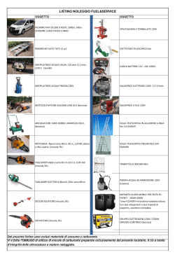
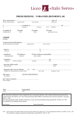
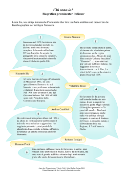
M A N UA L E D ’ U S O E I N S TA L L A Z I O N E
U S E A N D I N S TA L L AT I O N M A N UA L
MANUEL D'UTILISATION ET D'INSTALLATION
B E D I E N U N G S U N D
INSTALLATIONSANLEITUNG
MANUAL DE INSTRUCCIONES E INSTALACIÓN
VENTILCONVETTORI
FANCOIL
VENTILO-CONVECTEUR
GEBLÄSEKONVEKTOR
FAN COIL
FCX B-U-UA-UE
FCX 17 B -U-UA-UE
FCX 22 B -U-UA-UE
FCX 32 B -U-UA-UE
FCX 42 B -U-UA-UE
FCX 50 B -U-UA-UE
FCX 62 B -U-UE
FCX 82 B -U-UE
FCX 102 B -U-UE
FCX 17 ÷ 102 B
FCX 24 B -U-UA-UE
FCX 34 B -U-UA-UE
FCX 44 B -U-UA-UE
FCX 54 B -U-UA-UE
FCX 64 B -U-UE
FCX 84 B -U-UE
FCX 17 ÷ 54 UA
FCX 17 ÷ 54 U - UE
FCX 62 ÷ 102 U - UE
IFCXBULJ 1012 - 6456062_00
Sostituisce il • Replace • Remplace le n° • Ersetzt • Sustituye a: 6456053_04 / 1003
OSSERVAZIONI
Conservare i manuali in luogo asciutto, per evitare il deterioramento, per almeno 10 anni per eventuali riferimenti futuri.
Leggere attentamente e completamente tutte le informazioni contenute in questo manuale. Prestare particolarmente attenzione alle norme d’uso accompagnate dalle scritte
“PERICOLO” o “ATTENZIONE” in quanto, se non osservate,
possono causare danno alla macchina e/o a persone e cose.
Per anomalie non contemplate da questo manuale, interpellare
tempestivamente il Servizio Assistenza di zona.
L'apparecchio deve essere installato in maniera tale da rende-
re possibili operazioni di manutenzione e/o riparazione.
La garanzia dell'apparecchio non copre in ogni caso i costi
dovuti ad autoscale, ponteggi o altri sistemi di elevazione che
si rendesero necessari per effettuare gli interventi in garanzia.
AERMEC S.p.A. declina ogni responsabilità per qualsiasi danno
dovuto ad un uso improprio della macchina, ad una lettura
parziale o superficiale delle informazioni contenute in questo
manuale.
Il numero di pagine di questo manuale è: 32.
REMARKS
Store the manuals in a dry location to avoid deterioration, as
they must be kept for at least 10 years for any future reference.
All the information in this manual must be carefully read and
understood. Pay particular attention to the operating standards with “DANGER” or “WARNING” signals as failure to
comply with them can cause damage to the machine and/or
persons or objects.
If any malfunctions are not included in this manual, contact
the local After-sales Service immediately.
The apparatus must be installed in such a way that maintenan-
ce and/or repair operations are possible.
The apparatus's warranty does not in any case cover costs due
to automatic ladders, scaffolding or other lifting systems necessary for carrying out repairs under guarantee.
AERMEC S.p.A. declines all responsibility for any damage
whatsoever caused by improper use of the machine, and a partial or superficial acquaintance with the information contained
in this manual.
The number of pages in this manual is : 32.
REMARQUES
Conserver les manuels dans un endroit sec, afin d’éviter leur
détérioration, pendant au moins 10 ans, pour toutes éventuelles consultations futures.
Lire attentivement et entièrement toutes les informations contenues dans ce manuel. Prêter une attention particulière aux
normes d’utilisation signalées par les inscriptions “DANGER”
ou “ATTENTION”, car leur non observance pourrait causer un
dommage à l’appareil et/ou aux personnes et objets.
Pour toute anomalie non mentionnée dans ce manuel, contacter aussitôt le service après-vente de votre secteur.
Lors de l'installation de l'appareil, il faut prévoir l'espace
nécessaire pour les opérations d'entretien et/ou de réparation.
La garantie de l'appareil ne couvre pas les coûts dérivant de
l'utilisation de voitures avec échelle mécanique, d'échafaudages ou d'autres systèmes de levée employés pour effectuer des
interventions en garantie.
AERMEC S.p.A. décline toute responsabilité pour tout dommage dû à une utilisation impropre de l’appareil et à une lecture
partielle ou superficielle des informations contenues dans ce
manuel.
Ce manuel se compose de pages: 32.
HINWEISE
Bewahren Sie die Gebrauchsanleitungen mindestens 10 Jahre für eventuelles zukünftig e s N a ch s ch l a g e n a n e i n e m t r o ck e n e n O r t a u f .
Alle in diesem Handbuch enthaltenen Informationen
aufmerksam und vollständig lesen. Insbesondere auf die
Benutzungsanweisungen mit den Hinweisen "VORSICHT"
oder "ACHTUNG" achten, da deren Nichtbeachtung Schäden
am Gerät bzw. Sach- und Personenschäden zur Folge haben
kann.
Bei Betriebsstörungen, die in dieser Gebrauchsanweisung nicht
aufgeführt sind, wenden Sie sich umgehend an die zuständige
Kundendienststelle.
Das Gerät so aufstellen, dass Instandhaltungs- und/oder
Reparaturarbeiten durchgeführt werden können.
Die Garantie des Gerätes deckt in keinem Fall Kosten für
Feuerwehrleitern, Gerüste oder andere Hebesysteme ab, die
sich für die Garantiearbeiten als erforderlich erweisen sollten.
Die AERMEC S.p.A. übernimmt keine Haftung für Schäden aus
dem unsachgemäßen Gebrauch des Gerätes und der teilweisen
oder oberflächlichen Lektüre der in diesem Handbuch enthaltenen Informationen.
Die Seitenanzahl diese Handbuches ist: Nr. 32 Seiten
OBSERVACIONES
Guarde los manuales en un lugar seco para evitar su deterioro,
al menos durante 10 años, por si fuera posible consultarlos en
el futuro.
Leer atenta y completamente todas las informaciones contenidas en este manual. Preste particular atención a las normas de uso acompañadas de las indicaciones “PELIGRO” o
“ATENCIÓN” puesto que, si no se cumplen, pueden causar
el deterioro de la máquina y/o daños personales y materiales.
En caso de anomalías no contempladas en este manual, contacte inmediatamente con el Servicio de Asistencia de su zona.
El aparato debe ser instalado de manera que haga posibles las
2
IFCXBULJ 1012 - 6456062_00
operaciones de mantenimiento y/o reparación.
En cualquier caso, la garantía del aparato no cubre los costes
derivados del uso de escaleras automáticas, andamios u otros
sistemas de elevación necesarios para efectuar las intervenciones en garantía.
AERMEC S.p.A. declina cualquier responsabilidad por cualquier daño debido a un uso impropio de la máquina, o bien a
una lectura parcial o superficial de las informaciones contenidas en este manual.
Número de páginas de este manual: 32
INDICE
DICHIARAZIONE DI CONFORMITÀ
Trasporto • Simboli di sicurezza
Informazioni importanti e manutenzione • Limiti di funzionamento • Imballo • Utilizzo
Installazione dell’unità • Collegamenti elettrici • Rotazione batteria
Disegni
Dati dimensionali
Schemi elettrici
SOLUZIONE DEI PROBLEMI
4
5
6
7
16
17
20
31
INDEX
4
5
8
9
16
17
20
31
DECLARATION OF CONFORMITY
Carriage • Safety symbol
Important information and maintenance • Operating limits • Packaging • Use
Unit installation • Electrical connections • Battery rotation
Sketches
Dimensions
Wiring diagram
TROUBLE SHOOTING
INDEX
CERTIFICAT DE CONFORMITE
Transport • Simboles de securite
Informations importantes et entretien • Limites de fonctionnement • Emballage • Utilisation
Installation de l'unité • Raccordements électriques • Rotation batterie
Dessin
Dimensions
Schemas electriques
SOLUTION DES PROBLEMES
4
5
10
11
16
17
20
31
INDEX
KONFORMITÄTSERKLÄRUNG
Transport • Sicherheitssymbole
Wichtige Informationen und Wartung • Betriebsbereich • Verpackung • Gebrauch
Installation der Einheit • Elektrische Anschlüsse • Umdrehen des Wärmetauschers
Designs
Abmessungen
Schaltpläne
PROBLEMLÖSUNG
4
5
12
13
16
17
20
31
ÍNDICE
DECLARACIÓN DE CONFORMIDAD
Transporte • Símbolos de seguridad
Información importante y mantenimiento • Lìmites de funcionamiento • Embalaje • Uso
Instalación de la unidad • Conexiones eléctricas • Giro batería
Diseños
Dimensiones
Esquemas eléctricos
SOLUCIÓN DE PROBLEMAS
IFCXBULJ 1012 - 6456062_00
4
5
14
15
16
17
20
31
3
FCX
B - U - UA- UE
AERMEC S.p.A.
I-37040 Bevilacqua (VR) Italia – Via Roma, 996
Tel. (+39) 0442 633111
Telefax (+39) 0442 93730 – (+39) 0442 93566
www .aermec. com - info @aermec. com
DICHIARAZIONE DI CONFORMITÀ
Noi, firmatari della presente, dichiariamo sotto la nostra esclusiva
responsabilità, che il prodotto:
VENTILCONVETTORE
serie FCX
al quale questa dichiarazione si riferisce è conforme alle seguenti norme
armonizzate:
-
CEI EN 60335-2-40
CEI EN 62233
-
CEI EN 55014-1
CEI EN 55014-2
CEI EN 61000-6-1
CEI EN 61000-6-3
soddisfando così i requisiti essenziali delle seguenti direttive:
- Direttiva Bassa Tensione: LVD 2006/95/CE
- Direttiva Compatibilità Elettromagnetica: EMC 2004/108/CE
- Direttiva Macchine: 2006/42/CE
FCX CON ACCESSORI
E’ fatto divieto di mettere in servizio il prodotto dotato di accessori
non di fornitura Aermec.
CONFORMITY DECLARATION
We the undersigned declare, under our own exclusive responsibility,
that the product:
FAN COIL
FCX series
to which this declaration refers, complies with the following standardised
regulations:
-
EN 60335-2-40
EN 62233
-
EN 55014-1
EN 55014-2
EN 61000-6-1
EN 61000-6-3
thus meeting the essential requisites of the following directives:
- Low Voltage Directive: LVD 2006/95/EC
- Electromagnetic Compatibility Directive: EMC 2004/108/EC
- Machinery Directive: 2006/42/EC
FCX WITH ACCESSORIES
It is not allowed to use the unit equipped with accessories not supplied by Aermec.
KONFORMITÄTSERKLÄRUNG
CERTIFICAT DE CONFORMITÉ
Nous soussignés déclarons sous notre exclusive responsabilité que le
produit:
VENTILO-CONVECTEURS
série FCX
auquel cette déclaration fait référence, est conforme aux normes
harmonisées suivantes:
- EN 60335-2-40
- EN 55014-1
- EN 62233
- EN 55014-2
- EN 61000-6-1
- EN 61000-6-3
Wir, die hier Unterzeichnenden, erklären auf unsere ausschließlich
Verantwortung, dass das Produkt:
GEBLÄSEKONVEKTOR
der Serie FCX
auf das sich diese Erklärung bezieht, den folgenden harmonisierten
Normen entspricht:
satisfaisant ainsi aux conditions essentielles des directives suivantes:
- Directive Basse Tension: LVD 2006/95/CE
- Directive compatibilité électromagnétique: EMC 2004/108/CE
- Directive Machines: 2006/42/CE
FCX PLUS ACCESSOIRES
Il est interdit de faire fonctionner l'appareil avec des accessoires qui ne
sont pas fournis de Aermec.
womit die grundlegenden Anforderungen folgender Richtlinien erfüllt werden:
- Niederspannungsrichtlinie: LVD 2006/95/EG
- Richtlinie zur elektromagnetischen Verträglichkeit: EMC 2004/108/EG
- Maschinenrichtlinie: 2006/42/EG
FCX + ZUBEHÖR
Falls das Gerät mit Zubehörteilen ausgerüstet wird, die nicht von
Aermec geliefert werden, ist dessen Inbetriebnahme solange untersagt.
-
EN 60335-2-40
EN 62233
-
EN 55014-1
EN 55014-2
EN 61000-6-1
EN 61000-6-3
DECLARACIÓN DE CONFORMIDAD
Los que suscriben la presente declaran bajo la propia y exclusiva
responsabilidad que el conjunto en objeto, definido como sigue:
FAN COIL
serie FCX
al que esta declaración se refiere, está en conformidad a las siguientes
normas armonizadas:
-
EN 60335-2-40
EN 62233
-
EN 55014-1
EN 55014-2
EN 61000-6-1
EN 61000-6-3
al que esta declaración se refiere, está en conformidad a las siguientes
normas armonizadas:
- Directiva de Baja de Tensión: LVD 2006/95/CE
- Directiva Compatibilidad Clectromagnétic: EMC 2004/108/CE
- Directiva Máquinas: 2006/42/CE
FCX CON ACCESORIOS
Está prohibido poner en marcha el producto con accesorios
no suministrados por Aermec.
La persona autorizzata a costituire il fascicolo tecnico è: / The person authorized to compile the technical file is: / La personne autorisée à constituer le dossier technique est: / Die Person berechtigt, die technischen Unterlagen zusammenzustellen:
Pierpaolo Cavallo
I-37040 Bevilacqua (VR) Italia - Via Roma, 996
Bevilacqua, 16/12/2010
La Direzione Commerciale – Sales and Marketing Director
Luigi Zucchi
TRASPORTO • CARRIAGE • TRANSPORT • TRANSPORT • TRANSPORTE
NON bagnare. Tenere al riparo
dalla pioggia
Do NOT wet
CRAINT l’humidité
Vor Nässe schützen
NO mojar
NON calpestare
Do NOT step
NE PAS marcher sur cet emballage
Nicht betreten
NO pisar
Sovrapponibilità: controllare sull’imballo per conoscere il numero di macchine impilabili
Stacking: control the packing to know the number of machines that can be stacked
Empilement: vérifier sur l’emballage pour connaître le nombre d’appareils pouvant être empilés
Stapelung: Die Anzahl der stapelbaren Geräte, wird durch die Symbole auf den Verpackungen ermittelt
Apilamiento: observe en el embalaje para saber cuántos equipos pueden apilarse
NON lasciare gli imballi sciolti durante il trasporto - Non rovesciare
Do NOT leave loose packages during transport
ATTACHER les emballages pendant le transport
Die Verpackungen nicht ungesichert transportieren
NO lleve las cajas sueltas durante el transporte
>25Kg
NON trasportare la macchina da soli se il suo peso supera i 25 Kg
DO NOT handle the machine alone if its weight is over 25 Kg
NE PAS transporter tout seul l’appareil si son poids dépasse 25 Kg
Das Gerät NICHT alleine tragen, wenn sein Gewicht 25 Kg überschreitet
NO maneje los equipos en solitario si pesan más de 25 kg
Fragile, maneggiare con cura
Fragile, handle with care
Fragile, manipuler avec soin
Zerbrechlich, mit Sorgfalt behandeln
Frágil, manejar con cuidado
Freccia: alto
Arrow: high
Flèche: haut
Pfeil: hoch
Flecha: alto
SIMBOLI DI SICUREZZA • SAFETY SYMBOL • SIMBOLES DE SECURITE
SICHERHEITSSYMBOLE • SÍMBOLOS DE SEGURIDAD
Pericolo:
Tensione
Pericolo:
Organi in movimento
Pericolo!!!
Danger:
Power supply
Danger:
Movings parts
Danger!!!
Danger:
Tension
Danger:
Organes en mouvement
Danger!!!
Gefahr !
Spannung
Gefahr !
Rotierende Teile
Gefahr!!!
Peligro:
Tensión
Peligro:
Elementos en movimiento
Peligro!!!
IFCXBULJ 1012 - 6456062_00
5
IMPORTANT INFORMATION AND MAINTENANCE
English
WARNING: The fancoil is connected
to the power supply and a water circuit. Operations performed by persons
without the required technical skills can
lead to personal injury to the operator
or damage to the unit and surrounding
objects.
WARNING
Avoid that the device is used by children
or incompetent persons without
appropriate supervision; also note that
the unit should not be used by children
as a game.
POWER THE FANCOIL WITH SINGLEPHASE 230 V ONLY
Use of other power supplies could cause
permanent damage to the fancoil.
N E V E R U S E T H E FA N C O I L F O R
APPLICATIONS FOR WHICH IT WAS
NOT DESIGNED
Do not use the fancoil in husbandry
applications (e.g. incubation).
AIR THE ROOM
Periodically air the room in which the
fancoil has been installed; this is particularly important if the room is occupied
by many people, or if gas appliances or
sources of odours are present.
C O R R E C T LY
ADJUST
THE
TEMPERATURE
Room temperature should be regulated
to ensure maximum comfort to persons
present, particularly in the case of the
elderly, infants and invalids. Prevent
temperature fluctuations between
indoors and outdoors greater than 7 °C
during summer.
Note that very low temperatures during
summer will lead to greater electricity
consumption.
ORIENT AIR FLOW CORRECTLY
Air delivered by the fancoil should not
be oriented directly at people; even if air
temperature is greater than room temperature, it can cause a cold sensation
and consequently discomfort.
DURING UNIT OPERATION
Always leave the filter on the fancoil
during operation (otherwise dust in the
air could soil the surface of the coil).
IT IS NORMAL
During cooling, water vapour may be
present in the air delivery of the fan coil.
In the heating function it might be possible to hear a slight hiss around the
fan coil. Sometimes the fan coil might
give off unpleasant smells due to the
accumulation of dirt in the air of the
environment (especially if the room is
not ventilated regularly, clean the filter
more often).
During the operation, there could be
noises and creaks inside the device, due
to the various heat expansions of the
elements (plastic and metallic), but this
does not indicate any malfunctioning
and does not cause damage to the unit
unless the maximum input water temperature is exceeded.
Do not use chemical products or solvents to clean any part of the fancoil.
Do not splash water on interior or exterior surfaces of the fancoil; danger of
short circuit.
PERIODICALLY CLEAN THE FILTER
Frequent cleaning of the filter will ensure
more efficient unit operation.
Check whether the filter requires cleaning; if it is particularly dirty, clean it
more often.
Clean the filter frequently. Use a vacuum
cleaner to remove built up dust. Avoid
water or detergents if possible since they
greatly accelerate loss of the filter's electrostatic charge.
After cleaning and drying the filter, fit it
on the fancoil by following the removal
procedure in reverse order.
SPECIAL CLEANING
The removable drip tray and fan volute
ensure thorough cleaning of the unit (by
specifically trained personnel), essential for installations in venues subject
to crowding or in those with special
hygiene requirements.
MAINTENANCE
DO NOT USE HOT WATER
When cleaning the indoor unit, use rags
or soft sponges soaked in warm water
(no higher than 40°C).
OPERATING LIMITS
Maximum water inlet temperature
Maximum working pressure
80 °C
8 bar
Minimum average water temperature
To prevent the formation of condensation on the exterior of the unit while
the fan is operating, the average water
temperature should not drop beneath
the limits shown in the table below,
determined by the ambient conditions.
These limits refer to unit operation with
fan at minimum speed. Note that condensation may form on the exterior of
the unit if cold water circulates through
the coil while the fan is off for prolonged
periods of time, so it is advisable to fit
the additional three-way valve.
Temperature of the air in the room with dry bulb °C
MINIMUM AVERAGE WATER TEMPERATURE
Temperature of the air in the room
with wet bulb
21
23
25
27
29
31
15
3
3
3
3
3
3
17
3
3
3
3
3
3
19
3
3
3
3
3
3
21
6
5
4
3
3
3
23
-
8
7
6
5
5
PACKING
The units are shipped in cardboard box standard packing and
polystirene shells.
USE
Consult the manual of the control panel for the installation and use
instructions.
8
IFCXBULJ 1012 - 6456062_00
Versions:
B
(vertical installation, without
control panels).
U-UA (horizontal and vertical
installation, without control
panels).
UE (horizontal and vertical installation, with direct expansion
coil, without control panels).
to 50.
- Use expansion plugs (not supplied) to
secure the unit to the wall or ceiling, as
shown in figures 5 and 6.
To install hanging units with the AMP
brackets, proceed as follows:
- fit the 4 brackets (1 in Fig. 8) to the sides
of the unit; insert the upper tab in the slot,
then secure the lower part to the contact
block by means of the screws supplied;
- secure the flanges (2) to the ceiling by
means of expansion plugs (not supplied); for
the positions between the flanges and the
contact block, see the dimensional data.
- Make hydraulic connections.
Refer to the dimensional data for the position
and diameter of the hydraulic connectors.
Insulate water lines adequately or fit the
condensate drainage tray (available as an
accessory) to prevent dripping during cooling applications.
In case of horizontal installation, fit the
condensate discharge pipe (supplied separately) following the indications shown in
picture 10. The connection between pipe
and drip tray must be sealed with silicone.
The condensate drainage system should
be of an adequate size and be positioned
to favour runoff (min. 1% slope). If condensate is discharged into the sewage system, install a siphon to prevent return of
unpleasant odour into the room.
- Make the electrical connections as shown
in the wiring diagrams.
- Remount the cover, or the front pannel,
connect the ambient sensor or the microswitch (if present).
- CAUTION: Keep separate electrical connections from water connections.
Water connections and drain should be on
the side opposite of the electrical connections.
The assembling place must be chosen so
that the max. and min. room temperature
limit is respected 0÷45°C (<85% U.R.).
The control panel may not be fitted on a
metal wall unless this is permanently connected to a grounded outlet.
The control panels consist simply of electric circuits connected to the mains voltage of 230V; all the inputs for the sensors and controls must therefore be correspondingly insulated for this voltage.
Some control panels are fitted with a room
temperature probe and/or a water temperature probe. In addition, it is possible to connect an external contact to the
internal control board (EX), allowing the
remote control of the fan coil; consult the
recapitulatory table and the manuals of
the individual panels to select the most
suitable model.
The minimum water temperature probe
makes it possible to stop the ventilation
automatically if the temperature of the
input water to the coil falls below 39°C.
In installations with a three-way valve, the
minimum water temperature probe must
be relocated from its standard mounting
in the coil to the delivery hose upstream
of the valve.
When relocating the water temperature probe, the standard probe must be
replaced with an accessory SW3 probe,
fitted with a cable of suitable length.
CAUTION: given that it is powered to
230 VAC, the probe has double insulation.
When installing remote control panels
with FCX-U version fancoils, observe the
relative wiring diagram; configure the
microswitch (MS) in the panel (controlling
the opening of the delivery grille) in series
on the panel power supply.
Multifunction electronic thermostats are
supplied ready to operate in standard configuration, though can be adjusted to the
specific operating requirements by means
of the internal dip-switches.
Customised functions vary between models; for this reason, consult the relative
manuals.
WARNING: check whether the installation has been carried out correctly.
Follow the checking procedures indicated
in the manuals of the control panels.
– remove the push-outs (6) on the right
side;
– rotate the coil (5), then secure it in the
new position with the screws previously
removed;
– remount the coil cover sheet (4) and
secure it with screws, then insert the
plastic plugs (7) supplied in the openings
left free by the hydraulic connections;
all trays are designed to collect condensate on both sides. In the case of vertical installation, for condensate drainage
on the right side, position the drainage
union to the right (8).
– to move condensate drainage to the right
of the unit, reverse discharge of the tray
(3) (if present), then transfer the drainage
line (8) to the right;
– slide out the electrical connections from
the right side, remove the push-out, then
transfer the cable guide (9) from the right
to the left side;
– transfer the electrical connections to the
left side through the cable guide (9);
– move the terminal block (10) and the
ground jumper connection (11) to the
left side of the unit;
CAUTION: check that the power supply
is disconnected before performing operations on the unit.
CAUTION: wiring connections installation of the fancoil and relevant accessories
should be performed by a technician who
has the necessary technical and professional expertise to install, modify, extend
and maintain plants and who is able to
check the plants for the purposes of safety
and correct operation.
The fancoil should be installed in such a
way as to facilitate routine (filter cleaning)
and special maintenance operations, as
well as access to the air breather valve on
the side of the unit frame (connector side).
To install the unit, proceed as follows:
- Extract the air filter (FCX - AS model
only).
- Remove the housing by loosening the
screws (Figures 1 and 2), or the rear cover
panel in the case of wall models, sizes 17
ELECTRICAL CONNECTIONS
CAUTION: make sure that electrical
power to the machine has been turned off
before making electrical connections.
CAUTION: wiring operations and installation of the fancoil and relative accessories should be performed by specialised
personnel only.
CONNECTION CABLE SPECIFICATIONS
Use H05V-K or N07V-K type with
300/500 V insulation piped or ducted.
All cables must be piped or ducted until
they are not placed inside the fan coil.
The cables coming out of the pipe/duct
must not be subjected to stretch or twist.
They must be protected from weather conditions.
Stranded wires may only be used in connection with terminating sleeves. It must
be ensured that all individual wires are
correctly inserted in the sleeve.
All wiring diagrams are constantly updated. Please refer to the ones supplied with
the unit.
To protect fan coils against short circuits,
always fit the power cable to the units
with 2A 250V (IG) thermo-magnetic allpole switches with a minimum contact
gap of 3 mm.
ROTATING THE COIL
If connection of utilities to the unit requires
rotation of the coil, remove the cover or
the front pannel, then proceed as follows
(Fig. 9):
– remove the screw securing the control
panel (if present) to the right side of the
unit, then remove it after electrical disconnection;
– remove the condensate tray (3) (not
present on FCX - B version);
– remove the coil cover sheet (4) by
removing the screws;
– remove the screws securing the coil (5),
then remove it;
IFCXBULJ 1012 - 6456062_00
9
English
UNIT INSTALLATION
Fig. 2
Fig. 5
Fig. 6
2
B
B
B
A
A
A
1
Fig. 8
Fig. 7
4
5
6
7
11
8
10
9
3
Fig. 9
Fig. 11
16
IFCXBULJ 1012 - 6456062_00
Ø est. 20,5mm
Fig. 10
Fig. 12
DATI DIMENSIONALI • DIMENSIONS • DIMENSIONS • ABMESSUNGEN • DIMENSIONES [mm]
FCX U - UE
FCX B - U - UE - UA
D
Mod. 17 - 22 - 32 - 42 - 50
24 - 34 - 44 - 54
Mod. 62 - 82 - 102
64 - 84
FCX - U - UE
FCX - U - UE
Mod. 17 - 22 - 32 - 42 - 50
Mod.
24 - 34 - 44 - 54
FCX B
Mod. 62 - 64 - 82 - 84 - 102
Mod. 17 - 22 - 24 - 32 - 34 - 42 - 44 - 50 - 54
62 - 64 - 82 - 84
FCX UA Mod. 17 - 22 - 24 - 32 - 34 - 42 - 44 - 50 - 54
FCX (3R)
17
22
32
42
50
62
82
102
FCX (4R)
-
24
34
44
54
64
84
-
A
[mm]
520
520
520
520
520
-
-
-
B
[mm]
640
750
980
1200
1200
1320
1320
1320
C
[mm]
220
220
220
220
220
220
220
220
D
[mm]
490
490
490
490
490
590
590
590
Peso
[kg]
13
15
20
24
24
34
34
34
50
50
100
IFCXBULJ 1012 - 6456062_00
17
DATI DIMENSIONALI • DIMENSIONS • DIMENSIONS • ABMESSUNGEN • DIMENSIONES [mm]
FCX 17 - 22 - 32 - 42 - 50
24 - 34 - 44 - 54
3R
FCX 62 - 82 - 102
64 - 84
3R+1R
3R
3R+1R
FCX (3R)
17
22
32
42
50
62
82
102
FCX (4R)
-
24
34
44
54
64
84
-
B
[mm]
412
522
753
973
973
1122
1122
1122
C
[mm]
330
440
671
891
891
1102
1102
1102
[kg]
11
13
18
22
22
33
33
33
Peso
Attacchi idraulici
FCX (3R)
BV (1R)
FCX (4R)
17
22
32
42
50
62
82
102
1/2”
1/2”
1/2”
3/4”
3/4”
3/4”
3/4”
3/4”
17
22
32
42
50
62
82
102
1/2”
1/2”
1/2”
1/2”
1/2”
1/2”
1/2”
1/2”
-
-
24
34
44
54
64
84
3/4”
3/4”
3/4”
3/4”
3/4”
3/4”
BV = Batteria a caldo (1R), disponibile come accessorio per FCX (3R)
18
IFCXBULJ 1012 - 6456062_00
DATI DIMENSIONALI • DIMENSIONS • DIMENSIONS • ABMESSUNGEN • DIMENSIONES [mm]
Installazione con supporti AMP (accessori) • Installation with AMP brackets (accessories)
Installation avec supports AMP (accessories) • Installation mit AMP halterung (zubehöre)
Instalación con soportes AMP (accesorios)
FCX 17 - 22 - 32 - 42 - 50 U / UE
24 - 34 - 44 - 54 U / UE
FCX 62 - 82 -102 U / UE
64 - 84 U / UE
FCX (3R)
17
22
32
42
50
62
82
102
FCX (4R)
-
24
34
44
54
64
84
-
A
[mm]
640
750
981
1201
1201
1322
1322
1322
B
[mm]
445
555
786
1006
1006
1127
1127
1127
C
[mm]
490
600
831
1051
1051
1172
1172
1172
D
[mm]
95,5
95,5
95,5
95,5
95,5
95,5
95,5
95,5
E
[mm]
54,5
54,5
54,5
54,5
54,5
54,5
54,5
54,5
F
[mm]
144,5
144,5
144,5
144,5
144,5
144,5
144,5
144,5
G
[mm]
103,5
103,5
103,5
103,5
103,5
103,5
103,5
103,5
In caso di inversione degli attacchi idraulici, scambiare tra loro le seguenti quote: D con E, F con G.
In case of inversion hydraulic connections, invert D with E, F with G.
En cas d’inversion des raccords hydrauliques, inverser les cotes D avec E, F avec G.
Bei der Anschlüßenumstellung, die Quoten D und E, F und G, miteinander auswechseln.
Si desea invertir el lado de las conexiones hidráulicas, intercambie D por E y F por G.
FCX 17 ÷ 54 3R
FCXI 62 - 102 3R
FCX 17 ÷ 54 1R
FCX 17 ÷ 54 1R
IFCXBULJ 1012 - 6456062_00
19
SCHEMI ELETTRICI • WIRING DIAGRAMS • SCHEMAS ELECTRIQUES • SCHALTPLÄNE • ESQUEMAS ELÉCTRICOS
LEGENDA • READING KEY • LEGENDE • LEGENDE • LEYENDA
AL = Alimentatore 12V
Power supply 12V
Alimentation electrique 12V
Spannung 12V
Alimentador
MV = Motore ventilatore • Fan motor
Moteur ventilateur • Ventilatormotor
Motor del ventilador
PE = Collegamento a terra
GND Earth connection
Mise à terre
Erdanschluss
Toma de tierra
CE = Contatto esterno
EX External contact
Contact extérieur
Externer Kontakt
Contacto externo
RE = Resistenza elettrica • Electric heater
RX = Résistance électrique • Elt. Heizregister
Resistencia eléctrica
CN = Connettore
Connector
Connecteur
Schütz
Conector
SA = Sonda ambiente • Room sensor
Sonde ambiante • Raumtemperaturfuhler
Sonda ambiente
SC = Scheda di controllo
Electronic control board
Platine de contrôle • Steuerschaltkreis
Tarjeta electrónica de control
CRE= Contattore resistenza elettrica
Electric heater contactor
Contacteur résistance eléctrique
El. Heizregister-Schutz
Contactor de la resistencia eléctrica
F
SW = Sonda minima temperatura acqua
Water low temperature sensor
Sonde minimum temp. eau
Wasserfühler
Sonda temperatura mínima del agua
= Fusibile • Fuse • Fusible
Sicherung • Fusible
IG = Interruttore generale • Main switch
Interupteur général • Hauptschalter
Interruptor general
TR = Trasformatore • Transformer
Transformateur
Transformator • Transformador
M = Morsettiera • Terminal board
Boitier • Klemmleiste
Placa de bornes
TSR = Termostato a riarmo automatico
Automatic resetting thermostat
Thermostat à réarmement automatique
Thermostat automatischer Entriegelung
Termostato de rearme automático
ML = Motore aletta
Louvre motor
Moteur deflecteur
Motor- Umlenkklappe
Lamas motorizadas
TSRM= Termostato a riarmo manuale
Manual resetting thermostat
Thermostat à réarmement manuel
Thermostat manueller Entriegelung
Termostato de rearme manual
MS = Microinterruttore griglia
(Solo per i modelli che ne sono provvisti)
Louvre microswitch
(Only for the appropriate models)
Micro-interrupteur grille
(Uniquement pour les modèles qui en sont fournis)
Mikroschalter Gitter
(Nur bei Modellen, die damit ausgestattet sind)
Microinterruptor de la rejilla de impulsión
(Sólo para los modelos que lo incluyen)
5
7
8
9
BL
NE
MA
RO
5
1
2
3
4
6
5
1
2
3
4
6
MIN
4
MED
3
6
MAX
2
Sez. 1,5 mm2
BL
= Componenti forniti optional
Optional components
Composants en option
Optionsteile
Componentes opcionales
= Collegamenti da eseguire in loco
On-site wiring
Raccordements à effectuer in situ
Vor Ort auszuführende Anschlüsse
Cableado in situ
AR = Arancio • Orange • Orange • Orange • Naranja
BI = Bianco • White • Blanc • Weiss • Blanco
BL = Blu • Blue • Bleu • Blau • Azul
GR = Grigio • Grey • Gris • Gray • Gris
MA = Marrone • Brown • Marron • Braun • Marrón
NE = Nero • Black • Noir • Schwarz • Negro
RO = Rosso • Red • Rouge • Rot • Rojo
VE = Verde • Green • Vert • Grün • Verde
VI = Viola • Violet • Violet • Violet • Violeta
VC = Valvola solenoide caldo
Solenoid valve hot
Vanne magnétique chaud
Magnetventil Heizbetrieb
Válvula solenoide para calor
(62 - 82 - 102 only) Universal, without controls
(seulement 62 - 82 - 102) Universel sans commandes
(nur 62 - 82 - 102) Universalgerät ohne Steuerungen
(sólo 62 - 82 - 102) Universal sin panel de mandos
1
= Componenti non forniti
Components not supplied
Composants non fournis
Nicht lieferbare Teile
Componentes no suministrados
VCF=Valvola solenoide • Solenoid valve
Vanne solenoide • Magnetventil
Válvula solenoide
FCX - UA
FCX - U (solo 62 - 82 - 102) Universale senza comandi
M
FCX
VF = Valvola solenoide freddo
Solenoid valve cold
Vanne magnétique froid
Magnetventil Kühlbetrieb
Válvula solenoide para frío
NE
(escluso 62 - 82 - 102) Universale senza comandi
(except 62 - 82 - 102) Universal, without controls
(esclus 62 - 82 - 102) Universel sans commandes
(ohne 62 - 82 - 102) Universalgerät ohne Steuerungen
(excluidos 62 - 82 - 102) Universal sin panel de mandos
10
MA
1
FCX - U
RO
M
MV
IG
PE
L N
230V ~ 50Hz
Gli schemi elettrici sono soggetti ad un continuo aggiornamento, è obbligatorio quindi fare riferimento a quelli a bordo macchina.
All
wiring
diagrams
are
constantly
updated.
Please
refer
to
the
ones
supplied
with
the
unit.
Nos schémas électriques étant constamment mis à jour, il faut absolument se référer à ceux fournis à bord de nos appareils.
Die Schaltpläne werden ständig aktualisiert, deswegen muss man sich stets auf das mit dem Gerät gelieferte Schaltschema beziehen.
El cableado de las máquinas es sometido a actualizaciones constantes. Por favor, para cada unidad hagan referencia a los esquemas suministrados con la misma.
20
IFCXBULJ 1012 - 6456062_00
SCHEMI ELETTRICI • WIRING DIAGRAMS • SCHEMAS ELECTRIQUES • SCHALTPLÄNE • ESQUEMAS ELÉCTRICOS
VMF_E1
VMF-E2/E4
VMF_E0
VMF-E2/E4
VMF-E2
VMF-E2H
VMF-E4
CN22
CN25
CN26
CN19
CN18
CN21
CN28
+
(SP) CE
CN10-B CN10-A
1
1
C1
ON
CN23
CN8
CN17
DIP
ON
DIP
SLOT EXPANSION
1
CN27
123 456 7 8
CN8
CN16
2- GND
SP CE
5-GND-Pan
4-V+-Pan
CN10-B CN10-A
1
1
CN17
MS
1 2345 67 8
+ C8
3- GND-485
CN27
1- A-485
2- B- 485
1
+ C2
T1
2- GND
1-TX-RX
MS
1-TX-RX
VMF-E2
VMF-E2H
VMF-E4
CN9
JP1
C7
SA
L
230V 50Hz
SA
1
SW
SA
10k
V1
CN11
V2
MIN
V3
MED
N
MAX
N
N
Y1
CN1
PF2
1
VC
N
CN7-B CN7-A
M
MV
IG
10k
BL NE MA RO
N
Y2
L
SW
1
SW
VF
VMF-E0
SW
V1
CN11
V2
MIN
V3
MED
N
MAX
N
CN1
T1
SW1
PF2
CN7-B CN7-A
N
Y1
N
Y2
L
CN9
JP1
VMF-E1
C1
SW1
CN14
VC/F
10k
BL NE MA RO
PE
M
MV
1
10k
IG
L
SA
PE
N
Dis. 5152700_00
230V 50Hz
MODBUS
12Vdc
VMF-E2
VMF-E2H
VMF-E4
0Vdc
TTL
VMF-E1
VMF-E5
VMF-E2/E4
SP CE
5-GND-Pan
4-V+-Pan
3- GND-485
CN10-B CN10-A
1
1
CN17
CN8
CN16
ON
DIP
SLOT EXPANSION
1 2345 67 8
+ C8
1- A-485
2- B- 485
CN27
MS
2- GND
1-TX-RX
1
+ C2
T1
CN22
CN25
CN26
CN19
CN18
CN21
CN28
VMF-E1
SW
V1
CN11
V2
SA
1
MIN
V3
MED
N
MAX
N
CN1
CN14
SW1
PF2
CN7-B CN7-A
N
Y1
N
Y2
L
SW1
CN9
JP1
CN23
C1
(E5)
SW
VF
M
MV
IG
L
VC
N
230V 50Hz
PE
10k
BL NE MA RO
1
10k
SA
Dis. 5152600_02
Gli schemi elettrici sono soggetti ad un continuo aggiornamento, è obbligatorio quindi fare riferimento a quelli a bordo macchina.
All
wiring
diagrams
are
constantly
updated.
Please
refer
to
the
ones
supplied
with
the
unit.
Nos schémas électriques étant constamment mis à jour, il faut absolument se référer à ceux fournis à bord de nos appareils.
Die Schaltpläne werden ständig aktualisiert, deswegen muss man sich stets auf das mit dem Gerät gelieferte Schaltschema beziehen.
El cableado de las máquinas es sometido a actualizaciones constantes. Por favor, para cada unidad hagan referencia a los esquemas suministrados con la misma.
IFCXBULJ 1012 - 6456062_00
21
SCHEMI ELETTRICI • WIRING DIAGRAMS • SCHEMAS ELECTRIQUES • SCHALTPLÄNE • ESQUEMAS ELÉCTRICOS
VMF-E0 (master + slave)
(---------------------------------------------------------------------------------------------------------- 30 m MAX ------------------------------------------------------------------------------------------------------)
E0/1 Slave ÷5
VMF-E2
VMF-E2H
VMF-E4
Only master
MS
MS
Slave 1
+
(SP) CE
CN10-B CN10-A
1
1
123 456 7 8
2- GND
1-TX-RX
TTL
DIP
C1
ON
ON
DIP
C1
CN8
CN17
VMF-E0
VMF-E0
T1
CN9
JP1
CN9
JP1
T1
1
CN27
(SP) CE
CN17
+
E0 Master
CN10-B CN10-A
1
1
CN8
123 456 7 8
1
CN27
1-TX-RX
E0 Master
2- GND
TTL
Master
C7
SW
PF2
N
N
V3
V2
V1
CN11
CN7-B CN7-A
SA
1
MIN
N
MED
1
MAX
MAX
L
SA
N
Y1
V1
Y2
V2
CN11
V3
MIN
N
CN1
PF2
N
CN1
N
Y1
CN7-B CN7-A
MED
N
Y2
L
SW
C7
SW
VC/F
SW
10k
BL NE MA RO
VC/F
M
M
1
MV
Dis. 5152700_00
230V 50Hz
VMF-E1 (master + slave)
VMF-E5
VMF-E2/E4
SA
10k
IG
PE
N
1
MV
SA
10k
L
L
PE
N
Dis. 5152700_00
230V 50Hz
(---------------------------------------------------------------------------------------------------------- 30 m MAX ------------------------------------------------------------------------------------------------------)
E0/1 Slave ÷5
Master
TTL
VMF-E2
VMF-E2H
VMF-E4
TTL
IG
10k
BL NE MA RO
Slave 1
MODBUS
12Vdc
0Vdc
(E5)
MS
CN28
VMF-E1
VMF-E1
N
SA
CN7-B CN7-A
N
V3
V2
MAX
1
V1
SA
L
VC
N
230V 50Hz
PE
VF
M
MV
IG
1
10k
SA
1
SW
10k
BL NE MA RO
SW1
CN14
SW1
PF2
SW
VF
1 2345 67 8
SP CE
CN10-B CN10-A
1
1
5-GND-Pan
DIP
CN28
Y2
L
CN1
V1
4-V+-Pan
ON
SW
V2
CN11
V3
3- GND-485
CN21
MIN
N
1- A-485
2- B- 485
CN18
C1
MAX
N
CN1
CN19
CN14
SW1
PF2
CN7-B CN7-A
N
Y1
N
Y2
L
MED
C1
SW1
CN26
SW
CN21
CN25
CN11
CN18
CN22
CN9
JP1
CN19
CN23
MED
CN26
N
CN25
CN8
CN16
SLOT EXPANSION
N
Y1
CN22
CN9
JP1
CN23
CN17
MIN
ON
DIP
SLOT EXPANSION
+ C8
2- GND
1-TX-RX
SP CE
5-GND-Pan
4-V+-Pan
CN16
CN27
T1
1 2345 67 8
CN17
CN8
1
+ C2
CN10-B CN10-A
1
1
+ C8
3- GND-485
CN27
1- A-485
2- B- 485
1
+ C2
T1
2- GND
1-TX-RX
MS
M
MV
IG
L
VC
N
230V 50Hz
10k
BL NE MA RO
1
10k
SA
PE
Gli schemi elettrici sono soggetti ad un continuo aggiornamento, è obbligatorio quindi fare riferimento a quelli a bordo macchina.
All
wiring
diagrams
are
constantly
updated.
Please
refer
to
the
ones
supplied
with
the
unit.
Nos schémas électriques étant constamment mis à jour, il faut absolument se référer à ceux fournis à bord de nos appareils.
Die Schaltpläne werden ständig aktualisiert, deswegen muss man sich stets auf das mit dem Gerät gelieferte Schaltschema beziehen.
El cableado de las máquinas es sometido a actualizaciones constantes. Por favor, para cada unidad hagan referencia a los esquemas suministrados con la misma.
22
IFCXBULJ 1012 - 6456062_00
SCHEMI ELETTRICI • WIRING DIAGRAMS • SCHEMAS ELECTRIQUES • SCHALTPLÄNE • ESQUEMAS ELÉCTRICOS
PX2
PXBI + VCF
commutatore a distanza
remote switch
commutateur à distance
Fernumschalter
conmutador remoto
2 tubi pannello PXBI a bordo macchina
2 tubes PXBI panel on board machine
2 tuyaux panneau PXBI sur l'appareil
2 Röhren Platte PXBI am Gerät
2 tubos panel PXBI en el equipo
MS*
PX2
1
2
3
4
5
6
MS*
PXBI
N
N
PE
L
Y1
V3
V2
V1
MS*
MS*
M1
6
7
8
9
10
BL
NE
MA
M 1
FCX
RO
5
1
2
3
4
6
5
1
2
3
4
6
BL
NE
MA
1
2
3
4
5
6
M
7
8
9
BL
NE
MA
RO
5
1
2
3
4
6
5
1
2
3
4
6
MIN
5
MAX
4
MIN
3
MED
2
MAX
M
FCX
1
MED
M2
RO
NE
BL
VCF
M
MV
PE
Sez. 1,5 mm2
SA
M
RO
M
MV
PE
Sez. 1,5 mm2
N
INT
JP1
10
MA
1
DL1 EXT
N
L
L
IG
IG
230V ~ 50Hz
230V ~ 50Hz
PTI + VCF
MS*
2 tubi pannello PTI a bordo macchina
2 tubes PTI panel on board machine
2 tuyaux panneau PTI sur l'appareil
2 Röhren Platte PTI am Gerät
2 tubos panel PTI en el equipo
PTI
V1
V2
V3
Y1
L
PE
N
SA
MS*
SW
GR
1
BL
NE
MA
RO
BI
2
3
4
5
7
8
9
10
BL
NE
MA
RO
5
1
2
3
4
6
5
1
2
3
4
6
MIN
M
FCX
AR
MED
AR
6
SA
MAX
SW
VCF
Sez. 1,5 mm2
BL
NE
MA
1
RO
M
MV
IG 2A
PE
L N
230V ~ 50Hz
Gli schemi elettrici sono soggetti ad un continuo aggiornamento, è obbligatorio quindi fare riferimento a quelli a bordo macchina.
All
wiring
diagrams
are
constantly
updated.
Please
refer
to
the
ones
supplied
with
the
unit.
Nos schémas électriques étant constamment mis à jour, il faut absolument se référer à ceux fournis à bord de nos appareils.
Die Schaltpläne werden ständig aktualisiert, deswegen muss man sich stets auf das mit dem Gerät gelieferte Schaltschema beziehen.
El cableado de las máquinas es sometido a actualizaciones constantes. Por favor, para cada unidad hagan referencia a los esquemas suministrados con la misma.
IFCXBULJ 1012 - 6456062_00
23
SCHEMI ELETTRICI • WIRING DIAGRAMS • SCHEMAS ELECTRIQUES • SCHALTPLÄNE • ESQUEMAS ELÉCTRICOS
PXAE + VC + VF
4 tubi pannello PXAE a muro
4 tubes PXAE wall-mounted panel
4 tuyaux panneau PXAE inst. murale
4 Röhren Platte PXAE an Wand
4 tubos panel PXAE mural
VC/F
VC
PXAI + VC + VF
4 tubi pannello PXAI a bordo macchina
4 tube PXAI panel on board machine
4 tuyaux panneau PXAI sur l'appareil
4 Röhren Platte PXAI am Gerät
4 tubos panel PXAI en el equipo
PXAI
M1
N
L
V1
V2
V3
Y1
Y2
CE
CE
MS
MS
CE
MS*
M
FCX
1
2
3
4
5
6
7
8
9
BL
NE
MA
10
1
2
3
4
6
5
1
2
3
4
6
MED
MIN
MAX
5
BL
VC
NE
MA
1
+
SA
RO
SW
VF
-
SW
SW
SA (INT)
RO
M
MV
PE
Sez. 1,5 mm2
N
L
IG
230V ~ 50Hz
Gli schemi elettrici sono soggetti ad un continuo aggiornamento, è obbligatorio quindi fare riferimento a quelli a bordo macchina.
All
wiring
diagrams
are
constantly
updated.
Please
refer
to
the
ones
supplied
with
the
unit.
Nos schémas électriques étant constamment mis à jour, il faut absolument se référer à ceux fournis à bord de nos appareils.
Die Schaltpläne werden ständig aktualisiert, deswegen muss man sich stets auf das mit dem Gerät gelieferte Schaltschema beziehen.
El cableado de las máquinas es sometido a actualizaciones constantes. Por favor, para cada unidad hagan referencia a los esquemas suministrados con la misma.
24
IFCXBULJ 1012 - 6456062_00
SCHEMI ELETTRICI • WIRING DIAGRAMS • SCHEMAS ELECTRIQUES • SCHALTPLÄNE • ESQUEMAS ELÉCTRICOS
PXAR + VF + RX
PXAR
MAX 15m
M1
N
L
V1
V2
V3
Y1
Y2
CE
CE
MS
MS
CE
MS*
1
2
3
4
5
6
8
9
BL
NE
MA
RO
5
1
2
3
4
6
5
1
2
3
4
6
BL
NE
MA
1
RE
10
MED
MAX
VF
7
SW
EXT
M
SA (INT)
JP1
INT
RO
M
MV
SA (EXT)
PE
TSR
N
CRE
L
SW
230V ~ 50Hz
IG
Sez. 1,5 mm2
TSRM
+
SA
SA
SW
SW
MIN
M
FCX
-
RX
KTLM + VC + VF
KTLM + VCF
P
OWE
C
O
O
L
R
2 tubi
2 tube
2 tuyaux
2 Röhren
2 tubos
H
E
A
T
IR receiver
UT
O
KTLM / KTLP
SC
C
O
O
L
H
E
A
T
IR receiver
KTLM / KTLP
SC
TR
Room
Sensor
L1
Room
Sensor
L1
4 tubi
4 tube
4 tuyaux
4 Röhren
4 tubos
TR
SA
SA
GND
HEAT
F
10 A
L2 - N
GND
HEAT
F
10 A
L2 - N
COOL
COOL
FAN LOW
FAN LOW
GR
FAN MED
BL
BI
VI
GR
FAN MED
BL
FAN HIGH
FAN HIGH
NE
NE
MA
MA
4
VCF
5
6
7
8
9
BL
NE
MA
RO
5
1
2
3
4
6
5
1
2
3
4
6
NE
N
PE
MV
MA
1
M
MIN
MED
MAX
230V ~ 50Hz
BL
1
2
VC
M
3
VF
4
5
6
7
8
9
10
BL
NE
MA
RO
5
1
2
3
4
6
5
1
2
3
4
6
IG 2A
IG 2A
L
M
FCX
10
MIN
3
MED
2
RO
L
N
MAX
1
RO
RO
230V ~ 50Hz
M
FCX
Receiver
VI
Receiver
BI
BL
NE
MV
MA
1
M
RO
M
PE
Gli schemi elettrici sono soggetti ad un continuo aggiornamento, è obbligatorio quindi fare riferimento a quelli a bordo macchina.
All
wiring
diagrams
are
constantly
updated.
Please
refer
to
the
ones
supplied
with
the
unit.
Nos schémas électriques étant constamment mis à jour, il faut absolument se référer à ceux fournis à bord de nos appareils.
Die Schaltpläne werden ständig aktualisiert, deswegen muss man sich stets auf das mit dem Gerät gelieferte Schaltschema beziehen.
El cableado de las máquinas es sometido a actualizaciones constantes. Por favor, para cada unidad hagan referencia a los esquemas suministrados con la misma.
IFCXBULJ 1012 - 6456062_00
25
SCHEMI ELETTRICI • WIRING DIAGRAMS • SCHEMAS ELECTRIQUES • SCHALTPLÄNE • ESQUEMAS ELÉCTRICOS
WMT05
2
3
4
5
6
8
9
NE
MA
RO
5
1
2
3
4
6
5
1
2
3
4
6
NE
BL
Sez. 1,5 mm
L
IG
2
10
MA
1
RO
1234N
M
MV
N
PE
WMT05
7
BL
MIN
MS*
MAX
M 1
FCX
MS*
MED
2 tubi
2 tube
2 tuyaux
2 Röhren
2 tubos
230V ~ 50Hz
FCX U*
PXLM
2 tubi pannello PXLM a muro
2 tubes PXLM wall-mounted panel
2 tuyaux panneau PXLM inst. murale
2 Röhren Platte PXLM an Wand
2 tubos panel PXLM mural
NE
BI
BL
GI
RO
EX
AL
M2 12Vdc
2
3
4
5
6
Sez. 1,5 mm2
L
N
M1
1
2
3
4
5
CN1
EX
EX
M3
12V
GND
8
9
NE
MA
RO
5
1
2
3
4
6
5
1
2
3
4
6
BL
NE
10
MA
1
con FCX - U (escluso 62 - 82 - 102)
* electronic thermostat and motorized fins
with FCX - U (62 - 82 - 102 excluded)
RO
* thermostat électronique et ailettes motorisees
avec FCX - U (esclus 62 - 82 - 102)
MV
PE
L N
230V ~ 50Hz
SA
* termostato elettronico ed alette motorizzate
M
IG
M4
SW
7
BL
MIN
1
0
MAX
M
FCX
230
BL
MED
M1
M2
SA
SA
SW
SW
GND
GR
V1
V2
V3
12345
ML
* elektronischer Thermostat mit Motorbetriebenen Lamellen
mit FCX - U (ohne 62 - 82 - 102)
* termostato electrónico y lamas motorizadas
con FCX - U (excluidos 62 - 82 - 102)
Gli schemi elettrici sono soggetti ad un continuo aggiornamento, è obbligatorio quindi fare riferimento a quelli a bordo macchina.
All
wiring
diagrams
are
constantly
updated.
Please
refer
to
the
ones
supplied
with
the
unit.
Nos schémas électriques étant constamment mis à jour, il faut absolument se référer à ceux fournis à bord de nos appareils.
Die Schaltpläne werden ständig aktualisiert, deswegen muss man sich stets auf das mit dem Gerät gelieferte Schaltschema beziehen.
El cableado de las máquinas es sometido a actualizaciones constantes. Por favor, para cada unidad hagan referencia a los esquemas suministrados con la misma.
26
IFCXBULJ 1012 - 6456062_00
SCHEMI ELETTRICI • WIRING DIAGRAMS • SCHEMAS ELECTRIQUES • SCHALTPLÄNE • ESQUEMAS ELÉCTRICOS
WMT10 + VCF
MS*
2
3
4
5
6
8
9
NE
MA
RO
5
1
2
3
4
6
5
1
2
3
4
6
MAX
VCF
7
BL
MIN
M 1
FCX
MED
MS*
NE
BL
MA
HIGH
MED
LOW
HEAT
COOL
L2 - N
MV
L
N
IG
RO
M
Sez. 1,5 mm
PE
WMT10
Fan coil
L1~
2 1
10
2 tubi
2 tube
2 tuyaux
2 Röhren
2 tubos
230V ~ 50Hz
WMT10 + VF + VC
MS*
1
2
3
4
5
6
8
9
NE
MA
RO
1
2
3
4
6
5
1
2
3
4
6
NE
BL
4 tubi
4 tube
4 tuyaux
4 Röhren
4 tubos
RO
HIGH
MED
LOW
HEAT
COOL
M
L2 - N
L1~
1
Sez. 1,5 mm2
MV
L
N
IG
MA
WMT10
Fan coil
BL
VC
PE
10
5
MAX
VF
7
MIN
M
FCX
MED
MS*
230V ~ 50Hz
WMT10 + VF + RX
MS*
MS*
3
4
5
6
1
2
3
4
6
5
1
2
3
4
6
4
2
NE
NE
2
C
TSRM
L
HIGH
6
MED
N
NE
8
MV
PE
Sez. 1,5 mm2
F 2A
NE
RO
M
LOW
MA
1
HEAT
0
NE
Fan coil
COOL
BL
1
NE
RX
5
BL
RO
1
10
L2 - N
CRE
RO
C
BL
RO
9
MA
L1~
RO
8
NE
MAX
VF
7
BL
N
L
IG
230V ~ 50Hz
2
MIN
1
MED
WMT10
M
FCX
2 tubi
2 tube
2 tuyaux
2 Röhren
2 tubos
Gli schemi elettrici sono soggetti ad un continuo aggiornamento, è obbligatorio quindi fare riferimento a quelli a bordo macchina.
All
wiring
diagrams
are
constantly
updated.
Please
refer
to
the
ones
supplied
with
the
unit.
Nos schémas électriques étant constamment mis à jour, il faut absolument se référer à ceux fournis à bord de nos appareils.
Die Schaltpläne werden ständig aktualisiert, deswegen muss man sich stets auf das mit dem Gerät gelieferte Schaltschema beziehen.
El cableado de las máquinas es sometido a actualizaciones constantes. Por favor, para cada unidad hagan referencia a los esquemas suministrados con la misma.
IFCXBULJ 1012 - 6456062_00
27
SCHEMI ELETTRICI • WIRING DIAGRAMS • SCHEMAS ELECTRIQUES • SCHALTPLÄNE • ESQUEMAS ELÉCTRICOS
FMT10 + VCF
2 tubi
2 tube
2 tuyaux
2 Röhren
2 tubos
FMT10 + VF + VC
4 tubi
4 tube
4 tuyaux
4 Röhren
4 tubos
FMT10 + VF + RX
MS*
MS*
4
5
6
6
BL
0
NE
MA
1
F 2A
8
6
4
2
NE
MV
L
NE
2
RO
Sez. 1,5 mm
NE
EXT. SENSOR
M
N
NE
M
HIGH
6
4
MED
4
3
LOW
3
2
HEAT
2
1
COOL
1
5
1
NE
RX
5
BL
RO
1
10
L2 - N
CRE
RO
C
BL
RO
9
MA
L1~
RO
8
NE
MAX
VF
7
BL
C
TSRM
PE
2
N
L
IG
230V ~ 50Hz
3
MIN
2
MED
1
FMT10
(6m)
AIR
WARMER
C650 FS - 1C - 1H
M
FCX
2 tubi
2 tube
2 tuyaux
2 Röhren
2 tubos
OFF
ON
LOW MED HIGH
COOLER
Gli schemi elettrici sono soggetti ad un continuo aggiornamento, è obbligatorio quindi fare riferimento a quelli a bordo macchina.
All
wiring
diagrams
are
constantly
updated.
Please
refer
to
the
ones
supplied
with
the
unit.
Nos schémas électriques étant constamment mis à jour, il faut absolument se référer à ceux fournis à bord de nos appareils.
Die Schaltpläne werden ständig aktualisiert, deswegen muss man sich stets auf das mit dem Gerät gelieferte Schaltschema beziehen.
El cableado de las máquinas es sometido a actualizaciones constantes. Por favor, para cada unidad hagan referencia a los esquemas suministrados con la misma.
28
IFCXBULJ 1012 - 6456062_00
SCHEMI ELETTRICI • WIRING DIAGRAMS • SCHEMAS ELECTRIQUES • SCHALTPLÄNE • ESQUEMAS ELÉCTRICOS
FMT20AW + VCF
2 tubi
2 tube
2 tuyaux
2 Röhren
2 tubos
FMT20AW + VF + VC
4 tubi
4 tube
4 tuyaux
4 Röhren
4 tubos
FMT20AW + VF + RX
2 tubi
2 tube
2 tuyaux
2 Röhren
2 tubos
Gli schemi elettrici sono soggetti ad un continuo aggiornamento, è obbligatorio quindi fare riferimento a quelli a bordo macchina.
All
wiring
diagrams
are
constantly
updated.
Please
refer
to
the
ones
supplied
with
the
unit.
Nos schémas électriques étant constamment mis à jour, il faut absolument se référer à ceux fournis à bord de nos appareils.
Die Schaltpläne werden ständig aktualisiert, deswegen muss man sich stets auf das mit dem Gerät gelieferte Schaltschema beziehen.
El cableado de las máquinas es sometido a actualizaciones constantes. Por favor, para cada unidad hagan referencia a los esquemas suministrados con la misma.
IFCXBULJ 1012 - 6456062_00
29
SCHEMI ELETTRICI • WIRING DIAGRAMS • SCHEMAS ELECTRIQUES • SCHALTPLÄNE • ESQUEMAS ELÉCTRICOS
EXT
INT
JP1
SW
SW
V1
V2
V3
Y1
Y2
CE
CE
MS
MS
N
L
L = 15m MAX
M1
Y2 Y1 V3 V2 V1 N N PH L
PXAE
-
SA (INT)
+
PXAE
SIT3 + SIT5
F 1A
SIT5
INPUT
OUTPUT
V2 V3
FCX/1
RO
MA
M
1
L
N
230V ~ 50Hz
BL
MV
NE
4
3
6
4
3
2
2
1
5
6
1
5
6
10
RO
9
MA
8
7
6
BL
SIT3/1
MAX
F
2A
INPUT
N
PH L
4A
IG
VCH
4
FCX/2
RO
MA
M
1
MV
NE
4
3
BL
4
3
2
1
5
6
2
1
5
6
10
RO
9
MA
8
NE
7
6
SIT3/2
F
2A
INPUT
PH L
VCH
4
FCX/N
RO
MV
MA
M
1
4
3
NE
BL
4
3
2
1
5
2
1
5
10
RO
9
MA
8
NE
7
6
SIT3/10
F
2A
INPUT
PH L
VCH
4
M
1
2
3
MS
5
N
V3 V2 V1 N
MAX
V3
MIN
V2
OUTPUT
MED
V1
BL
M
1
2
3
MS
5
N
V3 V2 V1 N
MAX
V3
MIN
V2
OUTPUT
MED
V1
BL
M
1
2
3
MS
5
V3 V2 V1 N
MIN
V3
MED
V2
OUTPUT
NE
6
PE
Y2 Y1 V1
V1
Gli schemi elettrici sono soggetti ad un continuo aggiornamento, è obbligatorio quindi fare riferimento a quelli a bordo macchina.
All
wiring
diagrams
are
constantly
updated.
Please
refer
to
the
ones
supplied
with
the
unit.
Nos schémas électriques étant constamment mis à jour, il faut absolument se référer à ceux fournis à bord de nos appareils.
Die Schaltpläne werden ständig aktualisiert, deswegen muss man sich stets auf das mit dem Gerät gelieferte Schaltschema beziehen.
El cableado de las máquinas es sometido a actualizaciones constantes. Por favor, para cada unidad hagan referencia a los esquemas suministrados con la misma.
30
IFCXBULJ 1012 - 6456062_00
PROBLEMA • PROBLEM
PROBLEME • PROBLEM
PROBLEMA
PROBABILE CAUSA • PROBABLE CAUSE
CAUSE PROBABLE • MÖGLICHE URSACHE
CAUSA PROBABLE
SOLUZIONE • REMEDY
SOLUTION • ABHILFE
SOLUCIÓN
Errata impostazione della velocità sul pannello comandi.
Poca aria in uscita.
Wrong speed setting on the control panel.
Feeble air discharge.
Mauvaise préselection de la vitesse sur le panneau de commandes.
Il y a peu d’air en sortie.
Schwacher Luftstrom am Falsche Geschwindigkeitseinstellung am Bedienpaneel.
Programación errada de la velocidad en el tablero de mandos.
Austritt.
Poco aire en salida.
Filtro intasato.
Blocked filter.
Filtre encrassé.
Filter verstopft.
Filtro atascado.
Scegliere la velocità corretta sul pannello comandi.
Select the speed on the control panel.
Choisir la vitesse sur la panneau de commandes.
Die Geschwindigkeit am Bedienpaneel wählen.
Elegir la velocidad correcta en el tablero de mandos.
Pulire il filtro.
Clean the filter.
Nettoyer le filtre.
Filter reinigen.
Limpiar el filtro.
Non fa caldo.
It does not heat.
Pas de chaleur.
Keine Heizung.
No hace calor.
Ostruzione del flusso d’aria (entrata e/o uscita).
Obstruction of the air flow (inlet and/or outlet).
Obstruction du flux d’air (entrée/sortie).
Luftstrom behindert (Eintritt bzw. Austritt).
Obstrucción del chorro del aire (entrada y/o salida).
Mancanza di acqua calda.
Poor hot water supply.
Il n’y a pas d’eau chaude.
Kein Warmwasser.
Falta de agua caliente.
Rimuovere l’ostruzione.
Remove the obstruction.
Enlever l’objet faisant obstruction.
Verstopfung beseitigen.
Quitar la obstrucción.
Controllare la caldaia.
Control the boiler.
Verifier la chaudière.
Kaltwasserseitigen Wärmeaustauscher kontrollieren.
Comprobar el calentador.
Non fa freddo.
It does not cool.
Pas de froid.
Keine Kühlung.
No hace frío.
Impostazione errata del pannello comandi.
Wrong setting on control panel.
Mauvaise présélection sur le panneau de commandes.
Falsche Einstellung am Bedienpaneel.
Programación errada del tablero de mandos.
Mancanza di acqua fredda.
Poor chilled water supply.
Il n’y a pas d’eau froide.
Kein Kaltwasser.
Falta de agua fría.
Impostare il pannello comandi.
See control panel settings.
Présélectionner au panneau de commandes.
Richtige Einstellung am Bedienpaneel vornehmen.
Programar el tablero de mandos.
Controllare il refrigeratore.
Control the chiller.
Vérifier le réfrigerateur.
Kaltwasserseitigen Wärmeaustauscher kontrollieren.
Comprobar el refrigerador.
Il ventilatore non gira.
The fan does not turn.
Le ventilateur ne tourne pas.
Ventilator Arbeitet nicht.
El ventilador no gira.
Impostazione errata del pannello comandi.
Wrong setting on control panel.
Mauvaise présélection sur le panneau de commandes.
Falsche Einstellung am Bedienpaneel.
Programación errada del tablero de mandos.
Mancanza di corrente.
No current.
l n’y a pas de courant.
Kein Strom.
Falta de corriente.
L’acqua non ha raggiunto la temperatura d’esercizio.
Impostare il pannello comandi.
See control panel settings.
Présélectionner au panneau de commandes.
Richtige Einstellung am Bedienpaneel vornehmen.
Programar el tablero de mandos.
Controllare la presenza di tensione elettrica.
Control the power supply.
Contrôler l’alimentation électrique.
Kontrollieren, ob Spannung anliegt.
Comprobar la presencia de tensión eléctrica.
Controllare la caldaia o il refrigeratore.
Controllare il settaggio del termostato.
Please check up the boiler or the chiller.
Check up the thermostat settings.
Contrôler la chaudière ou le refroidisseur.
Contrôler le réglage du thermostat.
Das Heiz- oder Kühlaggregat überprüfen.
Die Einstellungen des Temperaturreglers überprüfen.
Comprobar el calentador o el refrigerador.
Comprobar la programación del termostato.
Innalzare la temperatura dell’acqua oltre i limiti minimi descritti in “MINIMA TEMPERATURA
MEDIA DELL’ACQUA”.
Increase the water temperature beyond the minimum limits indicated in “MINIMUM AVERAGE
WATER TEMPERATURE”.
Elever la température de l’eau audelà des limites
minimales indiquées dans “TEMPERATURE MINIMALE MOYENNE DE L'EAU”.
Wassertemperatur über die um Abschnitt “DURCHSCHNITTLICHE MINDEST - WASSERTEMPERATUR”
angegebenen min. Werte erhöhen.
Aumentar la temperatura del agua por encima de
los límites descritos en “Mínima temperatura media
del agua”.
The water has not reached operating temperature.
L'eau n'a pas atteint la température de service.
Das Wasser hat die Betriebstemperatur nicht erreicht.
El agua no ha alcanzado la temperatura de ejercicio.
Fenomeni di condensazione
sulla struttura esterna dell’apparecchio.
Condensation on the unit
cabinet.
Phénomènes de condensation sur la structure exterieure de l’appareil.
Kondenswasserbildung am
Gerät.
Fenómenos de condensación
en la estructura externa del
aparato.
Sono state raggiunte le condizioni limite di temperatura
e umidità descritte in “MINIMA TEMPERATURA MEDIA
DELL’ACQUA”.
The limit conditions of temperature and humidity indicated in
“MINIMUM AVERAGE WATER TEMPERATURE” have been
reached.
On a atteint les conditions limite de température et d’humidité indiquées dans “TEMPERATURE MINIMALE MOYENNE
DE L'EAU”.
Erreichen der maximalen Temperatur- und Feuchtigkeitswerte
(siehe Abschnitt “DURCHSCHNITTLICHE MINDEST WASSERTEMPERATUR”).
Se han alcanzado las condiciones límites de temperatura
y humedad descritas en “MÍNIMA TEMPERATURA MEDIA
DEL AGUA".
Per anomalie non contemplate, interpellare tempestivamente il Servizio Assistenza.
For anomalies don’t hesitate, contact the aftersales service immediately.
Pour toute anomalie non répertoriée, consulter le service après-vente.
Sich bei hier nicht aufgeführten Störungen umgehend an den Kundendienst wenden.
En el caso de anomalías no contempladas, ponerse en contacto de inmediato con el Servicio de Asistencia.
IFCXBULJ 1012 - 6456062_00
31
GARANZIA DI 3 ANNI
La garanzia è valida solo se l’apparecchio è venduto ed installato sul territorio italiano. Il periodo decorre dalla data d’acquisto comprovata
da un documento che abbia validità fiscale (fattura o ricevuta) e che riporti la sigla commerciale dell’apparecchio. Il documento dovrà essere
esibito, al momento dell’intervento, al tecnico del Servizio Assistenza Aermec di zona.
Il diritto alla garanzia decade in caso di:
– interventi di riparazione effettuati sull’apparecchiatura da tecnici non autorizzati;
– guasti conseguenti ad azioni volontarie o accidentali che non derivino da difetti originari dei materiali di fabbricazione.
AERMEC Spa effettuerà la riparazione o la sostituzione gratuita, a sua scelta, delle parti di apparecchiatura che dovessero presentare difetti dei
materiali o di fabbricazione tali da impedirne il normale funzionamento. Gli eventuali interventi di riparazione o sostituzione di parti dell’apparecchio, non modificano la data di decorrenza e la durata del periodo di garanzia. Le parti difettose sostituite resteranno di proprietà della
AERMEC Spa.
Non è prevista in alcun caso la sostituzione dell’apparecchio. La garanzia non copre le parti dell’apparecchio che risultassero difettose a
causa del mancato rispetto delle istruzioni d’uso, di un’errata installazione o manutenzione, di danneggiamenti dovuti al trasporto, di difetti
dell’impianto (es: scarichi di condensa non efficienti).Non sono coperte, infine, le normali operazioni di manutenzione periodica (es: la pulizia dei filtri d’aria) e la sostituzione delle parti di normale consumo (es: i filtri d’aria).
Le agenzie di Vendita Aermec ed i Servizi di Assistenza Tecnica Aermec della vostra provincia sono negli Elenchi telefonici dei capoluoghi di
provincia - vedi “Aermec” - e nelle Pagine Gialle alla voce “Condizionatori d’aria - Commercio”.
Aermec partecipa al Programma di Certificazione EUROVENT. I prodotti interessati figurano nella Guida EUROVENT dei Prodotti Certificati.
Aermec is partecipating in the EUROVENT Certification Programme. Products are as listed in the EUROVENT Directory of Certified Products.
Aermec partecipe au Programme de Certification EUROVENT. Les produits figurent dans l’Annuaire EUROVENT des Produits Certifiés.
Aermec ist am Zertifikations - Programm EUROVENT beteiligt. Die entsprechend gekennzeichneten Produkte sind im EUROVENT - Jahrbuch aufgefürt.
AERMEC S.p.A. participa en el programa de certificación EUROVENT. Sus equipos aparecen en el directorio de productos certificados EUROVENT.
I dati tecnici riportati nella presente documentazione non sono impegnativi.
AERMEC S.p.A. si riserva la facoltà di apportare in qualsiasi momento tutte le modifiche ritenute necessarie per il miglioramento del prodotto.
Les données mentionnées dans ce manuel ne constituent aucun engagement de notre part. Aermec S.p.A. se réserve le droit de modifier à tous moments les
données considérées nécessaires à l’amelioration du produit.
Technical data shown in this booklet are not binding.
Aermec S.p.A. shall have the right to introduce at any time whatever modifications deemed necessary to the improvement of the product.
Im Sinne des technischen Fortsschrittes behält sich Aermec S.p.A. vor, in der Produktion Änderungen und Verbesserungen ohne Ankündigung durchzuführen.
ILos datos técnicos indicados en la presente documentación no son vinculantes.
Aermec S.p.A. se reserva el derecho de realizar en cualquier momento las modificaciones que estime necesarias para mejorar el producto.
AERMEC S.p.A.
I-37040 Bevilacqua (VR) - Italia
Via Roma, 996 - Tel. (+39) 0442 633111
Telefax (+39) 0442 93730 - (+39) 0442 93566
www .aermec. com
Scaricare