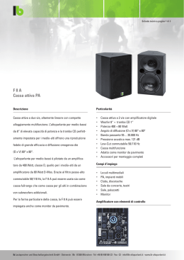
Digital Vertical Array
A.E.B. INDUSTRIALE s.r.l.
Via Brodolini, 8 - 40056 Crespellano (Bo) - ITALIA
Tel. + 39 051 969870 - Fax. + 39 051 969725
Internet: www.dbtechnologies.com
E-mail: [email protected]
MANUALE D’USO
USER MANUAL
BEDIENUNGSANLEITUNG
CARACTERISTIQUES TECHNIQUES
420120118 Rev. 9
2)
3)
Manuale d’uso
4)
5)
6)
7)
8)
9)
10)
11)
12)
INTERRUTTORE ALIMENTAZIONE
L’interruttore permette l’accensione e lo spegnimento del diffusore.
PORTA FUSIBILE “MAINS FUSE”
Alloggio per fusibile di rete.
PRESA DI ALIMENTAZIONE “MAINS INPUT”
Consente la connessione del cavo di alimentazione.
Il connettore utilizzato per il collegamento alla rete è un POWER CON® (blu)
PRESA DI ALIMENTAZIONE RILANCIO “MAINS OUTPUT LINK”
Consente di rilanciare l’alimentazione di rete. L’uscita è connessa in parallelo con
l’ingresso (3) e può essere utilizzata per alimentare un altro diffusore amplificato.
Il connettore utilizzato è un POWER CON® (grigio).
CONNETTORE DI INGRESSO " BALANCED INPUT”
Connettore XLRIngresso bilanciato a livello linea .
CONNETTORE DI USCITA "BALANCED LINK/OUT”
Il connettore “XLR” connesso in parallelo con l’ingresso (5) può essere utilizzato per
inviare il segnale audio in ingresso ad un altro diffusore amplificato.
CONTROLLO SENSIBILITA’ INGRESSO “INPUT SENS”
Questo controllo regola la sensibilità del segnale in ingresso all’amplificatore.
Tale controllo non influisce sul livello dell’uscita “BALANCED LINK/OUT”
INDICATORE LUMINOSO “LIMITER”
Questo indicatore s’illumina di colore rosso per indicare l'intervento del circuito
limitatore interno, il quale evita la distorsione dell'amplificatore e protegge gli
altoparlanti contro sovraccarichi.
INDICATORE LUMINOSO “SIGNAL”
Questo indicatore s'illumina di colore verde per indicare la presenza del segnale
audio (ad un livello di -20dB).
INDICATORE LUMINOSO “MUTE/PROT”
Questo indicatore di colore giallo indica lo stato dell’amplificatore. Nel normale
funzionamento il led è spento; nel caso in cui lampeggi o sia sempre acceso fare
riferimento alla tabella della diagnostica per la verifica dello stato dell’amplificatore.
INDICATORE LUMINOSO “READY”
Questo indicatore s'illumina di colore verde per indicare che la tensione di
alimentazione di rete è corretta. Nel normale funzionamento il led è acceso; nel
caso in cui lampeggi o sia spento fare riferimento alla tabella della diagnostica per la
verifica dello stato dell’amplificatore.
SELETTORE SETTAGGIO EQUALIZZAZIONE “SET-UP MODE”
Questo commutatore rotativo a 10 posizioni permette di selezionare la curva di
equalizzazione più adeguata al tipo di installazione.
Consultare la tabella per la corrispondenza delle curva di equalizzazione.
5
WARNING
HOT SURFACE
BALANCED
INPUT
T4
PUSH
6
Digital Vertical Array
BALANCED
LINK / OUT
7
ACTIVE P.F.C.
4
MAINS
LINK
"CAUTION"
+10dB
1
3
TO PREVENT ELECTRICAL SHOCK
DO NOT REMOVE COVER
TO PREVENT RISK OF FIRE
REPLACE FUSES WITH
SAME TYPE AND RATINGS
THIS APPARATUS MUST BE EARTHED
INPUT SENS
8
9
10
11
FULL RANGE MAINS INPUT
50-60Hz
85-265V
500W MAX
TECHNOLOGIES
1 = GND
2 = HOT
3 = COLD
"AVIS"
RISQUE DE CHOC ELECTRIQUE
NE PAS OUVRIR
POUR PREVENIR TOUT RISQUE DE FEU
REPLACER UN FUSIBLE
DE MÊME CARACTERISTIQUES
CET APPAREIL DOIT ÊNTRE RELIÉ A LA TERRE
+4dB
0dB
LIMITER
SIGNAL
SERIAL N.
READY
9
SET-UP
MODE
0
1
2
8
7
3
6
5
4
WARNING
HOT SURFACE
12
MAINS
FUSE
85-125V (T4A 250V)
200-250V (T2A 250V)
ON
MUTE/PROT
2
1
STATO DEL MODULO
LED ”READY”
(verde)
LED “MUTE/PROT” FUNZIONI
(giallo)
AUDIO
Accensione
Spento
Acceso per 5 sec.
Uso normale
Modifica equalizzazione
Acceso
Spento
Spento
Acceso per 5 sec.
Anomalia parziale
Acceso
Anomalia totale
Spento
Temperatura amplificatore:
superiore 70°C
Lampeggio lento
superiore 80°C
Lampeggio lento
Acceso fisso
Spento
Lampeggio veloce Spento
Caricamento dati
In mute per 5 sec.
Complete
Caricamento dati
In mute per 5 sec.
Parziale
In mute
Riduzione volume
in uscita a step
Riduzione volume
in uscita -15dB
Funzione “NOISE GATE”
Il NOISE GATE, o soppressore di rumore di fondo, riduce il soffio del diffusore in assenza
di segnale audio.
Il NOISE GATE interviene dopo qualche secondo di assenza di segnale audio , mettendo
in stato di MUTE l’amplificatore. Lo stato di MUTE è segnalato da un lampeggio veloce,
con cadenza lenta, del led giallo “MUTE/PROT”. Alla rilevazione del segnale audio, il
diffusore uscirà dallo stato di “MUTE” automaticamente.
Questa opzione può essere abilitata o disabilitata a seconda delle esigenze, mediante
una procedura da eseguire sul modulo amplificatore .
Manuale d’uso
Italiano
1)
Italiano
TABELLA DELLA DIAGNOSTICA
COMANDI E FUNZIONI
1) Verificare stato funzione “NOISE GATE”
Lo stato della funzione “ NOISE GATE” viene visualizzata dai led presenti sul pannello
amplififcatore durante l’accensione del modulo.
Funzione attiva = tutti i led accesi per 5-6 secondi
Funzione disattiva = solo il led giallo “MUTE/PROT” acceso per 5-6 secondi
2) Abilitazione/disabilitazione NOISE GATE
L’abilitazione e la disabilitazione del NOISE GATE avviene in maniera sequenziale ad
ogni spegnimento/accensione dell'amplificatore solo con selettore “SET-UP MODE” nella
posizione “9 “(service use only)
Per abilitare/disabilitare il NOISE GATE seguire la procedura:
Amplificatore spento
Selezionare posizione "9" del selettore “SET-UP MODE”
Accendere il modulo e controllare che:
*
Se il led rosso “LIMITER" rimane acceso fisso per qualche secondo
significa che la funzione NOISE GATE è stata disabilitata
*
Se il led rosso "LIMITER" lampeggia velocemente per qualche secondo
significa che la funzione NOISE GATE è stata abilitata
Attenzione!
Dopo l’abilitazione o la disabilitazione della funzione NOISE GATE, spegnere
l'amplificatore, selezionare con il selettore “SET-UP MODE” una posizione
(equalizzazione) che non sia la posizione"9" e riaccendere il sistema.
CLASSIFICAZIONE EMI
In accordo alle normative EN 55103, l'apparato è progettato e idoneo all'utilizzo in ambienti
Elettromagnetici E3 o inferiori (E2, E1).
2
Pressione sonora (SPL)
Componenti
Sensibilità ingresso nominale
Impedenza ingresso Bilanciato
Sbilanciato
Delay totale
Alimentazione
Forma diffusore
Dimensioni [LxHxP]
Peso
Attivo 3-Amps
Digitale - Classe T
420 W
840 W
80-19.000Hz
420 - 2500Hz
24dB/oct
128 peak
1 woofer 8” - bobina 64mm - neodimio
1 midrange 6,5” - bobina 38mm - neodimio
2 compression driver da 1” - neodimio
0 dBu
20Kohm
10Kohm
1,2mS
full-range con PFC
85-265V~ 50-60Hz
trapezioidale
580x330x240/160mm
13,2Kg
1)
2)
3)
4)
5)
6)
7)
8)
10)
160
240
9)
11)
580
330
12)
POWER SWITCH
This switch permits turning the speaker on and off.
"MAINS FUSE" FUSE CARRIER
Mains fuse housing.
"MAINS INPUT" POWER SOCKET
For connecting the power cable provided.
The connector used for mains connection is a POWER CON® (blue)
“MAINS OUTPUT LINK” RELAUNCH POWER SOCKET
For relaunching the mains power. The output is connected in parallel with input (3)
and can be used to power another amplified speaker.
The connector uses a POWER CON® (grey)
" BALANCED INPUT” INPUT CONNECTOR
Balanced input at line level. It is able to accept “XLR” sockets.
"BALANCED LINK/OUT ” OUTPUT CONNECTOR
The “XLR” connector connected in parallel with input (5) can be used to send the
input audio signal to another amplified speaker.
“INPUT SENS” INPUT SENSITIVITY CONTROL
This control regulates the sensitivity of the signal amplifier input.
This control does not affect the “BALANCED LINK/OUT” output level
“LIMITER” INDICATOR LIGHT
This indicator comes on red to indicate that the internal limiter circuit has tripped.
This prevents amplifier distortion and protects the speakers against overloads.
“SIGNAL” INDICATOR LIGHT
This indicator comes on green to indicate the presence of the audio signal (at a level
of -20dB).
“MUTE/PROT” INDICATOR LIGHT
This yellow indicator indicates amplifier status. In normal operating conditions, the
LED is off; if it flashes or is always on, refer to the diagnostics table to check amplifier
status.
“READY” INDICATOR LIGHT
This indicator comes on green to indicate that the main power voltage is correct. In
normal operating conditions, the LED is on; if it flashes or is off, refer to the
diagnostics table to check amplifier status.
“SET-UP MODE” EQUALIZATION SWITCH
This 10-position rotating switch permits selection of the equalization curve according
to installation type.
See table for corresponding equalization curve.
5
WARNING
HOT SURFACE
BALANCED
INPUT
T4
PUSH
6
Digital Vertical Array
BALANCED
LINK / OUT
7
ACTIVE P.F.C.
4
MAINS
LINK
"CAUTION"
+10dB
3
3
TO PREVENT ELECTRICAL SHOCK
DO NOT REMOVE COVER
TO PREVENT RISK OF FIRE
REPLACE FUSES WITH
SAME TYPE AND RATINGS
THIS APPARATUS MUST BE EARTHED
INPUT SENS
8
9
10
11
FULL RANGE MAINS INPUT
50-60Hz
85-265V
500W MAX
TECHNOLOGIES
1 = GND
2 = HOT
3 = COLD
"AVIS"
RISQUE DE CHOC ELECTRIQUE
NE PAS OUVRIR
POUR PREVENIR TOUT RISQUE DE FEU
REPLACER UN FUSIBLE
DE MÊME CARACTERISTIQUES
CET APPAREIL DOIT ÊNTRE RELIÉ A LA TERRE
+4dB
0dB
LIMITER
SIGNAL
SERIAL N.
READY
9
SET-UP
MODE
0
1
2
8
7
3
6
5
4
WARNING
HOT SURFACE
12
MAINS
FUSE
85-125V (T4A 250V)
200-250V (T2A 250V)
ON
MUTE/PROT
English
CONTROLS AND FUNCTIONS
Sistema
Tipologia amplificatore
Potenza RMS
Potenza musicale
Risposta in frequenza +/-3dB
Crossover
user manual
Manuale d’uso
Italiano
DATI TECNICI
2
1
4
Power ON
Off
On for 5 sec.
Normal use
Equalization changing
On
Off
Off
On for 5 sec.
Partial fault
Total fault
Amplifier temperature:
higher 70°C
On
Off
Slow flashing
On fixed
Slow flashing
Off
Fast flashing
Off
higher 80°C
Data loading
In mute for 5 sec.
Complete
Data loading
In mute for 5 sec.
Partial
In mute
Output volume
Reduction step
Output volume
reduction -15dB
“NOISE GATE” function
NOISE GATE, or residual noise suppressor, is a function to reduce noise of the speaker
without input audio signal applied.
NOISE GATE starts to work when there is no audio signal on input, after a few seconds, it
sets the amplifier section in MUTE state . MUTE state is indicated by slow flashing, of
“MUTE/PROT” yellow led. As soon as the audio signal passes he input section, the
speaker is set out of MUTE status automatically.
This option can be enabled and disabled according to the follow procedure on the
amplifier’s module.
1) How to check NOISE GATE status
The NOISE GATE status is visualized by the leds located on the amplifier panel during
switching on the module.
Function enabled =all leds flashes steady for 5-6 second.
Function disabled = only “MUTE/PROT” yellow led flasches steady for 5-6 second
2)
NOISE GATE enabled/disabled
NOISE GATE enabled/disabled can be done each time when switching ON and OFF the
amplifier module with “SET-UP MODE” selector on position “9 “(service use only).
To enable/disable NOISE GATE function follow this procedure:
Amplifier switched OFF
Set “SET-UP MODE” selector in position "9"
Switch ON the amplifier module and check following:
* if “LIMITER" red led steady flashes for a few seconds, the NOISE
GATE is enabled.
* if “LIMITER" red led flashes fast for a few seconds, the NOISE
GATE is disabled
System
Type of amplifier
RMS power
Musical power
Frequency responce +/-3dB
Crossover
Active 3-Amps
Digital - Class T
420 W
840 W
80-19.000Hz
420 - 2500Hz
24dB/oct
128 peak
1 woofer 8” - coil 64mm - neodymium
1 midrange 6,5” - coil 38mm - neodymium
2 compression driver da 1” - neodymium
0 dBu
20Kohm
10Kohm
1,2mS
full-range with PFC
85-265V~ 50-60Hz
trapezioid
580x330x240/160mm
13,2Kg
Sound pressure (SPL)
Component parts
Input sensitivity nominal
Impedence Bilanced
Unbalanced
Delay totale
Power supply
Speaker shape
Dimension [LxHxP]
Weight
user manual
LED “MUTE/PROT” AUDIO
(yellow)
FUNCTIONS
580
330
LED ”READY”
(green)
160
MODULE STATUS
English
TECHNICAL SPECIFICATION
240
user manual
English
DIAGNOSTICS TABLE
Warning!
After enabling or disabling the NOISE GATE function, switch off the amplifier, select
“SET-UP MODE” selector in any equalization position (except of "9" position) and
switch the system ON.
EMI CLASSIFICATION
According to the standards EN 55103 this equipment is designed and suitable to operate in E3
(or lower E2, E1) Electromagnetic environments.
5
6
2)
3)
Bedienungsanleitung
4)
5)
6)
7)
8)
9)
10)
11)
12)
NETZSCHALTER "POWER"
Dieser Schalter dient zum Ein- und Aus- Schalten der Lautsprecher
SICHERUNGSHALTER “MAINS FUSE”
Er enthält die Netzsicherung.
EINBAUSTECKER “MAINS INPUT”
Für den Anschluss des beiliegenden Netzkabels.
Für den Netzanschluss wird ein Stecker POWER CON® (blau) verwendet.
EINBAUKUPPLUNG FÜR DIE POWER-WEITERLEITUNG “MAINS OUTPUT
LINK”
Er dient zum Durchschleifen der Netzspannung. Der Ausgang ist parallel an den
Eingang (3) angeschlossen und kann zum Speisen eines weiteren verstärkten
Lautsprechers verwendet werden.
Der Steckverbinder ist eine Einbaukupplung POWER CON® (grau).
EINGANGSBUCHSE "BALANCED INPUT”
Symmetrischer XLR Eingang für Line-Pegel.
AUSGANGSBUCHSE "BALANCED LINK/OUT”
Der parallel zum Eingang (5) angeschlossene XLR-Anschluss kann dazu verwendet
werden, das ankommende Audiosignal an einen anderen verstärkten Lautsprecher
weiter zu leiten.
EMPFINDLICHKEITSREGLER EINGANG “INPUT SENS”
Dieser Regler dient zum Einstellen der Eingangs-Empfindlichkeit des Verstärkers .
Diese Regelung beeinflusst nicht den Ausgangspegel “BALANCED LINK/OUT”.
LED “LIMITER”
Diese rote LED leuchtet auf, um das Ansprechen der Limiterschaltung zu
signalisieren, die die Verzerrung des Verstärkers verhindert und die Lautsprecher
gegen Überlast schützt.
LED “SIGNAL”
Diese LED leuchtet grün, wenn das Audiosignal anliegt (mit einem Pegel von -20dB).
LED “MUTE/PROT”
Diese gelbe LED zeigt den Zustand des Verstärkers an. Während des normalen
Betriebs ist die LED ausgeschaltet; wenn sie blinkt oder ständig leuchtet, kann man
der Diagnosetabelle Informationen zur Kontrolle des Zustands des Verstärkers
entnehmen.
LED “READY”
Diese LED leuchtet grün, wenn das Gerät an die richtige Netzspannung
angeschlossen ist. Während des normalen Betriebs ist die LED eingeschaltet; wenn
sie blinkt oder ausgeschaltet ist, kann man der Diagnosetabelle Informationen zur
Kontrolle des Zustands des Verstärkers entnehmen.
“SET-UP MODE” EQUALIZATION SWITCH
An diesem 10-Positionen Drehknopf wird die Equalizer-Einstellung für die jeweilige
Installation eingestellt. (Siehe Equalisationstabelle)
5
WARNING
HOT SURFACE
BALANCED
INPUT
T4
PUSH
6
Digital Vertical Array
BALANCED
LINK / OUT
7
ACTIVE P.F.C.
4
MAINS
LINK
"CAUTION"
+10dB
7
3
TO PREVENT ELECTRICAL SHOCK
DO NOT REMOVE COVER
TO PREVENT RISK OF FIRE
REPLACE FUSES WITH
SAME TYPE AND RATINGS
THIS APPARATUS MUST BE EARTHED
INPUT SENS
8
9
10
11
FULL RANGE MAINS INPUT
50-60Hz
85-265V
500W MAX
TECHNOLOGIES
1 = GND
2 = HOT
3 = COLD
"AVIS"
RISQUE DE CHOC ELECTRIQUE
NE PAS OUVRIR
POUR PREVENIR TOUT RISQUE DE FEU
REPLACER UN FUSIBLE
DE MÊME CARACTERISTIQUES
CET APPAREIL DOIT ÊNTRE RELIÉ A LA TERRE
+4dB
0dB
LIMITER
SIGNAL
SERIAL N.
READY
9
SET-UP
MODE
0
1
2
8
7
3
6
5
4
WARNING
HOT SURFACE
12
MAINS
FUSE
85-125V (T4A 250V)
200-250V (T2A 250V)
ON
MUTE/PROT
2
1
ZUSTAND DES
MODULS
LED ”READY” LED “MUTE/PROT” AUDIO
(Grün)
(gelb)
FUNKTIONEN
Einschaltung
AUS
EIN für 5 sec.
Normalbetrieb
Wechsel Equalizer
Einstellung
Fehler Gesamtmenge
Fehler Parzial
Verstärkertemperatur :
zu hoch 70°C
EIN
AUS
AUS
EIN für 5 sec.
EIN
AUS
Langsames Blinken
EIN fixiert
Langsames Blinke
AUS
Schnelles Blinken
AUS
zu hoch 80°C
Progr a mm wird gela d en
Stummgeschaltet für 5 s.
Komplett
Programm wird geladen
Stummgeschaltet für 5 s
Parzial
Stummgeschaltet
Absenkung der LautStärke um Schritt
Absenkung der LautstStärke um -15dB
Funktion “NOISE GATE”
Das NOISE
GATE oder Rauschunterdrückung verringert das Rauschen des
Lautsprechers, wenn kein Tonsignal anliegt.
Das NOISE GATE schaltet sich nach einigen Sekunden ein, wenn kein Tonsignal anliegt,
und der Verstärker wird in die MUTE Stellung gesetzt. Der MUTE Zustand wird von einem
Blinken mit einer langsamen Frequenz der gelben LED “MUTE/PROT” signalisiert. Bei
der Erkennung des Tonsignals verlässt der Lautsprecher den MUTE Zustand
automatisch.
Diese Option kann man je nach den individuellen Bedürfnissen einschalten oder
ausschalten, indem man einer bestimmten Prozedur am Verstärkermodul folgt.
1) Den Zustand der Funktion “NOISE GATE” überprüfen
Der Zustand der Funktion “NOISE GATE” wird von den LEDs auf dem Bedienfeld des
Verstärkers angezeigt, während das Modul eingeschaltet wird.
Zustand “eingeschaltet” = alle LEDs sind an für 5-6 Sekunden
Zustand “ausgeschaltet” = nur die gelbe LED “MUTE/PROT” ist an für 5-6 Sekunden
2)
Bedienungsanleitung
Deutsch
1)
Deutsch
DIAGNOSETABELLE
BEDIENELEMENTE UND FUNKTIONEN
Einschalten/Ausschalten des NOISE GATES
Das NOISE GATE wird nach einer bestimmten Reihenfolge bei jedem
Ausschalten/Einschalten des Verstärkers ein- oder ausgeschaltet, und zwar durch den
Schalter “SET-UP MODE” in der Stellung “9” (service use only)
Um das NOISE GATE ein- oder auszuschalten der nachstehenden Prozedur folgen:
Ausgeschalteter Verstärker
Die Stellung “9” des Schalters “SET-UP MODE” wählen
Die Baugruppe einschalten und folgendes prüfen:
*
Wenn die rote LED “LIMITER” für einige Sekunden an bleibt
ohne zu blinken, heißt es, dass die Funktion NOISE GATE
ausgeschaltet wurde
*
Wenn die rote LED “LIMITER” schnell für einige Sekunden blinkt,
heißt es, dass die Funktion NOISE GATE eingeschaltet wurde.
Achtung!
Nach dem Ein- oder Ausschalten der Funktion NOISE GATE sollte man den
Verstärker ausschalten und mit dem Schalter “SET-UP MODE” eine beliebige
andere Stellung außer der Stellung “9” wählen (so wird das Ein- oder Ausschalten
des NOISE GATES umgangen) und das System wiederanschalten.
EMV Einstufung
Entsprechend der Norm EN 55103 ist diese Gerät entwickelt um inE3 (oder E2, E1)
elektromagnetischen Umgebungen zu arbeiten
8
Empfindlichkeit Eingang
Impedanz Eingang Symmetrisch
Ünsymmetrisch
Gesamtmenge verzögert
Netzspannung
Laufsprecherform
Abmessungen [LxHxT]
Gewicht
Aktive 3-Amps
Digital - Class T
420 W
840 W
80-19.000Hz
420 - 2500Hz
24dB/oct
128 peak
1 woofer 8” - coil 64mm -Neodym
1 midrange 6,5” - coil 38mm - Neodym
2 compression driver 1” - Neodym
0 dBu
20Kohm
10Kohm
1,2ms
full-range mit PFC
85-265V~ 50-60Hz
trapezförmig
580x330x240/160mm
13,2Kg
2)
3)
4)
5)
6)
7)
8)
9)
160
10)
580
11)
330
12)
INTERRUPTEUR GÉNÉRAL
L’interrupteur permet d’allmer et d’éteindre l’enceinte.
BLOC À FUSIBLE “MAINS FUSE”
Logement pour le fusible de réseau.
PRISE D'ALIMENTATION “MAINS INPUT”
Elle permet de connecter le cordon d'alimentation fourni.
Le connecteur utilisé pour le branchement au réseau est du type POWER CON®
(bleu)
PRISE D'ALIMENTATION RELANCE “MAINS OUTPUT LINK”
Elle permet de relancer l'alimentation de réseau. La sortie est branchée en parallèle
avec l'entrée (3) et peut être utilisée pour alimenter une autre enceinte amplifiée.
Le connecteur utilisé est du type POWER CON® (gris)
CONNECTEUR D'ENTRÉE “BALANCED INPUT”
Entrée symétrique au niveau ligne . Elle peut accueillir des prises “XLR”.
CONNECTEUR DE SORTIE “BALANCED LINK/OUT ”
Le connecteur “XLR” connecté en parallèle avec l'entrée (5) peut être utilisé pour
envoyer le signal audio en entrée d'une autre enceinte amplifiée.
CONTRÔLE SENSIBILITÉ ENTRÉE “INPUT SENS”
Ce contrôle règle la sensibilité du signal en entrée à l'amplificateur.
Ce contrôle n'influence pas le niveau de la sortie “BALANCED LINK/OUT”
INDICATEUR LUMINEUX “LIMITER”
Cet indicateur s'allume de couleur rouge pour indiquer l'intervention du circuit
limiteur interne qui évite la distorsion de l'amplificateur et protège les haut-parleurs
contre les surcharges
INDICATEUR LUMINEUX “SIGNAL”
Cet indicateur s'allume de couleur verte pour indiquer la présence du signal audio (à
un niveau de -20dB).
INDICATEUR LUMINEUX “MUTE/PROT”
Cet indicateur de couleur jaune indique l'état de l'amplificateur. Pendant le
fonctionnement normal, la LED est éteinte; si elle clignote ou si elle reste allumée
fixe, se référer au tableau de diagnostic pour contrôler l'état de l'amplificateur..
INDICATEUR LUMINEUX “READY”
Cet indicateur s'allume de couleur verte pour indiquer que la tension d'alimentation
de réseau est correcte. Pendant le fonctionnement normal, la LED est allumée; si
elle clignote ou si elle est éteinte, se référer au tableau de diagnostic pour contrôler
l'état de l'amplificateur.
SÉLECTER DE ÉGALISATION “SET-UP MODE”
Ce commutater rotatif à 10 positions permet de sélectionner courbe de égalisation.
(Consulter table pour la corrispondence des égalisation d’utilisation)
5
WARNING
HOT SURFACE
BALANCED
INPUT
T4
PUSH
6
Digital Vertical Array
BALANCED
LINK / OUT
7
ACTIVE P.F.C.
4
MAINS
LINK
"CAUTION"
+10dB
9
3
TO PREVENT ELECTRICAL SHOCK
DO NOT REMOVE COVER
TO PREVENT RISK OF FIRE
REPLACE FUSES WITH
SAME TYPE AND RATINGS
THIS APPARATUS MUST BE EARTHED
INPUT SENS
8
9
10
11
FULL RANGE MAINS INPUT
50-60Hz
85-265V
500W MAX
TECHNOLOGIES
1 = GND
2 = HOT
3 = COLD
"AVIS"
RISQUE DE CHOC ELECTRIQUE
NE PAS OUVRIR
POUR PREVENIR TOUT RISQUE DE FEU
REPLACER UN FUSIBLE
DE MÊME CARACTERISTIQUES
CET APPAREIL DOIT ÊNTRE RELIÉ A LA TERRE
+4dB
0dB
LIMITER
SIGNAL
SERIAL N.
READY
9
SET-UP
MODE
0
1
2
8
7
3
6
5
4
WARNING
HOT SURFACE
12
MAINS
FUSE
85-125V (T4A 250V)
200-250V (T2A 250V)
ON
MUTE/PROT
Caracteristiques techniques
Schalldruck (SPL)
Lautsprecher
240
Deutsch
Bedienungsanleitung
1)
System
Verstärker typ
RMS Leistung
Musikleistung
Frequezngang +/-3dB
Crossover
Français
COMMANDES ET FONCTIONS
TECHNISCHE EIGENSCHAFTEN
2
1
10
11
330
Caracteristiques techniques
160
240
Caracteristiques techniques
580
12
Français
Français
Configurazioni con DVAT4
Il flybar DRK10 è certificato per un massimo di 16 diffusori T4
Fare riferimento alla tabella 1 per determinare il peso complessivo sopportato dal flybar
con diffusori DVA T4 in diverse configurazioni
Tabella 1
Quantità
Peso
DVA T4
[kg]
[lbs.]
1
15
33
2
30
66
3
45
99
4
60
132
5
75
165
6
90
198
7
105
231
8
120
264
9
135
297
10
150
330
11
165
363
12
180
396
13
195
429
14
210
462
15
225
495
16
240
528
Modifiche strutturali al supporto flybar DRK10
Non possono essere eseguite modifiche senza il consenso del produttore.
Accessori originali dBTechnologies
Utilizzare solo parti originali dBTechnologies.
L’ente certificatore TÜV non ha omologato nessun altro accessorio per questo uso!
Installare sempre le parti in conformità con queste istruzioni di installazione!
Compilare e archiviare tutti i documenti del sistema DVA in un posto sicuro!
Attenzione
Nel caso in cui le suddette norme di sicurezza e il calcolo dei peso totale non siano
rispettate la dB Technologies non è responsabile di eventuali danni a cose e
persone!
Note
Durante le installazioni accertarsi che nella struttura portante del sistema vengano inclusi
nel calcolo dei pesi totali anche il peso del flybar DRK 10, delle catene dei sollevatori, dei
motori, dei cavi e ulteriori pesi aggiuntivi.
Normative di riferimento sull’uso e la manutenzione
La normativa “§ 39, VBG 9a” sull'assicurazione obbligatoria da parte datori di lavoro
Tedeschi per la prevenzione degli incidenti richiede che l'equipaggiamento del caricoportante debba essere ispezionato da personale qualificato ed i possibili difetti debbano
essere eliminati prima della consegna all’ utente finale.
La normativa “§ 41, VBG 9a” richiede che l'equipaggiamento del carico-portante debba
essere soggetto a una manutenzione non ordinaria successivamente a danni, riparazioni
e altri incidenti che possono avere effetto sulla capacità del carico-portante.
Attenzione
Le normative sulla sicurezza possono essere diverse in funzione del paese di
destinazione. Verificare le normative valide in accordo con il regolamenti sulle
sicurezze del paese!
Italiano
Il sistema DVA ha ottenuto la certificazione TÜV per la sospensione dei diffusori
DVA T4 e DVA S10dp tramite la staffa flybar DRK 10 .
Il rapporto certifica che il peso massimo applicabile al flybar DRK10 è di 250kg.
Manuale d’uso
Manuale d’uso
Italiano
INSTALLAZIONE
Configurazioni con DVA S10dp
Il flybar DRK10 è certificato per un massimo di 5 diffusori DVA S10dp (woofer Neodimio) e
4 diffusori DVA S10dp (woofer Ceramico)
Fare riferimento alla tabella 2 per determinare il peso complessivo sopportato dal flybar
con diffusori DVA S10dp in diverse configurazioni
Quantità
DVA S10dp
Peso
[kg] [lbs]
Peso
[kg] [lbs]
(Woofer Ceramico)
(Woofer Neodimio)
1
2
3
4
5
Quantità
DVA S10dp
48
96
144
192
240
106
212
317
423
528
1
2
3
4
54
108
162
216
119
238
357
476
Tabella 2
Configurazioni con miste con DVA T4 e DVA S10dp (woofer Neodimino)
La modularità del sistema DVA permette configurazioni sospese miste tra diffusori
DVA T4 e DVA S10dp. E’ necessario considerare che un subwoofer DVA S10dp appeso
corrisponde, in termini di peso, a circa 4 diffusori DVA T4.
Per questo motivo è necessario calcolare il carico totale nelle diverse combinazioni.
Esempio:
13
Quantità
8
2
Peso x qtà
120Kg
96Kg
Peso configurazione
DVA T4
DVA S10dp(woofer Neodimio)
Quantità
12
1
Peso x qtà
180Kg
48Kg
Peso configurazione
DVA T4
DVA S10dp(woofer Neodimio)
216Kg
228Kg
DVA Composer - Simulazione acustica di sistemi serie DVA
DVA Composer è un software di puntamento e simulazione acustica per tutti i modelli
Line Array della serie DVA e relativi Subwoofers.
Tale software permette di gestire un sistema stereo composto da line array e subs,
simulando separatamente la risposta acustica di entrambi.
Vengono inoltre fornite all'utente una serie di informazioni quali allineamento in fase
tra i sistemi sospesi e i relativi subwoofer a terra e vengono suggeriti angoli ottimali tra
i moduli line array e relativi preset di equalizzazione, al fine di ottimizzare le
performance del sistema anche per utenti non esperti.
Si raccomanda di scaricare gratuitamente il software DVA_Composer
direttamente dal sito dB Technologies (www.dbtechnologies.com) nella
sezione dedicata «Software & Controller»
DOWNLOAD
14
DVA T4 configuration
The DRK 10 flybar attests that the maximum number of DVA T4 is 16.
Refer to table 1 to determine the total weight borne by flybar according to the different
DVA T4 configurations.
Table 1
Quantity
Weight
DVA T4
[kg]
[lbs.]
1
15
33
2
30
66
3
45
99
4
60
132
5
75
165
6
90
198
7
105
231
8
120
264
9
135
297
10
150
330
11
165
363
12
180
396
13
195
429
14
210
462
15
225
495
16
240
528
Structural modification of DRK 10 flybar
No structural modifications may be made without the manufacturer's consent.
Use only dB Technologies original parts
Original parts dB Technologies
Use only dB Technologies original parts.
The TÜV authorizing body has not certificated any other parts for use!
Always install parts in accordance with these installation instruction!
Compile and store all DVA system documents in a safe place!
Warning
If the security norms and total weight calculations are not observed, dB Technologies
is not responsible for any possible damage to people and things.
Note
During installation ensure that carrying structure of the system has added in the total
weight also the DRK 10 flybar weight, chain hoists, motors, cables and further weights.
Initiation and Operation
The safety regulation “§ 39, VBG 9a” of the German employers' liability insurance
association's accident prevention regulations requires that load-carrying equipment be
inspected by a qualified expert and possible defects be eliminated prior to initial
commissioning by the recipient.
The safety regulation “§ 41, VBG 9a” requires that load-carrying equipment be subjected
to a non-routine inspection following damage, repair work and other incidents that can
affect load-carrying capacity.
Warning
The safety regulations might be different in other countries. Please check with your
national safety authority the valid regulations!
English
DVA system has obtained the TÜV certification for suspension of DVA T4 and DVA
S10dp speakers through flybar stirrup DRK 10.
The report certifies that the maximum weight applying to DRK 10 flybar is 250Kg.
user manual
user manual
English
INSTALLATION
DVA S10dp configuration
The DRK 10 flybar attests that the maximum number of DVA S10dp with Neodymium
woofer is 4 and DVA S10dp with Ceramic woofer is 5.
Refer to table 2 to determine the total weight borne by flybar according to the different
DVA S10dp configurations.
Quantity
DVA S10dp
Weight
[kg] [lbs]
(Neodymium woofer)
1
2
3
4
5
Quantità
DVA S10dp
Weight
[kg] [lbs]
(Ceramic woofer)
48
96
144
192
240
106
212
317
423
528
1
2
3
4
54
108
162
216
119
238
357
476
Table 2
Mixed configuration with DVA T4 and DVA S10dp (Neodimium woofer)
The modular structure of DVA system permits mixed suspension configuration between
DVA T4 and DVA S10dp. It is necessary to consider that one DVA S10dp hanging
subwoofer corresponds, in weight terms, to about four DVA T4 speakers.
For this reason it is necessary to calculate the total weight according to the different
configurations.
Examples:
15
DVA T4
DVA S10dp(Neodimium woofer)
Quantity
8
2
Weight x qty
120Kg
96Kg
DVA T4
DVA S10dp(Neodymium woofer)
Quantity
12
1
Weight x qty
180Kg
48Kg
Configuration weight
216Kg
Configuration weight
228Kg
DVA Composer Acoustical Simulation and aiming for DVA Systems
DVA Composer is a 2D software for aiming and simulating acoustical response of all line
arrays and Subwoofers from DVA Series.
The software allows you to set up a stereo system composed by tops and subs, and
simulates separately the acoustical response of both.
DVA Composer also gives to the user all the information about phase alignment between
flown systems and ground stacked subwoofers, as well as it suggests an optimized
aiming of the line arrays modules and their suggested EQ presets, in order to guarantee
maximum performances even for non-expert customers.
It is recommended to download DVA_Composer free software directly from
dB Technologies (www.dbtechnologies.com) in the special section «Software
& Controller»
DOWNLOAD
16
DVA T4 Konfiguration
Es dürfen maximal 16 T4 Topteile an einem DRK 10 Flugrahmen befestigt werden.
Entsprechend Tabelle 1 bestimmen sie das Gesamtgewicht und Belastung des DRK 10
Flugrahmens verschiedener DVA T4 Konfigurationen
Tabelle 1
Anzahl
Gewicht
DVA T4
[kg]
[lbs.]
1
15
33
2
30
66
3
45
99
4
60
132
5
75
165
6
90
198
7
105
231
8
120
264
9
135
297
10
150
330
11
165
363
12
180
396
13
195
429
14
210
462
15
225
495
16
240
528
DVA S10dp Konfigurationen
Es dürfen maximal 5 S10dp Subwoofer mit Neodimium woofer order es dürfen maximal 4
S10dp Subwooferan mit Ceramic woofer einem DRK 10 Flugrahmen befestigt werden.
Entsprechend Tabelle 2 bestimmen sie das Gesamtgewicht und Belastung des DRK 10
Flugrahmens verschiedener DVA S10dp Konfigurationen
Anzahl
DVA S10dp
Anzanhl
DVA S10dp
Gewicht
[kg] [lbs]
(Neodymium woofer)
1
2
3
4
5
Gewicht
[kg] [lbs]
(Ceramic woofer)
48
96
144
192
240
106
212
317
423
528
1
2
3
4
54
108
162
216
119
238
357
476
Tabelle 2
Gemischte Konfigurationen mit DVA T4 und DVA S10dp
Die mechanische Konstruktion des DVA Systems erlaubt eine gemischte Konfiguration
zwischen DVA T4 und DVA S10dp. Es ist wichtig zu beachten, dass ein geflogener DVA
S10dp Subwoofer dem Gewicht von vier über DVA T4 entspricht. Aus diesem Grund ist es
notwendig, das Gesamtgewicht entsprechend der unterschiedlichen Konfigurationen zu
bestimmen.
Beispiele:
17
Veränderungen an dem DRK 10 Flugrahmen
Es dürfen ohne zustimmung des Herstellers keine bauartlichen Veränderungen
vorgenommen werden.
Versenden Sie ausschließliche dBTechnologies Originalteile.
Original dB Technologies Teile
Es sind keine anderen Teile seitens des TÜV zugelassen!
Die Montage muss gemäß dieser Installations- Anleitung vorgenommen werden!
Verwahren Sie alle Dokumente des DVA Systems an einen sicheren Ort!
Warnung
Werden die Sicherheitsvorschriften und die maximal zulässigen Gewichte nicht
beachtet, ist dB Technologies nicht verantwortlich für irgendwelche Schäden an
Personen oder Sachen.
Hinweis
Stellen Sie zur Installation sicher, dass die Tragevorrichtung für das Systems auch die
Gewichte des DRK 10 Flugrahmens, des Motors, des Kettenzuges, der Kabel und
anderer Gewichte tragen kann.
Inbetriebnahme und Betrieb
Nach § 39 VBG 9a müssen Lastaufnahmeeinrichtungen vor der ersten Inbetriebnahme
beim Empfänger durch einen Sachkundigen geprüft und etwaige Mängel behoben
werden.
Nach § 41 VBG 9a müssen Lastaufnahmeeinrichtungen nach Schadensfällen oder
anderen Vorkommnissen, welche die Tragfähigkeit beeinflussen können, und nach
Instandsetzungsarbeiten einer außerordentlichen Prüfung unterzogen werden.
Warnung
Sicherheits-Vorschriften kann sich je nach dem Bestimmungsland. Überprüfen
Sie die geltenden Vorschriften in Einklang mit den Vorschriften über die
Sicherheit in dem Land!
Deutsch
Das DVA System erhielt die TÜV- Prüfung für DVA T4 und S10dp Lautsprecher in
Kombination mit DRK 10 Flugrahmen.
Entsprechend der Prüfung beträgt das maximal zulässige Gewicht 250 kg.
Bedienungsanleitung
Bedienungsanleitung
Deutsch
INSTALLATION
DVA T4
DVA S10dp(Neodimium woofer)
Anzahl
8
2
Gewicht x Anzahl
120Kg
96Kg
DVA T4
DVA S10dp(Neodymium woofer)
Anzahl
12
1
Gewicht x Anzahl
180Kg
48Kg
Konfigurationen Gewicht
216Kg
Konfigurationen Gewicht
228Kg
DVA Composer Akustiksimulation für Systeme der Serie DVA
DVA Composer ist eine Software zur Beschallungsplanung und simulation für alle Line
Array-Modelle der Serie DVA und den zugehörigen Subwoofern.
Sie ermöglicht die Verwaltung eines Stereosystems, das aus Line Arrays und Subwoofern
besteht, wobei das akustische Ansprechprofil jeweils separat simuliert wird.
Dem Nutzer werden eine Reihe von Daten geliefert, z.B. die Phasenanpassung zwischen
den Hängesystemen und den entsprechenden Subwoofern am Boden. Außerdem
werden die optimalen Winkel zwischen den Line Array-Modulen und den entsprechenden
Equalizer-Presets angegeben, so dass auch weniger erfahrene Benutzer die Leistungen
des Systems optimieren können.
Wir empfehlen, die Software DVA_Composer direkt von der Webseite dB
Technologies (www.dbtechnologies.com) im Abschnitt «software &
Controller» herunterzuladen
DOWNLOAD
18
Configurations avec DVAT4
Le flybar DRK10 est certifié pour un maximum de 16 diffuseurs T4
Consulter le tableau 1 afin de déterminer le poids compressif supporté par le flybar avec
diffuseurs DVA T4 dans différentes configurations.
Tableau 1
Quantité
Poids
DVA T4
[kg]
[lbs.]
1
15
33
2
30
66
3
45
99
4
60
132
5
75
165
6
90
198
7
105
231
8
120
264
9
135
297
10
150
330
11
165
363
12
180
396
13
195
429
14
210
462
15
225
495
16
240
528
Configurations avec DVA S10dp
Le flybar DRK10 est certifié pour un maximum de 5 diffuseurs DVA S10dp avec
Neodymium woofer ou pour un maximum de 4 diffuseurs DVA S10dp avec Ceramic
woofer. Consulter le tableau 2 afin de déterminer le poids compressif supporté par le
flybar avec diffuseurs DVA S10dp dans différentes configurations.
Quantité
DVA S10dp
Poids
[kg] [lbs]
Quantité
DVA S10dp
(Ceramic woofer)
(Neodymium woofer)
1
2
3
4
5
Poids
[kg] [lbs]
48
96
144
192
240
106
212
317
423
528
1
2
3
4
54
108
162
216
119
238
357
476
Tableau 2
Configurations avec mélange DVA T4 et DVA S10dp (Neodimium woofer)
La modularité du système DVA permet des configurations suspendues mixtes entre les
diffuseurs DVA T4 et DVA S10dp. Il est nécessaire de considérer qu'un subwoofer DVA
S10dp suspendu correspond, en terme de poids, plus ou moins à 4 diffuseurs DVA T4.
C'est pour ce motif qu'il est nécessaire de calculer la charge totale dans les différentes
combinaisons.
Exemple:
19
Modifications de structure sur le support flybar DRK10
Aucune modification ne peut être faite sans l'accord du producteur.
Accessoires originaux dBTechnologies
N'utiliser exclusivement que des pièces originales dBTechnologies.
L'organisme de certification TÜV n'a homologué aucun autre accessoire prévu pour cet
effet!
Installer toujours les parties en conformité avec ces instructions d'installation!
Remplir et mettre aux archives tous les documents du système DVA dans un lieu sûr !
Attention
Dans le cas où lesdites mesures de sécurité et de calcul de poids total ne sont pas
respectées, dB Technologies n'est en aucun cas responsable des éventuels
dommages provoqués aux objets et aux personnes!
Notes
Durant les installations, bien s'assurer que dans la structure portante du système soient
inclus dans le calcul des poids totaux ainsi que le poids du flybar DRK 10, des chaînes des
élévateurs, des moteurs, des câbles et autres poids ajoutés.
Début et fonctionnement
La norme sur la sécurité “§ 39, VBG 9a” sur l'assurance obligatoire de la part des
employeurs allemands pour la prévention des accidents demande que l'équipement du
porte-charge doit être inspecté par un personnel qualifié et que les possibles défauts
doivent être éliminés avant la livraison à l'usager final.
La norme sur la sécurité “§ 41, VBG 9a” demande que l'équipement du porte-charge doit
être sujet à une manutention non ordinaire suite à des dommages, réparations et autres
incidents qui peuvent avoir effet sur la capacité du porte charge.
Attention
Les normes sur la sécurité peuvent être différentes en fonction du pays de
destination. Vérifier les normes en rigueur en accord avec les règlements sur les
sécurités du pays!
Français
Le système DVA a obtenu la certification TÜV pour la suspension des diffuseurs
DVA T4 et DVA S10dp grâce à l'étrier flybar DRK 10 .
Le rapport certifie que le poids maximum applicable au flybar DRK10 est de 250kg.
Caracteristiques techniques
Caracteristiques techniques
Français
INSTALLATION
Quantité
8
2
Poids par quantité
120Kg
96Kg
Poids configuration
DVA T4
DVA S10dp(Neodimium woofer)
Quantité
12
1
Poids par quantité
180Kg
48Kg
Poids configuration
DVA T4
DVA S10dp(Neodymium woofer)
216Kg
228Kg
DVA Composer Simulation acoustique de systèmes de séries DVA
DVA Composer est un logiciel de direction et simulation acoustique pour tous les
modèles de lignes de source de la série DVA et les caissons de basse relatifs.
Ce logiciel permet de gérer un système stéréo composé de ligne source et de
caissons de basse, simulant séparément la réponse acoustique de chacun des deux.
De plus, de nombreuses informations sont fournies à l'utilisateur, comme l'alignement
en phase entre les systèmes suspendus et les relatifs caissons de basse à terre, ou la
syggestion d'angles optimisés entre les modules de ligne de source et les préréglages
d'égaliseur relatifs. Cela permet d'optimiser les performances du système, même pour
des utilisateurs non experts.
On conseille de télécharger gratuitement le logiciel DVA_Composer
directement à partir du site dB Technologies (www.dbtechnologies.com)
dans la section dédiée « Software & Controller »
DOWNLOAD
20
CONFIGURATION SYSTEM
SET-UP EXAMPLES
DVA T4 PRESET EQUALIZATIONS
STRAIGHT from 0° to 2,5°
FROM 6 TO 8
CURVED
from 5° to 15°
STRAIGHT from 0° to 2,5°
1
2
3
6
MID
CURVED
from 5° to 7,5°
7
CURVED
from 10° to 15°
N°OF BOXES:
6
8
Set-up 4
set-up 6
set-up 7
set-up 7
set-up 5
set-up 5
MID CURVED
from 5° to 7,5°
FRONT FIELD
2
CURVED
from 5° to 15°
set-up 1
set-up 7
set-up 8
set-up 1
CURVED
from 10° to 15°
CONFIGURATION :
N°OF BOX:
CURVED
from 5° to 15°
STRAIGHT
from 0° to 2,5°
21
set-up 0
set-up 6
9
set-up 5
FRONT FIELD
2
8
set-up 6
set-up 4
set-up 4
CONFIGURATION :
N°OF BOX:
set-up 3
5
STRAIGHT from 0° to 2,5°
SERVICE USE ONLY
set-up 2
4
STRAIGHT
from 0° to 2,5°
FROM 9 TO 12
from 5° to 15°
set-up 1
set-up 2
set-up 3
N°OF BOXES:
CURVED
set-up 1
STRAIGHT
from 0° to 2,5°
from 5° to 15°
4
CURVED
from 5° to 15°
FROM 3 TO 5
CURVED
0
STRAIGHT
from 0° to 2,5°
STRAIGHT from 0° to 2,5°
N°OF BOXES:
2
CURVED
from 5° to 15°
ANGLES
E
SHAPE
N°OF BOXES:
EQU
SET
RAG
COVE
FROM 1 TO 2
NUMBER
OF BOXES
set-up 8
22
DRK 10 accessorio
Accessory DRK 10
Appeso
Hanging on
In appoggio
Groundstack
Appeso
Hanging on
INSTALLAZIONE
INSTALLATIONEN
Phase 5
Phase 6
INSTALLATION
INSTALLATIONS
Phase 7
Phase 8
Phase 1
Phase 2
INCLINAZIONE INCLINATION
NEIGUNG INCLINAISON
SERIES
5°
5°
7,,5
10°
°
12,5
15 °
Phase 3
23
Phase 4
24
In appoggio
Groundstack
INSTALLAZIONE
INSTALLATIONEN
Phase 1
INSTALLATION
INSTALLATIONS
Phase 2
Phase 7
Phase 8
INCLINAZIONE INCLINATION
NEIGUNG INCLINAISON
SERIES
5°
7,5°
10°
Phase 3
Phase 4
5°
12 ,
15°
5°
5°
2,5°
2,5°
0°
-2,5°
0°
-2,5°
-5°
-5°
-7,5°
-7,5°
GROUND STACKED
USE ONLY
Phase 5
25
Phase 6
26
DVA T4 + DVA S10
Utilizzo in appoggio verticale (DVA T4 montaggio “Ground stacking”)
Supported use (DVA T4 ““Ground stacking” assembling)
27
DVA T4 + DVA S20
Utilizzo in appoggio verticale (DVA T4 montaggio “Ground stacking”)
Supported use (DVA T4 ““Ground stacking” assembling)
28
Opzione DSA 4
DSA 4 Option
Per supporto asta
Stand adaptor
In appoggio
Floor stack
Per supporto asta
Stand adaptor
Solo con DVA S10
Only with DVA S10
In appoggio
Floor stack
29
30
ISTRUZIONI DI SICUREZZA PER ACCESSORI / SAFETY INSTRUCTIONS FOR ACCESSORIES
ZUBEHÖR SICHERHEITSHINWEISE / INSTRUCTIONS DE SÉCURITÉ POUR LES ACCESSOIRES
Quando viene utilizzato un carrello, usare cautela durante lo spostamento dell’apparecchio per evitare infortuni a
causa di capovolgimenti.
When a cart is used, use caution when moving the cart-apparatus combination to avoid injury from tip-over.
Beim Verfahren des Geräts auf einem Wagen darauf achten, dass es nicht zu Unfällen kommt, weil das Gerät
umkippt.
Quand on utilise un chariot, déplacer l'appareil avec précaution afin d'éviter des accidents à cause de
renversements.
Carello - opzione DT 6
Trolley - DT 6 option
Flightcase per 4 DVA T4 - opzione DF 4
Flightcase for 4 DVA T4 - DF 4 option
Flybar
Carello
Trolley
31
Opzione DTF 4
DTF 4 Option
DTF 4 = DT 6 + DF 4
32
Staffa a muro - opzione DWB 3
Wall bracket - DWB 3 option
Gli accessori per il fissaggio della staffa
non sono forniti in dotazione
The fixing accessory for wall bracket are
not suppling with the kit
Fissaggio su strutture a traliccio
Fixing on truss structures
Fissaggio a muro con staffe
Wall brackets fixing
Protezione pioggia - opzione DSA 4
Stand adaptor - DSA 4 option
Fissaggio a muro con staffa e catene
Wall bracket and chains fixing
33
34
POWER
FILTER
POWER
FILTER
DIGITAL SUPPLY
ANALOG SUPPLY
SMPS
PFC
Switching Mode
Power Supply
EEPROM
MAINS
FUSE
Power Factor
Correction
Power Supply Unit
PSU CONTROL
CONTROL DATA
CONTROL DATA
LIMITER
SIGNAL
READY
MUTE
PROT
MAINS LINK
N
L
POWER
SWITCH
BALANCED
LINK/OUTPUT
FULL RANGE
MAINS INPUT
Contact dBTechnologies pour les accessoires à utiliser avec la machine.
N'accepterons pas toutes les responsabilités lorsque des accessoires inappropriés ou ne conviennent pas à des
dispositifs supplémentaires sont utilisés.
MicroController Unit
TEMP
SENSOR
SET-UP
MODE
INPUT
SENS
35
BALANCED
INPUT
Contattare dB Technologies per gli accessori da utilizzare a corredo.
Si declina ogni responsabilità da un utilizzo inappropriato degli accessori o di dispositivi aggiuntivi non idonei allo
scopo.
Kontaktieren sie dBTechnologies für passendes Lautsprecherzubehör.
Falls unpassendes Zubehör verwendet wird, wird jegliche Haftung ausgeschlossen.
MCU
DAC
DAC
DAC
Digital Signal
Processor
HARDWARE
LIMITER
ADC
24Bit
AUDIO SENS
ISTRUZIONI DI SICUREZZA PER ACCESSORI / SAFETY INSTRUCTIONS FOR ACCESSORIES
ZUBEHÖR SICHERHEITSHINWEISE / INSTRUCTIONS DE SÉCURITÉ POUR LES ACCESSOIRES
Contact dB Technologies for accessories to be used with speakers.
Will not accept any responsibilty when inappropriate accessories or not suitable additional devices are used.
POWER STAGE SUPPLY
Class T
POWER
FILTER
WOOFER 8”
MIDRANGE 6,5”
COMPRESSION
DRIVER 1”
DSP
ADC CONTROL DATA
Analogic Digital
Converter
DSPCONTROL DATA
Digital Analogic
Converter
ANALOG
FILTER
Class T
Nota:
Utilizzare il sollevatore solo con l’accessorio
DRK 10 (flybar)
Note:
To use the lift of speaker only with DRK 10
accessory (flybar)
POWER
FILTER
Sollevatore per diffusori - opzione DRL 45
Lift for speakers - DRL 45 option
COMPRESSION
DRIVER 1”
SCHEMA A BLOCCHI
BLOCK DIAGRAM
BLOCKSCHALTBILD
DIAGRAMA EM BLOQUES
36
Scaricare