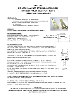
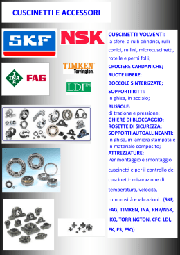
Manuale Di Uso e Manutenzione
Owner’s manual
Italiano
English
!
"
#
$
%
& '
(
) '
*
+,
+,
- .
/
www.frmbike.com
Distributed by:
THE BIKE SHOP
Via Mattei 18/a 48025 Riolo Terme ITALY
Phone +39 0546 70310 fax 74623e-mail : [email protected]
Pagina 1
ITALIANO
Corsa alla ruota 100 mm
Congratulazioni per aver scelto la FRM 12HP.
La 12HP è una MTB estremamente sofisticata che richiede cura ed attenzione.
E’ assolutamente necessario leggere questo manuale prima di montare o usare la bici.
Il telaio 12HP è costruito utilizzando
tubazioni Easton Ultralite MTB in
alluminio 7005 a doppio e triplo spessore
sia per il triangolo principale che per il
carro posteriore.
Molte delle parti della sospensione sono
ricavate dal pieno con macchine a
controllo numerico (CNC), cosa che
permette una riduzione dei pesi ed una
precisione ineguagliabile della
costruzione
Il fulcro principale, così come quelli del
bilanciere, ruota su cuscinetti di
precisione a rulli, per una assenza totale
di giochi ed una durata nel tempo
illimitata.
Il 12HP può essere considerata una Trial
Bike per uso Granfondo ed escursionismo
Il peso è di circa 2,4 kg incluso di
ammortizzatore.
Struttura della sospensione
La sospensione 12HP è del tipo Fuor-Bar
con Swing-Link e giunto Horst.
Questo tipo di sospensione offre grande
rigidità laterale, in quanto sia il forcellone
che i foderi verticali contribuiscono a
combattere le flessioni laterali.
L’ammortizzatore, separato dalla
sospensione per mezzo del bilanciere
(swing-link), non viene sollecitato da forze
laterali che ne comprometterebbero il
buon funzionamento.
Posizione del fulcro
La sospensione non viene compressa o
estesa dalla forza impressa sui pedali, ma
non ne viene neppure bloccata.
Questo è il sistema più efficiente per
progettare sospensioni da bici, perchè la
forza della pedalata non muove la
sospensione, ma viene solamente
utilizzata per fare avanzare la bici.
La pedalata è fluida e non influenzata dal
movimento della sospensione, perchè
questa è completamente attiva.
Ciò significa che la sospensione è libera di
comprimersi ed estendersi in ogni
condizione.
L‘influenza della frenata è completamente
eliminata con l’uso dei Giunti Horst tra
foderi orizzontali e verticali.
Il giunto Horst è tale solo se la ruota e
l’impianto frenante sono parte dei foderi
verticali.
Questa configurazione impedisce al freno di
ruotare rispetto alla ruota, cosi che i foderi
verticali rimangono ad una angolo costante
rispetto al telaio, nel momento in cui la
sospensione si comprime.
Il Pedal-Feedback o il Brake-Induced
Feedback sono eliminati per mezzo di un
accurato posizionamento dei punti di
infulcro, in modo che il movimento della
ruota sia praticamente verticale.
La distanza tra movimento centrale e ruota
posteriore rimane praticamente invariata
durante la compressione della sospensione.
Il baricentro della sospensione si trova nella
posizione che influenza in maniera minore
la attività della sospensione, permettendole
di essere attiva anche mentre si pedala e
di non venire influenzata dalla forza della
pedalata.
Un leveraggio regressivo compensa le
naturale progressività degli ammortizzatori
ad aria
Tutte le parti della sospensione sono
ricavate in CNC da blocchi di alluminio
Tutti i punti di snodo ruotano su cuscinetti a
rulli
Telaio progettato da Franco Ricci Mingani e
costruito completamente in Italia
Finitura
Telaio e sospensione sono micropallinati a
sfere di vetro per una migliore resistenza a
fatica ed anodizzati per una ottima
resistenza agli agenti atmosferici e agli urti.
LA SOSPENSIONE E’ ASIMMETRICA
La parte in CNC che collega il fulcro
primario della sospensione ai foderi
orizzontali è ora composta da due parti
saldate in posizione per mezzo di un
tubino centrale, posizionato obliquamente
rispetto ad esse.
Questo perché il pezzo che forma il
passaggio ruota destro deve arcuarsi
verso il basso per far posto al deragliatore
ed alla catena, mentre la parte sinistra
prosegue rettilinea verso il giunto Horst.
Il peso del telaio si è ridotto di 60 gr
rispetto alla sospensione simmetrica e la
rigidità è aumentata.
I forcellini posteriori sono ora dotati di
nervature di irrigidimento che li rendono
meno soggetti a rotture
LA POSIZIONE DELLA SELLA
Lo scostamento della sella rispetto al
movimento centrale e la sua
inclinazione, variano a seconda che la
sospensione sia scarica o sia
compressa dal vostro peso. Dopo
averla tarata, salire in sella e bloccare
la sospensione in posizione con un
cuneo di legno inserito tra il bilanciere
ed il tubo piantone. Solo a questo
punto è possibile misurare lo
scostamento della sella con un filo a
piombo e la sua inclinazione con la
livella.
I telai 12HP sono utilizzabili esclusivamente per il Cross Country.
Qualsiasi altro uso improprio limita la responsabilità del costruttore.
Forcelle a doppia piastra sono sconsigliate e limitano la garanzia del telaio.
Per ottenere le migliori prestazioni, il
telaio 12HP deve essere assemblato con
componenti idonei. Si raccomanda di
seguire le seguenti istruzioni.
FORCELLA:
Il tubo di sterzo accetta sterzi da
1 1/8”. La corsa consigliata va da 80 a 100
mm. Non montare forcelle a doppia piastra.
MOVIMENTO CENTRALE:
la scatola movimento è da 68 mm a passo
inglese.
CORONE GUARNITURA:
per il più corretto funzionamento della
sospensione utilizzare corone di tipo
Compact e controllare che la linea catena sia
tra 47,5 e 50 mm (misurata dalla corona
centrale all’asse di simmetria del telaio)
DERAGLIATORE:
utilizzare deragliatori di tipo Top-Pull con
fascetta di diametro 31,8. I deragliatori
Shimano di tipo Top Swing (fascetta bassa)
non possono essere montati sulla Be Active.
Sono compatibili invece deragliatori Shimano
Down Swing (tradizionali con fascetta alta),
oppure SRAM X-Gen. Utilizzare sempre un
tubino di teflon entro il tubetto metallico
saldato sul telaio.
CAMBIO :
la guaina del cambio parte dal comando
cambio destro e prosegue ininterrotta fino al
cambio, stretta dai due farfallini sul tubo
obliquo e passando poi all’interno del fodero
destro
FRENI :
Il 12HP è compatibile sia per freni V-Brake
che per freni a disco Nel caso dei freni V-
Brake è necessario ordinare gli appositi
collarini smontabili che vengono posizionati
sui foderi verticali.
REGGISELLA :
il diametro del reggisella è di 27,2 mm. Fare
in modo che almeno 60 mm di reggisella
rimangano all’interno del telaio.
MANUTENZIONE
Non lavare mai la bici con prodotti o solventi
derivati dal petrolio (benzina, petrolio, nafta
ecc) che sciolgono il grasso dei mozzi,
movimento centrale e sterzo, ma solo con
detergenti o saponi ad acqua. Dopo il
lavaggio, asciugare e ungere catena, pedali,
movimento e deragliatori con oli specifici.
Suggeriamo vivamente l’uso dei prodotti di
manutenzione Morgan Blue / FRM: Olio per
catena Extra Dry, Grasso per cuscinetti e
sgrassante Bio Cleaner
Pagina 2
ITALIANO
MANUTENZIONE
1
2
l telaio 12HP richiede una manutenzione
non molto diversa da quella riservata ad
ogni altro telaio da MTB.
La sospensione infatti non richiede cure
particolari se non un semplice ingrassaggio
dei cuscinetti sui quali scorre la
sospensione. Telaio e sospensione sono
anodizzati per cui non richiedono alcun tipo
di manutenzione, se non una normale
pulizia.
3
4
5
6
7
8
Prima di ogni uscita
Controllare la forcella anteriore.
Controllare serraggio attacco e
manubrio.
Controllare gioco sterzo.
Controllare tensione sganci rapidi.
Controllare funzionamento freni e
usura pattini.
Controllare cambio e deragliatore.
Controllare pressione gomme.
Controllate centratura ruote
1
2
3
4
5
Ogni 3-6 mesi
Sostituire l’olio della forcella
Smontare, pulire e ingrassare lo sterzo
ed il movimento centrale
Smontare, pulire ed ingrassare i mozzi.
Sostituire guaine e cavi del cambio,
deragliatore e freni.
Smontare, pulire ed ingrassare gli snodi
della sospensione.
COME SMONTARE LA SOSPENSIONE
ATREZZATURA NECESSARIA:
• 2 chiavi a brugola da 4 mm
• 2 chiavi a brugola da 5 mm
• 1 chiave aperta da 10 mm
• Martello in plastica
• Frenafiletti Loctite medio
• Sgrassante Morgan Blue/FRM Bio
Clenaer
senza alcun gioco.
4
5
Sfilare lo Swing-Link facendo attenzione a
raccogliere le 2 rondelle in plastica (27)
situate tra lo Swing-Link stesso ed il suo
supporto. Sfilare il perno in acciaio (25) ed
estrarre i 2 cuscinetti a rulli (26) ed i 2
cuscinetti a sfere (10) per verificarne la
scorrevolezza.
6
Nel caso i cuscinetti siano inutilizzabili
sostituirli con altri nuovi. Nel caso vadano
solamente ingrassati lavare il tutto con uno
sgrassante biodegradabile (suggeriamo
Morgan Blue/FRM BioCleaner), asciugare
con aria compressa ed ingrassare con
grasso bianco idrorepellente al Litio
(suggeriamo grasso Campa Morgan Blue /
FRM).
7
Controllare il gioco del giunto Horst tra il
montante verticale ed il forcellone. Deve
essere fluido, omogeneo e senza alcun
gioco.
8
Separare il montante verticale dal
forcellone svitando le bussole del giunto
• Grasso Morgan Blue/FRM Campa
Vedi figura 1 a pag. 4
1
2
3
Sfilare il perno dell’occhio superiore
ammortizzatore (8) dopo aver svitato la
vite a brugola (6), usando 2 chiavi a
brugola da 5 mm.
Separare l’ammortizzatore dal telaio:
con una chiave aperta da 10 mm ed
una brugola da 5 mm svitare il dado M6
(15) e sfilare la vite a brugola a testa
svasata (11) che funge da perno
dell’occhio inferiore ammortizzatore,
prestando attenzione a raccogliere le 4
rondelle (12 e 14) ed ai 2 piccoli O-Ring
(13) che si trovano tra la biella SwingLink (4) e le estremità del montante
superiore sospensione (2).
Controllare il movimento dello SwingLink. Deve essere fluido, omogeneo e
Svitare le due viti a testa conica (28) che
fissano lo Swing-Link (4) per mezzo di due
chiavi a brugola da 4 mm. A causa del
frenafiletti potrebbe essere necessario
svitare e riavvitare alternativamente le due
viti per impedire al perno interno di girare.
Horst (24) con 2 chiavi a brugola da 5 mm.
Ogni giunto è spessorato con 2 rondelle in
materiale sintetico (23). Nel caso di giochi
occorre sostituire la boccola DU (22) e/o il
perno (24) e/o le 4 rondelle (23)
9
Controllare il movimento del forcellone.
Deve essere fluido, omogeneo e senza
alcun gioco.
10 Smontare il forcellone svitando le due viti a
brugola (21) con 2 chiavi a brugola da 5
mm. A causa del frenafiletti potrebbe
essere necessario svitare e riavvitare
alternativamente le due viti per impedire al
perno interno di girare. Tra il forcellone ed i
cuscinetti ci sono 2 rondelle in materiale
sintetico (18) e 2 O-Ring (19) che sigillano i
cuscinetti. Sfilare l’assale (20). Nel caso in
cui i cuscinetti (17) vadano sostituiti, sfilarli
dal telaio battendo con un martello leggero
ed un cilindro metallico di opportune
dimensioni. Estrarre anche il distanziale in
alluminio (16) che separa i cuscinetti. Nel
caso questi vadano solo ingrassati, lavare il
tutto con uno sgrassante biodegradabile
(suggeriamo Morgan Blue/FRM Bio
Cleaner), asciugare con aria compressa ed
ingrassare con grasso bianco
idrorepellente al Litio (suggeriamo grasso
Campa Morgan Blue / FRM).
COME MONTARE LA SOSPENSIONE
ed infilare la bussola di rotazione (25) dalla
parte esterna. Accertarsi che la bussola sia
completamente in battuta, avvitare la
brugola 6x10 (24) dopo averla bagnata con
una goccia di Loctite Frenafiletti Medio.
Stringere con due chiavi a brugola da 5
mm contrapposte. Non deve esistere gioco
tra montante verticale e forcellone.
Vedi figure 1 a pag. 4
1
Inserire i cuscinetti (17) nel fulcro primario,
interponendo il distanziale in alluminio (16).
Ingrassare i cuscinetti (17) ed infilare il
perno di rotazione (20).
2
Infilare i due O-Ring (19) e le due rondelle
in plastica da 30 mm (18) sulle estremità
del perno.
3
Posizionare il forcellone in corrispondenza
del suo asse di rotazione e, dopo aver
versato una goccia di Loctite Frenafiletti
Medio (blu) sulle viti a testa svasata 8x20
(21), avvitarle e serrarle con forza
utilizzando due chiavi a brugola da 5 mm
contrapposte. Controllare la rotazione del
forcellone.
4
Se necessario inserire le boccole (22) nei
fori dei due giunti Horst usando una morsa
o un martelletto.
5
Ingrassare le boccole e inserire i forcellini
nelle forchette poste alla estremità del
forcellone.
6
Spessorare i forcellini con due rondelle in
plastica di diametro 18 mm (23) per parte
7
Ingrassare l’occhiello alto
dell’ammortizzatore (5). Infilare nell’occhio i
suoi due tappi in alluminio (7). Posizionare
ora la sua estremità superiore all’interno
delle guance della sua sede. Infilare il
perno e avvitare la brugola M6x10 dalla
parte opposta dopo averne bagnato la
testa con una goccia fi frenafiletti Medio.
8
Ingrassare l’occhio inferiore
dell’ammortizatore ed inserire il suo asse (9
per Focus e Rock Shox MC3.3) o i suoi
distanziali (DT SSD210 o HRV200).
9
Inserire i cuscinetti a rulli (27) ed i
cuscinetti a sfere (10) nelle apposite sedi
dello Swing-link (4). Ingrassare i cuscinetti
ed infilare il perno di rotazione in acciaio
(26). Infilate le rondelle di plastica da 22
mm (28) nelle estremità del perno.
10 posizionare lo Swing-link nel suo
alloggiamento ed avvitare le viti a testa
svasata 6x20 (29), dopo averle bagnate
con il frenafiletti medio. Serrare con due
chiavi a brugola contrapposte.Controllare
che il movimento dello Swing-link sia
fluido, omogeneo e senza giochi.
11 Ruotare ammortizzatore, Swing-link e
sospensione in modo che le 3 estremità
coincidano su di un unico asse.
12 Infilare la vite a testa svasata M6x50
(11), facendo attenzione ad interporre
tra i cuscinetti e le estremità del montate
verticale della sospensione una rondella
in plastica, una rondella in acciaio (che
risiede all’interno del foro della rondella in
plastica) ed un piccolo O-Ring (questo
deve essere posto tra rondella e parete
del montante e non tra rondella e
cuscinetto). La vite deve passare
attraverso le pareti del montante, i due
cuscinetti a sfere ed il perno di rotazione
dell’ammortizzatore.
13 Avvitare il dado dalla parte opposta alla
vite e serrare.
Pagina 3
ITALIANO
LA TARATURA DELL’AMMORTIZZATORE
Gli ammortizzatori montati sulla 12HP
possono essere il taiwanese Kind Shok
Focus, l’americano Rock Shox MC3.3 lo
Svizzero DT HRV200
Il Focus è un ammortizzatore aria-olio a
doppia camera.
Queste le sue principali caratteristiche:
• Camera d’aria positiva di grandi dimensioni
per utilizzare basse pressioni di esercizio
• Camera di aria negativa regolabile con
apposita valvola immissione aria per
variare lo stacco iniziale
• Regolazione della velocità di ritorno
• Blocco manuale
• Circuito di sicurezza per il blocco “blow-off”
• Peso: 270 gr
• Lunghezza occhio-occhio: 165 mm
• Corsa: 37 mm
IL Rock Shox MC3,3 è un ammortizzatore ad
aria dotato del sistema Stable Platform ed
anche del blocco manuale.
Queste le sue principali caratteristiche:
• Camera d’aria positiva di grandi dimensioni
per utilizzare basse pressioni di esercizio
• Levetta per passate dalla funzione
“Sbloccato”, “Bloccato” o “Gate”
• Nella funzione Gate è possibile regolare il
punto di stacco
• Peso: 245 gr.
• Lunghezza occhio-occhio: 165 mm
• Corsa: 38 mm
Il DT HRV 200 è un ammortizzatore aria-olio
a doppia camera di tipo Stable Platform.
Queste le sue principali caratteristiche:
• Camera d’aria positiva di grandi dimensioni
per utilizzare basse pressioni di esercizio
• Camera negativa ad elastomero per evitare
le alte pressioni delle camere negative ad
aria
• Pistone primario mobile per diminuire il
livello di progressione e fruttare tutta la
corsa anche con pressioni iniziali elevate
• Occhielli montati su giunti sferici per il
migliore allineamento sul telaio
GARANZIA
• Regolazione della velocità di ritorno
• Regolazione del punto di stacco
• Circuito di sicurezza per il blocco “blow-off”
• Peso: 200 gr
• Lunghezza occhio-occhio: 165 mm
• Corsa: 37,5 mm
SAG
La pressione dell’aria, immessa con una
pompa dotata di valvola Shraeder, determina
il sag (affondamento) che si definisce con il
ciclista, in ordine di marcia, seduto in sella
Consigliamo un sag di 8 - 9 mm.
Un O-Ring filato sullo stelo
dell’ammortizzatore aiuta a calcolare questa
distanza. Questo sag corrisponde all’incirca a
poco meno di 1/4 della corsa
dell’ammortizzatore. In sostanza
l’ammortizzatore, dalla sua posizione tutta
estesa, dovrebbe accorciarsi di 8-9 mm
quando il ciclista siede in sella.
Attenzione: l’ammortizzatore non deve
comprimersi per più di 12 mm con il peso
del ciclista in sella.
Oltre questo limite è molto facile raggiungere
il fondocorsa con conseguenti problemi
strutturali dell’ammortizzatore e/o del telaio.
La corsa totale dell’ammortizzatore è di 3738 mm.
PROCEDURA PER CALIBRARE LA
PRESSIONE DELL’ARIA
• Immettere aria nella valvola con una
pompa ad alta pressione dotata di valvola
Shraeder.
• Far scivolare l’O-Ring sullo stelo
dell’ammortizzatore completamente verso
l’alto
• Salire in sella appoggiando le mani sul
manubrio, nella posizione della pedalata.
• Scendere lentamente dalla bici e misurare
lo spostamento dell’O-Ring sullo stelo,
ovvero la distanza tra l’O-Ring e il paraolio.
• Se l’ammortizzatore affonda troppo occorre
ripetere l’operazione dopo aver aumentato
leggermente la pressione. Se, al contrario,
l’ammortizzatore non affonda a sufficienza,
occorre sgonfiarlo leggermente.
Dopo un certo numero di prove sarà evidente
a quale pressione si deve gonfiare
l’ammortizzatore perché il sag sia quello
giusto. E’ evidente che chi utilizza la bici per
puro escursionismo cercherà il massimo del
confort e probabilmente utilizzerà una
pressione inferiore a quella in tabella, che
permetta di raggiungere un sag di 9 - 10 mm,
mentre gli agonisti, che prediligono la
prestazione, possono aumentare la
pressione in modo da ottenere un sag
inferiore. La possibilità di bloccare
l’ammortizzatore nei momenti di rilancio della
velocità offre comunque la possibilità di
I prodotti FRM sono garantiti contro difetti di materiale e costruzione per un periodo di 2 anni
dalla data di acquisto del primo utilizzatore, certificata dallo scontrino fiscale del negozio.
La garanzia decade nel caso in cui la manutenzione ordinaria o straordinaria consigliata in questo manuale non sia stata eseguita
OBBLIGHI: in caso di vizio, FRM si impegna ad effettuare la sostituzione o la riparazione, a sua discrezione dell’elemento riconosciuto difettoso.
Per essere accettato, il difetto deve essere comunicato dal legittimo proprietario al negoziante dove il
prodotto è stato acquistato e da quest’ultimo, dopo averlo verificato, alla FRM
Nel caso in cui la FRM non riconosca l’esistenza del difetto o stabilisca che questo è dovuto ad una delle
cause riportate nel seguente paragrafo, la sostituzione non è dovuta ed il componente viene restituito a
spese del destinatario
LIMITI: la garanzia non copre i danni risultanti da trasporto, giacenza, incidenti, negligenze, colpi o cadute, mancato rispetto delle informazioni del libretto istruzioni, montaggio errato o con prodotti non
compatibili, cattiva manutenzione, usura normale, modifiche o alterazioni del prodotto.
La Garanzia non copre le parti soggette a normale usura (cuscinetti, paraolio ecc.)
mantenere la pressione a livelli normali. L’ORing infilato sullo stelo dell’ammortizzatore
permette anche di controllare la corsa massima
raggiunta dopo una discesa. Nel caso in cui,
per particolari stili di guida, non si riesca mai a
sfruttare tutta al corsa dell’ammortizzatore sarà
bene diminuire la pressione. Il contrario
ovviamente se, per una guida particolarmente
aggressiva si raggiunge troppo frequentemente
il fondocorsa.
PROCEDURA PER CALIBRARE LA
VELOCITA’ DI RITORNO (Rebound Damping
• Il freno di ritorno ha una particolare utilità in
discesa. Nel caso in cui si avverta che la
sospensione posteriore tende a scalciare,
ovvero a sollevare il posteriore dopo aver
superato un ostacolo, si dovrebbe aumentare
il freno idraulico. Se, al contrario, la velocità
di ritorno è troppo lenta, la sospensione
tende a non ritornare in posizione quando si
supera una serie ravvicinata di ostacoli. In tal
caso conviene aumentare la velocità di
ritorno.
BLOCCO DELLA SOSPENSIONE
Pedalando in asfalto o in particolari momenti in
cui può essere necessaria una pedalata in
piedi sui pedali rilanciando la velocità può
essere utile bloccare completamente la
sospensione. Il suo blocco non ha invece
senso quando si affronta una salita sterrata
percorsa a velocità più o meno costante anche
se si pedala in piedi sui pedali.
Chiudendo la apposita levetta si ottiene un
blocco della sospensione.
Una valvola di sicurezza permette comunque
all’ammortizzatore di comprimersi quando
necessario.
Con il Rock Shox MC3,3 o il DT HRV200
occorre invece settare la regolazione del punto
di stacco, alzandolo fino al punto in cui la
sospensione non viene attivata dai movimenti
del ciclista o dalla pulsione della pedalata
MANUTENZIONE
L’ammortizzatore va lavato e pulito dopo uscite
particolarmente sporche. Il fango che si secca
sullo stelo può infatti danneggiare le tenute
idrauliche. Durante il lavaggio accertarsi che il
tappo di protezione della valvola dell’aria sia
avvitato. Non è prevista la sostituzione dell’olio
all’interno dell’ammortizzatore se non nel caso
in cui questo presenti dei problemi di
funzionamento. Lo smontaggio
dell’ammortizzatore va eseguito solo da centri
specializzati col permesso del produttore.
La garanzia decade automaticamente nel caso
in cui si smonti l’ammortizzatore senza
autorizzazione.
Per la pulizia della bici consigliamo lo
sgrassante Morgan Blue/FRM BioCleaner
Pagina 4
Page 4
Parti sospensione
Suspension schematic
29
5
15
28
30
27
6
30 c
28
1
30b
4
7
10
26
29
2
14
9
19
13
8
18
21
16
20
Code
12HPMF06
SSBAP03
CSBAP03
12HPSL06
KSF165
RSMC33165
HRV200S
TCE610
UESBAXF
HLP03
LEAXF
BB1966
TSE650
WD022
OR12085
SW1215
SNM6
MPRS
MPR96
WD030
ORD22
MPA97
TSE820
HLB96
WD018
HLP96
TCE610
RAA96
RAR96
WD022
TSE610
SSC
ORSSC1
ORSSC2
TCE515
11
22
24
17
1
2
3
4
5
5
5
6
7
8
9
10
11
12
13
14
15
16
17
18
19
20
21
22
23
24
25
26
27
28
29
30
30a
30b
30c
23
12
17
Item no.
Figura 1
Figure 1
30a
DESCRIPTION
21
25
3
24
Main Frame Black anodised (17,5” –19” – 20,5”) - Triangolo telaio anodizzato Nero (17,5” - 19” - 20,5”)
Seat-Stay Assembly Black Anodized - Montante Vertivale Completo (Nero)
Chain-Stay Assembly Black Anodized - Forcellone Completo Nero
Swing Link (Gold anodised) - Swing–Link (Oro)
Rear Shock Kind Shok Focus - Lockable (165 mm eye to eye)
Rear Shock Rock Shox MC3,3 Stable Platform+Lockable (165 mm eye to eye)
Rear Shock DT HRV200 Stable Platform (165 mm eye to eye)
Allen Bolt M6 x 10 mm - Brugola M6x10
Spacer of Shock Upper Eye (2 pcs) Specify Shock Type - Distanziali Occhio Superiore. Specificare tipo ammortizz.
Axle of the Shock Upper Eye (Light Alloy) - Perno Occhio Superiore Ammortizzatore (alluminio)
Axle of Shock Lower Eye. Specify Shock type - Perno Occhio Inferiore. Specificare tipo ammortizzatore
Ball Bearing 19x6x6 2RS (2pcs) - Cuscinetti a Sfere 19x6x6 2RS (2 pezzi)
Cone-Headed Bolt M6x50 mm (Non Commercial ) - Vite Testa Conica M6x50mm (Non commerciale)
Plastic Washer dia. 22 mm (2 pcs) - Rondella Plastica dia. 22 mm (2 pcs)
O-Ring 11,7x0,85 (2pcs)
Steel Washer 12x1,5 mm (2pcs) - Rondella Acciaio 12x1,5 mm (2pz)
Self-Locking nut M6 - Dado Autobloccante Ribassato M6
Bearings Spacer - Diastanziale Cuscinetti
Main Pivot Needle Bearing (2pcs) - Cuscinetto a rulli Perno Primario (“pz)
Plastic Washer dia. 30 mm (2pcs) - Rondella Plastica dia. 30 mm (2pz)
O-Ring dia. 22 mm (2pcs)
Main Pivot Axle (Light Alloy Body with Steel Sleeves) - Perno Fulcro Primario (Alluminio con Piste Acciaio)
Cone-Headed Bolt M8x20 (2 pcs) - Vite Testa Conica M8x20 (2pz)
DU Horst Link Bushing (2 pcs) - Boccola DU (2pz)
Plastic Washer dia. 18 mm (4 pcs) - Rondella Plastica 18 mm (4pz)
Horst Link Axle (2pcs) - Perno Giunto Horst (2pz)
Allen Bolt M6x10 (2 pcs) - Vite Brugola M6x10mm (2pz)
Swing-Link Axle (hardened steel ) - Assale Acciaio Swing-Link
Swing-Link Needle Bearing (2pcs) - Cuscinetto a rulli per Swing-Lnk (2pz)
Plastic Washer dia. 22 mm (2pcs) - Rondella Plastica dia. 22 mm (2pz)
Cone-Headed Bolt M6x10 mm (2 pcs) - Vite Testa Conica M6x10mm (2pz)
Sealed Seatpost Clamp - Collarino Reggisella Sigillato
O-Ring 2106 26,07x1,78
O-Ring 2125 31,47x1,78
Allen Bolt M5x15 - Vite Brugola M5x15
Page 5
ENGLISH
Rear Wheel Travel 100 mm
Thank you for making the 12HP frame your choice in full suspension.
This frame is a highly technological product which requires your maximum attention and care.
It is mandatory to read this manual entirely prior to working on your bike.
Both the main triangle and the
suspension of the 12HP frame are
constructed from double and triple butted
Ultralite MTB 7005 light alloy. Many of the
suspension parts are CNC machined from
billet, which allows for a reduction in
weight and greater manufacturing
precision.
The Main and Swing-arm pivots all turn
on precision needle bearings, to avoid
play and assure a lifetime durability.
This frame, which weights approx. 2,4 kg
shock included, can be utilized for Trial
Bike or for Marathon Racing, having been
designed in order to offer 100 mm of rear
wheel travel.
Suspension system
The 12HP suspension is of the Four-bar
type with Hors Link, which offers optimum
lateral rigidity since both the swing-arm
and the seat-stays work together to
eliminate flex.
The swing-arm system keeps the shock
absorber separated from the suspension
arms, in order to avoid lateral forces
which could compromise its performance.
Near-Vertical Axle Path
This suspension is not compressed or
extended by the pedal force, nor is it
inhibited by the pedal stroke. This is the
most efficient way to design suspensions
as the pedal force does not move the
suspension but it is only directed to move
you forward. The pedal stroke is smooth
and not disrupted as the suspension is
fully active. This means that the
suspension is free to compress and
rebound in an unhibited way, under all
conditions.
Braking influence is fully eliminated with
the use of Horst Links. This
configuration prevents the brake caliper
from rotating relative to the wheel, so
that the seatstays remain at a constant
angle relative to the frame when the
suspension compresses.
Pedal-Feedback and Brake-Induced
Feedback are eliminated by carefully
optimizing pivot placements and
designing the suspension with a nearperfect vertical axle path. The distance
between the BB and the rear wheel
remains virtually constant when the
suspension compresses.
The so called “Instant Centre” of the
suspension is located in the position in
which the chain torque least interacts
with the suspension, so that the shock
can react actively to the terrain at all
times.
A regressive leverage compensates for
the progressiveness of the air shocks
All suspension components are CNC
machined from solid billets. All
suspension pivots rotate on selaed
roller and ball bearings.
The frame has been designed by
Franco Ricci Mingani and 100% hand
built in Italy
Finish
Frame and suspension parts are bedblasted for better fatigue resistance and
then anodized to resist atmospheric
corrosion and chipping.
ASYMMETRICAL SUSPENSION
The CNC machined yoke which links the
main suspension pivot to the chain-stays
is composed of two separate arms which
are connected by an oblique-set joist.
The right yoke-arm is pitched downwards
to provide room for the chain and
derailleur cage, whereas the left yoke-arm
extends directly towards the Horst link.
This design permits a weight reduction of
60 g, with respect to the previous
symmetric swingarm, while improving
torsional rigidity.
The rear drop-outs are ribbed fro greater
rigidity and higher resistance to impact
SADDLE SET-UP
The fore-aft position of the saddle with
respect to the vertical axis of the
bottom bracket, as well as the saddle
tilt change when the bike is mounted.
After setting the correct shock sag, sit
on the saddle and block the
suspension in position using a
wooden wedge between the rocker
arm and the seat tube.
Only at this stage can the saddle
position and tilt be correctly measured
and set with a plumb-line and spiritlevel.
The 12HP frame has been designed exclusively for Cross Country.
Any other improper use will void your warranty
The use of double-triple crown front forks will void your warranty.
To obtain the best performance results,
the 12HP frame must be assembled with
the correct components. Please heed the
following instructions.
FRONT FORK:
Steering tube diameter is 1 1/8”.
Forks from 80 to 100 mm of wheel travel can
be fitted, but you must never install doubletriple crown forks.
BOTTOM BRACKET:
Width 68 mm, English thread.
CHAINRINGS:
For correct suspension performance we
suggest the use of Compact-type rings (4432-22).
Make sure that the chain-line is from 47,5 to
50 mm from the mid-ring to the frame axis
FRONT DERAILLEUR:
Use Top-Pull type derailleurs with a clamp
diameter of 31,8 mm.
Shimano Top-Swing derailleurs are not
compatible with the 12HP frame.
We suggest using Shimano Down-Swing
type or SRAM X-Gen derailleurs.
Always insert a Teflon liner inside the
aluminium tube welded to the frame
REAR DERAILLEUR :
The cable-guide sheath from the shifter to the
derailleur is a single continuous unit fitted
between two clamps bolted to the down-tube
and inserted inside the right seat-stay.
BRAKES :
The 12HP frame can be fitted with either VBrake Disc brakes.
If V-Brake are selected, you should order the
specific replaceable collars.
SEATPOST :
Seat-post diameter is 27,2 mm.
Make sure that there is at lest 60 mm of seatpost tube inside the frame
MAINTENANCE
Never clean the bike with petroleum-based
products or solvents (petrol, gasoline, diesel,
etc.) as they will dissolve the grease in the
bearings.
We recommend the use of water-based
detergents like Morgan Blue/FRM
BioCleaner.
After washing, wait until the bike is dry, then
lubricate the chain, pedals, bottom bracket,
hubs and derailleurs with good products like
Morgan Blue/FRM Extra Dry oil.
Page 6
ENGLISH
MAINTENANCE
Before every ride
The Be Active frame requires a regime of
maintenance similar to that of any type of
MTB.
The suspension simply requires the
occasional greasing of the bearings.
The frame and suspension are anodised
and therefore require no maintenance apart
from normal cleaning
Every 3-6 months
1
Check the front fork.
1
Replace fork oil
2
Check bolt tension of the stem.
2
3
Check headset play.
Disassemble, clean and grease the
headset, and bottom bracket
4
Check tension of quick releases.
3
Disassemble, clean and grease the
front and rear hubs.
4
Replace derailleur and brake cable
guides.
5
Disassemble, clean and grease all
suspension pivot points.
5
Check brake efficiency.
6
Check front and rear derailleur
efficiency.
7
Check tire pressure.
8
Check wheel trueness
SUSPENSION DISASSEMBLY
TOOLS:
• Two 4 mm Allen keys
• Two 5 mm Allen keys
• One 10 mm open wrench
• One plastic mallet
• Loctite Medium thread compound
• Cleaner. Suggested Morgan Blue/FRM
BioCleaner
• Grease. Suggested Morgan Blue/FRM
without play.
4
5
Disassemble the Swing-Link, paying
attention to the two plastic washers (27)
which are seated between the Swing-Link
and its support plates. If it is necessary to
replace the bearings, disassemble the steel
axle (25), two roller bearings (26) and two
ball bearings (10) from their seats. If not,
clean them with the biodegradable
degreaser, and compressed air. Grease
them with specific grease.
6
The suspension without shock should be
turned up and down in search of possible
play or friction of the Hors-Links. They
should turn freely and smoothly without
play.
7
With two 4 mm Allen keys unscrew the
bolts (25) at the inboard sides of the HorstLink and disassemble the axles (24),
paying attention to the 4 plastic washers
(23) which are seated at each side of the
Campa grease
See figure 1 on page 4
1
With two 5 mm Allen keys unscrew the
bolt at the upper end of the shock (6)
and disassemble its axle (8)
2
Disassemble the shock form the frame.
With a 10 mm open wrench and a 5 mm
Allen key unscrew the cone-headed M6
bolt (11) at the lower eye of the shock.
Pay attention to two plastic washers
(12), two steel washers (14) and 2 tiny
O-Rings (13) which are seated between
the Swing-Link (4) and the upper ends
of the Seat-Stay Assembly (2)
3
Check any eventual play of the SwingLink. It should turn freely and smoothly
With two 5 mm Allen keys unscrew the two
cone-headed bolts (28) linking the SwingLink to the frame. These bolts are
originally installed with anti-locking
compound. It might be necessary to heat
them with a gas lighter in case they are too
tight.
SUSPENSION ASSEMBLY
See figure 1 on page 4
1
Press the 2 bearings (17) of the main
pivot in their seat, with the aluminium
spacer (16) in between and insert the
axle (20).
2
Insert two O-ring (19) and two plastic
washers (18) at both ends of the axle.
3
Slide the pivot point of the swing-arm
(3) in front of the axle. Put one drop of
Loctite Medium compound on the two
cone-headed M8x20 bolts (21). Screw
in the two bolts with two 5 mm Allen
keys. Check that the swing-arms can
rotate freely and smoothly without play.
4
5
6
If necessary push the two DU bushings
(22) into the Horst Link holes of the rear
dropouts. Utilise a vice or a plastic
hammer.
Grease the bushings and slide the rear
dropouts into the forks at the end of the
seat-stays assembly (2).
Slide two plastic washers (23) between
both faces of the rear dropouts and the
swing-arm forks. Slide the aluminium
axle (24) into the Horst Link. Put one
7
drop of Loctite Medium compound on
the two M6x10 bolts (25). Screw in
the bolts using two 5 mm Allen keys.
Check that the swing-arm and seatstays assembly can rotate freely and
smoothly without play.
Grease the upper eye of the rear
shock (5) and slide the two aluminium
caps (7) into the eye. Position the
shock into its mounting support on the
frame and slide its aluminium axle
into the hole. Put one drop of Loctite
Medium compound on the M6x10 bolt
(6). Screw in the bolt using two 5 mm
Allen keys. Check that the shock
rotates freely and smoothly without
play.
8
Grease the lower eye of the rear
shock and slide the aluminium axle
(Focus or Rock Shox) or its spacers
(DT shocks) into its hole.
9
Grease the needle bearings (27) of
the Swing-Link (4), press them into
their seat, slide the steel axles (26)
into the bearings and slide one plastic
washers (28) onto each end of the
steel axle.
dropouts. In case of any play of the
Horst-Links it is necessary to replace the
DU bushings (22) and/or the light alloy
axles (24) and/or the plastic washers (23)
8
Check the play of the Chain-Stay
Assembly (3). It should turn freely and
smoothly without play.
9
With two 5 mm Allen keys unscrew the 2
cone-headed bolts (21) connecting the
swing-arm to the frame. These bolts are
originally installed with anti-locking
compound. It might be necessary to heat
them with a gas lighter in case they are
too tight. Disassemble the swing-arm
from the frame paying attention to two
plastic washers (18) and two O-Rings
(19) which are seated between the
swing-arm ends and the bearings.
10 Push the axle out of the bearings (20).
Disassemble the bearings (17) if it is
necessary to replace them. If not, clean
them with the biodegradable degreaser
and compressed air. Grease them with
specific grease.
11 In order to disassemble the bearings tap
them out of their seats with a plastic rod
and mallet. An aluminium spacer (16)
separates the two bearings.
10 Slide the Swing-Link into its mounting
support on the frame. Put one drop of
Loctite Medium compound on two
cone-headed bolts (29). Screw in the
two M6x10 bolts fixing the Swing-Link
to the frame with two 5 mm Allen
keys. Check that the Swing-Link can
turn freely and smoothly without play.
11 Rotate the Swing-Link, the rear shock
(4) and the seat-stay assembly (2)
until all of them are aligned.
12 Put one drop of Loctite Medium
compound on the two cone-headed
M6x50 bolt (11) and slide it into the
hole of the upper ends of the SeatStay Assembly (2), Swing-Link ball
bearings (10) and rear shock axle
(26). Do not forget the two plastic
washers (12), the steel washer (13)
and the tiny O-Ring (14). The O-Ring
must be placed on the outside of the
plastic washer, that is, not in contact
with the ball bearing
13 Screw in the M6 nut (15) with a 5 mm
Allen key and a 10 mm open wrench.
Page 7
ENGLISH
REAR SHOCK TUNING
AIR PRESSURE CALBRATION
PROCEDURE
The correct pressure is determined by the
shock sag with the cyclist sitting on the bike.
The suggested sag for the 12HP has been
determined as 8-9 mm.
This sag level is about 1/4 of the total shock
travel.
In practice the rear shock should shorten by
8-9 mm with the cyclist sitting on the saddle.
Warning: a sag higher than 12 mm is
detrimental to the shock functional
capacity.
Beyond this limit it is very easy to bottom out,
with negative consequences on the shock
and/or frame structure.
The total travel of the shock is 37 mm, which
translates into 100 mm of wheel travel.
• Unscrew the cap of the valve (positive
chamber) and inflate with a fork pump fitted
with Shraeder adaptor. During this
procedure be sure that the damping setting
is unscrewed a few turns.
• Pressurize the shock. NOTE: if you re-
attach the pump, the hose will re-fill with
air. This will result in a lower PSI
registering of approximately 15 to 20 PSI
on the gauge
• Sit on the saddle and measure the shock
sag.
• If the shock over-sags de-pressurize the
positive chamber and repeat the procedure
to a slightly lighter pressure
• If the shock under-sags de-pressurize it
and repeat the procedure to a slightly lower
pressure.
• After a few tests the correct pressure for
The + sign (clockwise) indicates higher
damping, meaning a slower return speed,
while the - sign (anticlockwise) indicates
lower damping that is a faster return
speed.
• Damping is particularly useful in downhill
situations. If you feel the rear suspension
kicking at the moment of passing an
obstacle, the hydraulic brake damping
should be increased (+). If, on the other
end, the return speed is too slow, you
might feel the suspension packing during
a series of close obstacles. In this case
the hydraulic brake damping should be
decreased (-).
LOCK-OUT
Turning the damping lever to the full left
(clockwise) position increases the damping
to the point where the shock is locked-out.
Using the same lever to adjust both the
rebound and the lock-out is a special
feature only found in the X-Fusion O2
Prime. A safety “blow-off” circuit allows the
shock to stroke when hitting big bump with
compression lock-out.
MAINTENANCE
The shock should be washed and cleaned
after wet and muddy rides. Mud drying on
the stanchions can in fact damage the
seals. During washing make sure that the
air-valve cap is securely in place. The oil
inside the shock need not be replaced
unless there are functional difficulties. The
shock-unit should only be disassembled by
specialists authorized by the manufacturer.
The guarantee will be void if the shock-unit
is disassembled without prior authorisation
optimum sag will become evident. It is clear
that if the bike is used simply for sport, the
rider should tune the suspension as
confortably as possible (9-10 mm of sag)
and will probably obtain the best results at
pressures which are slightly lower than
those of the table. The pro-racers however
may prefer to sacrifice confort for a stiffer
suspension. In this case we suggest
increasing the pressure until the bobbing is
minimal
REBOUND DAMPING CALIBRATION
PROCEDURE
• Rebound damping can be varied by turning
WARRANTY
the regulator lever at the top of the shock.
FRM products are guaranteed against any defects for a period of 2 years from the date of purchase by the first owner, registered in a dealer shop.
OBLIGATIONS: In case of defects, FRM pledge to replace or repair, at their discretion, the part recognised as defective. To be accepted, the rider
compliant must be communicated to FRM through the dealer/importer after his own control.
If FRM after sales checking reveals that the damage is due to one of the reasons mentioned in the following paragraph, the replacement is no longer
accepted and the defective item is sent back to the plaintiff who supports the shipping fees.
LIMITATIONS: The guarantee does not cover damage resulting from transportation, warehousing, accidents, negligence, impact or falls, non-compliance
with the information in the instruction manuals, assembly errors, assembly using non-compatible products, bad maintenance, modifications or alterations to
the product.
The guarantee does not cover parts and components subject to normal wear and tear such as ball-bearings, bushings, seals, etc.
Scaricare