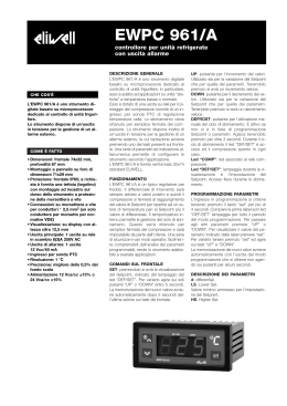
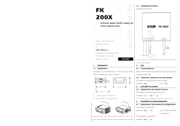
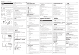
Evco S.p.A. • Code 104K411A01
EVK411
Single output digital thermoregulator for general purposes
GB ENGLISH
1
GETTING STARTED
1.1 Important
Read these instructions carefully before installing and using the instrument and follow all additional information for installation and electrical
connection; keep these instructions close to the instrument for future
consultations.
1.2 Installing the instrument
Panel mounting, with click brackets (supplied by the builder); dimensions in mm (in).
DIMENS.
A
B
MINIMUM
71.0 (2.795)
29.0 (1.141)
TYPICAL
71.0 (2.795)
29.0 (1.141)
MAXIMUM
71.8 (2.826)
29.8 (1.173)
Additional information for installation:
• 59.0 (2.322) is the maximum depth with screw terminal blocks
• 83.0 (3.267) is the maximum depth with extractable terminal blocks
• the panel thickness must not be higher than 8.0 mm (0.314 in)
• working conditions (working temperature, humidity, etc.) must be between the limits indicated in the technical data
• do not install the instrument close to heating sources (heaters, hot air
ducts, etc.), devices provided with big magnetos (big speakers, etc.),
locations subject to direct sunlight, rain, humidity, dust, mechanical
vibrations or bumps
• according to the safety legislation, the protection against electrical
parts must be ensured by a correct installation of the instrument; the
parts that ensure the protection must be installed so that you can not
remove them if not by using a tool.
1.3 Wiring diagram
With reference to the wiring diagram:
• terminals 1 and 2 are available only in the models with power supply
230 VAC and 115 VAC; terminals 8 and 9 are available only in the
models with power supply 12 VAC/DC and 12-24 VAC/DC
• the serial port (by request) is the port for the communication with the
supervision system (through a serial interface, via TTL, with MODBUS
communication protocol) or with the programming key; the port must
not be used at the same time for the same purposes.
Additional information for electrical connection:
• do not operate on the terminal blocks with electrical or pneumatic
screwers
• if the instrument has been moved from a cold location to a warm one,
the humidity could condense on the inside; wait about an hour before supplying it
• test the working power supply voltage, working electrical frequency
and working electrical power of the instrument; they must correspond
with the local power supply
• disconnect the local power supply before servicing the instrument
• do not use the instrument as safety device
• for repairs and information on the instrument please contact Evco
sales network.
2
USER INTERFACE
2.1 Turning on/off the instrument
To turn on the instrument you have to supply it; to turn it off it is enough
to cut off the power supply.
2.2 The display
If the instrument is turned on, during the normal operation the display
will show the quantity you have set with parameter P5:
• if P5 = 0, the display will show the room temperature
• if P5 = 1, the display will show the working setpoint.
2.3 Showing the room temperature
• make sure the keyboard is not locked and no procedure is running
2 s: the display will show “Pb1”
• press
• press
To quit the procedure:
• press
or do not operate 60 s
• press
or
as long as the display shows the quantity you have
set with parameter P5 or do not operate 60 s.
2.4 Activating the defrost by hand
• make sure the keyboard is not locked and no procedure is running
• press
4 s.
If parameter r5 has value 1 (heating action), the defrost functions will
not be enabled.
2.5 Locking/unlocking the keyboard
To lock the keyboard:
• make sure no procedure is running
• press
and
2 s: the display will show “Loc” 1 s.
If the keyboard is locked, you will not be allowed to:
• activate the defrost by hand
• modify the working setpoint with the procedure related in paragraph
4.1 (you also can modify the working setpoint through parameter SP).
These operations provoke the visualization of the label “Loc” 1 s.
To unlock the keyboard:
• press
and
2 s: the display will show “UnL” 1 s.
2.6 Silencing the buzzer
• make sure no procedure is running
• press a button (the first pressure of the button does not provoke its
usual effect).
3
OPERATION
3.1 Preliminary information
The operation mainly depends on parameter r5.
3.2 Operation with parameter r5 = 0 (cooling action)
3.3 Operation with parameter r5 = 1 (heating action)
4
SETTINGS
4.1 Setting the working setpoint
• make sure the keyboard is not locked and no procedure is running
• press
LED out 1 will flash
• press
or
in 15 s; also look at parameters r1, r2 and r3
• press
or do not operate 15 s.
You also can modify the working setpoint through parameter SP.
4.2 Setting configuration parameters
To gain access the procedure:
• make sure no procedure is running
• press
and
4 s: the display will show “PA”
• press
• press
or
in 15 s to set “-19”
or do not operate 15 s
• press
• press
and
4 s: the display will show “SP”.
To select a parameter:
• press
or
To modify a parameter:
• press
• press
or
in 15
• press
or do not operate 15 s.
To quit the procedure:
• press
and
4 s or do not operate 60 s.
Switch off/on the power supply of the instrument after the
modification of the parameters.
4.3 Restoring the default value of configuration parameters
• make sure no procedure is running
• press
and
4 s: the display will show “PA”
• press
• press
or
in 15 s to set “743”
version 1.01
• press
• press
• press
• press
• press
or do not operate 15 s
and
4 s: the display will show “dEF”
or
in 15 s to set “149”
or do not operate 15 s: the display will show “dEF” flashing 4 s, after which the instrument will quit the procedure
• switch off/on the power supply of the instrument.
Make sure the default value of the parameters is appropriate, in particular if the probes are NTC probes.
5
SIGNALS
5.1 Signals
LED
MEANING
out 1 LED load
if it is lit, the load will be turned on
if it flashes:
• the modification of the working setpoint will be running
• a load protection will be running (parameters C1 and C2)
LED defrost
if it is lit, the defrost will be running
LED alarm
if it is lit, an alarm will be running
°C
LED Celsius degree
if it is lit, the unit of measure of the temperatures will be
Celsius degree (parameter P2)
°F
LED Fahrenheit degree
if it is lit, the unit of measure of the temperatures will be
Fahrenheit degree (parameter P2)
CODE MEANING
Loc
the keyboard and/or the working setpoint are locked (parameter r3); also look at paragraph 2.5
6
ALARMS
6.1 Alarms
CODE MEANING
AL1
First temperature alarm
Remedies:
• check the room temperature
• look at parameters A1 and A3
Effects:
• no effect
AL2
Second temperature alarm
Remedies:
• check the room temperature
• look at parameters A5 and A7
Effects:
• no effect
When the cause that has provoked the alarm disappears, the instrument restores the normal operation.
7
INTERNAL DIAGNOSTICS
7.1 Internal diagnostics
CODE MEANING
Pr1
Room probe error
Remedies:
• look at parameter P0
• check the integrity of the probe
• check the connection instrument-probe
• check the room temperature
Effects:
• the load activity will depend on parameters C4 and C5
When the cause that has provoked the alarm disappears, the instrument restores the normal operation.
8
TECHNICAL DATA
8.1 Technical data
Box: self-extinguishing grey.
Frontal protection: IP 65.
Connections (use copper conductors only): screw terminal blocks
(power supply, input and output), 6 poles connector (serial port; by
request); extractable terminal blocks (power supply, input and output)
by request.
Working temperature: from 0 to 55 °C (32 to 131 °F, 10 ... 90% of
relative humidity without condensate).
Power supply: 230 VAC, 50/60 Hz, 3 VA (approximate); 115 VAC or
12-24 VAC/DC or 12 VAC/DC by request.
Insulation class: 2.
Alarm buzzer: by request.
Measure inputs: 1 (room probe) for PTC/NTC probes.
Working range: from -50.0 to 150.0 °C (-50 to 300 °F) for PTC probe,
from -40.0 to 105.0 °C (-40 to 220 °F) for NTC probe.
Resolution: 0.1 °C/1 °C/1 °F.
Digital outputs: 1 relay:
• load relay: 16 res. A @ 250 VAC (change-over
contact); 5 FLA, 30 LRA.
The maximum current allowed on the load is 10 A.
Serial port: port for the communication with the supervision system
(through a serial interface, via TTL, with MODBUS communication protocol) or with the programming key; by request.
I ITALIANO
1
PREPARATIVI
1.1 Importante
Leggere attentamente queste istruzioni prima dell’installazione e prima
dell’uso e seguire tutte le avvertenze per l’installazione e per il collegamento elettrico; conservare queste istruzioni con lo strumento per consultazioni future.
1.2 Installazione
A pannello, con le staffe a scatto in dotazione (si vedano i disegni del
paragrafo 1.2 della sezione in Inglese).
Avvertenze per l’installazione:
• 59,0 è la profondità massima con morsettiere a vite
• 83,0 è la profondità massima con morsettiere estraibili
• lo spessore del pannello non deve essere superiore a 8,0 mm
• accertarsi che le condizioni di lavoro (temperatura di impiego, umidità, ecc.) rientrino nei limiti indicati nei dati tecnici
• non installare lo strumento in prossimità di fonti di calore (resistenze,
condotti dell’aria calda, ecc.), di apparecchi con forti magneti (grossi
diffusori, ecc.), di luoghi soggetti alla luce solare diretta, pioggia, umidità, polvere eccessiva, vibrazioni meccaniche o scosse
• in conformità alle normative sulla sicurezza, la protezione contro eventuali contatti con le parti elettriche deve essere assicurata mediante
una corretta installazione dello strumento; tutte le parti che assicurano
la protezione devono essere fissate in modo tale da non poter essere
rimosse senza l’aiuto di un utensile.
1.3 Collegamento elettrico
Si veda il disegno del paragrafo 1.3 della sezione in Inglese.
Con riferimento allo schema elettrico:
• i morsetti 1 e 2 sono presenti solo nei modelli con alimentazione 230
VCA e 115 VCA; i morsetti 8 e 9 sono presenti solo nei modelli con
alimentazione 12 VCA/CC e 12-24 VCA/CC
• la porta seriale (su richiesta) è la porta per la comunicazione con il
sistema di supervisione (attraverso un’interfaccia seriale, via TTL, con
protocollo di comunicazione MODBUS) o con la chiave di programmazione; la porta non deve essere utilizzata contemporaneamente
per i due scopi.
Avvertenze per il collegamento elettrico:
• non operare sulle morsettiere utilizzando avvitatori elettrici o pneumatici
• se lo strumento è stato portato da un luogo freddo a uno caldo, l’umidità potrebbe condensare all’interno; attendere circa un’ora prima di
alimentarlo
• accertarsi che la tensione di alimentazione, la frequenza e la potenza
elettrica operativa dello strumento corrispondano a quelle dell’alimentazione locale
• disconnettere l’alimentazione prima di procedere con qualunque tipo
di manutenzione
• non utilizzare lo strumento come dispositivo di sicurezza
• per le riparazioni e per informazioni riguardanti lo strumento rivolgersi
alla rete di vendita Evco.
2
INTERFACCIA UTENTE
2.1 Accensione/spegnimento dello strumento
Per accendere lo strumento è necessario alimentarlo; per spegnerlo basta
togliere l’alimentazione.
2.2 Il display
Se lo strumento è acceso, durante il normale funzionamento il display
visualizzerà la grandezza stabilita con il parametro P5:
• se P5 = 0, il display visualizzerà la temperatura dell’ambiente
• se P5 = 1, il display visualizzerà il setpoint di lavoro.
2.3 Visualizzazione della temperatura dell’ambiente
• assicurarsi che la tastiera non sia bloccata e che non sia in corso alcuna procedura
• premere
per 2 s: il display visualizzerà “Pb1”
• premere
Per uscire dalla procedura:
• premere
o non operare per 60 s
• premere
o
fino a quando il display visualizza la grandezza
stabilita con il parametro P5 o non operare per
60 s.
2.4 Attivazione dello sbrinamento in modo manuale
• assicurarsi che la tastiera non sia bloccata e che non sia in corso alcuna procedura
• premere
per 4 s.
Se il parametro r5 è impostato a 1 (funzionamento per caldo), le funzioni dello sbrinamento non saranno abilitate.
2.5 Blocco/sblocco della tastiera
Per bloccare la tastiera:
• assicurarsi che non sia in corso alcuna procedura
• premere
e
per 2 s: il display visualizzerà “Loc” per 1 s.
Se la tastiera è bloccata, non sarà consentito:
• attivare lo sbrinamento in modo manuale
• modificare il setpoint di lavoro con la procedura indicata nel paragrafo
4.1 (il setpoint di lavoro è impostabile anche attraverso il parametro
SP).
Queste operazioni provocano la visualizzazione della label “Loc” per
1 s.
Per sbloccare la tastiera:
• premere
e
per 2 s: il display visualizzerà “UnL” per 1 s.
2.6 Tacitazione buzzer
• assicurarsi che non sia in corso alcuna procedura
• premere un tasto (la prima pressione del tasto non provoca l’effetto
associato).
3
FUNZIONAMENTO
3.1 Cenni preliminari
Il funzionamento dipende principalmente dal parametro r5.
3.2 Funzionamento con parametro r5 = 0 (funzionamento
per freddo)
Si veda il disegno del paragrafo 3.2 della sezione in Inglese.
3.3 Funzionamento con parametro r5 = 1 (funzionamento
per caldo)
Si veda il disegno del paragrafo 3.3 della sezione in Inglese.
4
IMPOSTAZIONI
4.1 Impostazione del setpoint di lavoro
• assicurarsi che la tastiera non sia bloccata e che non sia in corso alcuna procedura
• premere
il LED out 1 lampeggerà
• premere
o
entro 15 s; si vedano anche i parametri r1, r2 ed
r3
• premere
o non operare per 15 s.
È inoltre possibile impostare il setpoint di lavoro attraverso il parametro
SP.
4.2 Impostazione dei parametri di configurazione
Per accedere alla procedura:
• assicurarsi che non sia in corso alcuna procedura
• premere
e
per 4 s: il display visualizzerà “PA”
• premere
• premere
o
entro 15 s per impostare “-19”
• premere
o non operare per 15 s
• premere
e
per 4 s: il display visualizzerà “SP”.
Per selezionare un parametro:
• premere
o
Per modificare un parametro:
• premere
• premere
o
entro 15 s
• premere
o non operare per 15 s.
Per uscire dalla procedura:
e
per 4 s o non operare per 60 s.
• premere
Interrompere l'alimentazione dello strumento dopo la modifica dei parametri.
4.3 Ripristino del valore di default dei parametri di configurazione
• assicurarsi che non sia in corso alcuna procedura
• premere
e
per 4 s: il display visualizzerà “PA”
• premere
• premere
o
entro 15 s per impostare “743”
• premere
o non operare per 15 s
• premere
e
per 4 s: il display visualizzerà “dEF”
• premere
• premere
o
entro 15 s per impostare “149”
• premere
o non operare per 15 s: il display visualizzerà “dEF” lampeggiante per 4 s, dopodichè lo strumento uscirà dalla
procedura
• interrompere l'alimentazione dello strumento.
Accertarsi che il valore di default dei parametri sia opportuno, in particolare se le sonde sono di tipo NTC.
5
SEGNALAZIONI
5.1 Segnalazioni
LED
SIGNIFICATO
out 1 LED carico
se è acceso, il carico sarà acceso
se lampeggia:
• sarà in corso la modifica del setpoint di lavoro
• sarà in corso una protezione del carico (parametri C1 e C2)
LED sbrinamento
se è acceso, sarà in corso lo sbrinamento
LED allarme
se è acceso, sarà in corso un allarme
°C
LED grado Celsius
se è acceso, l’unità di misura delle temperature sarà il grado
Celsius (parametro P2)
°F
LED grado Fahrenheit
se è acceso, l’unità di misura delle temperature sarà il grado
Fahrenheit (parametro P2)
CODICE SIGNIFICATO
Loc
la tastiera e/o il setpoint di lavoro sono bloccati (parametro
r3); si veda il paragrafo 2.5
6
ALLARMI
6.1 Allarmi
CODICE SIGNIFICATO
AL1
Primo allarme di temperatura
Rimedi:
• verificare la temperatura dell’ambiente
• si vedano i parametri A1 e A3
Conseguenze:
• lo strumento continuerà a funzionare regolarmente
AL2
Secondo allarme di temperatura
Rimedi:
• verificare la temperatura dell’ambiente
• si vedano i parametri A5 e A7
Conseguenze:
• lo strumento continuerà a funzionare regolarmente
Quando la causa che ha provocato l’allarme scompare, lo strumento
ripristina il normale funzionamento.
7
DIAGNOSTICA INTERNA
7.1 Diagnostica interna
CODICE SIGNIFICATO
Pr1
Errore sonda ambiente
Rimedi:
• si veda il parametro P0
• verificare l’integrità della sonda
• verificare il collegamento strumento-sonda
• verificare la temperatura dell’ambiente
Conseguenze:
• l’attività del carico dipenderà dai parametri C4 e C5
Quando la causa che ha provocato l’allarme scompare, lo strumento
ripristina il normale funzionamento.
8
DATI TECNICI
8.1 Dati tecnici
Contenitore: autoestinguente grigio.
Grado di protezione del frontale: IP 65.
Connessioni (usare solo conduttori in rame): morsettiere a vite
(alimentazione, ingresso e uscita), connettore a 6 poli (porta seriale);
morsettiere estraibili (alimentazione, ingresso e uscita) su richiesta.
Temperatura di impiego: da 0 a 55 °C (10 ... 90% di umidità relativa senza condensa).
Alimentazione: 230 VCA, 50/60 Hz, 3 VA (approssimativi); 115 VCA
o 12-24 VCA/CC o 12 VCA/CC su richiesta.
Classe di isolamento: 2.
Buzzer di allarme: su richiesta.
Ingressi di misura: 1 (sonda ambiente) per sonde PTC/NTC.
Campo di misura: da -50,0 a 150,0 °C per sonda PTC, da -40,0 a
105,0 °C per sonda NTC.
Risoluzione: 0,1 °C/1 °C/1 °F.
Uscite digitali: 1 relè:
• relè carico: 16 A res. @ 250 VCA (contatto in scambio); 5 FLA, 30 LRA.
La corrente massima consentita sul carico è di 10 A.
Porta seriale: porta per la comunicazione con il sistema di supervisione
(attraverso un’interfaccia seriale, via TTL, con protocollo di comunicazione MODBUS) o con la chiave di programmazione; su richiesta.
9.1 Working setpoints
MIN. MAX. U.M.
DEF.
r1
r2
°C/°F (1) 0.0
9.2 Configuration parameters
PARAM. MIN. MAX. U.M.
DEF.
SP
r1
r2
°C/°F (1) 0.0
PARAM. MIN. MAX. U.M.
DEF.
CA1
-25.0 25.0
°C/°F (1) 0.0
P0
0
1
--0
WORKING SETPOINTS
working setpoint
WORKING SETPOINTS
working setpoint
MEASURE INPUTS
room probe offset
kind of probe
0 = PTC
1 = NTC
decimal point Celsius degree (for the quantity to
show during the normal operation)
1 = YES
unit of measure temperature (2)
0 = °C
1 = °F
quantity to show during the normal operation
0 = room temperature
1 = working setpoint
P1
0
1
---
1
P2
0
1
---
0
P5
0
1
---
0
PARAM. MIN.
r0
0.1
r1
-99.0
r2
r1
r3
0
MAX.
99.0
r2
(3)
1
U.M.
°C/°F (1)
°C/°F (1)
°C/°F (1)
---
r5
1
---
PARAM. MIN.
C1
0
MAX.
240
U.M.
min
C2
0
240
min
C3
C4
0
0
240
240
s
min
C5
0
240
min
PARAM. MIN.
d0
0
MAX.
99
U.M.
h
DEF.
MAIN REGULATOR
2.0
working setpoint differential
0.0
minimum working setpoint
150.0 maximum working setpoint
0
locking the working setpoint modification (with the
procedure related in paragraph 4.1)
1 = YES
(4)
cooling or heating action
0 = cooling
DEF.
LOAD PROTECTIONS
0
minimum time between two activations in succession of the load; also load delay since the end of
the room probe error (5)
0
minimum time the load remains turned off; also load
delay since you turn on the instrument
0
minimum time the load remains turned on
10
time the load remains turned off during the room
probe error; also look at C5
10
time the load remains turned on during the room
probe error; also look at C4
DEF.
DEFROST (6)
8
defrost interval (7)
0 = the defrost at intervals will never be activated
d3
0
99
min
0
d4
0
1
---
0
d5
0
99
min
0
d6
0
1
---
1
PARAM. MIN.
A1
-99.0
MAX.
(3)
U.M.
DEF.
°C/°F (1) 0.0
A2
A3
0
0
240
4
min
---
0
0
A4
0
240
min
0
A5
-99.0
(3)
°C/°F (1)
0.0
A6
A7
0
0
240
4
min
---
0
0
0
defrost duration
0 = the defrost will never be activated
defrost when you turn on the instrument
1 = YES
defrost delay when you turn on the instrument (only
if d4 = 1)
temperature shown during the defrost
0 = room temperature
1 = if to the defrost activation the room temperature is below “working setpoint + r0”, at most
“working setpoint + r0”; if to the defrost activation the room temperature is above “working
setpoint + r0”, at most the room temperature
to the defrost activation (8)
TEMPERATURE ALARMS
temperature the first temperature alarm is activated;
also look at A3 (9)
first temperature alarm delay (10)
kind of first temperature alarm
0 = alarm not enabled
1 = absolute lower alarm (or A1)
2 = absolute upper alarm (or A1)
3 = lower alarm relative to the working setpoint (or
"working setpoint - A1”; consider A1 without
sign)
4 = upper alarm relative to the working setpoint (or
"working setpoint + A1”; consider A1 without
sign)
temperature alarms delay since the working setpoint
modification (10)
temperature the second temperature alarm is activated; also look at A7 (9)
second temperature alarm delay (10)
kind of second temperature alarm
0 = alarm not enabled
1 = absolute lower alarm (or A5)
2 = absolute upper alarm (or A5)
3 = lower alarm relative to the working setpoint (or
"working setpoint - A5”; consider A5 without
sign)
4 = upper alarm relative to the working setpoint (or
"working setpoint + A5”; consider A5 without
sign)
ITALIANO
SETPOINT DI LAVORO E PARAMETRI
DI CONFIGURAZIONE
9.1 Setpoint di lavoro
SETPOINT DI LAVORO
setpoint di lavoro
9.2 Parametri di configurazione
SETPOINT DI LAVORO
setpoint di lavoro
INGRESSI DI MISURA
offset sonda ambiente
tipo di sonda
0 = PTC
1 = NTC
punto decimale grado Celsius (per la grandezza
visualizzata durante il normale funzionamento)
1 = SI
unità di misura temperatura (2)
0 = °C
1 = °F
grandezza visualizzata durante il normale funzionamento
0 = temperatura dell’ambiente
1 = setpoint di lavoro
REGOLATORE PRINCIPALE
differenziale del setpoint di lavoro
minimo setpoint di lavoro
massimo setpoint di lavoro
blocco della modifica del setpoint di lavoro (con la
procedura indicata nel paragrafo 4.1)
1 = SI
funzionamento per freddo o per caldo
0 = per freddo
PROTEZIONI DEL CARICO
tempo minimo tra due accensioni consecutive del
carico; anche ritardo carico dalla conclusione dell’errore sonda ambiente (5)
durata minima dello spegnimento del carico; anche ritardo carico dall’accensione dello strumento
durata minima dell’accensione del carico
durata dello spegnimento del carico durante l’errore sonda ambiente; si veda anche C5
durata dell’accensione del carico durante l’errore
sonda ambiente; si veda anche C4
SBRINAMENTO (6)
intervallo di sbrinamento (7)
0 = lo sbrinamento a intervalli non verrà mai attivato
durata dello sbrinamento
0 = lo sbrinamento non verrà mai attivato
sbrinamento all’accensione dello strumento
1 = SI
ritardo sbrinamento dall’accensione dello strumento (solo se d4 = 1)
temperatura visualizzata durante lo sbrinamento
0 = temperatura dell’ambiente
1 = se all’attivazione dello sbrinamento la temperatura dell’ambiente è al di sotto di “setpoint di
lavoro + r0”, al massimo “setpoint di lavoro +
r0”; se all’attivazione dello sbrinamento la temperatura dell’ambiente è al di sopra di “setpoint
di lavoro + r0”, al massimo la temperatura dell’ambiente all’attivazione dello sbrinamento (8)
ALLARMI DI TEMPERATURA
temperatura alla quale viene attivato il primo allarme di temperatura; si veda anche A3 (9)
ritardo primo allarme di temperatura (10)
tipo di primo allarme di temperatura
0 = allarme assente
1 = di minima assoluto (ovvero A1)
2 = di massima assoluto (ovvero A1)
3 = di minima relativo al setpoint di lavoro (ovvero
“setpoint di lavoro - A1”; considerare A1 senza
segno)
4 = di massima relativo al setpoint di lavoro (ovvero
“setpoint di lavoro + A1”; considerare A1 senza
segno)
ritardo allarmi di temperatura dalla modifica del
setpoint di lavoro (10)
temperatura alla quale viene attivato il secondo allarme di temperatura; si veda anche A7 (9)
ritardo secondo allarme di temperatura (10)
tipo di secondo allarme di temperatura
0 = allarme assente
1 = di minima assoluto (ovvero A5)
2 = di massima assoluto (ovvero A5)
3 = di minima relativo al setpoint di lavoro (ovvero
“setpoint di lavoro - A5”; considerare A5 senza
segno)
4 = di massima relativo al setpoint di lavoro (ovvero
“setpoint di lavoro + A5”; considerare A5 senza
segno)
9
I
PARAM. MIN.
LA
1
Lb
0
SERIAL NETWORK (MODBUS)
RETE SERIALE (MODBUS)
instrument address
indirizzo strumento
baud rate
baud rate
0 = 2,400 baud
0 = 2.400 baud
1 = 4,800 baud
1 = 4.800 baud
2 = 9,600 baud
2 = 9.600 baud
3 = 19,200 baud
3 = 19.200 baud
LP
0
2
--2
parity
parità
0 = none
0 = nessuna parità
1 = odd
1 = dispari
2 = even
2 = pari
PARAM. MIN. MAX. U.M.
DEF.
RESERVED
RISERVATO
E9
0
1
--1
reserved
riservato
(1)
the unit of measure depends on parameter P2
(1) l’unità di misura dipende dal parametro P2
(2)
set the parameters related to the regulators appropriately after the (2) impostare opportunamente i paramemodification of the parameter P2
tri relativi ai regolatori dopo la modi(3)
the value depends on parameter P2 (150.0 °C or 300 °F)
fica del parametro P2
(4)
the value depends on the instrument code, as follows:
(3) il valore dipende dal parametro P2 (150,0 °C
CODE
VALUE
o 300 °F)
EVK411???C*
r5 = 0 (cooling)
(4) il valore dipende dal codice dello strumento,
nel modo indicato:
EVK411??
r5 = 1 (heating)
CODICE
VALORE
EVK411???
r5 = 1 (heating)
EVK411???C*
r5 = 0 (per freddo)
EVK411???H?*
r5 = 1 (heating)
The question mark (?) replaces one field, the asterisk (*) replaces one or
EVK411??
r5 = 1 (per caldo)
more fields (or no-one); the field C means cooling, the field H means heating
EVK411???
r5 = 1 (per caldo)
(5)
if parameter C1 has value 0, the delay since the end of the room probe error will
EVK411???H?*
r5 = 1 (per caldo)
however be 2 min
Il punto di domanda (?) sostituisce un
(6)
if parameter r5 has value 1 (heating action), the defrost functions will not be enabled
campo, l’asterisco (*) sostituisce uno
o più campi (o nessuno); il campo C si(7)
the instrument stores the count of the defrost interval every 30 min; the modification of
gnifica cooling (per freddo), il campo H signiparameter d0 has effect since the end of the previous defrost interval or since the
fica heating (per caldo)
activation of a defrost by hand
(8)
the display restores the normal operation as soon as the defrost ends and the room (5) se il parametro C1 è impostato a 0, il ritardo
temperature falls below the one that has locked the display (or if a temperature alarm
dalla conclusione dell’errore sonda ambiente
sarà comunque di 2 min
arises)
(6) se il parametro r5 è impostato a 1 (funziona(9)
the differential of the parameter is 2.0 °C/4 °F
mento per caldo), le funzioni dello sbrinamento
(10)
during the defrost the temperature alarms are not enabled, on condition that they have
non saranno abilitate
arisen after the activation of the defrost.
(7) lo strumento memorizza il conteggio dell’intervallo di sbrinamento ogni 30 min; la modiThe instrument must be disposed according to the local legislation about the collection
fica del parametro d0 ha effetto dalla concluor electrical and electronic equipment.
sione del precedente intervallo di sbrinamento
Lo strumento deve essere smaltito secondo le normative locali in materia di raccolta
o dall’attivazione di uno sbrinamento in modo
delle apparecchiature elettriche ed elettroniche.
manuale
(8) il display ripristina il normale funzionamento
quando, concluso lo sbrinamento, la temperatura dell’ambiente scende al di sotto di quella che ha bloccato il display (o se si manifesta
un allarme di temperatura)
(9) il differenziale del parametro è di 2,0 °C/4 °F
(10) durante lo sbrinamento gli allarmi di temperatura sono assenti, a condizione che questi si
siano manifestati dopo l’attivazione dello
sbrinamento.
PT • 30/10
GB ENGLISH
9
WORKING SETPOINTS AND CONFIGURATION PARAMETERS
MAX.
247
3
U.M.
-----
DEF.
247
2
EVCO S.p.A.
Via Mezzaterra 6, 32036 Sedico Belluno ITALY
Phone +39-0437-852468 • Fax +39-0437-83648
[email protected] • www.evco.it
This document belongs to Evco; unless you are authorized by Evco, you can not publish it.
Evco does not take any responsibility about features, technical data and possible mistakes related in this document or coming by its use.
Evco does not take any responsibility about damages coming by the non-observance of the additional information.
Evco reserves the right to make any change without prior notice and at any time without prejudice the basic safety and operating features.
Scaricare