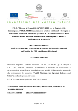
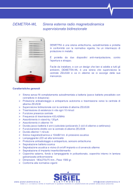
µC2
Manuale d’uso
User guide
Vogliamo farvi risparmiare tempo e denaro!
We wish to save you time and money!
Vi assicuriamo che la completa lettura di questo
manuale vi garantirà una corretta installazione ed
un sicuro utilizzo del prodotto descritto.
We can assure you that the thorough reading of
this manual will guarantee correct installation and
safe use of the product described.
AVVERTENZE IMPORTANTI
IMPORTANT WARNINGS
PRIMA DI INSTALLARE O INTERVENIRE SULL’APPARECCHIO,
LEGGERE ATTENTAMENTE E SEGUIRE LE ISTRUZIONI
CONTENUTE IN QUESTO MANUALE E NEL FOGLIO ISTRUZIONI
ALLEGATO AL PRODOTTO.
BEFORE INSTALLING OR WORKING ON THE APPLIANCE,
CAREFULLY READ AND OBSERVE THE INSTRUCTIONS
CONTAINED IN THIS MANUAL AND ON THE INSTRUCTION SHEET
ENCLOSED WITH THE PRODUCT.
3
µC2 - cod. +030220420 - rel. 1.0 - 26.05.04
INDICE
1.
1.1
1.2
INTRODUZIONE
Descrizione generale
Interfaccia utente
2.
2.1
2.2
CONTENTS
7
7
7
1.
1.1
1.2
INTRODUCTION
General description
User interface
7
7
7
COLLEGAMENTI
Schema generale
Struttura rete
10
10
11
2.
2.1
2.2
CONNECTIONS
General diagram
Network layout
10
10
11
3
APPLICAZIONI
12
3.
APPLICATIONS
12
4.
4.1
4.2
4.3
PARAMETRI
Parametri generali
Struttura menù
Tabelle parametri
26
26
27
28
4.
4.1
4.2
4.3
PARAMETERS
General parameters
Menu structure
Parameter tables
26
26
27
28
5.
DESCRIZIONE DEI PARAMETRI
39
5.
DESCRIPTION OF THE PARAMETERS
39
6.
TABELLA ALLARMI
64
6.
TABLE OF ALARMS
64
COLLEGAMENTI, ACCESSORI E OPZIONI DEL
CONTROLLO µC2
7.1 Schema di collegamento
7.2 Scheda espansione per µC2
7.3 EVD*: Driver per la valvola di espansione elettronica
7.4 Scheda gestione velocità ventilatori (cod. MCHRTF*)
7.5 Scheda gestione ON/OFF ventilatori (cod. CONVONOFF0)
7.6 Scheda di conversione PWM 0...10 Vdc (o 4...20 mA)
per ventilatori (cod.CONV0/10A0)
7.7 Calcolo della velocità minima e massima dei ventilatori
7.8 Chiave di programmazione (cod.PSOPZKEY00)
7.9 Opzione seriale RS485
7.10 Terminale remoto µC2
75
75
76
76
77
µC CONTROLLER CONNECTIONS,
ACCESSORIES AND OPTIONS
7.1 Connection diagram
7.2 Expansion board for µC2
7.3 EVD*: Electronic expansion valve driver
7.4 Fan speed control board (code MCHRTF*)
7.5 Fan ON/OFF control board(code CONVONOFF0)
7.6 PWM to 0 to 10 Vdc (or 4 to 20 mA) conversion board for
fans (code CONV0/10A0)
7.7 Minimum and maximum fan speed calculation
7.8 Programming key (code PSOPZKEY00)
7.9 RS485 serial options
7.10 Remote terminal for µC2
8.
DIMENSIONI
82
8.
DIMENSIONS
82
9.
CODICI
84
9.
CODES
84
10.
CARATTERISTICHE TECNICHE
85
10.
TECHNICAL SPECIFICATIONS
85
11.
AGGIORNAMENTI SOFTWARE
87
11
SOFTWARE UPDATES
87
7.
7.
69
69
71
74
74
75
2
69
69
71
74
74
75
75
75
76
76
77
5
µC2 - cod. +030220420 - rel. 1.0 - 26.05.04
1. INTRODUZIONE
1. INTRODUCTION
1.1 Descrizione generale
1.1 General description
µC2 è un nuovo controllo elettronico compatto CAREL, dalle dimensioni
di un normale termostato, per la completa gestione di chiller e pompe
di calore: offre la possibilità di gestire unità aria-aria, aria-acqua,
acqua-acqua e motocondensanti.
The µC2 is a new compact CAREL electronic controller, the same size
as a normal thermostat, for the complete management of chillers and
heat pumps: it can control air-air, air-water, water-water and condensing
units.
1.1.1 Funzioni principali
• Controllo sulla temperatura dell’acqua ingresso e uscita evaporatore;
• gestione dello sbrinamento a tempo e/o in temperatura o pressione;
• controllo della velocità dei ventilatori;
• completa gestione degli allarmi;
• collegabile a linea seriale per supervisione/teleassistenza;
• soppressione vaso di accumulo.
1.1.1 Main functions
• Control of the water inlet and evaporator outlet temperature;
• defrost management by time and/or by temperature or pressure;
• fan speed control;
• complete alarm management;
• connection to serial line for supervision/telemaintenance;
• elimination of the expansion vessel.
- Funzione Driver
• Gestione valvola di espansione elettronica.
- Driver function
• Management of electronic expansion valves.
1.1.2 Dispositivi controllati
• Compressore;
• ventilatori di condensazione;
• valvola di inversione ciclo;
• pompe di circolazione acqua per evaporatore e/o condensatore, e
ventilatore di mandata (aria-aria);
• resistenze antigelo;
• dispositivo di segnalazione di allarme.
1.1.2 Controlled devices
• Compressor;
• condenser fans;
• reversing valve;
• water pumps for evaporator and/or condenser, and outlet fan (air-air);
• antifreeze heater;
• alarm signal device.
1.1.3 Programmazione
CAREL offre la possibilità di configurare tutti i parametri della macchina
non solo tramite la tastiera posta sul frontale ma anche da:
• Chiave hardware;
• linea seriale.
1.1.3 Programming
CAREL offers the possibility to configure all the unit parameters not
only from the keypad on the front panel, but also using:
• A hardware key;
• a serial line.
1.2 Interfaccia utente
1.2 User interface
1.2.1 Display
Il display è composto da 3 cifre con la visualizzazione del punto
decimale tra -99.9 e 99.9.
All’esterno di tale campo di misura il valore viene automaticamente
mostrato senza decimale (sebbene al suo interno la macchina
funzioni sempre considerando la parte decimale).
In funzionamento normale il valore sul display corrisponde alla
temperatura letta dalla sonda B1, ovvero la temperatura acqua
ingresso evaporatore (nei refrigeratori d’acqua) oppure la temperatura
aria-ambiente nelle unità ad espansione diretta.
Di seguito nella Fig. 1.1, per la versione a pannello, e nella Fig. 1.2, per
la versione in guida DIN, vengono indicati i simboli presenti nel display
e sulla tastiera e il loro significato.
1.2.1 Display
The display features 3 digits, with the display of the decimal point
between -99.9 and 99.9.
Outside of this range of measurement, the value is automatically
displayed without the decimal (even if internally the unit still operates
considering the decimal part).
In normal operation, the value displayed corresponds to the temperature
read by probe B1, that is, the evaporator water inlet temperature (for
water chillers) or the ambient air temperature for direct expansion units.
Fig. 1.1, for the panel version, and Fig. 1.2, for the DIN rail version,
show the symbols present on the display and on the keypad and their
meanings.
1.2.2 Simbologia Display
Display a 3 cifre di colore verde (più segno e punto decimale),
simbologia color ambra con simbolo di allarme di colore rosso.
1.2.2 Symbols on the display
Display with 3 green digits (plus sign and decimal point), amber
symbols and red alarm symbols.
7
µC2 - cod. +030220420 - rel. 1.0 - 26.05.04
Fig. 1.2.1.1
Fig. 1.2.1.2
Simbolo
Symbol
Colore
Colour
Significato
Meaning
con LED acceso
with LED ON
1; 2
3; 4
con LED lampeggiante
with LED flashing
Ambra
Compressore 1 e/o 2 acceso
Amber
Compressor 1 and/or 2 ON
Ambra
Compressore 3 e/o 4 acceso
Amber
Compressor 3 and/or 3 ON
Ambra
Almeno un compressore acceso
Amber
At least one compressor ON
Ambra
Pompa/ventilatore aria mandata accesa/o
Amber
Pump/air outlet fan ON
Ambra
Ventilatore di condensazione attivato
Amber
Condenser fan ON
Ambra
Defrost attivo
Amber
Defrost active
Ambra/Amber
Resistenza attivata/Heater ON
Rosso/Red
Ambra
Amber
Ambra
Amber
Allarme attivo/Alarm active
Modalità pompa di calore (P6=0)
Heat pump mode (P6=0)
Modalità chiller (P6=0)
Chiller mode (P6=0)
Circuito frigorifero di riferimento
Reference refrigerant circuit
Richiesta di accensione
Start up request
Richiesta di accensione
Start up request
1
2
1/2
Richiesta accensione
Start up request
1/2
1/2
Richiesta Defrost
Defrost request
1/2
1/2
Richiesta modalità pompa di calore (P6=0)
Heat pump mode request (P6=0)
Richiesta modalità chiller (P6=0)
Chiller mode request (P6=0)
1/2
1/2
1/2
Tab. 1.2.2
8
µC2 - cod. +030220420 - rel. 1.0 - 26.05.04
1.2.3. Funzioni associate ai tasti
1.2.3. Functions associated with the buttons
Tasto
Button
Stato della macchina
Unit status
Modalità pressione
Button press mode
Caricamento valori di default
Loading default values
Ritorno al sottogruppo superiore all’interno dell’ambiente di programmazione fino
all’uscita (con salvataggio variazioni in EEPROM)
Go up a sub-group inside the programming area, until exiting (saving changes to EEPROM)
In caso di allarme attivo spegne il buzzer (se presente) e disattiva il relè di allarme
In the event of alarms, mute the buzzer (if present) and deactivate the alarm relay
Accesso a parametri direct/Access the direct parameters
Selezione voce all’interno dell’ambiente di programmazione e visualizzazione
valore parametri direct/conferma della variazione del parametro
Select item inside the programming area and display value of direct
parameters/confirm the changes to the parameters
Programmazione parametri mediante inserimento password
Program parameters afters entering password
Selezione voce superiore all’interno dell’ambiente di programmazione
Select top item inside the programming area
Incremento valore
Increase value
Passaggio da stand-by a modalità refrigeratore (P6=0) e viceversa
Switch from standby to chiller mode (P6=) and vice versa
Selezione voce inferiore all’interno dell’ambiente di programmazione
Select bottom item inside the programming area
Decremento valore
Decrease value
Passaggio da stand-by a modalità pompa di calore (P6=0) e viceversa
Switch from standby to heat pump mode (P6=0) and vice versa
Riarmo manuale allarmi/Manual alarm reset
Azzeramento immediato del contaore (all’interno dell’ ambiente di programmazione)
Immediately reset the hour counter (inside the programming area)
Forza sbrinamento manuale per entrambi i circuiti
Force manual defrost on both circuits
Accensione con tasto premuto
Press at power ON
Pressione singola
Press once
Pressione singola
Press once
Pressione per 5 s/Press for 5 s
Pressione singola
Press once
Pressione per 5 s
Press for 5 s
Pressione singola o continua
Press once or press and hold
Pressione singola o continua
Press once or press and hold
Pressione per 5 s
Press for 5 s
Pressione singola o continua
Press once or press and hold
Pressione singola o continua
Press once or press and hold
Pressione per 5 s
Press for 5 s
Pressione per 5 s/Press for 5 s
Pressione per 5 s
Press for 5 s
Pressione per 5 s
Press for 5 s
Tab 1.2.3
1.2.4 Procedura programmazione e salvataggio parametri
1.2.4 Programming and saving the parameters
1: Premere “
” e “sel” per 5 s;
2: appare il simbolo di caldo e freddo e la cifra “00”;
3: impostare tramite “
”e“
” la password (pag 28) e confermare
con “sel”;
4: selezionare tramite “ ” e “
” il menù parametri (S-P) o livelli
(L-P) con “sel”;
5: selezionare tramite “
”e“
” il gruppo parametri con “sel”;
6: selezionare tramite “ ” e “
” il parametro con “sel”;
7: dopo la modifica del parametro premere “sel” per confermare o
“
” per annullare la modifica;
1: Press “
” and “sel” for 5 seconds;
2: the heating and cooling symbol and the figure “00” are displayed;
3: use “
” and “
” to set the password (page 28) and confirm by
pressing “sel”;
4: use “ ” and “
” to select the parameter menu (S-P) or levels
(L-P) and then press “sel”;
5: use “ ” and “ ” to select the parameter group and then press “sel”;
6: use “
” and “
” to select the parameter and then press “sel”;
7: after making the changes to the parameter, press “sel” to confirm
or “
” to cancel the changes;
8: premere “
8: press “
” to return to the previous menu;
9: to save the modifications, press “
” repeatedly until reaching the
main menu.
” per ritornare al menù precedente;
9: per salvare le modifiche premere più volte “
principale.
” fino al menù
Note:
a: I parametri modificati senza l’avvenuta conferma tramite il tasto “sel”
ritornano al valore precedente
b: Se per 60 s non si effettuano operazioni da tastiera, il controllo esce
dal menù modifica parametri per time-out e le modifiche vengono
annullate
Note:
a: The parameters that have been modified without being confirmed
using the “sel” button return to the previous value
b: If no operations are performed on the keypad for 60 seconds, the
controller exits the parameter modification menu by timeout and the
changes are cancelled
1.2.5. Tastiera
1.2.5. Keypad
La tastiera permette l’impostazione dei valori di funzionamento della
macchina (vedi parametri/allarmi - Combinazione tasti)
The keypad is used to set the unit operating values (see
Parameters/alarms - Keypad combinations)
9
µC2 - cod. +030220420 - rel. 1.0 - 26.05.04
2. COLLEGAMENTI
2.CONNECTIONS
2.1 Schema generale
2.1 General diagram
EV driver
EV driver
ESP.
Fig. 2.1.1
EV driver
EV driver
ESP.
Fig. 2.1.2
10
µC2 - cod. +030220420 - rel. 1.0 - 26.05.04
2.2 Struttura rete
2.2 Network layout
EV driver
Fig. 2.2.1
EV driver
DIN
EV driver
Fig. 2.2.2
11
µC2 - cod. +030220420 - rel. 1.0 - 26.05.04
3. APPLICAZIONI
3.APPLICATIONS
3.1 Unità ARIA/ARIA, monocircuito
3.1 Air/air unit, single circuit
Sonda mandata
Supply probe
B2
Resistenza di riscaldamento
Electrical heater
Fig. 3.1.1
3.2 Unità ARIA/ARIA, bicircuito
3.2 Air/air unit, two circuits
Sonda mandata
Supply probe
B2
Fig. 3.2.1
12
µC2 - cod. +030220420 - rel. 1.0 - 26.05.04
3.3 Unità ARIA/ARIA, bicircuito, 1 circuito di
ventilazione di condensazione
3.3 Air/air unit, two circuits, 1 condenser fan circuit
Sonda mandata
Supply probe
B2
b
Fig. 3.3.1
3.4 Pompa di calore ARIA/ARIA, monocircuito
3.4 AIR/AIR heat pump, single circuit
Sonda mandata
Supply probe
B2
Fig. 3.4.1
13
µC2 - cod. +030220420 - rel. 1.0 - 26.05.04
3.5 Pompa di calore ARIA/ARIA, bicircuito
3.5 AIR/AIR heat pump, two circuits
Sonda mandata
Supply probe
B2
Fig. 3.5.1
3.6 Pompa di calore ARIA/ARIA bicircuito, 1 circuito di
ventilazione di condensazione
3.6 AIR/AIR heat pump two circuits, 1 condenser fan
circuit
p
p
Sonda mandata
Supply probe
B2
Fig. 3.6.1
14
µC2 - cod. +030220420 - rel. 1.0 - 26.05.04
3.7 Chiller ARIA/ACQUA, monocircuito
3.7 AIR/WATER chiller, single circuit
Fig. 3.7.1
3.9 Chiller ARIA/ACQUA, bicircuito, 2 circuiti di
ventilazione di condensazione e 2 evaporatori
3.9 AIR/WATER chiller, two circuits, 2 condenser fa
circuits and 2 evaporators
Fig. 3.9.1
15
µC2 - cod. +030220420 - rel. 1.0 - 26.05.04
3.10 Chiller ARIA/ACQUA bicircuito, 1 circuito di
ventilazione di condensazione
3.10 AIR/WATER chiller two circuits, 1 condenser
fan circuit
Fig. 3.10.1
3.11 Pompa di calore ARIA/ACQUA, monocircuito
3.11 AIR/WATER heat pump, single circuit
Fig. 3.11.1
16
µC2 - cod. +030220420 - rel. 1.0 - 26.05.04
3.12 Pompa di calore ARIA/ACQUA, 2 circuiti di
ventilazione condensazione
3.12 AIR/WATER heat pump, 2 condenser fan circuits
Fig. 3.12.1
3.13 Pompa di calore ARIA/ACQUA, bicircuito,
1 circuito di ventilazione di condensazione
3.13 AIR/WATER heat pump, two circuits, 1 condenser
fan circuit
Fig. 3.13.1
17
µC2 - cod. +030220420 - rel. 1.0 - 26.05.04
3.14 Chiller ACQUA/ACQUA, monocircuito
3.14 WATER/WATER chiller, single circuit
Fig. 3.14.1
3.15 Chiller ACQUA/ACQUA bicircuito
3.15 WATER/WATER chiller two circuits
2
2
Fig. 3.15.1
18
µC2 - cod. +030220420 - rel. 1.0 - 26.05.04
3.16 Chiller ACQUA/ACQUA, bicircuito, 1 evaporatore
3.16 WATER/WATER chiller, two circuits, 1 evaporator
Fig. 3.16.1
3.17 Pompa di calore ACQUA/ACQUA a reversibilità
del gas, monocircuito
3.17 WATER/WATER heat pump with reversal on gas
circuit, single circuit
Fig. 3.17.1
19
µC2 - cod. +030220420 - rel. 1.0 - 26.05.04
3.18 Pompa di calore ACQUA/ACQUA a reversibilità
del gas, bircuito
3.18 WATER/WATER heat pump with reversal on gas
circuit, two circuits
Fig. 3.18.1
3.19 Pompa di calore ACQUA/ACQUA a reversibilità
del gas, bicircuito, 1 evaporatore
3.19 WATER/WATER heat pump with reversal on gas
circuit, two circuits, 1 evaporator
Flussostato
Flow detector
Fig. 3.19.1
20
µC2 - cod. +030220420 - rel. 1.0 - 26.05.04
3.20 Pompa di calore ACQUA/ACQUA a reversibilità
dell’acqua, monocircuito
3.20 WATER/WATER heat pump with reversal on water
circuit, single circuit
Fig. 3.20.1
3.21 Pompa di calore ACQUA/ACQUA a reversibilità
dell’acqua, bicircuito, H02= 1 e H21= 4
3.21 WATER/WATER heat pump with reversal on water
circuit, two circuits, H02= 1 e H21= 4
cooling
cooling
Fig. 3.21.1
21
µC2 - cod. +030220420 - rel. 1.0 - 26.05.04
3.22 Pompa di calore ACQUA/ACQUA a reversibilità
dell’acqua, bicircuito, 1 evaporatore H02= 1 e H21= 4
3.22 WATER/WATER heat pump with reversal on water
circuit, two circuits, 1 evaporator H02= 1 e H21= 4
Fig. 3.22.1
3.23 Motocondensante ad aria senza inversione di
ciclo, monocircuito
3.23 Air-cooled condensing unit without reverse cycle,
single circuit
Fig. 3.23.1
22
µC2 - cod. +030220420 - rel. 1.0 - 26.05.04
3.24 Air-cooled condensing unit without reverse cycle,
two circuits
3.24 Motocondensante ad aria senza inversione di
ciclo, bicircuito
Fig. 3.24.1
3.25 Reverse-cycle air-cooled condensing unit, single
circuit
3.25 Motocondensante ad aria con inversione di ciclo,
monocircuito
Fig. 3.25.1
23
µC2 - cod. +030220420 - rel. 1.0 - 26.05.04
3.26 Motocondensante ad aria con inversione di ciclo,
bicircuito con un circuito ventilazione di condensazione
3.26 Reverse-cycle air-cooled condensing unit, two
circuits with one condenser fan circuit
Fig. 3.26.1
3.27 Motocondensante ad acqua senza inversione di
ciclo, monocircuito
3.27 Water-cooled condensing unit without reverse
cycle, single circuit
Fig. 3.27.1
24
µC2 - cod. +030220420 - rel. 1.0 - 26.05.04
3.28 Motocondensante ad acqua senza inversione di
ciclo, bicircuito
3.28 Water-cooled condensing unit without reverse
cycle, two circuits
B7
Fig. 3.28.1
3.29 Motocondensante ad acqua con inversione di
ciclo, monocircuito
3.29 Reverse-cycle water-cooled condensing unit,
single circuit
Fig. 3.29.1
25
µC2 - cod. +030220420 - rel. 1.0 - 26.05.04
3.30 Motocondensante ad acqua con inversione di
ciclo, bicircuito
3.30 Reverse-cycle water-cooled condensing unit, two
circuits
2
1
2
1
2
2
1
1
Fig. 3.30.1
4. Parametri
4.Parameters
4.1 Parametri generali
4.1 General parameters
I parametri si dividono in 4 diverse tipologie a seconda della loro
accessibilità da parte dell’utente tramite password e della loro funzione.
Da ciascun livello è possibile impostare l’accessibilità ai soli parametri
del proprio livello a livelli inferiori.
Questo implica che con password “Factory”, accedendo al menù livelli
(L-P), è possibile impostare per ciascun parametro il livello desiderato.
The parameters are divided into 4 different types, according to their
level of access by the user (password) and their function.
For each level, only the access to the parameters of the same or lower
level can be set.
This means that through “factory” password, acessing the menù “levels”
(L-P), it is possible to set the desired level for each parameter.
• Parametri Factory
Accessibili con password 66 “Factory”, permettono la configurazione
di tutti i parametri dell’unità.
• Factory parameters
Accessible with the 66 “Factory” password, allow the configuration of
all the unit parameters.
• Parametri Super User
Accessibili con password 11 “Super User”, permettono la
configurazione dei parametri Super User, User e Direct.
• Super User parameters
Accessible with the 11 “Super User” password, allow the configuration
of the Super User, User and Direct parameters.
• Parametri User
Accessibili tramite password 22, permettono la configurazione di quei
parametri tipicamente impostabili da utente (solo User) e Direct,
relative quindi alle opzioni.
• User parameters
Accessible with password 22, allow the configuration of the
parameters that typically can be set by the user (User parameters)
and the Direct parameters, consequently relating to the options.
• Parametri Direct
Accessibili senza password, permettono la lettura di sonde ed
eventuali dati, che possono essere interrogate da chiunque senza
compromettere il funzionamento dell’unità.
• Direct parameters
Accessible without password, this are used to read the probe
measurements and any data, by any user, without compromising the
operation of the unit.
N.B.: Le variazioni dei parametri riguardanti la configurazione
della macchina (tipologia, numero compressori,…) vanno eseguite
con controllo in stato di Stand by.
N.B.: The modifications to the parameters regarding the
configuration of the unit (type, number of compressors,…) must
be performed with the controller in Standby.
26
µC2 - cod. +030220420 - rel. 1.0 - 26.05.04
4.2 Struttura menù
4.2 Menu structure
Menù principale
Main Menù
And
Save in the EEPROM
Livello
Level
_d_
_U_
_S_
_F_
For 5”
For 5”
Nome Livello
Level name
Direct
User
Super User
Factory
Password
No password
22
11
66
Inserimento Password
Setting Password
Valore Parametri
Parameter Values
Or
Or
Livello Parametri
Parameter Level
Parametri /*
Parameters /*
Parametri A*
Parameters A*
Parametri F-r*
Parameters F-r*
Parametri r*
Parameters r*
Parametri b*
Parameters b*
Parametri c*
Parameters c*
Parametri P*
Parameters P*
Parametri d*
Parameters d*
Parametri H*
Parameters H*
Parametri F*
Parameters F*
Valore parametri F1
Parameter Values F1
Valore Livello F1
Level Value F1
Parametri F1
Parameters F1
Or
Parametri Fn
Parameters Fn
Fig. 4.2
27
µC2 - cod. +030220420 - rel. 1.0 - 26.05.04
4.3 Tabelle parametri
4.3 Parameter tables
Di seguito sono riportate le tabelle dei parametri suddivise per tipo di
famiglia (es. compressore, sonde, ventilatori ecc.).
The following tables show of the parameters divided by type/family (e.
g. compressor, probes, fans etc.).
• Legenda tabella parametri
Livello (default)
U= user
S= super user
F= factory
• Key to the parameter tables
Level (default)
U= user
S= super user
F= factory
Visibilità:
La visibilità di alcuni gruppi è condizionata dal tipo di controllo e dal
valore dei parametri.
D= sbrinamento (se D01=1)
F= ventilatore (se F01=1)
N= sonda NTC (se /04-/08=2)
P= pressione (se /04-/08=3)
V= driver (se H08 =1-3)
X= espansione (se H08=2-3)
- = sempre presente
Visibility:
The visibility of some groups depends on the type of controller and the
value of the parameters.
D= defrost (if D01=1)
F= fan (if F01=1)
N= NTC probe (if /04-/08=2)
P= pressure (if /04-/08=3)
V= driver (if H08 =1-3)
X= expansion (if H08=2-3)
- = always present
Variabile Supervisore:
R/W = parametro di lettura/scrittura a supervisore
R = parametro di sola lettura a supervisore
Supervisor variables:
R/W= supervisor read/write parameter
R= supervisor read-only parameter
4.3.1 Parametri impostazione sonde: (/*)
4.3.1 Probe setting parameters: (/*)
Indicaz.
Parametro e descrizione
Display
Parameter and description
Display
Indication
/01
/02
/03
/04
/05
/06
/07
/08
/09
/10
Parametri impostazione sonde/Probe setting parameters
Livello Min. Max. U.M.
Variazione Default
Default Min. Max. U.O.M.
Variation Default
Default
Level
Tipo sonda B1/Probe type B1
0= Non presente/not present
1= Presente/present
Tipo sonda B2/Probe type B2
0= Non presente/not present
1= Presente/present
Tipo sonda B3/Probe type B3
0= Non presente/not present
1= NTC Sonda Cond./NTC Cond. Probe
2= NTC Sonda ext. /NTC Out. Probe
Tipo sonda B4/Probe Type B4
0= Non presente/not present
1= ON/OFF (D.I)
2= NTC Sonda ext. /Out. probe
3= Sonda raziometrica cond. 5 Vdc
Ratiometric cond. Probe, 5 Vdc
Tipo sonda B5/Probe Type B5
0= Non presente/not present
1= Presente/present
Tipo sonda B6/Probe Type B6
0= Non presente/not present
1= Presente/present
Tipo sonda B7/Probe Type B7
0= Non presente/not present
1= NTC Sonda Cond./NTC Cond. Probe
2= NTC Sonda ext./NTC Out. Probe
Tipo sonda B8 (espansione)
Type of probe B8 (expansion)
0= Non presente/not present
1= ON/OFF
2= NTC Sonda ext/Out. probe
3= Sonda Raziometrica Cond. 5 Vdc
Ratiometric cond. probe, 5 Vdc
Valore minimo ingresso in tensione
Min. value voltage input
Valore massimo ingresso in tensione
Max. value voltage input
Visibilità Variabile Tipo
Visibility Superv. Variabile.
Supervis. Variabile
Variable Type
F
0
1
Flag
1
1
-
1 (R/W)
Digital
F
0
1
Flag
1
0
-
2 (R/W)
Digital
F
0
2
Flag
1
0
-
14 (R/W) Integear
F
0
3
Flag
1
0
-
15 (R/W) Integear
F
0
1
Flag
1
0
X
3 (R/W)
Digital
F
0
1
Flag
1
0
X
4 (R/W)
Digital
F
0
2
Flag
1
0
X
16 (R/W) Integear
F
0
3
Flag
1
0
X
17 (R/W) Integear
F
0
/10
0.01 Vdc 1
50
P
18 (R/W) Integear
F
/09
500
0.01 Vdc 1
450
P
19 (R/W) Integear
continua.../continues...
28
µC2 - cod. +030220420 - rel. 1.0 - 26.05.04
Indicaz. Parametro e descrizione
Display Parameter and description
Display
Indication
/11
/12
/13
/14
/15
/16
/17
/18
/19
/20
/21
/22
/23
Parametri impostazione sonde/Probe setting parameters
Livello Min.
Max. U.M.
Variazione Default Visibilità Variabile Tipo
Default Min.
Max. U.O.M.
Variation Default Visibility Superv. Variabile.
Default
Supervis. Variabile
Level
Variable Type
Valore minimo pressione/Pressure min. value
Valore massimo pressione/Pressure max. value
Calibrazione sonda B1/Probe B1 calibration
Calibrazione sonda B2/Probe B2 calibration
Calibrazione sonda B3/Probe B3 calibration
Calibrazione sonda B4/Probe B4 calibration
Calibrazione sonda B5/Probe B5 calibration
Calibrazione sonda B6/Probe B6 calibration
Calibrazione sonda B7/Probe B7 calibration
Calibrazione sonda B8/Probe B8 calibration
Filtro digitale/Digital filter
Limitazione ingresso/Input limitation
Unità di misura/Unit of measure
0= °C
1= °F
F
F
F
F
F
F
F
F
F
F
U
U
U
0
/11
-12.0
-12.0
-12.0
-12.0
-12.0
-12.0
-12.0
-12.0
1
1
0
/12
99.9
12.0
12.0
12.0
12.0
12.0
12.0
12.0
12.0
15
15
1
bar
bar
°C/°F
°C/°F
°C/°F
°C/bar/°F
°C/°F
°C/°F
°C/°F
°C/bar/°F
Flag
1
1
0.1
0.1
0.1
0.1
0.1
0.1
0.1
0.1
1
1
1
0
34.5
0.0
0.0
0.0
0.0
0.0
0.0
0.0
0.0
4
8
0
P
P
X
X
X
X
-
1 (R/W)
2 (R/W)
3 (R/W)
4 (R/W)
5 (R/W)
6 (R/W)
7 (R/W)
8 (R/W)
9 (R/W)
10 (R/W)
20 (R/W)
21 (R/W)
5 (R/W)
Analog
Analog
Analog
Analog
Analog
Analog
Analog
Analog
Analog
Analog
Integear
Integear
Digital
Tab. 4.3.1
4.3.2 Parametri impostazione antigelo-resistenze appoggio (A*)
4.3.2 Antifreeze/auxiliary heater setting parameters (A*)
Parametri impostazione antigelo-resistenze di appoggio /Antifreeze/auxiliary heater setting parameters
Indicaz. Parametro e descrizione
Livello Min. Max. U.M.
Variazione Default Visibilità Variabile
Display Parameter and description
Default Min. Max. U.O.M.
Variation Default Visibility Superv.
Display
Default
Supervis.
Indication
Level
Variable
A01
A02
A03
A04
A05
A06
A07
A08
A09
A10
Set allarme antigelo/bassa temp. amb. (Aria/Aria)
Antifreeze/low ambient temp. (air/air) alarm
set point
Differenziale allarme antigelo/bassa
temperatura ambiente (Aria/Aria)
Differential for antifreeze/low ambient
temperature alarm
Tempo bypass allarme antigelo/bassa temp.
ambiente all'accensione della macchina in Inverno
Bypass time for antifreeze alarm/low ambient temp.
when turning on the unit in heating mode
Set resistenza antigelo/appoggio
Set point for the activation of antifreeze
heater/auxiliary heater
Differenziale resistenza antigelo/appoggio
Diff. for antifreeze heater/auxiliary heater
Sonda resistenze di appoggio
Auxiliary heater probe
0= Sonda di controllo vedi (Tab. 5.1)
Control probe see (Tab. 5.1)
1= Sonda antigelo vedi (Tab 5.1)
Antifreeze probe see (Tab. 5.1)
Limite set allarme antigelo
Antifreeze alarm set point limit
Set resistenza di appoggio in riscaldamento
Auxiliary heater set point in heating mode
Diff. Resistenza di appoggio in riscaldamento
Auxiliary heater differential in heating mode
Accensione automatica antigelo
Antifreeze automatic start up
0= Funzione disabilitata/disabled function
1= Resistenze e pompa accese
contemporaneamente su A4/A8
Heaters and pump on at the same time on A4/A8
2= Resistenze e pompa accese
indipendentemente su A4/A8
Heaters and pump on indipendently on A4/A8
3= Resistenze accese su A4/A8
Heaters ON on A4/A8
U
A07
A04
U
0.3
0.3
U
0.1
3.0
-
11 (R/W) Analog
°C
122.0 °F
0.1
5.0
-
12 (R/W) Analog
0
150
S
1
0
-
22 (R/W) Integear
U
A01
r16
°C/°F
0.1
5.0
-
13 (R/W) Analog
U
0.3
50.0 °C/°F
0.1
1.0
-
14 (R/W) Analog
F
0
1
1
0
-
6 (R/W)
F
0.1
-40.0
-
15 (R/W) Analog
0.1
25.0
-
16 (R/W) Analog
U
-40.0
°C
-40.0 176.0 °F
A01 r15 °C
°F
0.3
50.0 °C/°F
0.1
3.0
-
17 (R/W) Analog
U
0
1
0
-
23 (R/W) Integear
U
3
°C/°F
Tipo
Variabile.
Variabile
Type
Flag
Flag
Digital
Tab. 4.3.2
29
µC2 - cod. +030220420 - rel. 1.0 - 26.05.04
4.3.3 Parametri lettura sonde (B*)
Indicaz. Parametro e descrizione
Display Parameter and description
Display
Indication
b00
b01
b02
b03
b04
b05
b06
b07
b08
b09
b10
b11
b12
b13
b14
b15
b16
b17
b18
b19
b20
4.3.3 Probe reading parameters (B*)
Parametri lettura sonde/Probe reading parameters
Livello Min. Max. U.M.
Variazione Default Visibilità Variabile Tipo
Default Min. Max. U.O.M.
Variation Default Visibility Superv. Variabile.
Default
Supervis. Variabile
Level
Variable Type
Selezione sonda da visualizzare sul display
Config. of probe to be shown on the display
Valore letto dalla sonda B1
Value read by probe B1
Valore letto dalla sonda B2
Value read by probe B2
Valore letto dalla sonda B3
Value read by probe B3
Valore letto dalla sonda B4
Value read by probe B4
Valore letto dalla sonda B5
Value read by probe B5
Valore letto dalla sonda B6
Value read by probe B6
Valore letto dalla sonda B7
Value read by probe B7
Valore letto dalla sonda B8
Value read by probe B8
Temperatura evaporatore Driver 1
Driver 1 evaporator temperature
Pressione evaporatore Driver 1
Driver 1 evaporator pressure
Surriscaldamento Driver 1
Driver 1 superheating
Temperatura saturazione Driver 1
Driver 1 saturation temperature
Posizione valvola Driver 1
Driver 1 valve position
Temperatura evaporatore Driver 2
Driver 2 evaporator temperature
Pressione evaporatore Driver 2
Driver 2 evaporator pressure
Surriscaldamento Driver 2
Driver 2 superheating
Temperatura saturazione Driver 2
Driver 2 saturation temperature
Posizione valvola Driver 2
Driver 2 valve position
Sonda temp. uscita scambiatore esterno c1
Temp. probe at the outlet of the external coil c1
Sonda temp. uscita scambiatore esterno c2
Temp. probe at the outlet of the external coil c12
U
0
9
Flag
1
0
-
24 (R/W) Integear
D
-
-
°C /°F
-
-
-
70 (R)
Analog
D
-
-
°C /°F
-
-
-
71 (R)
Analog
D
-
-
°C /°F
-
-
-
72 (R)
Analog
D
-
-
-
-
-
73 (R)
Analog
D
-
-
°C /°F/
bar
°C /°F
-
-
X
74 (R)
Analog
D
-
-
°C /°F
-
-
X
75 (R)
Analog
D
-
-
°C /°F
-
-
X
76 (R)
Analog
D
-
-
-
-
X
77 (R)
Analog
D
-
-
°C /°F
bar
°C /°F
-
-
V
78 (R)
Analog
D
-
-
bar
-
-
V
79 (R)
Analog
D
-
-
°C /°F
-
-
V
80 (R)
Analog
D
-
-
°C /°F
-
-
V
81 (R)
Analog
D
0
100.0 %
-
-
V
82 (R)
Analog
D
-
-
°C /°F
-
-
XV
83 (R)
Analog
D
-
-
bar
-
-
XV
84 (R)
Analog
D
-
-
°C /°F
-
-
XV
85 (R)
Analog
D
-
-
°C /°F
-
-
XV
86 (R)
Analog
D
0
100.0 %
-
-
XV
87 (R)
Analog
D
-
-
°C /°F
-
-
V
88 (R)
Analog
D
-
-
°C /°F
-
-
XV
89 (R)
Analog
Tab. 4.3.3
30
µC2 - cod. +030220420 - rel. 1.0 - 26.05.04
4.3.4 Parametri impostazione compressori (c*)
Indicaz. Parametro e descrizione
Display Parameter and description
Display
Indication
c01
c02
c03
c04
c05
c06
c07
c08
c09
c10
c11
c12
c13
c14
c15
c16
c17
c18
4.3.4 Compressor setting parameters (c*)
Parametri lettura sonde/Compressor setting parameters
Livello Min. Max. U.M.
Variazione Default Visibilità Variabile Tipo
Default Min. Max. U.O.M.
Variation Default Visibility Superv. Variabile.
Default
Supervis. Variabile
Level
Variable Type
Tempo minimo di accensione compressore
Min. compressor ON time
Tempo minimo di spegnimento compressore
Min. OFF time compressor
Ritardo tra 2 accensioni dello stesso
compressore
Delay between 2 starts of the same
compressor
Ritardo accensione tra i 2 compressori
Delay between starts of the 2 compressors
Ritardo spegnimento tra i 2 compressori
Delay between 2 shut-downs of the 2
compressors
Ritardo all'accensione/Delay at start-up
Ritardo accensione compressore dalla
partenza pompa/ventilatore mandata
Delay in switching on the compressor after
switching on the pump/inlet fan (air/air)
Ritardo spegnimento pompa/ventilatore
mandata dallo spegnimento compressore
Delay in switching OFF the compressor after
switching OFF the pump/inlet fan (air/air)
Tempo massimo funzionamento compressore
in tandem/Maximum compressor operating
time in tandem
Contaore compr. 1/Compressor 1 timer
Contaore compr. 2/Compressor 2 timer
Contaore compr. 3/Compressor 3 timer
Contaore compr. 4/Compressor 4 timer
Soglia contaore di funzionamento
Operation timer threshold
Contaore pompa evaporatore/ventilatore 1
Hour counter evaporator pump/fan 1
Contaore pompa condensatore
backup/ventilatore 2
Hour counter condenser backup pump/fan 2
Tempo minimo tra 2 accensioni pompa
Minimum time between 2 pump starts
Tempo minimo accensione pompa
Minimum pump ON time
U
0
999
s
1
60
-
25 (R/W) Integear
U
0
999
s
1
60
-
26 (R/W) Integear
U
0
999
s
1
360
-
27 (R/W) Integear
U
0
999
s
1
10
-
28 (R/W) Integear
U
0
999
s
1
0
-
29 (R/W) Integear
U
U
0
0
999
150
s
s
1
1
0
20
-
30 (R/W) Integear
31 (R/W) Integear
U
0
150
min
1
1
-
32 (R/W) Integear
U
0
60
min
1
0
-
33 (R/W) Integear
D
D
D
D
U
0
0
0
0
0
800.0
800.0
800.0
800.0
100
100 hours
100 hours
100 hours
100 hours
100 hours
0.1
0.1
0.1
0.1
1
0
0
0
0
0
-
90 (R)
91 (R)
92 (R)
93 (R)
34 (R/W)
Analog
Analog
Analog
Analog
Int.
D
0
800.0 100 hours 0.1
0
-
94 (R)
Analog
D
0
800.0 100 hours 0.1
0
-
95 (R)
Analog
U
0
150
min
1
30
-
35 (R/W) Integear
U
0
15
min
1
3
-
36 (R/W) Integear
Tab. 4.3.4
31
µC2 - cod. +030220420 - rel. 1.0 - 26.05.04
4.3.5 Parametri impostazione sbrinamento (d*)
Indicaz. Parametro e descrizione
Display Parameter and description
Display
Indication
d01
d02
d03
d04
d05
d06
d07
d08
d09
d10
d11
d12
d13
d14
d15
d16
d17
4.3.5 Defrost setting parameters (d*)
Parametri lettura sonde/Compressor setting parameters
Livello Min. Max. U.M.
Variazione Default Visibilità Variabile Tipo
Default Min. Max. U.O.M. Variation Default Visibility Superv. Variabile.
Default
Supervis. Variabile
Level
Variable Type
Esecuzione sbrinamento/Antigelo cond.
Defrosting cycle/Condenser antifreeze
0= no
1= sì con sbrinamento unificato
yes with shared defrosting
Sbrinamento a tempo o a temp. - press.
Time or temp.- press. based defrosting
0= tempo/time
1= temp. - press/temp. - press
Temperatura inizio sbrinamento
Start defrosting temperature
Set allarme antigelo condensazione
Condenser antifreeze alarm set point
Pressione inizio sbrinamento
Start defrosting pressure
Temperatura fine sbrinamento
End defrosting temperature
Pressione fine sbrinamento/End defrosting pressure
Tempo minimo per inizio sbrinamento
Min. time to start a defrosting cycle
Durata minima sbrinamento
Min. duration of a defrosting cycle
Durata massima sbrinamento
Max. duration of a defrosting cycle
Ritardo tra due richieste sbrinamento nello
stesso circuito/Delay between 2 defrosting
cycle requests within the same circuit
Ritardo sbrinamento tra i 2 circuiti
Defrosting delay between the 2 circuits
Sbrinamento da contatto esterno
Defrost by external contact
0= Funzione disabilitata/disables function
1= Inizio da contatto esterno/external contact start
2= Fine da contatto esterno/external contact end
3= Inizio e fine da contatto esterno
external contact start and end
Resistenze antigelo in sbrinamento
Antifreeze heaters activated while defrosting
0= Non presenti/Not present
1= Presenti/Present
Tempo di attesa prima dello sbrinamento
Waiting time before defrosting
Tempo di attesa dopo lo sbrinamento
Waiting time after defrosting
Fine sbrinamento con 2 circuiti frigoriferi
End defrosting with 2 refrigerating circuits
0= Indipendenti/Indipendent
1= Se entrambi in condizione di fine sbrinam.
If both at end defrost
2= Se almeno uno in condizione di fine sbrinam.
If at least one at end defrost
Inizio sbrinamento con 2 circuiti
Start defrost with 2 circuits
0= Indipendenti/Indipendent
1= Se entrambi in condizione di inizio sbrinam.
If both at start defrost
2= Se almeno uno in condizione di inizio sbrinam.
If at least one at start defrost
Tempo di ventilazione forzata in fine sbrinam.
Forced ventilation time at the end of the defrosting
Sbrinamento a compressori spenti
Defrost with compressors OFF
U
0
1
Flag
1
0
-
7 (R/W)
Digital
U
0
1
Flag
1
0
D
8 (R/W)
Digital
U
-40.0 d04
°C/°F
0.1
-5.0
DN
19 (R/W) Analog
/11
d04
bar
0.1
3.5
DP
18 (R/W) Analog
°C
176.0 °F
/12 bar
150 s
0.1
0.1
0.1
1
20.0
DN
21 (R/W) Analog
U
d03
d03
d03
10
14.0
10
DP
D
20 (R/W) Analog
37 (R/W) Integear
U
0
150
s
1
0
D
38 (R/W) Integear
U
1
150
min
1
5
D
39 (R/W) Integear
U
10
150
min
1
30
D
40 (R/W) Integear
U
0
150
min
1
10
D
41 (R/W) Integear
F
0
3
Flag
1
0
D
42 (R/W) Integear
U
0
1
Flag
1
0
D
9 (R/W)
F
0
3
min
1
0
D
43 (R/W) Integear
F
0
3
min
1
0
D
44 (R/W) Integear
F
0
2
Flag
1
0
D
45 (R/W) Integear
F
0
2
Flag
1
0
D
46 (R/W) Integear
F
0
360
s
1
0
D
47 (R/W) Integear
F
0
80.0 °C/°F
0.1
0
D
22 (R/W) Analog
U
Digital
Tab. 4.3.5
32
µC2 - cod. +030220420 - rel. 1.0 - 26.05.04
4.3.6 Parametri impostazione ventilatori (F*)
Indicaz. Parametro e descrizione
Display Parameter and description
Display
Indication
F01
F02
F03
F04
F05
F06
F07
F08
F09
F10
F11
F12
F13
4.3.6 Fan setting parameters (F*)
Parametri impostazione ventilatori/Fan setting parameters
Livello Min. Max. U.M.
Variazione Default Visibilità Variabile Tipo
Default Min. Max. U.O.M.
Variation Default Visibility Superv. Variabile.
Default
Supervis. Variabile
Level
Variable Type
Uscita ventilatori/Fan output
0=assente/absent
1=presente/present
Modalità funz. ventilatori
Fan operating mode
0= sempre acceso/0= always ON
1= legate al compr. (funzionamento in parallelo)
depending ON the compressor
(in parallel operation mode)
2= legate al compr. con regolazione ON/OFF
depending ON the compressors in
ON/OFF control
3= legate al compr. con regolaz. in velocità
depending ON the compressors in
speed control mode
Soglia tensione minima per Triac
Min. voltage threshold for Triac
Soglia tensione massima per Triac
Max. voltage threshold for Triac
Temp. min. velocità in modalità Estate
Temp. value for min. speed Cooling
Pressione min. velocità in modalità Estate
Pressure value for min. speed Cooling
Differenziale massima velocità in
modalità Estate
Differential value for max. speed Cooling
Pressione max. velocità in modalità Estate
Pressure value for max. speed Cooling
Diff. spegnimento ventilatori in
modalità Estate
Fan shut-down differential in Cooling mode
Pressione spegnimento ventilatori in
modalità Estate
Fan shut-down pressure in Cooling mode
Temp. min. velocità in modalità Inverno
Temperature value for max speed in
Heating mode
Pressione min. velocità in modalità Inverno
Pressure value for max speed in Heating
Diff. temp. max. velocità in modalità Inverno
Temperature value for max. speed in
Heating mode
Pressione max. velocità in modalità Inverno
Pressure value for max speed in Heating
Diff. temp. spegnimento ventilatori in
modalità Inverno
Temp. to turn OFF the fan in Heating 0.1
Pres. spegnimento ventilatori in mod. Inverno
Pressure to turn OFF the fan in Heating
Tempo di spunto ventilatori
Fan starting time
Durata impulso Triac (spunto ventilatori)
Triac impulse duration (fan start)
Gestione ventilatori in modalità sbrinamento
Fan management in defrost mode
0= Ventilatori disattivati/Disabled fans
1= Ventilatori in modalità chiller
Fan in chiller mode
2= Massima velocità dopo il defrost
Max. speed after defrost
F
0
1
Flag
1
0
-
10 (R/W) Digital
U
0
3
Flag
1
0
F
48 (R/W) Integear
F
0
F04
step
1
35
F
49 (R/W) Integear
F
F03
100
step
1
75
F
50 (R/W) Integear
U
-40.0
°C
-40.0 176.0 °F
/11
/12 bar
0.1
0.1
0.1
35.0
FN
24 (R/W) Analog
13.0
FP
23 (R/W) Analog
0
50.0 °C/°F
0.1
10.0
FN
26 R/W)
0
300
0.1
3.0
FP
25 (R/W) Analog
0
50.0 °C/°F
0.1
15.0
FN
28 (R/W) Analog
0
F5
bar
0.1
5.0
FP
27 (R/W) Analog
-40.0
°C
-40.0 176.0 °F
0.1
0.1
35.0
FN
30 (R/W) Analog
/11
/12
0.1
13.0
FP
29 (R/W) Analog
0
50.0 °C/°F
0.1
5.0
FN
32 (R/W) Analog
0
F08
bar
0.1
4.0
FP
31 (R/W) Analog
0
F08
°C/°F
0.1
5.0
FN
34 (R/W) Analog
0
30.0 bar
0.1
3.0
FP
33 (R/W) Analog
U
0
120
s
1
0
F
51 (R/W) Integear
F
0
10
s
1
2
F
52 (R/W) Integear
F
0
2
Flag
1
0
F
53 (R/W) Integear
U
U
U
U
U
bar
bar
Analog
Tab. 4.3.6
33
µC2 - cod. +030220420 - rel. 1.0 - 26.05.04
4.3.7 Parametri impostazione macchina (H*)
Indicaz. Parametro e descrizione
Display Parameter and description
Display
Indication
H01
H02
H03
H04
H05
4.3.7 Unit setting parameters (H*)
Parametri impostazione macchina/Unit setting parameters
Livello Min. Max. U.M.
Variazione Default Visibilità Variabile Tipo
Default Min. Max. U.O.M.
Variation Default Visibility Superv. Variabile.
Default
Supervis. Variabile
Level
Variable Type
Modello di macchina/Unit model
0 = unità aria_aria /air_air unit
1 = pompa calore aria_aria
air_air heat pump
2 = Chiller aria_acqua /air_water chiller
3 = pompa calore aria_acqua
air_water heat pump
4 = Chiller acqua_acqua /water_water chiller
5 = pompa calore acqua_acqua a reversibilità
del gas /water_water heat pump with
reversal on gas circuit
6 = pompa calore acqua_acqua a reversibilità
dell'acqua /water_water heat pump with
reversal on water circuit
7 = motocondensante /condensing unit
8 = motocondensante con inversione di ciclo
reverse-cycle condensing unit
9 = motocondensante ad acqua
water-cooled condensing unit
10 = motocondensante ad acqua con
inversione di ciclo /reverse-cycle
water-cooled condensing unit
Numero di circuiti di ventilazione presenti
Number of ventilating circuits
0=1 circuito/circuit
1=2 circuiti/circuits
Numero di evaporatori presenti
Number of evaporators
0=1 evaporatore/evaporator
1=2 evaporatori/evaporators
Numero compressori per circuito
Number of compressors per circuit
0=1 comp. su 1 circuito (monocircuito)
comp. ON 1 circuit (single circuit)
1=2 comp. Tandem su 1 circuito (monocircuito)
comp. in tandem ON 1 circuit (single circuit)
2=1 comp. per circuito, 2 circuiti (bicircuito)
comp. per circuit, 2 circuits (two circuits)
3=2 comp. Tandem, 2 circuiti (bicircuito)
comp. in Tandem, 2 circuits (two circuits)
4=1 compressore ed una parzializzazione
su un circuito/compressor and 1
capacity step in one circuit
5=1 compressore ed una parzializzazione
per circuito/compressor and 1 capacity
step per circuit
Modalità pompa/vent. mandata (Aria/Aria)
(uscita N2)/Pump/outlet fan (Air/Air)
mode (output N2)
0 = assente/absent
1 = sempre accesa/always ON
2 = accesa su richiesta del regolatore
ON upon request of the controller
3= Accesa su richiesta del regolat. e a tempo
ON upon request of the controller and
for set time
F
0
10
Flag
1
2
-
54 (R/W) Integear
F
0
1
Flag
1
0
F
12 (R/W) Digital
F
0
1
Flag
1
0
-
13 (R/W) Digital
F
0
5
Flag
1
0
-
55 (R/W) Integear
F
0
3
Flag
1
1
-
56 (R/W) Integear
continua.../continues...
34
µC2 - cod. +030220420 - rel. 1.0 - 26.05.04
Indicaz. Parametro e descrizione
Display Parameter and description
Display
Indication
H06
H07
H08
H09
H10
H11
H12
H21
H22
Parametri impostazione macchina/Unit setting parameters
Livello Min. Max. U.M.
Variazione Default Visibilità Variabile Tipo
Default Min. Max. U.O.M.
Variation Default Visibility Superv. Variabile.
Default
Supervis. Variabile
Level
Variable Type
Ingresso digitale Estate/Inverno
Cooling/Heating digital input
0= Assente/absent
1= Presente/present
Ingr. digitale ON/OFF/ON/OFF digital input
0= Assente/absent
1= Presente/present
Configurazione rete µC2
µC2 network configuration
0= solo µC2/µC2 only
1= µC2+valvola/µC2 + valve
2= µC2.+exp/µC2 + exp.
3= µC2.+exp+valvola/µC2 +exp.+valve
Abilitazione tastiera/Lock keypad
0= disabilitata/disabled
1= abilitata/enabled
Indirizzo seriale/Serial address
Modalità uscite (vedi Tab. 5.3 e sucessive pag 56)
Output modes (see Tab. 5.3 and following pag. 56)
Logica valvola parzializzaz. e valvola inversione
Capacity- control logic valve and inversion valve
0= Entrambe normalmente chiuse
Both normally closed
1= Entrambe normalmente aperte
Both normally open
2= Valvola inversione normalmente aperta
e valvola parzializzaz. normalmente chiusa
Inversion valve normally open and
capacity-control valve normally closed
3= Valvola inversione normalmente chiusa
e valvola parzializzaz. normalm. aperta
Inversion valve normally closed and
capacity-control valve normally open
Funzione seconda pompa
Second pump function
0= Disabilitata/Disabled
1= Backup e rotazione settimanale
Backup and weekly rotation
2= Backup e rotazione giornaliera
Backup and daily rotation
3= Condensazione su relativo set
Condensing control on corresponding set point
4= Condensazione sempre accesa
Condensing control always on
Disabilitazione ripristino default
Disable load default values
0=Funzione disabilitata
Function disabled
1=Funzione abilitata
Function enabled
U
0
1
Flag
1
0
-
14 (R/W) Digital
U
0
1
Flag
1
0
-
15 (R/W) Digital
F
0
3
Flag
1
0
-
57 (R/W) Integear
U
0
1
Flag
1
1
-
16 (R/W) Digital
U
F
1
0
200
5
Flag
1
1
1
0
-
58 (R/W) Integear
59 (R/W) Integear
F
0
3
Flag
1
1
-
60 (R/W) Integear
F
0
4
Flag
1
0
-
62 (R/W) Integear
F
0
1
Flag
1
0
-
18 (R)
Digital
Tab. 4.3.7
35
µC2 - cod. +030220420 - rel. 1.0 - 26.05.04
4.3.8 Parametri impostazione allarmi (P*)
Indicaz. Parametro e descrizione
Display Parameter and description
Display
Indication
P01
P02
P03
P05
P06
P07
P08
P09
P10
P11
P12
P13
P14
P15
P16
P17
P18
P19
P20
4.3.8 Alarm setting parameters (P*)
Parametri Impostazione Allarmi/Alarm setting parameters
Livello Min. Max. U.M.
Variazione Default Visibilità Variabile Tipo
Default Min. Max. U.O.M.
Variation Default Visibility Superv. Variabile.
Default
Supervis. Variabile
Level
Variable Type
Ritardo allarme flussostato all'avviamento pompa
Flow switch alarm delay when starting the pump
Ritardo allarme flussostato a regime
Flow switch alarm delay during steady operation
Ritardo allarme bassa press. alla partenza
Low pressure alarm delay at start-up
Ripristino allarmi/Alarm reset
0= HP1-2/LP1-2/A1-2/Lt manuale/manual
1= HP1-2/LP1-2/A1-2/Lt automatico/automatic
2= HP1-2/A1-2/Lt manuale/manual
LP1-2 automatico/automatic
3= HP1-2 manuale/manual
LP1-2/A1-2/Lt automatico/automatic
4= HP1-2/LP1-2 manuale/manual
A1-2/Lt automatico/automatic
5= HP1-2/LP1-2 (3 volte in un’ora) manuale
(thrice per hour) manual
A1-2/Lt automatico/automatic
6= HP1-2/LP1-2 (3 volte in un’ ora) manuale
(thrice per hour) manual
A1-2/Lt manuale/manual
Logica Estate/Inverno/ Cooling/heating logic
0=
: Chiller,
: Pompa di calore/Heat pump
1=
: Pompa di calore/Heat pump,
: Chiller
Allarme di bassa pressione da trasduttore
Low pressure alarm from transducer
0= Disabilitato/Disabled 1= Abilitato/Enabled
Selezione ingr. digitale 1/Digital input 1 selection
0= N 1=FL man. 2=FL auto. 3=TP man. 4=TP auto
5= TC1 man. 6= TC1 auto. 7= TC2 man.
8= TC2 auto. 9= Est./inv. /Cool/Heat.
10= Est./inv. con ritardo /Cool/Heat. Delayed
11= LA man. 12= LA auto. 13= 2° Set
14= 2° Set timer 15= stop defrost n.c.
16= stop defrost n.o. 17= start defrost n.c.
18= start defrost n.o. 19= step 1 20 = step 2
21= step 3 22= step 4
Selezione ingr. digitale 2/Digital input 2 selection
Selezione ingr. digitale 6/Digital input 6 selection
Selezione ingr. digitale 7/Digital input 7 selection
Selezione ingr. digitale 10/Digital input 10 selection
Selezione x B4 come P8 se /4=1 (ing.digitale)
Configuration of B4 as P8 if /4=1 (digital input)
Selezione x B8 come P8 se /8=1 (ing.digitale)
Configuration of B8 as /8=1 (digital input)
Selezione allarme bassa pressione L
low pressure alarm configuration L
0= non attivo a compressore spento
not active with compressor OFF
1= attivo a compressore spento
active with compressor OFF
Set allarme di alta temperatura impianto
High temperature alarm set
Ritardo allarme alta temp. all’accensione
High temperature alarm delay at start-up
Set allarme di alta pressione da trasduttore
High pressure alarm set from transducer
Set allarme bassa temperatura impianto
System low temperature alarm set point
Abilitazione protezione avvio impianto
Enable system start-up protection
0= Disabilitato/Disabled 1= Abilitato/Enabled
U
0
150
s
1
20
-
63 (R/W) Integear
U
0
120
s
1
5
-
64 (R/W) Integear
U
0
200
s
1
40
-
65 (R/W) Integear
F
0
6
Flag
1
0
-
67 (R/W) Integear
F
0
1
Flag
1
0
-
19 (R/W) Digital
F
0
1
Flag
1
0
P
68 (R/W) Integear
F
0
22
Flag
1
0
-
69 (R/W) Integear
F
F
F
F
F
0
0
0
0
0
22
22
22
22
22
Flag
Flag
Flag
Flag
Flag
1
1
1
1
1
0
0
0
0
0
X
X
X
-
70 (R/W)
71 (R/W)
72 (R/W)
73 (R/W)
74 (R/W)
F
0
22
Flag
1
0
X
75 (R/W) Integear
F
0
1
Flag
1
0
-
76 (R/W) Integear
U
0.1
80.0
-
38 (R/W) Analog
U
-40.0
°C
-40.0 176.0 °F
0
250 min
1
30
-
77 (R/W) Integear
F
0
0.1
20.0
P
39 (R/W) Analog
U
-40.0
°C
-40.0 176.0 °F
0
1
Flag
0.1
10.0
-
40 (R/W) Analog
1
0
-
20 (R/W) Digital
U
99.9 bar
Integear
Integear
Integear
Integear
Integear
Tab. 4.3.8
36
µC2 - cod. +030220420 - rel. 1.0 - 26.05.04
4.3.9 Parametri impostazioni regolazione (r*)
Indicaz. Parametro e descrizione
Display Parameter and description
Display
Indication
r01
r02
r03
r04
r05
r06
r07
r08
r09
r10
r11
r12
r13
r14
r15
r16
r17
r18
r19
r20
r21
r22
r27
r28
r29
r30
r31
4.3.9 Control setting parameters (r*)
Parametri Impostazione regolazione/Control setting parameters
Livello Min. Max. U.M.
Variazione Default Visibilità Variabile
Default Min. Max. U.O.M.
Variation Default Visibility Superv.
Default
Supervis.
Level
Variable
set point Estate/Cooling set point
Differenziale Estate/Cooling differential
set point Inverno/Heating set point
Differenziale Inverno/Heating differential
Rotazione compressori/Compressor rotation
0=disabilitata/disabled
1= tipo FIFO/FIFO type
2= con controllo ore/hour control
Tipo di regolazione/uso compressori
Type of compressor control
0= ingresso Proporzionale/proportional on inlet
1= ingresso Proporzionale + Zona neutra
proportional on inlet + dead zone
2= uscita proporzionale/proportional on outlet
3= uscita proporzionale + Zona neutra
proportional on outlet + dead zone
4= uscita a tempo con zona neutra
time on outlet with dead zone
Differenziale zona neutra/Dead zone differential
Ritardo attivazione limite inferiore di r07
Activation delay at lower limit of r07
Ritardo attivazione limite superiore di r07
Activation delay at upper limit of r07
Ritardo disattivazione limite superiore di r12
Deactivation delay at lower limit of r12
Ritardo disattivazione limite inferiore di r12
Deactivation delay at upper limit of r12
Differenziale disattivazione compressori
Compressor deactivation differential
Set minimo Estate/Min. Cooling set point
Set Massimo Estate/Max. Cooling set point
Set minimo Inverno/Min. Heating set point
Set massimo Inverno
Max. Heating set point
Costante di compensazione estiva
Cooling compensation constant
Distanza massima dal set point
Maximum distance from the set point
Temperatura inizio compensazione in Estate
Start compensation temperature in cooling mode
Temperatura inizio compensazione in Inverno
Start compensation temperature in heating mode
Secondo set point estivo da contatto esterno
Second cooling set point from external contact
Secondo set point invernale da contatto esterno
Second heating set point from external contact
Abilitazione soppressione vaso accumulo
Enable accumulation vessel suppression
0= Disabilitata/Disabled
1= Abilitata in inverno/Enabled in cool
2= Abilitata in estate/Enabled in Heat
3= Abilitata sempre/Always enabled
Tempo minimo per determinazione basso carico
Minimum time to determine low load conditions
Differenziale basso carico in modalità chiller
Low load differential in chiller mode
Differenziale basso carico in pompa di calore
Low load differential in heat pump mode
Costante di compensazione invernale
Heating compensation constant
Tipo
Variabile.
Variabile
Type
D
D
D
D
F
r13
0.3
r15
0.3
0
r14
50.0
r16
50.0
2
°C/°F
°C/°F
°C/°F
°C/°F
Flag
0.1
0.1
0.1
0.1
1
12.0
3.0
40.0
3.0
0
-
41 (R/W)
42 (R/W)
43 (R/W)
44 (R/W)
78 (R/W)
Analog
Analog
Analog
Analog
Int.
F
0
4
Flag
1
0
-
79 (R/W) Integear
F
F
0.1
0
50.0 °C/°F
999 s
0.1
1
2.0
120
-
45 (R/W) Analog
80 (R/W) Integear
F
0
999
s
1
100
-
81 (R/W) Integear
F
0
999
s
1
120
-
82 (R/W) Integear
F
0
999
s
1
100
-
83 (R/W) Integear
F
0
50.0 °C/°F
0.1
2.0
-
46 (R/W) Analog
U
U
r14
-40.0
80.0
-
47 (R/W) Analog
48 (R/W) Analog
0.1
0.1
-40.0
80.0
-
49 (R/W) Analog
50 (R/W) Analog
U
-5.0
°C/°F
°C
176.0 °F
r16 °C/°F
176.0 °C
°F
+5.0 °C/°F
0.1
0.1
U
U
-40.0
r13
r13
-40.0
r15
0.1
0.0
-
51 (R/W) Analog
U
0.3
20.0 °C/°F
0.1
0.3
-
52 (R/W) Analog
U
-40
176.0 °C/°F
0.1
30.0
-
53 (R/W) Analog
U
-40
176.0 °C/°F
0.1
0
-
54 (R/W) Analog
D
r13
r14
°C/°F
0.1
12.0
-
55 (R/W) Analog
D
r15
r16
°C/°F
0.1
40.0
-
56 (R/W) Analog
F
0
3
Flag
1
0
-
88 (R/W) Integear
F
0
999
s
1
60
-
89 (R/W) Integear
F
0.3
50.0 °C/°F
0.1
3.0
-
58 (R/W) Analog
F
0.3
50.0 °C/°F
0.1
3.0
-
59 (R/W) Analog
U
-5.0
+5.0 Analog
0.1
0.0
-
60 (R/W) Analog
Tab. 4.3.9
37
µC2 - cod. +030220420 - rel. 1.0 - 26.05.04
4.3.10 Parametri firmware (F-r*)
Indicaz. Parametro e descrizione
Display Parameter and description
Display
Indication
H96
H97
H98
H99
4.3.10 Firmware parameters (F-r*)
Parametri Firmware/Firmware parameters
Livello Min. Max. U.M.
Variazione Default Visibilità Variabile Tipo
Default Min. Max. U.O.M.
Variation Default Visibility Superv. Variabile.
Default
Supervis. Variabile
Level
Variable Type
Versione software Driver 2
Software version Driver 2
Versione software Driver 1
Software version Driver 1
Versione software espansione
Expansion software version
Versione software (da visualizzare allo start-up
dello strumento)/Software version (to be
displayed after instrument start-up)
D
0
999
Flag
XV
4 (R)
Integear
D
0
999
Flag
V
3 (R)
Integear
D
0
999
Flag
X
2 (R)
Integear
D
0
999
Flag
-
1 (R)
Integear
Tab. 4.3.10
4.3.11 Variabili solo supervisore
Indicaz. Parametro e descrizione
Display Parameter and description
Display
Indication
-
4.3.11 Supervisor only variables
Parametri Firmware/Supervisor only variables
Livello Min. Max. U.M.
Variazione Default Visibilità Variabile Tipo
Default Min. Max. U.O.M.
Variation Default Visibility Superv. Variabile.
Default
Supervis. Variabile
Level
Variable Type
Ingresso digitale 1/Digital input 1
Ingresso digitale 2/Digital input 2
Ingresso digitale 3/Digital input 3
Ingresso digitale 4/Digital input 4
Ingresso digitale 5/Digital input 5
Ingresso digitale sonda B4
probe B4 digital input
Uscita digitale 1/Digital output 1
Uscita digitale 2/Digital output 2
Uscita digitale 3/Digital output 3
Uscita digitale 4/Digital output 4
Uscita digitale 5/Digital output 5
Stato della macchina, 1= ON o 0= stand by
Unit status, 1= ON or 0= standby
1= Estate o 0= Inverno/1= Cooling or 0= Heating
Ingresso digitale 6, 2° circuito
Digital input 6, 2nd circuit
Ingresso digitale 7, 2° circuito
Digital input 7, 2nd circuit
Ingresso digitale 8, 2° circuito
Digital input 8, 2nd circuit
Ingresso digitale 9, 2° circuito
Digital input 9, 2nd circuit
Ingresso digitale 10, 2° circuito
Digital input 10, 2nd circuit
Ingresso digitale sonda B8, 2° circuito
Probe B8 digital inputs, 2nd circuit
Uscita digitale 6/Digital output 6
Uscita digitale 7/Digital output 7
Uscita digitale 8/Digital output 8
Uscita digitale 9/Digital output 9
Uscita digitale 10/Digital output 10
Abilitazione uscita digitale da supervisore
Enable digital output from Supervisor
-
0
0
0
0
0
0
1
1
1
1
1
1
Flag
Flag
Flag
Flag
Flag
Flag
1
1
1
1
1
1
-
-
43 (R)
44 (R)
45 (R)
46 (R)
47 (R)
48 (R)
Digital
Digital
Digital
Digital
Digital
Digital
-
0
0
0
0
0
0
1
1
1
1
1
1
Flag
Flag
Flag
Flag
Flag
Flag
1
1
1
1
1
1
0
-
49 (R/W)
50 (R/W)
51 (R/W)
52 (R/W)
53 (R/W)
54 (R/W)
Digital
Digital
Digital
Digital
Digital
Digital
-
0
0
1
1
Flag
Flag
1
1
1
-
-
55 (R/W) Digital
56 (R)
Digital
-
0
1
Flag
1
-
-
57 (R)
Digital
-
0
1
Flag
1
-
-
58 (R)
Digital
-
0
1
Flag
1
-
-
59 (R)
Digital
-
0
1
Flag
1
-
-
60 (R)
Digital
-
0
1
Flag
1
-
-
61 (R)
Digital
-
0
0
0
0
0
0
1
1
1
1
1
8000
Flag
Flag
Flag
Flag
Flag
Flag
1
1
1
1
1
1
-
-
62 (R/W)
63 (R/W)
64 (R/W)
65 (R/W)
66 (R/W)
13 (R)
Digital
Digital
Digital
Digital
Digital
Integear
Tab. 4.3.11
38
µC2 - cod. +030220420 - rel. 1.0 - 26.05.04
5. Descrizione dei parametri
5. Description of the parameters
Per la modifica dei parametri vedi il capitolo 4 “Parametri.”
To modify the parameters, see chapter 4 “Parameters. ”
• Impostazione sonde: parametri (/*)
(vedi tab. 4.3.1 pag. 29)
- Tipo di sonda
Da /01 a /08: si abilita la lettura dell’ingresso analogico relativo o se
ne imposta la funzione
• Probe settings: parameters (/*)
(see Table. 4.3.1 p. 29)
- Type of probe
From /01 to /08: enables the reading of the corresponding analogue
input or sets the function
• Corrispondenza operativa sonde
• Functions of the probes
Tipologia unità
Parametro H01
0= aria/aria
1= pompa di
calore aria/aria
(Estate/Inverno)
2= Chiller
aria/acqua
3= pompa di
calore aria/acqua
(Estate/Inverno)
4= Chiller
acqua/acqua
5= pompa calore
acqua/acqua rev. gas
Estate
Inverno
6= pompa calore
acqua/acqua rev. H2O
Estate
Inverno
7= Motocondensante
ad aria
8= Motocondensante
ad aria rev. gas
9= Motocondensante
ad acqua
10= Motocondensante
ad acqua rev. gas
Sonda temp.
controllo
1° circuito
B1
Sonda
antighiaccio
1° circuito
B2 (bassa
temperatura in
mandata)
B1
B2 (bassa
temperatura in
mandata)
B1/B2 monocircuito B2
(B1/B5 bicircuito)
B1/B2 monocircuito B2
(B1/B5 bicircuito)
B1/B2 monocircuito B2
(B1/B5 bicircuito)
B1/B2 monocircuito B2
(B1/B5 bicircuito)
B1/B2 monocircuito B3
(B1/B5 bicircuito)
B1/B2 monocircuito B2
Sonda temp. Sonda press. Sonda
condens.
1° circuito
antighiaccio
2° evaporatore 2° circuito
B3
B4
Non utilizzato
Sonda temp.
condens.
Sonda press.
2° circuito
B7
B8
B3
B4
Non utilizzato
B7
B8
B3
B4
B6
B7
B8
B3
B4
B6
B7
B8
Non utilizzato Non utilizzato
B6
Non utilizzato
Non utilizzato
B3
B4
B6
B7
B8
B3
B4
B7
B7
B8
Non utilizzato B4
B6
Non utilizzato
B8
(B1/B5 bicircuito)
B3
-
B2
-
Non utilizzato B4
B3
B4
B6
-
Non utilizzato
B7
B8
B8
-
-
B3
B4
-
B7
B8
-
-
B3
B4
-
B7
B8
-
B3
B3
B4
B7
B7
B8
Tab 5.1
39
µC2 - cod. +030220420 - rel. 1.0 - 26.05.04
Type of unit
Parameter H01
Temp control
probe
0= air/air
B1
1= air/air heat pump
(cooling/heating)
2= air/water Chiller
B1
3= air/water heat pump
(cooling/heating)
4= water/water Chiller
5= water/water heat
pump rev. on gas
cooling
heating
6= water/water heat
pump rev. on H2O
cooling
heating
7= Air-cooled
condensing unit
8= Air-cooled
condensing unit
rev. on gas
9= Water-cooled
condensing unit
10= Water-cooled
condensing unit rev.
on gas
B4
Antifreeze
probe
2nd evaporator
Not used
Cond. temp
probe
2nd circuit
B7
B8
B3
B4
Not used
B7
B8
B3
B4
B6
B7
B8
B2
B3
B4
B6
B7
B8
B2
Not used
Not used
B6
Not used
Not used
B2
B3
B4
B6
B7
B8
B3
B3
B4
B7
B7
B8
B2
Not used
B4
B6
Not used
B8
B3
-
B2
-
Not used
B3
B4
B4
B6
-
Not used
B7
B8
B8
-
-
B3
B4
-
B7
B8
-
-
B3
B4
-
B7
B8
-
B3
B3
B4
B7
B7
B8
B1/B2 single circuit
(B1/B5 two circuits)
B1/B2 single circuit
(B1/B5 two circuits)
B1/B2 single circuit
(B1/B5 two circuits)
B1/B2 single circuit
(B1/B5 two circuits)
B1/B2 single circuit
(B1/B5 two circuits)
B1/B2 single circuit
B1/B5 two circuits
Antifreeze
probe
1st circuit
B2 (low outlet
temperature)
B2 (low outlet
temperature)
B2
Cond. temp
probe
1st circuit
B3
Press. probe
1st circuit
Press. probe
2nd circuit
Tab 5.1
- Min/max valori di tensione e pressione
Da /09 a /12: si imposta il valore minimo/massimo di tensione e
pressione del segnale raziometrico.
- Min/max voltage and pressure values
From /09 to /12: sets the minimum/maximum voltage and pressure for
the ratiometric signal.
- Calibrazione sonde
Da /13 a /20: consente di calibrare il sensore relativo (da B1 a B8).
- Probe calibration
From /13 to /20: calibrates the corresponding sensor (from B1 to B8).
- Filtro digitale
/21: Consente di stabilire il coefficiente usato nel filtraggio digitale del
valore misurato. Valori elevati di questo parametro consentono di eliminare eventuali disturbi continui agli ingressi analogici (ma diminuiscono la
prontezza di misura). Il valore consigliato è pari a 4 (default).
- Digital filter
/21: Establishes the coefficient used in the digital filtering of the value
measured. High values for this parameter will eliminate any continuous
disturbance at the analogue inputs (however decrease the promptness
of measurement). The recommended value is 4 (default).
- Limitazione ingresso
/22: Consente di stabilire la massima variazione rilevabile dalle sonde
in un ciclo di programma della macchina; in pratica le variazioni massime
ammesse nella misura sono comprese tra 0,1 e 1,5 unità (bar, °C o °F
a seconda della sonda e dell’unità di misura) ogni secondo circa. Valori
bassi del parametro consentono di limitare l'effetto di disturbi di tipo
impulsivo.Valore consigliato 8 (default).
- Input limit
/22: Establishes the maximum variation that can be measured by the
probes in one unit program cycle; in practice, the maximum variations
allowed in the measurement are between 0. 1 and 1.5 units (bars, °C
or °F, depending on the probe and the unit of measure) approximately
every one second. Low values for this parameter will limit the effect of
impulsive disturbance. Recommended value 8 (default).
- Unità di misura
/23: Consente di selezionare la modalità di funzionamento con gradi
Centigradi o Fahrenheit. Al variare del parametro il µC2 effettua
automaticamente la conversione dei valori letti dalle sonde di
temperatura NTC B1, B2, B3 nella nuova unità di misura mentre tutti gli
altri parametri impostati (set point, differenziale ecc.) rimangono invariati.
• Antigelo, resistenze di appoggio: parametri (A*)
- Unit of measure
/23: Selects the unit of measure as degrees centigrade or Fahrenheit.
When the parameter is modified, the µC2 automatically converts
the values read by the NTC temperature probes B1, B2, B3 into the new
unit of measure; while all the other parameters set (set point, differential
etc. ) remain unchanged.
Antifreeze, auxiliary heater: parameters (A*)
- Set allarme antigelo (bassa temp. ambiente per unità Aria/Aria)
A01: Rappresenta la temperatura (set antigelo) dell’acqua all'uscita
degli evaporatori sotto la quale la macchina va in allarme antigelo;
- Antifreeze alarm set point (low ambient temp. for air/air units)
A01: This represents the temperature (antifreeze set point) of the water
at the evaporator outlet below which an antifreeze alarm is
40
µC2 - cod. +030220420 - rel. 1.0 - 26.05.04
in condizione di allarme vengono spenti i compressori relativi al
circuito interessato, mentre la pompa rimane in attività per
diminuire la possibilità di congelamento. Il riarmo manuale
(o automatico, che dipende dal parametro P05) avviene solo quando
la temperatura dell’acqua rientra nei limiti di funzionamento
(ovvero quando supera il valore A01+A02).
Nelle macchine aria/aria (H01=0,1) il valore rappresenta la soglia
di avviso bassa temperatura ambiente; detto allarme, attivato in
funzione della sonda B1 o B2 (a seconda del parametro A06) è di
sola segnalazione e il ripristino dipende da P05.
activated; in this condition the compressors corresponding to the
circuit in question are stopped, while the pump remains on to
decrease the possibility of freezing. The alarm is reset manually
(or automatically, depending on parameter P05) only when the
water temperature returns within the operating limits (that is,
above A01+A20).
In the Air/Air units (H1=0,1) the value represents the low room
temperature warning threshold; this alarm, activated according to
value read by probe B1 or B2 (depending on parameter A06) is
signal only, and is reset depending on the value of P05.
- Differenziale allarme antigelo (bassa temperatura ambiente per
unità Aria/Aria)
A02: Determina il differenziale di intervento dell’allarme antigelo (bassa
temperatura ambiente nelle unità Aria/Aria); la condizione di
allarme non può essere annullata fino a che la temperatura non
supera il valore set + differenziale (A01+A02).
- Antifreeze/low room temperature (air/air) alarm differential
A02: This represents the differential for the activation of the antifreeze
alarm (low room temperature in air/air units); the alarm condition
cannot be reset until the temperature exceeds the set point +
differential (A01+A02).
-Tempo di bypass allarme antigelo/bassa temperaura ambiente
all'accensione della macchina in modalità Inverno (riscaldamento)
A03: Determina il ritardo dell’intervento dell’allarme antigelo all’avvio
impianto. Nel caso di unità aria/aria, rappresenta il tempo di
ritardo per l’avviso di bassa temperatura ambiente (aria in
ritorno-aspirazione) solo in modalità Inverno (quando bisogna
riscaldare). Questo significa che l’ambiente da riscaldare in
Inverno è troppo freddo (soglia impostata dall’utente).
- Antifreeze alarm bypass time low room temperature from unit
start in heating mode
A03: This represents the delay in the activation of the antifreeze alarm
when starting the system. In the case of air/air units, this
parameter represents the delay time for the low room temperature
(return-intake air) signal, only in heating mode. This means that
the room being heated is too cold (threshold set by the user).
- Set attivazione resistenza antigelo/resistenze di appoggio in
raffreddamento (modalità Estate)
A04: Determina la soglia sotto la quale vengono accese le resistenze
di antigelo. Nelle unità aria/aria (H01=0, 1) rappresenta il valore di
temperatura sotto il quale si attivano le resistenze di appoggio.
Nella pompa di calore aria-aria (H01=1) le resistenze di appoggio
non vengono utilizzate in modalità Estate.
- Antifreeze heater/auxiliary heater set point in cooling
A04: Determines the threshold below which the antifreeze heater is
switched on. In the air/air units (H01=0, 1) this parameter
represents the temperature value below which the auxiliary heater
is activated. In the air/air heat pumps (H01=1) the auxiliary heaters
are not used in cooling mode.
- Differenziale resistenze antigelo/resistenze di appoggio
A05: Differenziale per l'attivazione/disattivazione delle resistenze
antigelo (di appoggio nelle unità Aria/Aria).
- Antifreeze heater/auxiliary heater differential
A05: Differential for the activation and deactivation of the antifreeze
heaters (auxiliary heaters in air/air units).
Diagramma di funzionamento dell’allarme antigelo e delle resistenze
antigelo per chiller e pompe di calore aria/acqua, acqua/acqua
Operating diagram of the antifreeze alarm and the antifreeze heaters
for air/water and water/water chillers and heat pumps.
Sonde NTC CAREL (Modalità H1=2, 3, 4, 5 e 6)
CAREL NTC Probes
Differ. resistenze antigelo (A5)
Antifreeze heater differen.
Differ. allarme antigelo (A2)
Antifreeze alarm differen.
Resistenze
Heaters
A4
Allarme antigelo
Antifeeze alarm
t
A1
Set allarme antigelo (A1)
Antifreeze alarm set point
Fig. 5.1
Set resistenze antigelo (A4)
Antifreeze heater set point
- Sonda resistenze di appoggio in riscaldamento
A06: Determina la sonda da utilizzare (B1 o B2) per controllare le
resistenze di appoggio, solo per unità aria/aria (H01=0,1).
Il significato del parametro è il seguente:
A06 = 0 => Sonda di controllo vedi Tab. 5.1
A06 = 1 => Sonda antigelo vedi Tab. 5.1
Per H1=1 le resistenze in estate sono disabilitate.
Vedi Corrispondenza operativa sonde.
- Auxiliary heater probe in heating
A06: This determines which probe is used (B1 or B2) for control the
auxiliary heater, for air/air units only (H01=0,1). The meaning of
the parameter is the following:
A06 = 0 => Control probe see Table. 5.1
A06 = 1 => Antifreeze probe see Table. 5.1
If H1=1 the heaters are disabled in cooling mode.
See Functions of the probes.
- Limite set allarme antigelo
A07: Stabilisce il limite minimo utilizzabile per l’impostazione del set
allarme antigelo (A01).
- Antifreeze alarm set point limit
A07: Establishes the minimum limit for setting the antifreeze alarm set
point (A01).
41
µC2 - cod. +030220420 - rel. 1.0 - 26.05.04
- Set resistenza antigelo in sbrinamento/appoggio in riscaldamento
(modalità Inverno)
A08: Determina la soglia sotto la quale vengono accese le resistenze
di appoggio sia in sbrinamento che in riscaldamento. Nelle pompe
di calore (H01=1-3-6) durante il riscaldamento, rappresenta il
set point per le resistenze di appoggio, durante lo sbrinamento il
set point per l’attivazione delle resistenze di antigelo. Nelle unita
aria/aria (H01=0) rappresenta solo il set point per le resistenze di
riscaldamento. Nelle pompe di calore (H1=5-10) rappresenta il
set point per le resistenze antigelo e la sonda di antigelo
diventa B3/B7
- Antifreeze heater in defrost/auxiliary heater in heating set point
A08: Represents the threshold below which the auxiliary heater is ON
in defrost and in heating mode. In the heat pumps (H01=1-3-6),
during heating mode, it represents the set point for the auxiliary
heater; during the defrost cycle, it represents the set point for the
activation of the antifreeze heaters.
In the air/air units (H01=0) it only represents the set point for the
heating heaters.
In heat pump mode (H1=5-10) this represents the set point for the
antifreeze heater and the antifreeze probe becomes B3/B7
- Differenziale resistenza antigelo/appoggio in riscaldamento
A09: Rappresenta il differenziale per l’attivazione/disattivazione della
resistenza antigelo in sbrinamento/appoggio in riscaldamento.
- Antifreeze heater/auxiliary heater differential in heating
A09: Represents the differential for the activation/deactivation of the
antifreeze heater in defrost/auxiliary heater in heating.
- Accensione automatica in antigelo
A10: Questo parametro ha effetto nel caso l’unità sia in stand-by e i
tempi di ritardo per il cambio stagione vengono ignorati.
A10=0: funzione non abilitata; A10=1: resistenze di appoggio e
pompa vengono accesi contemporaneamente in base ai rispettivi
set: A04 o A08 a seconda delle impostazioni delle resistenze di
antigelo o appoggio; eccezione fatta per H01=1 in raffreddamento
(Estate) in cui nemmeno la pompa verrà attivata.
Ogni circuito, nel caso di 2 evaporatori, verrà regolato in base alla
propria sonda (B2, B6). A10=2: pompa e resistenze di appoggio accesi
indipendentemente in base ai rispettivi set A04 o A08. Se la
temperatura scende al di sotto del set allarme antigelo A01, la
macchina viene accesa in modalità riscaldamento, regolando i
gradini (compressori) sulla base del set A01 e differenziale A02 in
modo proporzionale. Ogni circuito nel caso di 2 evaporatori, verrà
regolato in base alla propria sonda (B2, B6): step 1 e 2 per il
circuito 1 e step 3 e 4 per circuito 2. Questa modalità termina
automaticamente quando viene
raggiunto il set antigelo A01 + il differenziale A02 (ritornando alla
modalità precedente); è comunque possibile terminare
anticipatamente l'operazione modificando i parametri o togliendo
l'alimentazione al dispositivo. Il defrost viene disabilitato.
In questo caso la visualizzazione sul display sarà la seguente:
• LED di stagione spenti;
• I flag Estate/Inverno non commutata (quindi, il supervisore
non rileva questa modalità);
• allarme antigelo A01 (rimane attivo anche al termine del
funzionamento speciale se precedentemente la macchina era
già attiva, viene disattivato da reset manuale o da standby).
A10=3: resistenze accese in base ai rispettivi set A04 e A08.
- Automatic start for antifreeze
A10: This parameter is valid when the unit is in standby.
The operating mode switchover delay times are ignored.
A10=0: function not enabled
A10=1: Auxiliary heater and pump are ON at the same time, based
to the respective set: points, A04 or A08, according to the settings
of the antifreeze or auxiliary heaters; the exception is when
H01=1 in cooling, in which case not even the pump will be
activated. Each circuit, in the case of two evaporators, will be
controlled based on its own probe (B2, B6).
A10=2: pump and auxiliary heater ON independently based on the
respective set point, A04 or A08. If the temperature falls below the
antifreeze alarm set point A01, the unit is started in heating mode,
controlling the steps (compressors) based on the set point A01
and differential A02, in proportional mode. Each circuit, in the
case of two evaporators, will be controlled based on its own probe
(B2), B6: step 1 and 2 for circuit 1, and step 3 and 4 for circuit 2.
This mode ends automatically when the antifreeze set point A01 +
the differential A02 is reached (returning to the previous mode); in
any case, the function can be terminated manually by modifying
the parameters or disconnecting the power supply to the device.
In this case, the display will be as follows:
• operating mode LED OFF;
• cooling heating flag not switched (not detected by the
supervisor);
• antifreeze alarm A01 (remains active even at the end of the
special operation if the unit was previously ON, deactivated by
manual reset or in standby).
A10=3: heaters ON based on the respective set point A04 and A08.
• Lettura sonde: parametri (B*)
- Selezione sonda visualizzata sul display.
b00: Imposta la sonda da visualizzare a display.
0= sonda B1
1= sonda B2
2= sonda B3
3= sonda B4
4= sonda B5
5= sonda B6
6= sonda B7
7= sonda B8
8= set point senza compensazione
9= set point (dinamico) con eventuale compensazione
• Probe readings: parameters (B*)
- Select probe to be shown on display.
b00: Sets the probe reading to be displayed.
0= probe B1
1= probe B2
2= probe B3
3= probe B4
4= probe B5
5= probe B6
6= probe B7
7= probe B8
8= set point without compensation
9= dynamic set point with possible compensation
Per le corrispondenze parametro-sonda di lettura vedi Tab. 4.3.3 pag. 31
Nota: Non è possibile selezionare le sonde non presenti.
For the list of parameter-probe associations see Tab. 4.3.3 pag. 31
Note: probes that are not present cannot be selected.
42
µC2 - cod. +030220420 - rel. 1.0 - 26.05.04
• Impostazione compressori: parametri (c*)
- Tempo minimo di accensione
c01: Fissa il tempo durante il quale il compressore deve rimanere
attivo dopo la sua accensione, anche se cessa la richiesta.
• Compressor settings: parameters (c*)
- Minimum ON time
c01: This establishes the time that the compressor must remain ON for
when started, even if the stop signal is sent.
ON
Comando
Signal
OFF
t
ON
Compressore
Compressor
OFF
C1
t
Tempo minimo di ON / Min. ON time-interval
Fig. 5.2
- Tempo minimo di spegnimento
c02: Determina il tempo durante il quale il compressore deve rimanere
disattivato dopo uno spegnimento, anche se ne è richiesta l’effettiva
riaccensione. Durante questa fase il LED relativo al compressore
lampeggia.
- Minimum OFF time
c02: This establishes the time that the compressor must remain Off for
when stopped, even if the start signal is sent. The compressor
LED flashes in this phase.
ON
Comando
Signal
OFF
t
ON
Compressore
Compressor
C2
OFF
t
Tempo minimo di OFF / Min. OFF time-interval
Fig. 5.3
- Ritardo tra 2 accensioni del compressore
c03: Stabilisce il tempo minimo che deve intercorrere tra due
accensioni successive del compressore (determina il numero
massimo di accensioni/ora del compressore). Durante questa fase
il LED relativo al compressore lampeggia.
Nel caso in cui per errore l’utente inserisca un valore inferiore alla
somma di C01+C02, questo parametro verrà ignorato considerando
solo le tempistiche C01 e C02.
- Delay between 2 starts of the compressor
c03: This sets the minimum time that must elapse between two
successive starts of the same compressor (determines the
maximum number of starts per hour for the compressor). The
compressor LED flashes in this phase. If by mistake the user
enters a value lower than the sum of C01 + C02, this parameter will
be ignored and only the times C01 and C02 will be considered.
ON
Comando
Signal
OFF
t
ON
Compressore
Compressor
C3
OFF
t
Tempo minimo tra due ON / Min. time-interval between two ON routins
Fig. 5.4
43
µC2 - cod. +030220420 - rel. 1.0 - 26.05.04
- Ritardo accensione tra i compressori
c04: Stabilisce il ritardo di accensione tra i due compressori, per
ridurre gli assorbimenti agli spunti e rendere meno repentina l’attivazione
dei compressori. Durante questa fase il LED relativo al compressore
lampeggia.
- Start delay between compressors
c04: This sets the delay between the starts of the two compressors, so
as to reduce the peak power input and make the compressors start
more smoothly. The compressor LED flashes in this phase.
ON
Comando 1
1st Signal
OFF
ON
Comando 2
2nd Signal
OFF
ON
Compressore 1
1st Compressor
OFF
ON
Compressore 2
2nd Compressor
OFF
C4
Ritardo accensione tra due Compressori/parzializzazione
Time-delay between two compressors ON routines/time-delay
of the capacity-controlled routine
Fig. 5.5
- Ritardo spegnimento tra i compressori
c05: Stabilisce il ritardo di spegnimento tra i compressori.
- Stop delay between compressors
c05: This sets the stop delay between the compressors.
ON
Comando 2
2nd Signal
OFF
ON
Comando 1
1st Signal
OFF
ON
Compressore 2
2nd Compressor
OFF
ON
Compressore 1
1st Compressor
OFF
C5
Ritardo spegnimento tra due compressori/parzializzazione
Time-delay between two compressors OFF routines/time-delay
before the capacity-controlled routine is OFF
Fig. 5.6
- Delay on power-up (reset power supply)
c06: At power ON (when the controller is physically switched ON) the
activation of all the outputs is delayed so as to distribute the
power input and protect the compressor against repeated starts in
the event of frequent power failures. This means that after the
delay time, the controller will start to manage the outputs based
on the other times and the other normal functions.
- Ritardo all'accensione (ripristino alimentazione)
c06: All'accensione (intesa come alimentazione fisica del controllo)
ritarda l'attivazione di tutte le uscite per distribuire gli assorbimenti
di rete e per proteggere il compressore da ripetute accensioni in
caso di frequenti mancanze di alimentazione di rete. Questo
significa che trascorso questo ritardo, il controllo inizierà a gestire
le uscite in base alle altre tempistiche e alle normali funzioni
operative.
44
µC2 - cod. +030220420 - rel. 1.0 - 26.05.04
- Ritardo accensione compressore dalla partenza pompa/ventilatore
mandata (aria/aria).
c07: Nelle modalità di funzionamento Estate e Inverno, nel caso in cui
la pompa (ventilatore mandata) venga accesa su richiesta del
regolatore (parametro H05=2), il compressore, se necessario
viene abilitato dopo il tempo impostato dall'attivazione della pompa
di circolazione dell'acqua (o ventilatore mandata negli Aria/Aria).
Nel caso in cui la pompa/ventilatore di mandata sia sempre
accesa/o (H05=1) e che, quindi, non dipenda dalla logica di
controllo, il compressore viene attivato dopo il tempo impostato
dall'accensione della macchina.
- Compressor start delay from pump/outlet fan (air/air) ON.
c07: In cooling and heating operation, if the operation of the pump
(outlet fan) is subject to the controller (parameter H05=2), the
compressor is started when required after the set time from the
activation of the water pump (or outlet fan in air/air units).
If the pump/outlet fan is always ON (H05=1) and consequently
does not depend on the control logic, the compressor is started
after the set time from when the unit starts.
ON
Ventilatore mandata
Inlet fan
OFF
t
Pompa / Pump
ON
Compressore
Compressor
t
C7
OFF
Ritardo tra pompa ventilatore/mandata e compressore
Time-delay between pump-inlet fan and compressor
Fig. 5.7
- Ritardo spegnimento pompa/ventilatore mandata (aria/aria) dallo
spegnimento compressore
c08: Nelle modalità di funzionamento Estate e Inverno, con la pompa
(ventilatore mandata) accesa su chiamata del regolatore
(parametro H05=2), in caso di richiesta spegnimento del
compressore la regolazione porta prima alla disattivazione del
compressore e poi a quello effettivo della pompa (ventilatore
mandata).
Nel caso di pompa/ventilatore di mandata sempre accesa/o
(H05=1) la disattivazione della/o stessa/o avviene solo in modalità
standby.
- Pump/outlet fan (air/air) start delay from compressor OFF
c08: In cooling and heating operation, if the operation of the pump
(outlet fan) is subject to the controller (parameter H05=2), when
the compressor is requested to stop, the control first stops the
compressor and the pump (outlet fan).
If the pump/outlet fan is always ON (H05=1), it is only stopped in
standby mode.
ON
Compressore
Compressor
t
OFF
Pompa / Pump
ON
Ventilatore mandata
Inlet fan
t
C8
OFF
Ritardo tra pompa/ventilatore mandata e compressore
Time-delay between pump/inlet fan and compressor
Fig. 5.8
- Maximum tandem compressor operating time
c09: In the case of two compressors in tandem per circuit, one
compressor should not operate for longer than the time set for c09
while the other compressor in the circuit is OFF. This prevents the
oil shared in common from migrating over the allowed limit towards
the active compressor, and consequently avoids damage when
inactive compressor next starts (FIFO logic) due to poor lubrication.
As a result, compressor 1 (or 2) in circuit 1, if requested to operate
continuously, will actually stop OFF after the time c09 and hand
over to compressor 2 (or 1) that was previously OFF.
- Tempo massimo funzionamento compressore in tandem
c09: Nel caso di 2 compressori tandem per circuito, si vuole evitare
che un compressore dello stesso circuito lavori oltre un tempo
impostato (c09), se l’altro rimane spento. Questo per evitare che
l’olio in comune, migri oltre il consentito verso il compressore
attivo, evitando che la prossima ripartenza del compressore
rimasto inutilizzato (logica FIFO) sia rovinosa per la scarsa
lubrificazione. Quindi, il compressore 1 (o 2) del circuito 1, se
deve funzionare continuamene, dopo il tempo c09, si spegnerà
lasciando il compito al compressore 2 (o 1) che era spento.
45
µC2 - cod. +030220420 - rel. 1.0 - 26.05.04
Questa funzione terrà sempre conto delle tempistiche del compressore.
Qualunque valore inferiore al tempo c03 verrà ignorato ed i compressori
(qualora la condizione sopra citata sia soddisfatta) scambieranno dopo il
tempo c03.
c09=0, la funzione viene disabilitata (i compressori non scambieranno).
This function always considers the compressor times. Any value lower
than the time set for c03 will be ignored, and the compressors (if the
above condition is satisfied) will switch over after the time c03.
When C9=0, the function is disabled (the compressors will not switch
over).
- Contaore compressore 1-2-3-4
c10, c11, c12, c13: Indica il numero di ore di funzionamento del
compressore 1, 2, 3, 4 espresso in centinaia d’ ore.
- Hour counter compressor 1-2-3-4
c10,c11,c12,c13: These indicate the number of operating hours of
compressor 1, 2, 3, 4, expressed in hundreds of hours.
La pressione simultanea di
e , in fase di visualizzazione del
valore del contaore, porta all'azzeramento del contaore stesso e,
conseguentemente, alla eventuale cancellazione della richiesta di
manutenzione pendente.
Pressing
and
together, when the hour counter is displayed,
resets the hour counter and, consequently, cancels any maintenance
requests in progress.
c10 = operating hours comp. 1
c11 = operating hours comp. 2
c12 = operating hours comp. 3
c13 = operating hours comp. 4
c10 = ore funzionamento comp. 1
c11 = ore funzionamento comp. 2
c12 = ore funzionamento comp. 3
c13 = ore funzionamento comp. 4
- Soglia contaore compressore in funzionamento
c14: Stabilisce il numero di ore di funzionamento dei compressori,
espresso in centinaia d’ore, oltre le quali attivare la segnalazione
di richiesta di manutenzione.
c14= 0: funzione disabilitata.
- Compressor operating hour counter threshold
c14: This sets the number of compressors operating hours, expressed
in hundreds of hours, above which the maintenance request
signal is sent.
c14= 0: function disabled.
- Contaore pompa evaporatore/ventilatore 1
c15: Indica il numero di ore di funzionamento della pompa evaporatore
o del ventilatore 1, espresso in centinaia d’ore.
- Evaporator pump/fan 1 hour counter
c15: This indicates the number of operating hours for the evaporator
pump or fan 1, expressed in hundreds of hours.
La pressione simultanea di
e , in fase di visualizzazione
del valore del contaore, porta all'azzeramento del contaore stesso
e, conseguentemente, alla eventuale cancellazione della richiesta
di manutenzione pendente.
Pressing
and
together, when the hour counter is displayed,
resets the hour counter and, consequently, cancels any
maintenance requests in progress.
- Contaore pompa condensatore o backup/ventilatore 2
c16: Indica il numero di ore di funzionamento della pompa evaporatore
(o backup) o del ventilatore 2, espresso in centinaia d’ore.
- Condenser or backup pump/fan 2 hour counter
c16: This indicates the number of operating hours for the condenser
pump (or backup) or fan 2, expressed in hundreds of hours.
La pressione simultanea di
e , in fase di visualizzazione
del valore del contaore, porta all'azzeramento del contaore stesso
e, conseguentemente, alla eventuale cancellazione della richiesta
di manutenzione pendente.
Pressing
and
together, when the hour counter is displayed,
resets the hour counter and, consequently, cancels any
maintenance requests in progress.
- Tempo minimo spegnimento prima del prossimo avvio pompa
c17: Di seguito è riportato un diagramma (Fig. 5.9) d’esempio del
funzionamento della pompa in burst (attivo con H05=3, vedi
parametro H05).
Le aree tratteggiate sul diagramma del compressore indicano il
ritardo pompa - compressore e compressore - pompa.
La modalità burst è disabilitata in stand-by e durante un allarme
con inibizione della pompa. All’accensione si aspetta il ritardo c17
prima di attivare il burst.
- Minimum OFF time before the next pump start
c17: The diagram below shows an example of the operation of the
pump and with burst (active when H05=3, see parameter H05).
The dashed areas on the compressor line indicate the
pump-compressor and compressor-pump delay times.
Burst mode is disabled in standby and during an alarm when the
pump is OFF.
At power ON the delay c17 must elapse before burst can start.
- Tempo minimo accensione pompa
c18: Rappresenta il tempo minimo per il quale la pompa rimane attiva,
vedi fig. 5.9 (attivo con H05=3 vedi parametro H05).
- Minimum pump ON time
c18: This represents the minimum time that the pump remains ON for,
see Fig. 5.9 (active with H05=3 see parameter H05).
C7
C8
C7
C8
Compressore
Compressor
Pompa/ Pump
C18
C17
C18
C17
C18
C17
C18
C17
Burst
Fig. 5.9
46
µC2 - cod. +030220420 - rel. 1.0 - 26.05.04
• Impostazione sbrinamento: parametri (d*)
• Defrost settings: parameters (d*)
Il defrost è prioritario sulle tempistiche del compressore.
Per lo sbrinamento le tempistiche dei compressori vengono ignorati ad
eccezione di C04 che continua ad essere considerato.
The defrost has priority over the compressor times.
For the defrost function the compressors times are ignored, with the
exception of C04.
- Esecuzione sbrinamento/antigelo di condensazione
d01: In caso di unità pompa calore con condensazione ad aria (H01=1,
3, 8), stabilisce se deve essere eseguito il controllo di sbrinamento
dello scambiatore esterno (evaporatore in modalità Inverno).
Invece, in caso di unità pompa calore acqua/acqua a reversibilità
del gas (H01=5-10) consente di effettuare il controllo antigelo
dell’acqua dello scambiatore che diventa evaporatore in modalità
Inverno vedi d03. Nel caso il ventilatore non sia presente, la
funzione non viene abilitata, per le unità aria/acqua.
d01=0: sbrinamento condensatore/antigelo disabilitato;
d01=1: sbrinamento condensatore/antigelo abilitato.
In caso di sbrinamento operante, verrà acceso il relativo simbolo
a display.
- Enable condenser defrost/antifreeze
d01: For heat pumps with air-cooled condensers (H01=1, 3, 8), this
establishes whether defrost control must be performed on the
outdoor exchanger (evaporator in heating mode).
On the other hand, for water/water heat pumps with reversal on
the gas circuit (H01=5-10), it enables antifreeze control on the
cooling water for the outdoor exchanger, which becomes the
evaporator in heating mode, see d03. If the fan is not present, the
function is not enabled for air/water units.
d01=0: condenser defrost/antifreeze disabled;
d01=1: condenser defrost/antifreeze enabled.
If defrosting is enabled, the LED corresponding to the condensate
symbol on the display will come ON.
- Sbrinamento a tempo o a temperatura
d02: Stabilisce se lo sbrinamento è eseguito a tempo (durata dello
sbrinamento fissa) o in temperatura (lo sbrinamento termina non
appena la sonda di condensazione raggiunge la soglia di fine
sbrinamento oppure se si rileva aperto il contatto di fine
sbrinamento, se P08 o P09, P10, P11 sono settati a 4).
- Defrost by time or temperature
d02: Establishes whether the defrost is performed by time (fixed defrost
duration) or by temperature (the defrost ends as soon as the
condenser probe reaches the end defrost temperature or
alternatively the end defrost signal is received, if P08 or P09, P10,
P11 are set to 4).
- Temperatura/pressione inizio sbrinamento o set allarme antigelo
di condensazione
d03: In caso di unità pompa calore con condensazione ad aria (H01=1,
3, 8, 10, 12) stabilisce la temperatura o la pressione sotto la quale
iniziare un ciclo di sbrinamento.
Per dare inizio al ciclo di sbrinamento tale condizione deve essere
verificata per il tempo d05.
In caso di unità pompa calore acqua/acqua a reversibilità del gas
(H01=5, 10) definisce il punto di intervento dell'allarme di antigelo
acqua di raffreddamento dello scambiatore esterno (evaporatore
in modalità Inverno, su sonda B3).
- Start defrost temperature/pressure or condenser antifreeze
alarm set point
d03: For heat pumps with air-cooled condensers (H01=1, 3, 8, 10, 12),
this sets the temperature or pressure below which the defrost
cycle starts. To start the defrost cycle, the condition must be valid
for the time d05. For water/water heat pumps with reversal on the
gas circuit (H01=5, 10), it defines the set point for the activation of
the antifreeze alarm for the outdoor exchanger cooling water
(evaporator in heating mode, on probe B3).
- Temperatura/pressione fine sbrinamento
d04: Stabilisce la temperatura o la pressione al di sopra della quale
termina il ciclo di sbrinamento.
- End defrost temperature/pressure
d04: Establishes the temperature or pressure above which the defrost
cycle ends.
- Tempo minimo per inizio sbrinamento
d05: Stabilisce il tempo durante il quale la temperatura/pressione deve
rimanere sotto la soglia di inizio ciclo sbrinamento d03,
unitamente al permanere del compressore acceso, perché sia
attivato un ciclo di sbrinamento.
- Minimum start defrost time
d05: Establishes the time that temperature/pressure must remain
below the start defrost threshold d03, while the compressor is ON,
for the defrost cycle to be activated.
Defrost in temperatura (d2=1)
Temperature-based defrost (d2=1)
Inizio defrost
Start defrost
T/P Fine defrost
End defrost T/P
Fine defrost
End defrost
T/P Inizio defrost
Start defrost T/P
Tempo minimo inizio defrost (d5)
Min. time-interval to start a def. cycle (d5)
Reset conteggio
Timer reset
t
Tempo minimo defrost (d6)
Min. defrost interval (d6)
Fig. 5.10
47
µC2 - cod. +030220420 - rel. 1.0 - 26.05.04
- Durata minima sbrinamento
d06: Rappresenta la durata minima del ciclo di sbrinamento (la
funzione continua anche se la sonda di condensazione supera la
temperatura/pressione di fine sbrinamento).
Se posto a 0 la funzione di tempo minimo sbrinamento è
disabilitata
d06=0: comando disabilitato.
- Minimum defrost duration
d06: Represents the minimum duration of the defrost cycle (the defrost
continues even if the value read by the condenser probe exceeds
the end temperature/pressure). If set to 0, the minimum defrost
time function is disabled.
d06=0: control disabled.
- Durata massima sbrinamento
d07: In caso sia abilitato lo sbrinamento con termine a tempo (d02=0)
stabilisce la durata dello stesso.
Se invece lo sbrinamento deve essere terminato per
temperatura/pressione. Rappresenta la durata massima
(trattandosi di una protezione viene attivata la segnalazione “dF1”
o “dF2”).
- Maximum defrost duration
d07: If timed defrost is set (d02=0), this establishes the duration of the
cycle.
If, on the other hand, the defrost ends at a set
temperature/pressure, it represents the maximum duration (being
in this case a safety feature, an alarm is signalled, “dF1” or “dF2”).
- Ritardo tra due richieste sbrinamento nello stesso circuito
d08: Rappresenta il ritardo minimo tra due cicli di sbrinamento
successivi.
- Delay between two defrost requests in the same circuit
d08: Represents the minimum delay between two successive defrost
cycles.
- Ritardo sbrinamento tra i 2 circuiti
d09: Rappresenta il ritardo minimo tra lo sbrinamento dei 2 circuiti.
- Defrost delay between the 2 circuits
d09: Represents the minimum delay between the defrost cycles on the
2 circuits.
- Gestione sbrinamento da contatto esterno
d10: Abilita la gestione dello sbrinamento tramite contatto esterno.
Questa funzione viene tipicamente utilizzata per poter iniziare o
finire lo sbrinamento tramite un termostato/pressostato che
viene collegato all’ingresso digitale adibito a questa funzione.
In questo caso le tempistiche degli sbrinamenti vengono ignorate.
d10 = 0: funzione disabilitata.
- Defrost management from external contact
d10: This enables or disables defrost control from an external contact.
This function is typically used to end the defrost based on a signal
from a thermostat/pressure switch connected to the
corresponding digital input. In this case, the defrost times are
ignored.
d10 = 0: function disabled
d10 = 1: inizio sbrinamento da contatto esterno abilitato per cui:
• il contatto dell’ingresso aperto, abilita l’inizio dello sbrinamento;
• il contatto dell’ingresso chiuso, lo sbrinamento segue la solita
procedura.
d10 = 1: start defrost from external contact enabled therefore:
• if the contact of the input is open, the start of the defrost is enabled;
• if the contact of the input closed, the defrost follows the normal
procedure.
d10 = 2: fine sbrinamento da contatto esterno abilitato per cui:
• il contatto dell’ingresso aperto, abilita la fine dello sbrinamento;
• il contatto dell’ingresso chiuso, lo sbrinamento segue la solita
procedura.
d10 = 2: end defrost from external contact enabled therefore:
• if the contact of the input is open, the end of the defrost is enabled;
• if the contact of the input is closed, the defrost follows the normal
procedure.
d10 = 3: inizio e fine sbrinamento da contatto esterno abilitato per cui:
• il contatto dell’ingresso aperto, abilita la fine/inizio dello sbrinamento;
• il contatto dell’ingresso chiuso, lo sbrinamento segue la solita
procedura.
d10 = 3: start and end defrost from external contact enabled therefore:
• if the contact of the input is open, the end/start of the defrost is
enabled;
• if the contact of the input is closed, the defrost follows the normal
procedure.
- Resistenze antigelo/appoggio in sbrinamento
d11: Il parametro determina se, durante lo sbrinamento, devono essere
attivate le resistenze di antigelo/appoggio per limitare l’afflusso di
acqua/aria fredda in ambiente.
d11 = 0: resistenze antigelo/appoggio non attivate in sbrinamento;
d11 = 1: resistenze antigelo/appoggio attivate in sbrinamento.
- Antifreeze/auxiliary heaters in defrost
d11: This parameter determines whether, during the defrost cycle, the
antifreeze/auxiliary heaters should be activated to limit the flow of
cold water/air into the room.
d11 = 0: antifreeze/auxiliary heater not activated in defrost;
d11 = 1: antifreeze/auxiliary heater activated in defrost.
- Tempo di attesa prima dello sbrinamento/ritardo passaggio da
riscaldamento a raffreddamento
d12: Verificata la condizione di sbrinamento, prima dell’attivazione vera
e propria del ciclo, la macchina provvede a fermare il compressore
per il tempo d12 (selezionabile da 0 a 3 min). Con l’arresto del
compressore si ha la rotazione delle valvole a 4 vie (inversione
ciclo), dopo un tempo pari a d12/2; tale attesa permette
l’equilibratura delle pressioni prima del ciclo di sbrinamento.
Con questa procedura le tempistiche di protezione del
compressore vengono ignorate, quindi lo spegnimento del
compressore, come del resto la relativa ripartenza, sono
immediate.
d12=0: tale fermata non viene effettuata e la valvola inversione
ciclo viene ruotata immediatamente.
- Waiting time before defrost/delay in switching from heating to
cooling
d12: As soon as the defrost condition arises, but before the actual
cycle starts, the unit stops the compressor for the time d12
(selectable from 0 to 3 minutes). When the compressor stops, the
four-way valve is switched (reversing of the cycle), after a time
equal to d12/2; this waiting time allows the pressure to balance
before starting the defrost cycle. In this procedure the compressor
protection times are ignored, and consequently the compressor is
stopped, and subsequently restarted, immediately.
If d12=0, the compressor is not stopped and the reversing valve is
switched immediately.
48
µC2 - cod. +030220420 - rel. 1.0 - 26.05.04
- Tempo di attesa dopo lo sbrinamento/ritardo passaggio da
raffreddamento a riscaldamento
d13: Alla fine del ciclo di sbrinamento la macchina provvede a fermare
il compressore per un tempo d13 (selezionabile da 0 a 3 min).
Con l’arresto del compressore si ha anche la rotazione delle
valvole a 4 vie, dopo un tempo pari a d13/2; tale attesa permette
l’equilibratura delle pressioni ed un eventuale sgocciolamento
della batteria esterna.
Con questa procedura le tempistiche di protezione del compressore
vengono ignorate, quindi, lo spegnimento del compressore, come
del resto la relativa ripartenza, sono immediate.
d13=0: tale fermata non viene effettuata e la valvola inversione
ciclo viene ruotata immediatamente.
- Waiting time after defrost/delay in switching from cooling to
heating
d13: At the end of the defrost cycle, the unit stops the compressor for a
time d13 (selectable from 0 to 3 minutes). When the compressor
stops, the four-way valves is switched (reversing of the cycle),
after a time equal to d13/2; this waiting time allows the pressure
to balance and the outdoor coil to drip. In this procedure the
compressor protection times are ignored, and consequently the
compressor is stopped, and subsequently restarted, immediately.
If d13=0, the compressor is not stopped and the reversing valve is
switched immediately.
- Fine sbrinamento con due circuiti gas/1 circuito di ventilazione
d14: Il parametro permette di selezionare, nelle macchine con 2 circuiti
frigoriferi ed un circuito di ventilazione, la modalità di fine
sbrinamento.
d14 = 0 (default): i due circuiti finiscono lo sbrinamento in modo
indipendente (ciascuno in funzione della propria sonda di
temperatura o pressione) solo se H2= 1;
d14 = 1: quando ambedue i circuiti hanno raggiunto la condizione
di fine sbrinamento;
d14 = 2: quando uno dei due circuiti ha raggiunto la condizione di
fine sbrinamento.
- End defrost with two gas circuits/1 fan circuit
d14: This parameter is used to select, in units with two refrigerant
circuits and one fan circuit, the end defrost mode.
d14 = 0 (default): the two circuits end the defrost independently
(each according to their own temperature or pressure probe
reading), only if H2= 1;
d14 = 1: when both the circuits have reached the defrost condition;
d14 = 2: when one of the two circuits has reached the end defrost
condition.
- Inizio sbrinamento con 2 circuiti
d15: Questo parametro permette di scegliere se sbrinare insieme i 2
circuiti o renderli indipendenti.
d15 = 0 (default): i due circuiti iniziano lo sbrinamento in modo
indipendente (ciascuno in funzione della propria sonda di
temperatura o pressione) solo se H2=1;
d15 = 1: i due circuiti iniziano lo sbrinamento quando entrambi
hanno raggiunto la condizione di inizio sbrinamento;
d15 = 2: i due circuiti iniziano lo sbrinamento quando almeno uno
dei due ha raggiunto la condizione di sbrinamento.
- Start defrost with 2 circuits
d15: This parameter is used to select whether to defrost the two
circuits together or separately.
d15 = 0 (default): the two circuits start defrosting independently
(each according to their own temperature or pressure probe
reading), only if H2=1;
d15 = 1: the two circuits start defrosting when both have reached
the start defrost conditions;
d15 = 2: the two circuits start defrosting when at least one of the
two has reached the defrost conditions.
d15 = 0
d15 = 1
d15 = 2
d14 = 0
OK
OK
Non possibile
d14 = 1
OK
OK
OK
d14 = 2
OK
OK
Non possibile
Tab 5.2
d15 = 0
d15 = 1
d15 = 2
d14 = 0
OK
OK
Not possible
d14 = 1
OK
OK
OK
d14 = 2
OK
OK
Not possible
Tab.5. 2
- Tempo di ventilazione forzata in fine sbrinamento
d16: Se il parametro F13 = 2, i ventilatori, non appena raggiunta la
pressione o temperatura di fine sbrinamento, vengono attivati alla
massima velocità per il tempo impostato, prima di cambiare stato.
Solo alla fine di questo tempo, il ciclo ritornerà in Pompa di Calore
con la normale gestione dei ventilatori.
- Forced ventilation time at end defrost
d16: If the parameter F13 = 2, as soon as the end defrost temperature
or pressure is reached, the fans are activated at maximum speed
for the set time, before the change in operating mode.
Only at the end of this time will the cycle switch back to heat
pump mode, with the normal management of the fans.
- Sbrinamento a compressori spenti (Fan Defrost)
d17: Questa funzione consente di sfruttare la temperatura ambiente
esterna, quando è sufficiente a sbrinare il condensatore
(evaporatore esterno).
In questa condizione, l’unità, anziché invertire il ciclo, si limiterà a
spegnere i compressori e ad attivare alla massima velocità i ventilatori.
L’inizio e la fine sbrinamento rimangono invariati, come l’utilizzo
eventuale delle resistenze di appoggio.
Il parametro ha le seguenti impostazioni:
d17= 0: funzione disabilitata;
d17 > 0: funzione abilitata con relativo set (che rappresenta la
minima temperatura scelta dal costruttore per sbrinare). Sopra il
set, l’unità esegue il Fan Defrost.
- Defrost with compressors OFF (Fan Defrost)
d17: This function allows the outside temperature to be exploited, when
sufficient, to defrost the condenser (outdoor evaporator).
In these conditions, the unit, rather than reverse the cycle, simply
turns OFF the compressors and activates the fans at maximum
speed.
The start and end defrost conditions remain unchanged, as does
the use of any auxiliary heaters.
The parameter has the following settings: d17=0: function
disabled, d17>0: function enabled with relative set point (which
represents the minimum defrost temperature set by the
manufacturer). Above the set point, the unit performs the Fan
Defrost.
• Impostazione ventilatori: parametri (F*)
• Fan settings: parameters (F*)
- Uscita ventilatori
- Fan output
F01: Stabilisce la modalità di funzionamento dei ventilatori:
F01=0: ventilatori assenti;
F01: Enables the operation of the fans.
F01=0: fans absent;
49
µC2 - cod. +030220420 - rel. 1.0 - 26.05.04
F01=1: ventilatori presenti.
L’uscita PWM (1 o 2 a seconda del parametro H02) richiede la
presenza delle schede opzionali di gestione dei ventilatori
(ON/OFF per modulo CONVONOFF o variazione di velocità per
MCHRTF o FCS trifase).
F01=1: fans present.
The PWM output (1 or 2, depending on the value of parameter
H02) requires the presence of the optional fan control cards
(ON/OFF for the CONVONOFF module or speed variation for
MCHRTF or FCS three-phase).
- Modalità funzionamento ventilatori
F02: Stabilisce la logica di funzionamento dei ventilatori:
F02=0: sempre accesi alla massima velocità, indipendentemente
dai compressori. I ventilatori vengono spenti solo nel caso in cui
la macchina è in stand-by.
F02=1: accesi alla massima velocità quando è attivo almeno un
compressore del circuito relativo (funzionamento in parallelo per
ciascun circuito).
F02=2: accesi quando è attivo il relativo compressore, con
regolazione ON/OFF rispetto alle temperature/pressioni di minima
e massima velocità (parametri F05-F06-F08-F09).
Quando i compressori si spengono i ventilatori relativi si disattivano
indipendentemente dalla temperatura/pressione di condensazione.
ESTATE/COOLING
ON/OFF
Velocità %
% speed
- Fan operating mode
F02: This establishes the operating logic for the fans:
F02=0: always ON at maximum speed, independently from the
compressors. The fans are only switched OFF when the unit is in
standby.
F02=1: ON at maximum speed when at least one compressor in
the corresponding circuit is ON (parallel operation in each circuit).
F02=2: ON when the corresponding compressor is ON, with
ON/OFF control based on the temperature/pressure settings for
the minimum and maximum speed (parameters F05-F06-F08
and F09). When the compressors are stopped, the corresponding
fans are also stopped, irrespective of the condensing
temperature/pressure.
Velocità %
% speed
100%
100%
F04
F04
0%
INVERNO/HEATING
ON/OFF
0%
F05
F08
Tempo/press
condensazione
Condensing
temperature/pressure
F06
F09
Tempo/press
condensazione
Condensing
temperature/pressure
Fig. 5.11
F02=3: accesi quando è attivo il relativo compressore con regolazione
di velocità. Quando i compressori si spengono i ventilatori relativi si
disattivano indipendentemente dalla temperatura/pressione di
condensazione.
F02=3: ON when the corresponding compressor is ON, with speed
control. When the compressors are stopped the corresponding fans are
also stopped, irrespective of the condensing temperature/pressure.
ESTATE/COOLING
REG. VEL.
Velocità %
% speed
F04
INVERNO/HEATING
REG. VEL.
100 %
F05
F08
F04
isteresi
histeresis
F03
isteresi
histeresis
F03
0%
0%
F07
F06
Tempo/press
condensazione
Condensing
temperature/pressure
F09
F10
Tempo/press
condensazione
Condensing
temperature/pressure
Fig. 5.12
Con F02=3 e sonda di condensazione di tipo NTC, all’accensione del
compressore si ha lo spunto dei ventilatori alla massima velocità per il
tempo F11, indipendentemente dalla temperatura misurata.
In caso di sonda di condensazione guasta, i ventilatori verranno spenti.
With F02=3 and an NTC condenser probe, when the compressor starts
the fans are started at maximum speed for the time F11, irrespective of
the temperature measured.
In the event of a condenser probe fault, the fans will be switched OFF.
- Soglia tensione minima per Triac
F03: Nell’eventualità di regolazione di velocità dei ventilatori è richiesta
la presenza delle schede opzionali a taglio di fase MCHRTF*/FCS
(dotate di Triac). In tal caso è necessario specificare le tensioni
erogate dal Triac al motore elettrico del ventilatore, corrispondenti
alla minima e massima velocità. Il valore impostato non corrisponde
all’effettiva tensione in Volt applicata ma ad una unità di calcolo
interna al µC2.
F03 = Rappresenta la soglia minima per il triac
- Minimum voltage threshold for Triac
F03: In the event of fan speed control, the optional phase cutting cards
(MCHRTF*) are required, fitted with a triac. The voltage delivered
by the triac to the electric fan motor corresponding to the
minimum speed must be set. The set value does not correspond
to the actual voltage in Volts applied, but rather to an internal unit
of calculation in the µC2.
F03 = Represents the minimum threshold for the triac
50
µC2 - cod. +030220420 - rel. 1.0 - 26.05.04
- Soglia tensione massima per Triac
F04: Nell’eventualità di regolazione di velocità dei ventilatori è richiesta
la presenza delle schede opzionali a taglio di fase MCHRTF*
(dotate di Triac). In tal caso è necessario specificare la tensione
erogata dal Triac al motore elettrico del ventilatore corrispondente
alla massima velocità. Il valore impostato non corrisponde
all’effettiva tensione in Volt applicata ma ad una unità di calcolo
interna al µC2.
F04 = Rappresenta la soglia massima per il triac
- Maximum voltage threshold for Triac
F04: In the event of fan speed control, the optional phase cutting cards
(MCHRTF*) are required, fitted with a triac. The voltage delivered
by the triac to the electric fan motor corresponding to the
maximum speed must be set. The set value does not correspond
to the actual voltage in Volts applied, but rather to an internal unit
of calculation in the µC2.
F04 = Represents the maximum threshold for the triac
- Set temperatura/pressione minima velocità in modalità Estate
(raffreddamento)
F05: Determina la temperatura o la pressione sotto la quale i ventilatori
permangono alla minima velocità.
Nel caso di regolazione ON/OFF rappresenta la temperatura o la
pressione sotto la quale i ventilatori vengono spenti (Fig. 5.11).
- Temperature/pressure set point for minimum speed in cooling
F05: This represents the temperature or pressure below which the fans
remain ON at minimum speed.
In the case of ON/OFF control, it represents the temperature or
pressure below which the fans are switched OFF (Fig.5.11).
- Differenziale Temperatura/pressione massima velocità in
modalità Estate (raffreddamento)
F06: Nel caso si utilizzi il regolatore di velocità, rappresenta il
differenziale rispetto ad F05 della temperatura o pressione sopra
la quale i ventilatori devono essere attivate alla massima velocità;
nel caso di regolazione ON/OFF rappresenta il differenziale
sopra il quale i ventilatori vengono accesi (Fig. 5.11).
- Temperature/pressure differential for maximum speed in cooling
F06: This represents the temperature or pressure differential in
reference to F05 above which the fans are started at maximum
speed; in the case of ON/OFF control, this represents the
differential above which the fans are started (Fig. 5.11).
- Differenziale temperatura/pressione per spegnimento in modalità
Estate (raffreddamento)
F07: Nel caso si utilizzi il regolatore di velocità, rappresenta il
differenziale, rispetto ad F05, per la temperatura o la pressione
sotto il quale i ventilatori si spengono. (Fig. 5.12)
Nel caso in cui, per il controllo della condensazione, si utilizzino
sonde di temperatura NTC o sonde di pressione, l’accensione
presenta una isteresi, rispettivamente, di 1 °C o 0,5 bar.
- Temperature/pressure differential for fans Off in cooling
F07: This represents the temperature or pressure differential in
reference to F05 below which the fans are stopped. The fans are
started 1 °C “lower” when using NTC temperature probes, or 0. 5
bars if using pressure probes.
When using NTC temperature or pressure probes for condenser
control, the fans are started with an hysteresis of 1 ºC or 0. 5 bar
- Set temperatura/pressione minima velocità in modalità Inverno
(riscaldamento)
F08: Determina la temperatura o la pressione sopra la quale i
ventilatori devono essere attivati alla minima velocità (Fig 5.12).
Nel caso di regolazione ON/OFF rappresenta la temperatura o la
pressione sopra la quale i ventilatori vengono spenti (Fig 5.11).
- Temperature/pressure set point for minimum speed in heating
F08: This represents the temperature or pressure above which the fans
are started at minimum speed (Fig 5.12).
In the case of ON/OFF control, it represents the temperature or
pressure above which the fans are switched OFF (Fig.5.11)
- Differenziale temperatura/pressione massima velocità ventilatori
in modalità Inverno (riscaldamento)
F09: Nel caso si utilizzi il regolatore di velocità, rappresenta il differenziale,
rispetto ad F08, per la temperatura o la pressione sotto il quale i
ventilatori vengono attivati alla massima velocità (Fig 5.12).
Nel caso di regolazione ON/OFF rappresenta il differenziale
sotto il quale i ventilatori vengono accesi (Fig. 5.11).
- Temperature/pressure differential for maximum speed in heating
F09: If fan speed control is used, this represents the temperature or
pressure differential in reference to F08 below which the fans are
started at maximum speed (Fig 5.12).
in the case of ON/OFF control, this represents the differential
below which the fans are started (Fig. 5.11).
- Differenziale temperatura/pressione spegnimento ventilatori in
modalità Inverno (riscaldamento)
F10: Nel caso si utilizzi il regolatore di velocità per i ventilatori,
rappresenta il differenziale, rispetto ad F08, della temperatura o
della pressione sopra la quale i ventilatori vengono spenti. (Fig. 5.12)
Nel caso in cui, per il controllo della condensazione, si utilizzino
sonde di temperatura NTC o sonde di pressione, l’accensione
presenta una isteresi, rispettivamente, di 1 °C o 0,5 bar.
- Temperature/pressure differential for fans Off in heating
F10: If fan speed control is used, this represents the temperature or
pressure differential in reference to F08 above which the fans are
stopped. The fans are started 1 °C “lower” if using NTC
temperature probes or 0. 5 bars lower if using pressure probes.
When using NTC temperature or pressure probes for condenser
control, the fans are started with an hysteresis of 1 ºC or 0. 5 bar.
- Tempo di spunto ventilatori
F11: Stabilisce il tempo di funzionamento alla massima velocità
all'accensione dei ventilatori per vincere le inerzie meccaniche del
motore. La stessa tempistica viene rispettata anche all’accensione
del compressore (indipendentemente dalla temperatura/pressione
del condensatore), nel caso siano selezionate sonde di
temperatura NTC per il controllo della condensazione e sia
abilitata la regolazione di velocità F02=3); ciò avviene al fine di
anticipare l’aumento improvviso di pressione (a cui non corrisponde
necessariamente un altrettanto rapido aumento di temperatura
nella zona ove è posta la sonda) e di conseguenza migliorare la
regolazione
- Fan start time
F11: This establishes the operating time at maximum speed when the
fans are started, so as to overcome the mechanical inertia of the
motor.
The same times are observed in reference to the start of the
compressor (irrespective of the condensing temperature/pressure),
if NTC temperature probes are used on the condenser and speed
control is enabled, F02=3; this is done to bring forward the sudden
increase in pressure (which does not necessarily correspond to a
likewise rapid increase in temperature in the area where the probe
is located) and consequently to improve control
51
µC2 - cod. +030220420 - rel. 1.0 - 26.05.04
F11=0: la funzione non viene eseguita (disabilitata), ovvero i ventilatori
vengono attivati alla minima velocità e, poi, controllati in base
alla temperatura/pressione di condensazione.
F11=0: the function is disabled, that is, the fans are activated at the
minimum speed and then controlled based on the condensing
temperature/pressure.
Fig. 5.13
Fig. 5.14
Fig. 5.15
Fig. 5.16
- Durata impulso Triac
F12: Rappresenta la durata, in millisecondi, dell’impulso applicato al triac.
Per motori con comportamento induttivo impostare il parametro a
2 (default). Invece usando i moduli CONVONOFF0 o CONV0/10A0,
impostare il parametro a 0.
- Triac impulse duration
F12: This represents the duration in milliseconds for the impulse
applied to the triac. For induction motors, set the parameter to 2
(default). On the other hand, when using the CONVONOFF0 or
CONV0/10A0 modules, set the parameter to 0.
- Gestione ventilatori in modalità sbrinamento
F13: Questo parametro imposta la logica di funzionamento dei
ventilatori di condensazione durante lo sbrinamento.:
- Fan management mode in defrost
F13: This parameter sets the operating logic for the condensing fans
during the defrost phase:
52
µC2 - cod. +030220420 - rel. 1.0 - 26.05.04
F13 = 0: (default) i ventilatori sono disattivati.
F13 = 1: i ventilatori sono attivi come in modalità chiller
(raffreddamento) rispetto alla temperatura o pressione.
F13 = 2: i ventilatori sono disattivati, fino alla pressione o
temperatura di fine sbrinamento, al di sopra della quale vengono
accesi alla massima velocità per il tempo impostato nel parametro
d16. Solo alla fine di questo tempo, il ciclo ritornerà in pompa di
calore con la normale gestione dei ventilatori.
Nota: Nel caso la macchina stia effettuando il Fan Defrost (parametro
d17), la gestione dei ventilatori selezionata da F13 é disabilitata.
F13 = 0: (default) the fans are OFF.
F13 = 1: the fans are ON as in cooling mode, based on the
temperature or pressure.
F13 = 2: the fans are OFF until the end defrost temperature or
pressure is reached, above which they are started at maximum
speed for the time set for parameter d16. Only at the end of this
time will the cycle return to heat pump mode with the normal
management of the fans.
Note: If the unit is running the Fan Defrost function (parameter d17),
the fan management selected by F13 is disabled.
• Impostazione macchina: parametri: (H*)
• Unit settings: parameters: (H*)
- Modello di macchina
H01: Permette di selezionare il tipo di macchina da controllare:
H01= 0: unità aria/aria
H01= 1: Pompa di Calore aria/aria
H01= 2: Chiller aria/acqua
H01= 3: Pompa di Calore aria/acqua
H01= 4: Chiller acqua/acqua
H01= 5: Pompa di Calore acqua/acqua a rev. del gas (*)
H01= 6: Pompa di Calore acqua/acqua a rev. dell’ acqua (*)
H01= 7: motocondensante ad aria
H01= 8: motocondensante ad aria ad inversione del ciclo del gas
H01= 9: motocondensante ad acqua
H01= 10: motocondensante ad acqua a reversibilità del gas
(*) Nota: Impostare H21= 4 (Pompa condensazione sempre accesa),
se H02= 1 (Due condensatori).
- Unit model
H01: Used to select the type of unit being controlled:
H01= 0: air/air units
H01= 1: AIR/AIR heat pump
H01= 2: AIR/WATER Chiller
H01= 3: AIR/WATER heat pump
H01= 4:WATER/WATER Chiller
H01= 5: water/water heat pump with rev. on gas (*)
H01= 6: water/water heat pump with rev. on water (*)
H01= 7: air-cooled condensing unit
H01= 8: air-cooled condensing unit with reversal on gas circuit
H01= 9: water-cooled condensing unit
H01= 10: water-cooled unit condensing with reversal on gas circuit
(*) Note: Set H21= 4 (Condenser pump always on), if H02= 1 (Two
condensers).
- Numero circuiti di ventilazione di condensazione/condensatori
ad acqua
H02: Stabilisce il numero di circuiti di ventilazione presenti nella
configurazione a due circuiti. Con 1 circuito di ventilazione
(H02=0) la macchina può avere 1 o 2 circuiti frigo:
• con 1 circuito frigo, il controllo dei ventilatori viene fatto
esclusivamente in base al valore di pressione/temperatura del
sensore relativo al primo circuito;
• con 2 circuito circuiti frigo, il controllo dei ventilatori fa riferimento
alla temperatura/pressione più alta dei due circuiti.
In Pompa di Calore l’uscita dipende dalla temperatura o
pressione più bassa. L’ uscita di comando sarà Y1.
Viceversa, con 2 circuiti di ventilazione (H02=1) ogni uscita
PWM è indipendente ed in funzione della propria sonda di
condensazione (B3 o B4 per il circuito 1 e B7 o B8 per il circuito 2).
- Number of condenser fan circuits/water condensers
H02: This establishes the number of fan circuits present in the
configurations with two circuits. With one fan circuit (H02=0) the
unit may have 1 or 2 refrigerant circuits:
• with one refrigerant circuit, the fans are exclusively controlled
based on the pressure or temperature read by the sensor in the
first circuit;
• with two refrigerant circuits, the fans are controlled based on the
higher temperature/pressure of the two circuits. In heat pump
mode, the output depends on the lower temperature or pressure.
The output used is Y1.
Vice-versa, with 2 ventilation circuits (H02=1) each PWM
output is independent and depends on its own condenser
probe (B3 or B4 for circuit 1 and B7 or B8 for circuit 2).
- Numero evaporatori
H03: Stabilisce il numero di evaporatori presenti quando vi sono 2 o 4
compressori, ovviamente con 2 circuiti (include l’espansione). Con
un evaporatore (H03=0), la gestione resistenze e il controllo antigelo
è eseguito solo su B2. Viceversa, con 2 evaporatori (H03=1) il
controllo antigelo sarà affidato alla sonda B2 e alla sonda B6, mentre
per il controllo dell’acqua in uscita, sarà utilizzato l’ingresso B5.
- Number of evaporators
H03: This establishes the number of evaporators present when there are 2
or 4 compressors, obviously with 2 circuits (including the expansion).
With one evaporator (H03=0), the management of the heaters and
the antifreeze function is performed only on B2. Vice-versa, with 2
evaporators (H03=1) antifreeze control will be performed using B2
and B6, while input B5 is used to control the water outlet temperature.
- Numero compressori/circuiti
H04: Stabilisce il numero di compressori per circuito ed il numero dei
circuiti. Per dettaglio parametri vedi Tab. 4.3.7.
- Number of compressors/circuits
H04: This establishes the number of compressors per circuit and the
number of circuits. For further details see Table 4.3.7.
- Modalità di funzionamento pompa evaporatore/ventilatore
H05: Stabilisce la modalità di funzionamento della pompa di circolazione
dell'acqua nell’evaporatore o del ventilatore di mandata (nelle
unità Aria/Aria). H05 = 0: pompa disabilitata, (l'allarme flussostato
viene ignorato) H05 = 1: sempre accesa (l’allarme viene gestito)
H05 = 2: accesa su chiamata del compressore (l’allarme viene gestito)
H05 = 3: la pompa sarà attivata con intervalli regolari di ON e OFF
(indipendentemente dai compressori) come da impostazione Burst
(vedi parametri c17 e c18). Alla richiesta di caldo o freddo parte
prima la pompa evaporatore/ventilatore mandata in modalità fissa
(sempre ON) e, poi, il compressore dopo i tempi impostati (c07, c08).
La pompa non verrà spenta se tutti i compressori non sono stati spenti.
Attenzione: con macchine ad aria H01=0,1 se si utilizzano resistenze per il
- Evaporator pump/fan operating mode
H05: This establishes the operating mode for the evaporator water
pump or the outlet fan (in air/air units).
H05 = 0: pump disabled, (the flow switch alarm is ignored)
H05 = 1: always ON (the alarm is managed)
H05 = 2: ON when called by compressor (the alarm is managed)
H05 = 3: the pump will be started and stopped at regular intervals
(independently from the compressors) as per the Burst setting
(see parameters c17 and c18). When the heating or cooling signal
is received, first the evaporator pump/outlet fan starts (always ON),
and then the compressor, after the set times (c07, c08). The pump
will not be stopped until all the compressors are Off.
Note: with air/air units (H01=0,1), if heaters are used as the heating
53
µC2 - cod. +030220420 - rel. 1.0 - 26.05.04
riscaldamento bisogna assolutamente evitare che il ventilatore si fermi
mentre il riscaldamento è attivo, per evitare possibili rischi d’incendio.
Pertanto se H01=0 o 1, si deve selezionare H05=1.
device, the fan must not be stopped while heating is active. This would
cause the risk of fire. Therefore, if H01=0 or 1, H05 must be set to 1.
- Ingresso digitale Estate/Inverno.
H06: Stabilisce se la selezione Estate/Inverno da ingresso digitale è
abilitata o meno (vedi parametri P08, P09, P10, P11, P12 e P13).
Lo stato aperto forza la macchina in funzionamento Estate,
viceversa, modalità Inverno.
D-IN Aperto = Estate
D-IN Chiuso = Inverno
- Cooling/heating digital input.
H06: Establishes whether the cooling/heating selection from digital
input is enabled. see parameters P08, P09, P10, P11, P12 and
P13). The open status places the unit in cooling operation,
vice-versa, in heating.
D-IN Open = Cooling
D-IN Closed = Heating
- Ingresso digitale ON/OFF
H07: Stabilisce se la selezione ON/OFF da ingresso digitale è abilitata
o meno. Se la selezione è abilitata (H07= 1) lo stato “aperto” forza
la macchina a spegnersi mentre con lo stato “chiuso” la macchina
può essere spenta o accesa anche da tastiera.
- ON/OFF digital input
H07: Establishes whether the ON/OFF selection from digital input is
enabled or disabled. If the selection is enabled (H07= 1), the
“open” status switches the unit Off, while in the “closed” status, the
unit may be OFF or ON, as controlled by the keypad.
- Configurazione rete µC2
H08: Stabilisce la struttura della rete tLan.
0 = solo µC2
1 = µC2 + valvola
2 = µC2 + exp.
3 = µC2+ exp. + valvola
- µC2 network configuration
H08: Establishes the layout of the tLan network.
0 = µC2 only
1 = µC2 + valve
2 = µC2 + exp.
3 = µC2 + exp. + valve
- Abilitazione tastiera
H09: Permette di disabilitare la modifica dei parametri DIRECT e USER
da tastiera ma consente comunque la visualizzazione del valore
dei parametri. Vengono disabilitate anche le funzioni
abilitazione/disabilitazione Estate/Inverno e reset contatori.
Stato Tastiera:
0: disabilitata
1: abilitata (default)
- Enable keypad
H09: Used to disable the modification of the DIRECT and USER
parameters from the keypad. The value of the parameters can
always be displayed. The enable/disable cooling, heating and
reset counter functions are also available.
Values:
0: keypad disabled
1: keypad enabled (default)
- Indirizzo seriale
H10: Stabilisce l'indirizzo dello strumento per il collegamento seriale, tramite
scheda opzionale, ad un sistema di supervisione e/o teleassistenza.
- Serial address
H10: Establishes the address of the instrument for the serial connection,
via an optional board, to a PC for supervision and/or telemaintenance.
- Selezione mappa uscite
H11: Questo parametro permette di associare arbitrariamente alcune
uscite digitali agli organi dell’unità.
- Selection map outputs
H11: This parameter is used to arbitrarily associate some digital
outputs to the devices on the unit.
H11= 0: standard (default); per unità con un compressore per circuito
(H04=0, 2).
H11= 0: standard (default); for units with one compressor per circuit
(H04=0, 2).
Uscite
C1
C2
C3
C4
C5
C6
C7
C8
C9
C10
Associazione agli organi dell’unità
Compressore 1
Resistenza 1
Pompa/(ventilatore) evaporatore (se unità aria/aria)
Valvola inversione ciclo 1
Allarme
Compressore 2
Resistenza 2
Pompa condensazione/backup
Valvola inversione ciclo 2
Avviso
Outputs
C1
C2
C3
C4
C5
C6
C7
C8
C9
C10
Associated device
Compressor 1
Heater 1
Pump/evaporator (fan) (on air/air units)
Reversing valve 1
Alarm
Compressor 2
Heater 2
Condenser pump/backup
Reversing valve 2
Warning
Tab 5.3
Tab 5.3
H11= 1: Per unità solo freddo bicompressore (H01=0, 2, 4, 7, 9, e
H04=1, 3, 5)
Uscite
C1
C2
C3
C4
C5
C6
C7
C8
C9
C10
H11= 1: For cooling only units with two compressors (H01=0, 2, 4, 7, 9
and H04=1, 3, 5)
Associazione agli organi dell’unità
Compressore 1
Resistenza 1
Pompa/(ventilatore) evaporatore (se unità aria/aria)
Compressore 2 (o parzializzazione comp. 1)
Allarme
Compressore 3
Resistenza 2
Pompa condensazione/backup
Compressore 4 (o parzializzazione comp. 2)
Avviso
Outputs
C1
C2
C3
C4
C5
C6
C7
C8
C9
C10
Tab.5.4
Associated device
Compressor 1
Heater 1
Pump/evaporator (fan) (on air/air units)
Compressor 2 (or capacity control comp. 1)
Alarm
Compressor 3
Heater 2
Condenser pump/backup
Compressor 4 (or capacity control comp. 2)
Warning
Tab 5.4
54
µC2 - cod. +030220420 - rel. 1.0 - 26.05.04
H11= 2: Le uscite dell’espansione seguiranno la medesima logica per
il 2° circuito. Per H01= 1, 3,5, 6, 8, 10 e H04= 1, 3, 5
Uscite
C1
C2
C3
C4
C5
C6
C7
C8
C9
C10
H11= 2: The outputs of the expansion follow the same logic for the
2nd circuit. For H01= 1, 3, 5, 6, 8, 10 and H04= 1, 3, 5
Associazione agli organi dell’unità
Compressore 1
Resistenza 1
Pompa/(ventilatore) evaporatore (se unità aria/aria)
Compressore 2 (o parzializzazione comp. 1)
Valvola inversione ciclo 1
Compressore 3
Resistenza 2
Pompa condensazione/backup
Compressore 4 (o parzializzazione comp. 2)
Valvola inversione ciclo 2
Outputs
C1
C2
C3
C4
C5
C6
C7
C8
C9
C10
Associated device
Compressor 1
Heater 1
Pump/evaporator (fan) (on air/air units)
Compressor 2 (or capacity control comp. 1)
Reversing valve 1
Compressor 3
Heater 2
Condenser pump/backup
Compressor 4 (or capacity control comp. 2)
Reversing valve 2
Tab.5.5
Tab.5. 5
H11= 3: Le uscite dell’espansione seguiranno la medesima logica per
il 2º circuito. Per H01= 1, 3,5, 6, 8, 10 e H04= 1, 3, 5
Uscite
C1
C2
C3
C4
C5
C6
C7
C8
C9
C10
H11= 3 The outputs of the expansion follow the same logic for the
2nd circuit. For H01= 1, 3, 5, 6, 8, 10 and H04= 1, 3, 5
Associazione agli organi dell’unità
Compressore 1
Valvola inversione ciclo 1
Pompa/(ventilatore) evaporatore (se unità aria/aria)
Compressore 2 (o parzializzazione comp. 1)
Allarme
Compressore 3
Valvola inversione ciclo 2
Pompa condensazione/backup
Compressore 4 (o parzializzazione comp. 2)
Avviso
Outputs
C1
C2
C3
C4
C5
C6
C7
C8
C9
C10
Associated device
Compressor 1
Reversing valve 1
Pump/evaporator (fan) (on air/air units)
Compressor 2 (or capacity control comp. 1)
Alarm
Compressor 3
Reversing valve 2
Condenser pump/backup
Compressor 4 (or capacity control comp. 2)
Warning
Tab.5.6
Tab.5. 6
H11= 4: Per H01= 1, 3,5, 6, 8, 10 e H04= 0, 1
Uscite
C1
C2
C3
C4
C5
C6
C7
C8
C9
C10
H11= 4: For H01= 1, 3, 5, 6, 8, 10 and H04= 0, 1
Associazione agli organi dell’unità
Compressore 1
Valvola inversione ciclo 1
Pompa evaporatore
Compressore 2 (o parzializzazione comp. 1)
Allarme
- non usato
Resistenza 1
Pompa condensazione/backup
- non usato
Avviso
Output
C1
C2
C3
C4
C5
C6
C7
C8
C9
C10
Associated device
Compressor 1
Reversing valve 1
Evaporator pump
Compressor 2 (or capacity-control comp. 1)
Alarm
- not used
Heater 1
Condenser pump/backup
- not used
Warning
Tab.5.7
Table 5.7
H11= 5: Per unità solo freddo bicompressore (H01= 0, 2, 4, 7, 9, e
H04= 0)
Uscite
C1
C2
C3
C4
C5
C6
C7
C8
C9
C10
H11= 5: For cooling only units with two compressors (H01= 0, 2, 4, 7,
9, and H04= 0)
Associazione agli organi dell’unità
Compressore 1
Resistenza 1
Pompa/(ventilatore) evaporatore (se unità aria/aria)
Ventilatore condensazione 1
Allarme
Compressore 2
Resistenza 2
Pompa condensazione/backup
Ventilatore condensazione 2
Avviso
Output
C1
C2
C3
C4
C5
C6
C7
C8
C9
C10
Associated device
Compressor 1
Heater 1
Evaporator pump/(fan) (for air/air units)
Condenser fan 1
Alarm
Compressor 2
Heater 2
Condenser pump/backup
Condenser fan 2
Warning
Tab.5.8
Table 5.8
- Logica parzializzazione
H12: Specifica la logica di attivazione delle parzializzazioni per i
compressori e per la valvola d’inversione a 4 vie.
H12 = 0: valvola inversione a 4 vie e parzializzazioni normalmente
eccitate
H12 = 1: valvola inversione a 4 vie e parzializzazioni normalmente
diseccitate. Valore di default.
H12 = 2: valvola inversione a 4 vie n. disecc. e parzializzazioni n.
ecc.
H12 = 3: valvola inversione a 4 vie n. ecc. e parzializzazioni n. disecc.
Nota: in caso di parzializzazione, la rotazione tra compressore e
relativa valvola é disabilitata. La logica FIFO o a tempo potrà essere
utilizzata tra i 2 circuiti per ottimizzare gli spunti o le ore dei 2
compressori (1 per circuito).
- Capacity-control logic
H12: Specifies the logic for the activation of the capacity-control steps
for the compressors and the 4-way reversing valve.
H12 = 0: 4-way reversing valve and capacity-control normally energised
H12 = 1: 4-way reversing valve and capacity-control normally
de-energised. Default value.
H12 = 2: 4-way reversing valve normally de-energised and
capacity-control normally energised
H12 = 3: 4-way reversing valve normally energised and
capacity-control normally de-energised.
Note: in the event of capacity-control, the rotation between compressor
and corresponding valve is disabled. FIFO or time logic can be used
between the 2 circuits to optimise the starts or the operating hours of
the 2 compressors (1 per circuit)
55
µC2 - cod. +030220420 - rel. 1.0 - 26.05.04
- Funzione seconda pompa
H21: Questo parametro definisce come l’uscita dedicata alla seconda
pompa debba essere gestita.
H21= 0: la seconda pompa viene disabilitata.
H21= 1: la seconda pompa serve solo da Backup.
Se interviene il flussostato che attiva l’allarme, le pompe
vengono scambiate:
• se l’allarme rientra, viene generato un avviso a display
e viene eccitato il relè di avviso, mentre l’unità continua
a funzionare con la pompa di Backup.
Al prossimo allarme le pompe verranno ruotate.
• se l’allarme rimane attivo anche con la seconda
pompa, dopo il tempo P01, viene generato l’allarme
generale e l’unità viene spenta.
H21= 2: la seconda pompa rappresenta una pompa di Backup.
Le 2 pompe non sono mai usate contemporaneamente
ma ogni 24 ore vengono alternate.
In caso di allarme flussostato, vale la stessa logica per
l’impostazione 1. Dopo un scambio dovuto all’allarme
flusso, il timer delle 24 ore viene azzerato.
H21= 3: la seconda pompa viene utilizzata come ON/OFF con la
stessa modalità del ventilatore di condensazione (che in
questo caso non è presente) in modalità ON/OFF con gli
stessi set (di fatto in questo caso la pompa sostituisce il
ventilatore compreso il simbolo).
H21= 4: la seconda pompa viene utilizzata per la condensazione
ma è sempre accesa. Il questo caso il simbolo della
pompa non viene gestito.
Nota: In caso di allarme flusso a ripristino automatico si effettuano 10
tentativi di riavvio pompa ogni 90 s, per il tempo massimo di P02; dopo
10 tentativi l’allarme diventa a ripristino manuale. Con la seconda
pompa il tentativo consiste nello scambio della pompa in funzione, con
la stessa logica.
- Function of the second pump
H21: This parameter defines how the output dedicated to the second
pump must be managed.
H21= 0: 0, the second pump is disabled.
H21= 1: 1, the second pump is used only as a backup.
If the flow switch and corresponding alarm are activated,
the pumps are switched over:
• if the alarm passes, a warning is shown on the display
and the warning relay is activated, while the unit
continues to operate with the Backup pump. When the
next alarm is activated the pumps will be switched over.
• if the alarm remains active even with the second pump
on for longer than the time set for P1, the generic alarm
is generated and the unit is switched OFF.
H21= 2: the second pump represents a backup pump.
The two pumps are never used at the same time but
each 24 hours, are switched over. In the event of flow
alarms, the logic is the same as for setting 1.
After being switched over due to the flow alarm, the
24-hour timer is set to zero.
H21= 3: the second pump is used as an ON/OFF device in the same
way as the condenser fan (which in this case is not
present), in ON/OFF mode, with the same settings (in
fact in this case the pump replaces the fan, including the
symbol).
H21= 4: the second pump is used for the condenser but is always
ON. In this case the pump symbol is not managed.
Note: In the event of flow alarms with automatic reset, 10 attempts are
made to restart the pump every 90 seconds, for a maximum time of
P02; after the 10 attempts, the alarm becomes manual reset. With the
second pump, the attempt consists in switching over the pump that is
on, with the same logic.
- Disabilitazione caricamento default
H22: Questo parametro se posto a 1 disabilita la possibilità di ripristinare
i parametri di default tramite il tasto Prg premuto al ripristino tensione.
- Disable load default values
H22: If this parameter is set to 1, it disables the possibility of restoring
the default parameters using the PRG button at power ON.
• Impostazione allarmi: parametri (P*)
• Alarm settings: parameters (P*)
- Ritardo allarme flussostato all'avviamento pompa
P01: Stabilisce un ritardo nel riconoscimento dell'allarme del flussostato
all'avviamento della pompa (si attende che la portata arrivi a regime).
In caso di allarme i compressori devono essere spenti
immediatamente, ignorando le tempistiche.
- Flow switch alarm delay when starting pump
P01: Establishes a delay in the recognition of the flow switch alarm
when starting the pump (this allows the flow-rate to stabilise). In
the event of alarms, the compressors are stopped immediately,
ignoring the times.
- Ritardo allarme flussostato a regime
P02: Stabilisce un ritardo nel riconoscimento dell'allarme del flussostato
a regime, per filtrare eventuali variazioni di portata o bolle d'aria
presenti nel circuito dell'acqua. In caso di allarme i compressori
devono essere spenti immediatamente, ignorando le tempistiche.
- Flow switch alarm delay in steady operation
P02: Establishes a delay in the recognition of the flow switch alarm in
steady operation, so as to filter any variations in flow-rate or air
bubbles present in the water circuit. In the event of alarms, the
compressors are stopped immediately, ignoring the times.
- Ritardo allarme bassa pressione alla partenza compressore
P03: Stabilisce un ritardo nel riconoscimento dell'allarme di bassa
pressione alla partenza del compressore per permettere il
raggiungimento di una situazione di regime. Questo ritardo viene
rispettato anche all'inversione della valvola a 4 vie nel circuito del gas.
- Low pressure alarm delay at compressor start
P03: Establishes a delay in the recognition of the low pressure alarm
when the compressor starts, so as to allow stable operating
conditions to be reached. This delay is also counted when
reversing the 4-way valve in the refrigerant circuit.
- Ripristino allarmi
P05: Abilita il ripristino automatico per tutti quegli allarmi che sono
normalmente a ripristino manuale (alta pressione, bassa pressione,
flussostato/antigelo) secondo la tabella di seguito riportata:
- Alarm reset
P05: Enables automatic reset for all those alarms that normally feature
manual reset (high pressure, low pressure, flow switch /
antifreeze) as per the following table:
P05= 0:
(default)
P05= 1:
P05= 2:
P05= 3:
alta pressione, bassa pressione e antigelo
(bassa temperatura) a ripristino manuale
tutti gli allarmi a ripristino automatico
alta pressione e antigelo (bassa temperatura) in
manuale, bassa pressione in automatico
alta pressione in manuale, bassa pressione e antigelo
(bassa temperatura) in automatico
P05= 0:
(default)
P05= 1:
P05= 2:
P05= 3:
high pressure, low pressure and antifreeze (low
temperature) with manual reset
all the alarms with automatic reset
high pressure and antifreeze (low temperature) manual,
low pressure automatic
high pressure manual, low pressure and antifreeze (low
temperature) automatic
56
µC2 - cod. +030220420 - rel. 1.0 - 26.05.04
P05= 4:
P05= 5:
P05= 6:
alta e bassa pressione in manuale, antigelo (bassa
temperatura) in automatico
alta e bassa pressione in manuale al terzo intervento in
un’ora*, antigelo (bassa temperatura) in automatico
alta e bassa pressione in manuale al terzo intervento in
un’ora*, antigelo (bassa temperatura) in manuale
Tab. 5.9
P05= 4:
P05= 5:
P05= 6:
high and low pressure manual, antifreeze (low
temperature) automatic
high and low pressure manual after the third activation in
one hour*, antifreeze (low temperature) automatic
high and low pressure manual after the third activation in
one hour*, antifreeze (low temperature) manual
Tab. 5.9
*gli allarmi di alta e bassa pressione sono gestiti allo stesso modo sia
per i trasduttori sia per i pressostati (ingresso digitale); se l’unità è in
stand-by il conteggio (3 volte in un’ora) viene resettato.
* the high and low pressure alarms are managed in the same way both
for the transducers and the pressure switches (digital input); if the unit
is in standby the count (3 times in one hour) is reset.
- Logica Estate/Inverno
P06: Con tale parametro impostato ad 1 si inverte anche la logica di
funzionamento della selezione Estate/Inverno (sia da tastiera che
da telecomando e da ingresso digitale).
- Cooling/Heating logic
P06: If this parameter is set to 1, the operating logic of the
Cooling/Heating logic is reversed (from the keypad, the remote
control and the digital input).
Simbolo
P06=0
Estate (Chiller)
P06=1
Inverno (pompa calore)
Inverno (pompa
calore)
Estate (Chiller)
Symbol
P06=0
Cooling (Chiller)
Heating
(heat pump)
Tab.5.10
P06=1
Heating (heat pump)
Cooling (Chiller)
Tab. 5.10
- Allarme di bassa pressione con sonde di pressione
P07: P07=0: tale funzione viene disabilitata.
P07=1: se in modalità pompa calore la pressione dell’evaporatore
(scambiatore esterno) è inferiore ad 1 bar (e se abilitata la presenza
della sonda di condensazione in pressione) viene attivato l’allarme
di bassa pressione (mantenendo comunque l’eventuale ritardo P03).
- Low pressure alarm with pressure probes
P07: P07=0: this function is disabled.
P07=1: if in heat pump mode the evaporator (external exchanger)
pressure is less than 1 bar (and if the presence of the condenser
pressure probe is enabled), the low pressure alarm is activated
(while still considering the delay P03).
-Selezione ingresso digitale ID1
P08= 0: nessuno
P08= 1: flussostato con ripristino manuale (normalmente chiuso)
P08= 2: flussostato con ripristino automatico (N.C.)
P08= 3: termico generale con ripristino manuale (N.C.)
P08= 4: termico generale con ripristino automatico (N.C.)
P08= 5: termico circuito 1 con ripristino manuale (N.C.)
P08= 6: termico circuito 1 con ripristino automatico (N.C.)
P08= 7: termico circuito 2 con ripristino manuale (N.C.)
P08= 8: termico circuito 2 con ripristino automatico (N.C.)
P08= 9: Estate/Inverno (aperto = Estate, chiuso = Inverno)
P08= 10: Estate/Inverno con ritardi d12 e d13 (aperto = Estate,
chiuso = Inverno)
P08= 11: segnalazione allarme con ripristino manuale (N.C.)
P08= 12: segnalazione allarme con ripristino automatico (N.C.)
P08= 13: secondo set-poit da contatto esterno (sia estivo che
invernale), (normalmente aperto)
P08= 14: secondo Set-Point estivo da contatto esterno ed
invernale da fascia oraria (N.A.)
P08= 15: fine defrost da contatto esterno circuito 1 (N.C.)
P08= 16: fine defrost da contatto esterno circuito 2 (N.C.)
P08= 17: inizio defrost da contatto esterno circuito 1 (N.C.)
P08= 18: inizio defrost da contatto esterno circuito 2 (N.C.)
P08= 19: step 1 motocondensante (N.A.)
P08= 20: step 2 motocondensante (N.A.)
P08= 21: step 3 motocondensante (N.A.)
P08= 22: step 4 motocondensante (N.A.)
Tab. 5.11
- Select digital input ID1
P08= 0:
none
P08= 1:
flow switch with manual reset (normally closed)
P08= 2:
flow switch with automatic reset (NC)
P08= 3:
general thermal overload with manual reset (NC)
P08= 4:
general thermal overload with automatic reset (NC)
P08= 5:
thermal overload circuit 1 with manual reset (NC)
P08= 6:
thermal overload circuit 1 with automatic reset (NC)
P08= 7:
thermal overload circuit 2 with manual reset (NC)
P08= 8:
thermal overload circuit 2 with automatic reset (NC)
P08= 9:
cooling/heating (open = Cooling, closed = Heating)
P08= 10: cooling/heating with delays d12 and d13 (open =
Cooling, closed = Heating)
P08= 11: alarm signal with manual reset (NC)
P08= 12: alarm signal with automatic reset (NC)
P08= 13: second set point from external contact (cooling
and heating), (normally open)
P08= 14: second cooling set point from external contact and
heating from time band (NO)
P08= 15: end defrost from external contact circuit 1 (NC)
P08= 16: end defrost from external contact circuit 2 (NC)
P08= 17: start defrost from external contact circuit 1 (NC)
P08= 18: start defrost from external contact circuit 2 (NC)
P08= 19: condenser step 1 (NO)
P08= 20: condenser step 2 (NO)
P08= 21: condenser step 3 (NO)
P08= 22: condenser step 4 (NO)
Tab. 5.11
nota 1: nel caso P08 sia impostato a 10, il cambio di stato considera i
tempi d12 e d13, e rispetta i tempi di protezione dei compressori, sia
esso dipeso dall'ingresso digitale, sia da tastiera.
nota 2: nel caso l'ingresso digitale venga utilizzato per l' ON/OFF od il
cambio stagione, la tastiera viene disabilitata inibita a tali funzioni.
note 1: if P08 is set to 10, the change in state considers the times d12
and d13, and respects the compressor protection times, both from the
digital input and the keypad.
note 2: if the digital input is used to switch the unit ON/OFF or change
the operating mode, these functions are disabled on the keypad.
- Selezione ingressi digitali ID2, ID6, ID7, ID10
P09, P10, P11, P12: Configurazione rispettivamente degli ingressi digitali
ID2, ID6, ID7 e ID10 (come da tabella sopra per ingresso digitale ID1).
Nota: Non è possibile impostare estate/inverno (9,10) su P10, P11,
P12, e P14.
- Select digital inputs ID2,ID6,ID7,ID10
P09, P10, P11, P12: Configuration of digital inputs ID2, ID6, ID7 and
ID10 respectively (as per the above table for digital input ID1).
Note: cooling/heating (9,10) cannot be set on P10, P11, P12, and P14.
57
µC2 - cod. +030220420 - rel. 1.0 - 26.05.04
- Selezione ingresso B4 se /04 = 1
P13: Se l’ingresso B4 è utilizzato come ON/OFF (/04 = 1) valgono le
stesse opzioni di P08.
- Select input B4 if /04 = 1
P13: If input B4 is used as ON/OFF (/04 = 1) the same options are
valid as for P08.
- Selezione ingresso B8 se /08 = 1
P14: Se l’ingresso B8 è utilizzato come ON/OFF (/08 = 1) valgono le
stesse opzioni di P08.
- Select input B8 if /08 = 1
P14: If input B8 is used as ON/OFF (/08 = 1) the same options are
valid as for P08.
- Selezione allarme bassa pressione
P15: Permette di selezionare se l’allarme di bassa pressione deve
essere rilevato anche a compressore spento (P15=1) oppure solo
con compressore attivo (P15=0, default).
Alla partenza del compressore l’allarme rimane in ogni caso
disattivo per il tempo P03.
- Select low pressure alarm
P15: Used to select whether the low pressure alarm is detected when
the compressor is OFF (P15=1) or alternatively only when the
compressor is ON (P15=0, default).
When the compressor starts the alarm is in any case ignored for
the time P03.
Set allarme di alta temperatura/alta temperatura avvio impianto
P16: Rappresenta una soglia d’allarme alta temperatura rilevata dalla
sonda B1; il differenziale è fisso a 2 °C ed il suo ripristino è
automatico (si attiva il relè di avviso, sola segnalazione e compare
l’indicazione “Ht”).
All’avvio dell’impianto tale allarme è inibito per il tempo P17. Se è
abilitata la protezione avvio impianto (vedi parametro P20) e
interviene l’allarme, il tempo P17 viene ignorato e l’allarme è privo
di isteresi.
High temperature/high system start-up temperature alarm delay
P16: Represents the high temperature alarm threshold detected by
probe B1; the differential is set at 2 °C and the alarm is reset
automatically (the warning relay is activated, signal only, and the
message “Ht” is shown).
When starting the system, this alarm is ignored for the time P17.If
the system start-up protection is enabled (see parameter P20)
and the alarm is activated, the time P17 is ignored and the alarm
has no hysteresis.
- Ritardo allarme alta temperatura all’accensione
P17: Ritardo allarme alta temperatura all’accensione del controllo
(power ON), da ON/OFF remoto o da tastiera.
- High temperature alarm delay on power-up
P17: High temperature alarm delay when the control is switched on
(power ON), from the remote ON/OFF contact or from the keypad.
- Set allarme di alta pressione da trasduttore
P18: Imposta il valore oltre il quale viene generato l’allarme di alta pressione.
Ciascun circuito sarà gestito in funzione del proprio trasduttore.
P18= 0: la funzione è disabilitata.
Per ciascun altro valore superiore a 3.0 per via dell’isteresi che è
di 3 bar, viene gestito l’allarme in funzione del set.
- High pressure alarm from transducer set point
P18: Sets the value beyond which the high pressure alarm is
generated. Each circuit will be managed by its own transducer.
P18= 0: the function is disabled.
For all other values greater than 3.0, due to the hysteresis (3
bars), the alarm is managed according to the set value.
- Set allarme di bassa temperatura avvio impianto
P19: Rappresenta una soglia d’allarme bassa temperatura (rilevata dalla
sonda B1) priva di isteresi; il suo ripristino è automatico (il relè di
allarme non viene attivato e appare a display la segnalazione “ALt”).
- Low system start-up temperature alarm set point
P19: Represents a threshold for the low temperature (measured by probe
B1) alarm, without hysteresis; it is reset automatically (the alarm
relay is not activated and the display shows the message “ALt”).
- Protezione avvio impianto per alta/bassa temperatura
P20: Questo parametro se impostato a 1, abilita la funzione di
protezione impianto all’avvio, al ripristino dell’alimentazione e
dal passaggio da Stand-by a ON.
In modalità chiller (raffreddamento estivo) per valori di B1 superiori
al set P16, l’unità è in allarme e non viene avviata (visualizzazione
“AHt”). In modalità Pompa di Calore (riscaldamento invernale) per valori
inferiori al set P19 l’unità è in allarme e non viene avviata
(visualizzazione “ALt”). Il suo ripristino è automatico.
P20=0: la funzione non viene abilitata.
- System start-up protection for high/low temperature
P20: If set to 1, this parameter enables the system protection function when
starting, both at power ON and when switching ON from Standby.
In chiller mode (cooling), for values of B1 greater than the set
point P19, an alarm is activated and the unit is not started
(display “AHt”).
In heat pump mode (heating), for values lower than the set point
P19, an alarm is activated and the unit is not started (display “ALt”).
The alarm is reset automatically.
P20=0: the function is not enabled.
• Impostazione regolazione: parametri (r*)
• Control settings: parameters (r*)
- Set point estivo (raffreddamento)
r01: compreso tra r13 e r14
r02: differenziale estivo (raffreddamento)
- Cooling set point
r01: between r13 and r14
r02: cooling differential
- Setpoint invernale (riscaldamento: Pompa di Calore)
r03: compreso tra r15 e r16
r04: differenziale invernale (riscaldamento)
- Heating set point (heat pump)
r03: between r15 and r16
r04: heating differential
- Rotazione compressori
r05: La rotazione dei compressori permette di ripartire equamente i
tempi di funzionamento in modo statistico per la logica FIFO e in
modo assoluto per il conteggio delle ore effettive di lavoro.
Impostazioni del parametro:
r05=0: rotazione disabilitata.
Il cliente potrà utilizzare secondo la propria logica compressori di
potenze differenti o gestire così la parzializzazione,
- Compressor rotation
r05: The rotation of the compressors allows the operating hours to be
balanced either statistically, using FIFO logic, or absolutely, by
counting the effective operating hours.
Settings:
r05=0: rotation disabled; The customer can use compressors with
different power ratings according to the desired logic or manage
the capacity-control functions. The compressors are
58
µC2 - cod. +030220420 - rel. 1.0 - 26.05.04
attivandoli/disattivandoli in modo proporzionale.
r05=1: rotazione con logica FIFO in accensione e spegnimento
(il primo che è stato acceso sarà il primo ad essere spento,
viceversa il primo che è stato spento sarà il primo ad essere
acceso).
In questo modo le ore di funzionamento verranno ottimizzate
assieme agli spunti dei compressori, anche se le tempistiche dei
compressori saranno sempre rispettate.
r05=2: rotazione con il controllo delle ore.
I compressori avranno le stesse ore di funzionamento, in quanto
verrà attivato il compressore con minore ore lavorate, sempre in
rispetto delle tempistiche senza però tenere conto della
logica FIFO e non ottimizzando accensioni e spegnimenti.
Nel caso di compressore parzializzato (1 per circuito) la logica
FIFO o a tempo, sarà riferita al circuito e non alle valvole dei
compressori. Se ad esempio al ripristino tensione parte il circuito 1,
prima parte il compressore 1 parzializzato (non a piena potenza)
poi viene gestita la valvola come secondo gradino, in modo che il
compressore renda il massimo. Nel caso la potenza dello stesso
venga ridotta, prima verrà spento il secondo gradino, poi il
compressore. Tra compressore e valvola non vi sarà alcuna
rotazione. Alla sucessiva richiesta verrà attivato il secondo circuito
con il compressore 2 e, se necessario, dopo, la sua valvola.
Per lo spegnimento sarà gestita prima la valvola e solo dopo il
compressore. Quindi la logica FIFO o a tempo, coinvolgerà un
circuito o l’altro. L’accensione delle valvole ed il loro spegnimento
non avrà alcuna temporizzazione, ma solo un’isteresi che
coincide con il set ed il differenziale del gradino (di fatto la valvola
assolve la stessa funzione di un compressore ermetico).
started/stopped in proportional mode.
r05=1: rotation with FIFO logic (first ON, first OFF, and vice-versa
first OFF, first ON); in this mode the operating hours are optimised
together with the number of starts, even if the compressor safety
times are always respected.
r05=2: rotation with control of operating hours; in this way the
compressors will have the same operating hours, as the
compressor with the least operating hours is always started first,
again observing the safety times. This does not however consider
FIFO logic and does not optimise the starts and stops.
In the case of capacity controlled compressors (1 per circuit),
FIFO logic or timed operation will refer to the actual circuit and not
the compressor valves. If, for example, when capacity is required
from circuit 1, compressor 1 starts first, capacity controlled (not at
full capacity), and then the valve is managed as a second step, so
that the compressor will work at maximum efficiency. If less
capacity is required, the second step will be deactivated first, and
then the compressor. There is no rotation between the
compressor and the valve. If extra capacity is required, the second
circuit will start with compressor 2 and then, if required, the valve
is operated.
When stopping, the valve is managed first and then the actual
compressor as a whole. Both FIFO logic and timed operation will
involve either one circuit or the other. The activation and
deactivation of the valves are not subject to timers, but rather only
a hysteresis that is equal to the set point and the differential of the
step (in fact the valve performs the same function as a hermetic
compressor).
- Tipo regolazione compressori
r06: Questo parametro permette di impostare la logica per il
mantenimento del set:
r06= 0: = ingresso proporzionale
r06= 1: = ingresso proporzionale + zona neutra (vedi Zona neutra
di seguito)
r06= 2: = uscita proporzionale
r06= 3: = uscita proporzionale con zona neutra
r06= 4: = uscita a tempo con zona neutra (vedi regolazione sulla
temperatura di uscita a tempo)
- Type of compressor control
r06:This parameter is used to set the logic for maintaining the set
point:
r06= 0: = proportional on inlet
r06= 1: = proportional on inlet + dead zone (see Dead zone,
below)
r06= 2: = proportional on outlet
r06= 3: = proportional on outlet with dead zone
r06= 4: = on outlet by time with dead zone (see timed outlet
temperature control)
ZONA NEUTRA
La zona neutra, praticamente sposta del valore impostato tramite il
parametro r07, la banda proporzionale dal setpoint ed è valido in tutte le
configurazioni, se abilitato (per r07 ≠ 0: zona neutra impostata ed abilitata).
DEAD ZONE
The dead zone essentially shifts the proportional band from the set
point by the value set for the parameter r07.This parameter is valid in
all configurations if enabled (for r07 ≠ 0: dead zone set and enabled).
r06: abilitazione della zona neutra
(abilitata se r06=1 o 3)
r07: zona neutra
r01: set point estivo
r02: differenziale estivo
temperatura
temperature
ON
OFF r01
r01+r07+r02*3/4
r01+r07+r02/4
r01+r07
r06: enable the dead zone
(enabled if r06=1 or 3)
r07: dead zone
r01: cooling set point
r02: cooling differential
r01+r07+r02/2
r01+r07+r02
Fig. 5.17
Nella modalità Chiller (Estate), la zona neutra sposta sopra il set del
valore r07, la banda proporzionale relativa
In chiller (cooling) mode, the dead zone moves the cooling proportional
band above the set point by the value r07.
59
µC2 - cod. +030220420 - rel. 1.0 - 26.05.04
r06: abilitazione della zona neutra
(abilitata se r06=1 o 3)
r07: zona neutra
r03: set point invernale
r04: differenziale invernale
temperatura
temperature
ON
OFF r01
r01+r07+r02*3/4
r01+r07+r02/4
r01+r07
r06: enable the dead zone
(enabled if r06=1 or 3)
r07: dead zone
r03: heating set point
r04: heating differential
r01+r07+r02/2
r01+r07+r02
Fig. 5.18
Nella modalità Pompa di Calore (Inverno), la zona neutra sposta sotto il
set del valore r07, la banda proporzionale invernale (in modalità Pompa di
Calore).
In heat pump (heating) mode, the dead zone moves the heating
proportional band below the set point by the value r07.
Regolazione sulla temperatua di uscita a tempo r06 = 4 (solo chiller)
Questo tipo di regolazione nasce dall’esigenza di mantenere la
temperatura di uscita il più possibile costante, nonostante il carico sia
variabile, o l’inerzia dell’impianto sia ridotta.
La logica ha come obbiettivo il mantenimento della temperatura all’interno
della zona neutra. Se al di fuori, i compressori verranno attivati con la
logica sotto descritta, per rientrare in zona neutra, ne troppo velocemente
(con un integrale o derivativo), ne troppo lentamente (con una logica di
tempo fisso). Si considerano allora 2 tempi logici: tempo di attivazione e
tempo di disattivazione.
Outlet temperature control by time r06 = 4 (only chiller)
This type of control is based on the need to maintain the outlet
temperature as constant as possible, despite the load being variable or
the reduced inertia of the system.
The logic has the aim of keeping the temperature inside the dead zone.
If outside the zone, the compressors will be activated with the logic
described below, so as to return inside the dead zone, neither too
quickly (using an integral or derivative), nor too slowly, with fixed time
logic. There are two logical times involved: the activation time and
deactivation time.
- Differenziale zona neutra
r07: (vedi zona neutra)
- Dead zone differential
r07: (see dead zone)
- Ritardo attivazione al limite inferiore di r07 (se r06 = 4)
r08: Il valore impostato, viene impiegato nell’algoritmo di controllo (vedi
regolazione sulla temperatura di uscita a tempo) come tempo
massimo (all’inizio del differenziale) di attivazione dei compressori.
- Activation delay at lower limit of r07 (if r06 = 4)
r08: The value set is used in the control algorithm (see timed outlet
temperature control) as the maximum time (at the start of the
differential) for the activation of the compressors.
- Ritardo attivazione al limite superiore di r07 (se r06 = 4)
r09: Il valore impostato, viene impiegato nell’algoritmo di controllo (vedi
regolazione sulla temperatura di uscita a tempo) come tempo
minimo (alla fine del differenziale) di attivazione dei compressori.
- Activation delay at upper limit of r07 (if r06 = 4)
r09: The value set is used in the control algorithm (see timed outlet
temperature control) as the minimum time (at the end of the
differential) for the activation of the compressors.
r08
tempo attivazione
activation time
tempo/time
Tempo attivazione (Estate)
Il tempo di attivazione, di fatto, non è un
parametro impostato, ma un valore
compreso tra 2 parametri scelti,
ossia r08 e r09. Appena usciti dalla
zona neutra, il tempo di attivazione vale
praticamente r08, mentre a fine
differenziale r02 il tempo di attivazione
vale r09. All’interno del differenziale r02,
il tempo di attivazione varia in modo
lineare tra r08 e r09.
Questo fa si che, a mano a mano che
ci si allontana dal set, i tempi
d’intervento si riducano, in modo da
rendere più dinamica la risposta del
sistema.
r09
temp.
r01
r01+r07
zona morta
dead zone
r01+r07+r02
tempo disattivazione comp.
comp. act. differential
Activation time (cooling)
The activation time is not a set parameter,
but rather the combination of two set
parameters, that is, r08 and r09. When
the temperature leaves the dead zone,
the activation time is equal to r08, while
at the end of the differential r02 the
activation time is equal to r09.
Inside the differential r02, the activation
time varies linearly between r08 and r09.
This means that as the temperature moves
away from the set point, the times are
reduced and the response of the process
becomes more dynamic.
Fig. 5.19
- Ritardo diseccitazione al limite superiore di r12 (se r06 = 4)
r10: Il valore impostato, viene impiegato nell’algoritmo di controllo (vedi
regolazione sulla temperatura di uscita a tempo) come tempo
massimo (in corrispondenza del set point) di disattivazione dei
compressori.
- Deactivation delay at upper limit of r12 (if r06 = 4)
r10: The value set is used in the control algorithm (see timed outlet
temperature control) as the maximum time (at the set point) for
the deactivation of the compressors.
60
µC2 - cod. +030220420 - rel. 1.0 - 26.05.04
- Deactivation delay at lower limit of r12 (if r06 = 4)
r11: The value set for this parameter is used in the control algorithm
(see timed outlet temperature control) as the minimum time (at
the end of the deactivation differential) for the deactivation of the
compressors.
- Ritardo diseccitazione al limite inferiore di r12 (se r06 = 4)
r11: Il valore impostato, viene impiegato nell’algoritmo di controllo (vedi
regolazione sulla temperatura di uscita a tempo) come tempo
minimo (alla fine del differenziale di disattivazione) di disattivazione
dei compressori.
- Compressor deactivation differential (if r06 = 4)
r12:This represents the temperature
differential for the deactivation of the
compressors, according to the
procedure described in “Deactivation
tempo disattivazione
time”.
- Differenziale disattivazione compressori (se r06 = 4)
r12: Rappresenta il differenziale di
temperatura per il quale i compressori
vengono spenti secondo la procedura
descritta nel “Tempo disattivazione”.
r01
deactivation time
tempo/time
Tempo disattivazione (Estate)
Allo stesso modo per il tempo di
attivazione, anche il tempo di
disattivazione varia in funzione di un
massimo, ossia il valore impostato dal
parametro r10 in corrispondenza della
temperatura di set point, ed un minimo,
determinato dal parametro r11, in
corrispondenza della fine differenziale
per la disattivazione dei compressori in
questa modalità, scelto tramite il
parametro r12.
r01
temp.
A1
A4
r01-r12
stop compressors
compr.
tempo disattivazione
deactivation differential
Fig. 5.20
Below this value, the deactivation time will be equal to the minimum set
until reaching the temperature A04, after which all the compressors
will be switched OFF, irrespective of the times. As the temperature
moves away from the set point, the response of the process
becomes more dynamic.
Al di sotto di questo valore il tempo di disattivazione sarà uguale al
minimo impostato sino al valore di temperatura A04, oltre il quale tutti
i compressori verranno spenti, indipendentemente dalle tempistiche.
All’allontanamento del set point, ne deriva una reazione più
dinamica del processo.
r08
Activation time (heating)
In heating mode, the activation time will
decrease as the deviation from the
set point increases. The set point is the
heating set point r03 with the
corresponding differential r04. The
parameters for setting the activation times
are always r08 and r09.
tempo attivazione
activation time
tempo/time
Tempo attivazione (Inverno)
In Inverno il tempo di attivazione sarà
via via più breve all’aumentare dello
scostamento dal set point. In questo
caso il set è quello invernale r03 e
relativo differenziale r04. I parametri
per le impostazioni dei tempi di
attivazione sono sempre r08 e r09
Deactivation time (cooling)
In the same way as for the activation
time, the deactivation time also varies
between a maximum value, set for the
parameter r10 and corresponding to
the set point temperature, and a
minimum, set for the parameter r11
corresponding to the end of the
differential for the deactivation of the
compressors, set by the parameter r12.
r09
temp.
r03+r07-4
r03+r07
r03
Fig. 5.21
r10
tempo disattivaz.
deactivation time
tempo/time
Tempo disattivazione (Inverno)
In Inverno, nel caso la temperatura
salga oltre il set, il tempo di
disattivazione sarà tanto breve quanto
più si allontana dal set invernale r03.
Alla fine del differenziale r12, il tempo
sarà il minimo impostato dal
parametro r11.
Deactivation time (heating)
In heating mode, if the temperature rises
above the set point, the deactivation time
will decrease more the further the temperature moves away from the heating
set point r03. At the end of the differential
r12, the time will be the minimum set
by parameter r11.
r11
temp.
r03
r03+r12
tempo disattivazione comp.
comp. deact. differential
Fig. 5.22
61
µC2 - cod. +030220420 - rel. 1.0 - 26.05.04
- Set minimo Estate
r13: Stabilisce il limite minimo utilizzabile per l'impostazione del set
point Estate.
- Minimum Cooling Set-Point
r13: Establishes the minimum limit for setting the Cooling set point.
- Set massimo Estate
r14: Stabilisce il limite massimo utilizzabile per l'impostazione del set
point Estate.
- Maximum Cooling Set-Point
r14: Establishes the maximum limit for setting the Cooling set point.
- Set minimo Inverno
r15: Stabilisce il limite minimo utilizzabile per l'impostazione del set
point Inverno.
- Minimum heating set point
r15: Establishes the minimum limit for setting the heating set point.
- Set massimo Inverno
r16: Stabilisce il limite massimo utilizzabile per l'impostazione del set
point Inverno.
- Maximum heating set point
r16: Establishes the maximum limit for setting the heating set point.
- Costante di compensazione estiva (modalità Chiller):
r17: Imposta il coefficiente che regola l'algoritmo di compensazione estiva.
Se in raffreddamento, se r17 è positivo, il set point aumenta col
crescere della temperatura esterna (rilevata dalla sonda esterna); se
invece r17 è negativo (sempre in raffreddamento) il set point
diminuisce al crescere della temperatura esterna. Questa differenza
del set point rispetto il valore impostato può assumere un valore
assoluto massimo pari al parametro r18.
I valori per i parametri descritti nel grafico sono:
r17=±2, r01=25, r19=32 e r18=5).
- Cooling compensation constant (chiller mode):
r17: Sets the coefficient that controls the cooling compensation
algorithm. In cooling mode, if r17 is positive, the set point
increases as the outside temperature increases (measured by the
outside probe); if on the other hand r17 is negative the set point
decreases as the outside temperature increases.
This difference in the set point from the set value can have a
maximum absolute value equal to the setting of r18. The values
for the parameters shown on the graph are:
r17=±2, r01=25, r19=32 and r18=5).
50
temperatura esterna (sonda B3/B4)
external temperature (probe B3/B4)
40
temperatura inizio comp. (r19)
comp. start temperature (r19)
temperatura
temperatur
30
20
compensazione positiva (r17=2)
positive compensation (r17=2)
r18
set-point (r1)
r18
compensazione negativa (r17= -2)
negative compensation (r17=-2)
10
tempo/ time
Fig. 5.23
- Distanza massima dal set point:
r18: Indica la massima distanza dal set point oltre il quale la
compensazione è sospesa (limiti massimo e minimo rispetto al
set point impostato).
- Maximum deviation from the set point:
r18: Indicates the maximum deviation from the set point beyond which
compensation is stopped (maximum and minimum limits in
reference to the set point).
- Temperatura di inizio compensazione in Estate (sonda esterna):
r19: Imposta la temperatura (misurata dalla sonda esterna) sopra la
quale inizia l'effetto di compensazione (raffreddamento), valore
compreso tra -40T80 °C.
- Start compensation temperature in cooling (outside probe):
r19: Sets the temperature (measured by the outside probe) above
which the compensation function starts (cooling), value between
-40T80°C.
- Temperatura di inizio compensazione in Inverno (sonda esterna):
r20: Imposta la temperatura (misurata dalla sonda esterna) sotto la quale
inizia l'effetto di compensazione (riscaldamento), valore compreso
tra -40T80 °C.
- Start compensation temperature in heating (outside probe):
r20: Sets the temperature (measured by the outside probe) below
which the compensation function starts (heating), the value must
be between -40T80 °C.
- Secondo set point estivo da contatto esterno
r21: Rappresenta l’alternativa a r01 se viene chiuso l’ingresso digitale
se opportunamente impostato (vedi parametro P08) compreso tra
r13 e r14.
- Second cooling set point from external contact
r21: Represents the alternative to r01 if an associated digital input is
closed (see parameter P08), between r13 and r14.
- Secondo set point invernale da contatto esterno
r22: Rappresenta l’alternativa a r03 se viene chiuso l’ingresso digitale
se opportunamente impostato (vedi parametro P08) compreso tra
r15 e r16.
- Second heating set point from external contact
r22: Represents the alternative to r03 if an associated digital input is
closed (see parameter P08), between r15 and r16.
62
µC2 - cod. +030220420 - rel. 1.0 - 26.05.04
- Soppressione vaso accumulo (basso carico)
r27: La condizione di basso carico viene determinata quando solo un
compressore è attivo e quando questo viene spento dopo un tempo
di funzionamento inferiore al parametro r28.
Le impostazioni sono:
r27=0: la funzione è disabilitata;
r27=1: abilitata solo in modalità chiller;
r27=2: abilitata soloin modalità pompa di calore;
r27=3: abilitata in chiller e in pompa di calore.
- Eliminate accumulation vessel (low load)
r27: The low load condition is determined when only one compressor
is started and then is stopped after operating for less than the
time set for parameter r28.
The settings are:
r27=0: the function is disabled;
r27=1: enabled only in chiller mode;
r27=2: enabled only in heat pump mode;
r27=3: enabled in chiller and heat pump modes.
- Tempo minimo di funzionamento del compressore per la
determinazione di basso carico
r28: Questo parametro rappresenta tempo minimo di funzionamento del
compressore al di sotto del quale viene determinata la condizione di
basso carico. Ad ogni spegnimento del compressore, il controllo
provvederà ad una nuova analisi dello stato di carico. Se già in basso
carico, il tempo considerato dal controllo per la nuova analisi diventa
“r28 x r29 : r02” se in modalità chiller o “r28 x r30 : r04” se in
modalità pompa di calore.
- Minimum compressor on time to determine low load condition
r28: This parameter represents the minimum compressor on time
below which the low load condition is determined. Whenever the
compressor stops, the controller analyses the load status.
If already in low load condition, the time considered by the
controller for the analysis becomes “r28 x r29 : r02” in chiller
mode, or “r28 x r30 : r04” in heat pump mode.
- Differenziale durante la condizione di basso carico in modalità Chiller
r29: Questo parametro rappresenta il nuovo differenziale considerato
dal controllo in modalità chiller durante la condizione di basso carico.
Nello specifico r02 viene sostituito da r29.
- Differential during the low load condition in chiller mode
r29: This parameter represents the new differential considered by the
controller in chiller mode during the low load condition.
Specifically, r02 is replaced by r29.
- Differenziale durante la condizione di basso carico in modalità
pompa di calore
r30: Questo parametro rappresenta il nuovo differenziale considerato
dal controllo in modalità pompa di calore durante la condizione di
basso carico. Nello specifico r04 viene sostituito da r30.
- Differential during the low load condition in heat pump mode
r30: This parameter represents the new differential considered by the
controller in heat pump mode during the low load condition.
Specifically, r04 is replaced by r30.
Chiller
Chiller in basso carico
Chiller in low load
on
on
temperatura
temperature
temperatura
temperature
off
off
r01
r01 + r02
r01
r01 + r29
Fig. 5.24
Pompa di calore/Heat pump
Pompa di calore in basso carico
Heat pomp in low load
on
on
temperatura
temperature
temperatura
temperature
off
off
r03 - r04
r03
r03 - r30
r03
Fig. 5.25
- Costante di compensazione invernale (modalità Pompa di Calore)
r31: Imposta il coefficiente che regola l'algoritmo di compensazione
invernale. In riscaldamento se r31 è positivo, il set point
diminuisce al diminuire della temperatura esterna (rilevata dalla
sonda esterna); se invece r31 è negativo il set point aumenta al
diminuire della temperatura esterna. Questa differenza del
set point rispetto il valore impostato può assumere un valore
assoluto massimo pari al parametro r18. Per un esempio vedere il
parametro r17.
- Heating compensation constant (mode Heat pump)
r31: Sets the coefficient that controls the heating compensation
algorithm. In heating mode, if r31 is positive, the set point
decreases as the outside temperature decreases (measured by
the outside probe); if, on the other hand, r31 is negative, the set
point increases as the outside temperature decreases.
This maximum deviation of the set point from the set value is
equal to parameter r18. See, for example, parameter r17.
• Parametri firmware: (F-r*)
Parametri non impostabili ma solo di visualizzazione che consentono di
vedere:
H96-H97: versione software del Driver 1, 2;
H98: versione software dell’espansione;
H99: versione software del controllo µC2.
• Firmware parameters: (F-r*)
These parameters cannot be set (display only):
H96-H97: software version of Driver 1, 2;
H98: software version of the expansion;
H99: software version of the µC2 controller.
63
µC2 - cod. +030220420 - rel. 1.0 - 26.05.04
6 Tabella allarmi
6 Table of alarms
Legenda tabella allarmi
*: se la sonda è impostata per la compensazione, in caso di avaria,
l’unità continua a funzionare.
ON*: nel caso la scheda espansione non sia presente.
Key to the table of alarms
*: if the probe is set for the compensation function, in the event of
probe faults, the unit continues to operate.
ON*: if the expansion card is not present.
Visual. Tipo di allarme
Allarm Alarm type
Alarm
display
HP1
Alta pressione
High pressure
HP2
Alta pressione
High pressure
LP1
Bassa pressione
Low pressure
LP2
Bassa pressione
Low pressure
TP
Termico generale
General overload
tC1
Termico circuito 1
Circuit 1overload
tC2
Termico circuito 2
Circuit 2 overload
LA
Avviso
Advice
FL
Allarme flussostato
Flow controller alarm
E1
Allarme sonda. B1
Probe B1 alarm
E2
Allarme sonda B2
Probe B2 alarm
E3*
Allarme sonda B3
Probe B3 alarm
E4*
Allarme sonda B4
Probe B4 alarm
E5
Allarme sonda B5
Probe B5 alarm
E6
Allarme sonda B6
Probe B6 alarm
E7*
Allarme sonda B7
Probe B7 alarm
E8*
Allarme sonda B8
Probe B8 alarm
Hc1-4 Avviso ore C1-4
Hour warning C1-4
EPr
Errore EEPROM
in funzione
EEPROM error
during operation
EPb
Errore EEPROM all’avvio
EEPROM error at the
start-up
ESP
Errore espansione
Expansion Error
EL1-2 Zero cross
Zero cross
dF1-2 Errore sbrinamento
Defrosting error.
d1-2
Esecuzione defrost
circuito interessato
Defrost on circuit
in question
A1
Allarme Ghiaccio
circ. 1
Frost alarm circ.1/2
A2
Allarme Ghiaccio circ. 2
Ice alarm circ.2
Ht
Alta temperatura
High temperature
Temperature warning
Lt
Bassa temp. Amb.
Low ambient temp.
Ripristino
Resetting
Compres
Compres.
Dipende da P05.
Depends on P05
Dipende da P05
Depends on P05
Dipende da P05
Depends on P05
Dipende da P05
Depends on P05
Dipende da P08
Depends on P08
Dipende da P08
Depends on P08
Dipende da P08
Depends on P08
Dipende da P08
Depends on P08
Dipende da P08
Depends on P08
Automatico
Automatic
Automatico
Automatic
Automatico
Automatic
Automatico
Automatic
Automatico
Automatic
Automatico
Automatic
Automatico
Automatic
Automatico
Automatic
Automatico
Automatic
Automatico
Automatic
OFF C1-2
OFF C3-4
OFF C1-2
OFF C3-4
OFF
OFF C1-2
OFF C3-4
OFF
OFF
OFF
OFF
OFF
OFF
OFF
OFF
OFF
-
Tabella allarmi/Table of alarms
Pompa Ventilat. Resist. Valv. Allarm Avviso Variabile Descrizione Variab.
Pump Fan
Heater Valve Alarm Warning Superv. Supervis
Superv. Superv. Variab.
Variable description
ON(60”) ON
31 (R)
Allarme circuito 1
Circuit 1 alarm
ON(60”) ON
32 (R)
Allarme circuito 2
Circuit 1 alarm
OFF 1 ON
31 (R)
Allarme circuito 1
Circuit 1 alarm
OFF 2 ON
32 (R)
Allarme circuito 2
Circuit 2 alarm
OFF
OFF
ON
35 (R)
Allarme generale
General warning
OFF 1 ON
31 (R)
Allarme circuito 1
Circuit 1 alarm
OFF 2 ON
32 (R)
Allarme circuito 2
Circuit 2 alarm
ON*
ON
40 (R)
Avviso generale
General advice
OFF
OFF
ON
35 (R)
Allarme generale
General warning
OFF
OFF
OFF
ON
36 (R)
Allarme sonde
Probe alarm
OFF
OFF
OFF
ON
36 (R)
Allarme sonde
Probe alarm
OFF
OFF
OFF
ON
36 (R)
Allarme sonde
Probe alarm
OFF
OFF
OFF
ON
36 (R)
Allarme sonde
Probe alarm
OFF
OFF
OFF
ON
36 (R)
Allarme sonde
Probe alarm
OFF
OFF
OFF
ON
36 (R)
Allarme sonde
Probe alarm
OFF
OFF
OFF
ON
36 (R)
Allarme sonde
Probe alarm
OFF
OFF
OFF
ON
36 (R)
Allarme sonde
Probe alarm
ON
37 (R)
Avviso compress.
Compressor advice
ON
40 (R)
Avviso generale
General advice
Tipo variab.
Var. Type
Digital
Digital
Digital
Digital
Digital
Digital
Digital
Digital
Digital
Digital
Digital
Digital
Digital
Digital
Digital
Digital
Digital
Digital
Digital
Automatico
Automatic
OFF
OFF
OFF
OFF
OFF OFF
OFF
35 (R)
Allarme generale
General warning
Digital
Automatico
Automatic
Automatico
Automatic
Automatico
Automatic
-
OFF
OFF
OFF
OFF
OFF ON
-
35 (R)
Digital
-
-
100%
-
-
ON*
ON
42 (R)
-
-
-
-
-
-
ON
40 (R)
-
-
-
-
-
-
-
-
Allarme generale
General warning
Avviso ventilatori
Fans advice
Avviso generale
General advice
Segnalazione a
display
Signal on display
Dipende da P05
Depends on P05
OFF C1-2
-
OFF 1
-
-
ON
-
31 (R)
Allarme circuito 1
Alarm circuit 1
Digital
Dipende da P05
Depends on P05
Automatico
Automatic
OFF C3-4
-
OFF 2
-
-
ON
-
32 (R)
Digital
-
-
-
-
-
ON*
ON
41 (R)
Allarme circuito 2
Alarm circuit 2
Avviso temperatura
Dipende da P05
Depends on P05
-
-
-
-
-
ON*
ON
41 (R)
Digital
Digital
-
Digital
Avviso temperatura Digital
Temperature advice
continua/continues...
64
µC2 - cod. +030220420 - rel. 1.0 - 26.05.04
Visual.
Allarm
Alarm
display
AHt
ALt
ELS
EHS
Ed1
Ed2
SH1
SH2
nO1
nO2
LO1
LO2
HA1
HA2
EP1
EP2
ES1
ES2
EU1
EU2
Eb1
Eb2
L
FLb
Ed1
Ed2
Tipo di allarme
Alarm type
Ripristino
Resetting
Compres
Compres.
Alta temp. avvio impianto
High temperature
at the start-up
Bassa temperatura
avvio impianto
Low temperature
at the start-up
Bassa tensione aliment.
Low supply voltage
Alta tensione. Alimentaz.
High supply voltage
Errore. EVD 100 tLAN
EVD 100 tLAN error
Errore. EVD 200 tLAN
EVD 200 tLAN error
Allarme surrisc. EVD 100
EVD 100 superheat alarm
Allarme surrisc. EVD 200
EVD 200 superheat alarm
Avviso MOP 1
MOP 1 warning
Avviso MOP 2
MOP 2 warning
Avviso LOP 1
LOP 1 warning
Avviso LOP 2
LOP 2 warning
Avviso alta temperatura
Aspirazione circ.1
High inlet temperature
warning circ.1
Avviso alta temperatura
Aspirazione circ. 2
High inlet temperature
warning circ. 2
Errore Eeprom EVD 100
EVD 100 Eeprom error
Errore Eeprom EVD 200
EVD 200 Eeprom error
Errore sonde EVD 100
EVD 100 probe error
Errore sonde EVD 200
EVD 200 probe error
Errore Valvola aperta
EVD 100 all’avvio
Open valve EVD 100
error at the start-up
Errore Valvola aperta
EVD 200 all’avvio
Open valve EVD 200
error at the start-up
Allarme batteria EVD100
EVD 100 battery alarm
Allarme batteria EVD200
EVD 200 battery alarm
Avviso basso carico
Low load warning
Avviso pompa backup
Backup pump warning
Errore comunicazione
Tlan EVD 100
Tlan EVD 100
Communication error
Errore comunicazione
Tlan EVD 200
Tlan EVD 200
Communication error
Automatico
Automatic
OFF
Tabella allarmi/Table of alarms
Pompa Ventilat. Resist. Valv. Allarm Avviso
Pump Fan
Heater Valve Alarm Warning
Superv.
Variable
OFF
OFF
ON
Automatico
Automatic
OFF
-
OFF
OFF
-
-
ON
40 (R)
Avviso generale
General advice
Digital
Automatico
Automatic
Automatico
Automatic
Automatico
Automatic
Automatico
Automatic
-
-
-
-
-
-
-
ON
40 (R)
Digital
OFF
OFF
OFF
OFF
OFF OFF
OFF
35 (R)
OFF C1-2
-
OFF
-
-
ON
-
33 (R)
OFF C3-4
-
OFF
-
-
ON
-
34 (R)
OFF C1-2
-
OFF-
-
-
ON
-
33 (R)
-
OFF C3-4
-
OFF-
-
-
ON
-
34 (R)
Automatico
Automatic
Automatico
Automatic
Automatico
Automatic
Automatico
Automatic
Automatico
Automatic
-
-
-
-
-
-
ON
38 (R)
-
-
-
-
-
-
ON
39 (R)
-
-
-
-
-
-
ON
38 (R)
-
-
-
-
-
-
ON
39 (R)
-
-
-
-
-
-
ON
38 (R)
Avviso generale
General advice
Allarme generale
General warning
Allarme EVD 100
EVD 100 warning
Allarme EVD 200
EVD 200 warning
Allarme EVD 100
EVD 100 warning
Allarme EVD 200
EVD 200 warning
Avviso EVD 100
EVD 100 advice
Avviso EVD 200
EVD 200 advice
Avviso EVD 100
EVD 100 advice
Avviso EVD 200
EVD 200 advice
Avviso EVD 100
EVD 100 advice
Automatico
Automatic
-
-
-
-
-
-
ON
39 (R)
Avviso EVD 200
EVD 200 advice
Digital
Automatico
Automatic
Automatico
Automatic
Automatico
Automatic
Automatico
Automatic
Automatico
Automatic
OFF C1-2
-
OFF-
-
-
ON
-
33 (R)
Digital
OFF C3-4
-
OFF-
-
-
ON
-
34 (R)
OFF C1-2
-
OFF-
-
-
ON
-
33 (R)
OFF C3-4
-
OFF-
-
-
ON
-
34 (R)
OFF C1-2
-
OFF
-
-
ON
-
33 (R)
Allarme EVD 100
EVD 100 warning
Allarme EVD 200
EVD 200 warning
Allarme EVD 100
EVD 100 warning
Allarme EVD 200
EVD 200 warning
Allarme EVD 100
EVD 100 warning
Automatico
Automatic
OFF C3-4
-
OFF
-
-
ON
-
34 (R)
Allarme EVD 200
EVD 200 warning
Digital
Automatico
Automatic
Automatico
OFF C1-2
-
OFF
-
-
ON
-
33 (R)
OFF C3-4
-
OFF
-
-
ON
-
34 (R)
Automatico
Automatic
Automatico
Automatic
Automatico
Automatic
-
-
-
-
-
-
-
-
-
-
-
-
-
-
ON
40 (R)
OFF C1-2
-
OFF
-
-
ON
-
33 (R)
Allarme EVD 100
Digital
EVD 100 warning
Allarme EVD 200
Digital
EVD 200 warning
Segnalazione a display
Signal on display
Avviso generale
Digital
General advice
Allarme EVD 100
Digital
EVD 100 warning
Automatico
Automatic
OFF C3-4
-
OFF
-
-
ON
-
34 (R)
Variabile Descrizione Variab. Tipo variab.
Superv. Supervis
Var. Type
Superv. Variab.
description
40 (R)
Avviso generale
Digital
General advice
Allarme EVD 2
EVD 2 warning
Digital
Digital
Digital
Digital
Digital
Digital
Digital
Digital
Digital
Digital
Digital
Digital
Digital
Digital
Digital
Tab. 6.1
Note: Il relè avviso si differenzia da quello allarme in quanto viene attivato solo in caso di avvisi, cioè tutte le segnalazioni che non producono intervento diretto sul
funzionamento della macchina, e a display non viene visualizzata la campanella d’allarme.
Note: The warning relay differs from the alarm relay as it is only activated for warnings, that is, signals only, which have no direct effect on the operation of the unit, and
the display does not show the alarm symbol (bell).
65
µC2 - cod. +030220420 - rel. 1.0 - 26.05.04
Compressore
N.B. L’allarme relativo al circuito in avaria non deve interagire con il funzionamento dell’altro circuito, a patto che il condensatore non sia in comune.
Compressor
N.B. The alarm relating to the circuit with the fault must not interact with the
operation of the other circuit, as long as the condenser is not shared in common.
Di seguito il significato degli allarmi indicati nella Tab. 6.1
HP1: Alta pressione circuito 1
L'allarme è rilevato indipendentemente dallo stato della pompa e dei
compressori. Si provvede allo spegnimento immediato (senza rispettare
le tempistiche di protezione) dei compressori relativi al circuito 1,
vengono attivati il cicalino, il relè di allarme ed il lampeggio del display.
I ventilatori relativi al condensatore dei circuito 1 vengono attivati alla
massima velocità per 60 s per contrastare la situazione di allarme
dopodiché vengono spenti. Questo allarme può essere generato anche
al superamento del limite di alta pressione (valido solo in presenza del
trasduttore di pressione) impostato tramite il parametro P18 che per essere
abilitato deve essere superiore a 3.0 bar per via della relativa isteresi.
The following are the descriptions of the alarms indicated in Tab. 6. 1
HP1: High pressure circuit 1
The alarm is detected irrespective of the status of the pump and the
compressors. The compressors corresponding to circuit 1 are
immediately stopped (ignoring the set protection times), the buzzer and
alarm relay are activated, and the display starts flashing.
The fans corresponding to the condenser in circuit 1 are activated at
maximum speed for 60 s, so as to oppose the alarm situation, after
which they are switched OFF. This alarm may also be generated when
the high pressure limit is exceeded (valid only when the pressure
transducer is fitted) set by the parameter P18, which to be enabled
must be greater than 3.0 bars, due to the corresponding hysteresis.
HP2: alta pressione circuito 2
Come HP1 ma per il circuito 2.
HP2: High pressure circuit 2
As for HP1 but relating to circuit 2.
LP1: Bassa pressione circuito 1
L'allarme dipende da P15, da P7 e da P3.
P15= 0, P07= 0: l’allarme viene rilevato solo se i compressori del circuito
1 sono accesi, dopo il tempo P03 dall’avvio del compressore,
altrimenti è immediato.
P15= 1, P07= 0: l’allarme viene rilevato anche se i compressori del
circuito 1 sono spenti, dopo il tempo P03.
P15= 0, P07= 1: l’allarme viene rilevato solo se i compressori del circuito
1 sono accesi, dopo il tempo P03 dall’avvio del compressore, altrimenti
è immediato, e se in pompa di calore, interviene per valori di pressione
inferiori a 1 bar.
P15= 1, P07= 1: l’allarme viene rilevato anche se i compressori del circuito 1
sono spenti, dopo il tempo P03, e se in pompa di calore, interviene per
valori di pressione inferiori a 1 bar. L’isteresi per questo allarme è di 1 bar.
LP1: Low pressure circuit 1
The alarm depends on P15, P7 and P3.
P15= 0, P07= 0: the alarm is detected only if the compressors in circuit
1 are ON, and after the time P03 from when the compressors started,
otherwise it is immediate.
P15= 1, P07= 0: the alarm is detected even if the compressors in
circuit 1 are off, after the time P03.
P15= 0, P07= 1: the alarm is detected only if the compressors in circuit
1 are ON, and after the time P03 from when the compressors started,
otherwise it is immediate, and if in heat pump mode, is activated for
pressure values less than 1 bar.
P15= 1, P07= 1: the alarm is detected also if the compressors in circuit
1 are Off, after the time P03, and if in heat pump mode, is activated for
pressure values lower then 1 bar. The hysteresis for this alarm is 1 bar.
LP2: Bassa pressione circuito 2
Come LP1 ma per il circuito 2.
LP2: Low pressure circuit 2
As for LP1 but relating to circuit 2.
tP: Termico generale
L'allarme è rilevato indipendentemente dallo stato della pompa e dei
compressori. Spegne i compressori, le pompe e ventilatori, (senza
rispettare le tempistiche di protezione) o non ne permette la partenza,
viene attivato il relè di allarme ed il lampeggio del display con il relativo
messaggio, ed il LED. Il suo ripristino può essere sia manuale che
automatico (vedi par.P08, P09, P10, P11, P12, P13).
tP: General thermal overload
The alarm is detected irrespective of the status of the pump and the
compressors. The compressors, the pumps and fans stop (without
observing the protection times) or are inhibited from starting, the alarm
relay is activated, the display flashes the corresponding message, and
the LED flashes. It can be reset either manually or automatically (see
par. P08, P09, P10, P11, P12, P13).
tC1: Termico circuito 1
Come tP ma per il circuito 1
tC1: Thermal overload circuit 1
As for tP but relating to circuit 1
tC2: Termico circuito 2
Come tC1 ma per il circuito 2.
tC2: Thermal overload circuit 2
As for tC1 but relating to circuit 2.
LA: avviso generico
Rappresenta un avviso generico che appare sul display, tramite ingresso
digitale, senza alterare il funzionamento dell’unità. Con il solo modulo
1° circuito, verrà attivato il relè di allarme, con la scheda espansione,
si potrà usufruire del relè di avviso.
LA: generic warning
This represents a generic warning that appears on the display, from
digital input, without modifying the operation of the unit. With the 1st
circuit module only, the alarm relay is activated, while with the
expansion card the warning relay can be used.
FL: allarme flusso
L'allarme è rilevato solo se la pompa è accesa (a meno dei ritardi
all’avviamento P01 e a regime P02), indipendentemente dallo stato del
compressore. Si ha la disabilitazione di tutte le uscite: pompa, compressore
(senza rispettare le tempistiche di spegnimento), ventilatore condensazione
e vengono attivati il cicalino, il relè di allarme ed il lampeggio del display.
Deve essere abilitata la presenza della pompa acqua utenze (H5≠0). Il suo
ripristino può essere sia manuale che automatico (vedi P08, P09, P10,
P11, P12, P13).
FL: flow alarm
This alarm is detected only if the pump is ON (excluding the delays
when starting P01 and in steady operation P02), irrespective of the
status of the compressor. All of the outputs are disabled: pump,
compressor (without observing the OFF times), condenser fan, and the
buzzer sounds, the alarm relay is activated and the display flashes.
The presence of the utility water pump must be enabled (H5≠0). It
can be reset either manually or automatically (see P08, P09, P10, P11,
P12, P13).
E1...E8: errore sonda rilevati anche a macchina in Stand-by
La presenza di un allarme sonda porta alla disattivazione del compressore,
E1 to E8: probe error detected even when the unit is in Standby
The presence of a probe alarm causes the deactivation of the
66
µC2 - cod. +030220420 - rel. 1.0 - 26.05.04
dei ventilatori di condensazione, della pompa (ventilatore di mandata negli
ARIA/ARIA) e della resistenza (onde evitare incendi nelle unità aria/aria);
vengono attivati il cicalino, il relè di allarme ed il lampeggio del display.
Nel caso la sonda abbia funzione di compensazione, di fatto l’unità
continua a funzionare correttamente, perdendo l’omonima funzione, ma
attivando un avviso tramite il relè di avviso e messaggio su display
ciascuno per ciascuna sonda da E1 a E8 per le sonde da B1 a B8.
compressor, the condenser fans, the pump (outlet fan in AIR/AIR units)
and the heaters (so as to avoid fires in the air/air units); the buzzer and
alarm relay are activated, and the display starts flashing.
If the probe has a compensation function, the unit will continue a
operate correctly, with the exception of the corresponding function, and
the warning relay will be activated and a message shown on the
display, from E1 to E8 for probes from B1 to B8.
Hc1…Hc4: avviso superate ore di funzionamento compressori
Quando il numero di ore di funzionamento del compressore supera la
soglia di manutenzione (di fabbrica pari a zero, quindi, il controllo è
disabilitato) viene attivata la segnalazione di richiesta di manutenzione.
Non viene attivato il buzzer ed il relè d'allarme, ma quello di avviso (se
presente la scheda espansione).
Hc1 to Hc4: compressor operating hour limit exceeded warning
When the number of operating hours for the compressor exceeds the
maintenance threshold (as default equal to zero, and consequently the
function is disabled), the maintenance request signal is activated.
The buzzer and the alarm relay are not activated, however the warning
relay is activated (with the expansion card fitted).
EPr, EPb: errore EEPROM
È un problema di memorizzazione dei parametri nella memoria non
volatile della macchina (EEPROM); il µC2 continua ad effettuare la
regolazione con i dati presenti nella memoria volatile (RAM) se si tratta
di EPr, dove vi è una copia fisica di tutti i dati. Alla prima mancanza di
alimentazione dello strumento la configurazione viene persa.
Non viene attivato il buzzer e il relè d'allarme. Se l’errore “EPb” si
presenta all’accensione il controllo rimane bloccato.
Epr, EPb: EEPROM error
A problem has occurred when saving the parameters to the unit's
non-volatile memory (EEPROM); in the event of an Epr error, the µC2
continues to perform the control functions with the data present in the
volatile memory (RAM), where there is a physical copy of all of the
data. After the first power failure the configuration will be lost.
The buzzer and the alarm relay are not activated. If the occurs when
starting the unit, “EPb”, the controller will not operate.
ESP: errore comunicazione con scheda espansione
In caso il controllo perda la comunicazione con la scheda espansione, tutto
il sistema sarà inibito per evitare di compromettere l’unità e Il relè di allarme
verrà attivato e sarà visibile sul display il messaggio, con led rosso fisso.
ESP: communication error with expansion card
If the controller loses communication with the expansion card, the entire
system will be stopped to avoid adversely affecting the unit. The alarm
relay is activated and the display will show the message, with the red
LED on steady.
EL1-2: avviso errore di zero crossing circuito 1-2.
Nel caso il controllo rilevi errori nella tensione di alimentazione, è
possibile perdere il controllo di velocità dei ventilatori. In questo caso, il
display visualizzerà l’avviso, i ventilatori verranno comandati alla
massima velocità solo se almeno un compressore è attivo. Il ripristino
sarà automatico, per non penalizzare il funzionamento dell’unità.
In caso di espansione, verrà attivato il relè di avviso (se utilizzato)
EL1-2: warning, zero crossing error circuit 1-2.
If the controller detects errors in the power supply, control may be lost
over the fan speed. In this case, the display will show a warning, and
the fans will be controlled at maximum speed. The alarm is reset
automatically, so as to not affect the operation of the unit. If the
expansion card is used, the warning relay is activated.
dF1-2: avviso fine sbrinamento circuito 1-2 per tempo massimo
Se lo sbrinamento termina per tempo massimo quando invece viene
selezionata la fine per raggiunta soglia di temperatura o da contatto
esterno, la macchina visualizza la scritta dF1 per il circuito 1 o dF2 per
il circuito 2. La disattivazione del messaggio avviene con la procedura di
cancellazione allarmi o con l'esecuzione di un successivo ciclo corretto
di sbrinamento e non viene attivato il buzzer ed il relè d'allarme.
Nel caso di scheda espansione, viene attivato il relè di avviso (utilizzato).
dF1-2: warning, end defrost circuit 1-2 due to maximum time
If the defrost ends after the maximum time when end defrost by
temperature or from external contact has been selected, the unit
displays the text dF1 for circuit 1 or dF2 for circuit 2. The message is
cancelled using the delete alarm procedure or when the next correct
defrost cycle is completed. The buzzer and the alarm relay are not
activated. If the expansion card is used, the warning relay is activated
(if used).
A1: allarme antigelo circuito 1
L’allarme viene rilevato solo nei refrigeratori d’acqua (H01= 2, 3, 4, 5 o 6)
tramite la sonda acqua uscita evaporatore (B2/B6). Vengono spenti
immediatamente i compressori del circuito 1, i ventilatori di condensazione
del circuito 1 e attivati il cicalino, il relè di allarme ed il lampeggio del display.
Qualora il µC2 sia in stand by la condizione di allarme non viene rilevata ma
vengono gestite solo le resistenze. Il ripristino dipende dal parametro P05:
1) in caso di ripristino automatico, l’unità riparte automaticamente se la
temperatura è al di sopra del valore A01+A02.
2) in caso di ripristino manuale, l’unità riparte manualmente anche se
l’allarme è attivo.
Dopo il tempo A03, se l’allarme permane, l’unità si blocca nuovamente.
A1: antifreeze alarm circuit 1
The alarm is only detected in water chillers (H01= 2, 3, 4, 5 or 6) by
the evaporator water outlet probe (B2/B6). The compressors in circuit 1
and the condenser fans in circuit 1 are immediately stopped, the buzzer
and alarm relay are activated, and the display starts flashing. If the µC2
is in Standby, the alarm condition is not detected, and only the heaters
are managed. Reset depends on parameter P5:
1) in the event of automatic reset, the unit restarts automatically if the
temperature is above the value A01 + A02.
2) in the event of manual reset, the unit can restart manually even if the
alarm is active.
After the time A03, if the alarm persists the unit will stop again.
A2: allarme antigelo circuito 2
Come A1 ma per il circuito 2
A2: antifreeze alarm circuit 2
As for A1 but relating to circuit 2
Ht: avviso di alta temperatura
La segnalazione viene attivata se si supera la soglia (letta da B1)
riportata nel parametro P16. Esso è ritardato all’accensione dal
parametro P17 e provoca l’accensione del relè d’allarme e del buzzer
senza la disattivazione delle uscite ed il suo ripristino è automatico al
rientrare delle condizioni che lo hanno generato.
Ht: high temperature warning
This alarm is activated when the threshold is exceeded (read by B1),
set for the parameter P16. It is delayed at power ON by the parameter
P17 and causes the activation of the alarm relay and the buzzer, without
deactivating the outputs. It is reset automatically when conditions that
caused the alarm are no longer present.
67
µC2 - cod. +030220420 - rel. 1.0 - 26.05.04
Lt: avviso bassa temperatura
Qualora la macchina sia ad espansione diretta (H01=0, 1) l’allarme
viene utilizzato per rilevare una eventuale bassa temperatura ambiente
tramite la sonda B1 o B2 (dipende dal param. A06). Il ripristino di
questo allarme può essere manuale o automatico e dipende dal
parametro P05. in presenza dell’espansione verrà attivato il relativo
relè, in caso di solo modulo µC2, verrà utilizzato il relè di allarme.
Lt: low temperature warning
For direct expansion units (H01=0, 1) the alarm is used to measure a
low room temperature using probe B1 or B2 (depending on par. A06).
The alarm may be reset manually or automatically, and depends on the
parameter P05. If the expansion is present, the corresponding relay is
activated; in the event of µC2 module only, the alarm relay will be used.
AHt: avviso alta temperatura all’avvio dell’impianto.
L’avviso non attiva il relè e visualizza sul display il messaggio “AHt”.
AHt: high temperature warning when starting the system.
The advice does not activate the relay, and displays the message “AHt”.
ALt: avviso bassa temperatura all’avvio dell’impianto
L’avviso non attiva il relè e visualizza sul display il messaggio “ALt”.
ALt: low temperature warning when starting the system
The advice does not activate the relay, and displays the message “ALt”.
ELS/EHS: avviso bassa/allarme alta tensione di alimentazione
In caso la tensione di alimentazione sia troppo bassa o troppo alta, compare
il messaggio relativo sul display, non garantendo il corretto funzionamento
del µC2. La bassa tensione comporta l’esecuzione solo delle richieste
di spegnimento dei carichi. Eventuali richieste di accensione rimangono
pendenti. L’alta tensione invece porta allo spegnimento di tutti i relè eccitati.
ELS/EHS: warning, low/high power supply alarm
If the power supply voltage is too low or too high, the corresponding
message is displayed. In these cases, the correct operation of the µC2
is no longer guaranteed. In the low voltage conditions only the requests
to deactivate the loads are effected. Any start-up requests remain pending. The high voltage condition involves the deactivation of all the
energised relays.
L : Avviso condizione di basso carico
L’avviso non attiva il relè e visualizza sul display il messaggio “ L ” ed è
a ripristino automatico.
L : Low load warning
The warning does not activate the relay and displays the message “ L ”;
reset is automatic.
FLb: Avviso pompa di back up
L’avviso attiva il relè di avviso e visualizza sul display il messaggio “FLb”
ed è a ripristino manuale. Indica il funzionamento della pompa di back up
(se presente) per una probabile avaria avvenuta alla pompa principale
suggerendo l’intervento di manutenzione. Nel caso in cui l’allarme flusso
sia a ripristino automatico il controllo farà 10 tentativi per riavviare
alternativamente le pompe, dopo i quali l’allarme FL prenderà il posto
di FLb. Nel caso in cui l’allarme flusso sia a ripristino manuale, al primo
intervento il controllo mostrerà l’allarme FLb, scambiando la pompa; al
secondo l’allarme FL prenderà il posto di FLb.
FLb: Backup pump warning
The warning activates the warning relay and displays the message
“FLb”; reset is manual. This indicates the operation of the backup pump
(if present) due to a probable fault on the main pump, suggesting that
maintenance is required. If the flow alarm features automatic reset, the
controller will make 10 attempts to re-start the pumps, after which the
FL alarm will replace FLb. If the flow alarm features manual reset,
when first activated the controller will display the alarm FLb, switching
over the pumps; when activated again the FL alarm will replace FLb.
D1: segnalazione defrost circuito 1
Durante il defrost sul display appare l’indicazione D1 nel caso il circuito
interessato sia il n. 1.
D1: defrost signal circuit 1
When the defrost is on circuit 1, the display shows the message D1.
D2: segnalazione defrost circuito 2
Durante il defrost sul display appare l’indicazione D2 nel caso il circuito
interessato sia il n. 2.
D2: defrost signal circuit 2
When the defrost is on circuit 2, the display shows the message D2.
Driver
Tutti gli allarmi del driver che bloccano l’unità, per il µC2 sono ad
autoripristino. Per cui la possibilità di scegliere l’autoripristino dell’intero
sistema dev’essere selezionabile dal Driver stesso tramite opportuni
parametri. Il µC2 può dare il comando Go Ahead secondo la solita
procedura di ripristino allarmi da tastiera.
Drivers
All the driver alarms on the µC2 that stop the unit feature automatic
reset. Consequently, the possibility to select the automatic resetting of
the entire system must be selected for the drivers by setting the
corresponding parameters. The µC2 can send the Go Ahead command
according to the normal procedure for resetting the alarms from the keypad.
Ed1: errore di comunicazione tLAN con il Driver 1
L’allarme viene generato dopo un tempo fisso (5 s) da quando il µC2 ha
perso contatto con il Driver 1.
In questo caso il circuito 1 viene inibito per sicurezza.
Ed1: tLan communication error with Driver 1
The alarm is generated after a fixed time (5 s) from when the
µC2 loses contact with Driver 1. In this case, circuit 1 is disabled for
safety reasons.
Ed2: errore di comunicazione tLAN con il Driver 2 (tramite scheda
espansione)
Come Ed1 ma per il driver 2.
Ed2: tLan communication error with Driver 2 (expansion card)
As for Ed1, but relating to driver 2.
SH1: allarme di basso surriscaldamento circuito 1
l’allarme di basso surriscaldamento del circuito 1, dopo un tempo fisso
(5 s) inibisce il circuito 1 per sicurezza.
Il rischio è che i compressori vengano allagati.
SH1: low superheat alarm circuit 1
The low superheat alarm for circuit 1, after a fixed time (5 s),
inhibits the circuit 1 for safety reasons.
The risk is that the compressors will flood.
SH2: allarme di basso surriscaldamento circuito 2
Come SH1 ma per il driver 2
SH2: low superheat alarm circuit 2
As for SH1, but relating to driver 2
68
µC2 - cod. +030220420 - rel. 1.0 - 26.05.04
nO1: avviso MOP (massima pressione operativa) circuito 1
Appare l’avviso sul display e in caso di presenza della scheda di
espansione viene attivato il relè relativo.
nO1: MOP warning (maximum operating pressure) circuit 1
The warning appears on the display and, if the expansion card is fitted,
the corresponding relay is activated.
nO2: avviso MOP (massima pressione operativa) circuito 2
Appare l’avviso sul display e in caso di presenza della scheda di
espansione viene attivato il relè relativo.
nO2: MOP warning (maximum operating pressure) circuit 2
The warning appears on the display and, if the expansion card is fitted,
the corresponding relay is activated.
LO1: avviso LOP (minima pressione operativa) circuito 1
Appare l’avviso sul display e in caso di presenza della scheda di
espansione viene attivato il relè relativo.
LO1: LOP warning (lowest operating pressure) circuit 1
The warning appears on the display and, if the expansion card is fitted,
the corresponding relay is activated.
LO2: avviso LOP (minima pressione operativa) circuito 2
Come L01 ma per il driver 2
LO2: LOP warning (lowest operating pressure) circuit 2
As for LO1, but relating to driver 2.
HA1: avviso alta temperatura evaporatore circuito 1
Appare l’avviso sul display e in caso di scheda espansione viene
attivato il relè relativo.
HA1: high evaporator temperature warning circuit 1
The warning appears on the display and, if the expansion card is fitted,
the corresponding relay is activated.
HA2: avviso alta temperatura evaporatore circuito 2
Come HA1 ma per il driver 2.
HA2: high evaporator temperature warning circuit 2
As for HA1, but relating to driver 2.
EP1: errore EEPROM driver 1
Il circuito 1 viene inibito per sicurezza, non avendo lo stato del Driver 1.
EP1: EEPROM error driver 1
The circuit 1 is disabled for safety reasons, as the status of Driver 1 is
not known.
EP2: errore EEPROM driver 2
Come EP1 ma per il driver 2.
EP2: EEPROM error driver 2
As for EP1, but relating to driver 2.
ES1: errore sonde driver 1
Il circuito 1 viene inibito per sicurezza, non avendo lo stato del Driver 1.
ES1: probe error driver 1
The circuit 1 is disabled for safety reasons, as the status of Driver 1 is
not known.
ES2: errore sonde driver 2
Come ES1 ma per il driver 2.
ES2: probe error driver 2
As for ES1, but relating to driver 2.
EU1: errore valvola EVD 100 aperta all’avvio
Se all’avvio dell’impianto il Driver rileva la valvola ancora aperta,
l’allarme viene passato al µC2 che spegne i compressori ed i
ventilatori del circuito relativo.
EU1: EVD 100 error, valve open when starting
If when starting the system the Driver detects that the valve is still
open, an alarm is sent to the µC2 that stops the compressors and
the fans in the corresponding circuit.
EU2: errore valvola EVD 200 aperta all’avvio
Come EU1 per EVD 200.
EU2: EVD 200 error, valve open when starting
As for EU1, but relating to EVD 200.
Eb1: allarme batteria EVD 100
L’allarme batteria EVD 100 inibisce la partenza dei compressori per
evitare il rischio di ritorno di liquido del cicuito 1 e i ventilatori relativi.
Eb1: EVD 100 battery alarm
The EVD 100 battery alarm stops the compressors from starting so as
to prevent the risk of liquid returning to circuit 1, and disables the
corresponding fans.
Eb2: allarme batteria EVD 200
L’allarme batteria EVD 200 inibisce la partenza dei compressori per
evitare il rischio di ritorno di liquido del cicuito 2 e i ventilatori relativi.
Eb2: EVD 200 battery alarm
The EVD 200 battery alarm stops the compressors from starting so as
to avoid the risk of liquid returning to circuit 2, and disables the
corresponding fans
7. Collegamenti, accessori e opzioni
7.Connections,accessories and options
7.1 Schema di collegamento
7.1 Connection diagram
Di seguito é riportato lo schema di collegamento del µC2 nella versione
a pannello e su guida DIN.
The following figure shows the connection diagram for the µC2, in the
panel and DIN rail versions.
69
µC2 - cod. +030220420 - rel. 1.0 - 26.05.04
Versione a pannello/Panel version
EV driver
ESP
EV driver
Expansion
board
EV Driver
N
EV Driver
Line
L
tLAN
Tx/Rx GND
No1 C1/2 C1/2 C3/4
x C5
N02 No3 No4 C3/4
x No5
GND B4 V+
Key/SPV
remote ON/OFF
high press.
multi funct.
low press.
multi funct.
G GND GND Y GND ID4 ID2
inlet probe
outlet probe
cond. probe
G0 B1 B2 B3 ID5 ID3 ID1
pressure
probe
P
temperature
probe
To program key
RS485
option
digital
imput
N
L
Line
To serial link
Fig. 7.1.1
Versione su guida DIN/DIN rail version
EV Driver
Expansion
board
EV Driver
EV driver
ESP
EV driver
N
Line
L
tLAN
GND Tx/Rx
No1 C1/2 C1/2 C3/4
x
C5
No2 No3 No4 C3/4
x
No5
DIN
Top
Programming key
Serial board
Bottom
GND T+
T-
GND B4 V+
remote ON/OFF
high press.
multi funct.
low press.
multi funct.
G GND GND Y GND ID4 ID2
inlet probe
outlet probe
cond. probe
G0 B1 B2 B3 ID5 ID3 ID1
P
pressure
probe
temperature
probe
To serial link
N
L
Line
µC2
B1
B2
B3
B4 (universale)
ID1
ID2
ID3
ID4
ID5
Y1
C1/2-NO1
C1/2-NO2
C1/2-NO3
C1/2-NO4
C1/2-NO5
digital
input
Fig. 7.1.1
Layout I/O
Descrizione
Espansione
Sonda di controllo (ingresso evaporatore/ambiente) B5
Sonda di protezione (uscita evaporatore/mandata)
B6
Sonda temperatura condensazione/esterna
B7
Sonda pressione condensatore
B8 (universale)
Flussostato – termico 1 circuito – Estate/Inverno –
ID6
fine sbrinamento circuito 1 – step 1
motocondensante – secondo set point
Flussostato – termico 1 circuito – Estate/Inverno –
ID7
fine sbrinamento circuito 1 – step 2
motocondensante – secondo set point
Alta pressione circuito 1
ID8
Bassa pressione circuito 1
ID9
ON/OFF remoto – inversione ciclo motocondensante ID10
Rampa circuito 1 (condensazione)
Y2
Compressore 1
C6/7-NO6
Resistenza 1° circuito o valvola inversione ciclo
C6/7-NO7
Ventilatore 1/pompa evaporatore
C8/9-NO8
Compressore 2 (parzializzazione compressore
C8/9-NO9
1) o valvola inversione circuito 1
Allarme o valvola inversione
C10-NO10
Descrizione
Sonda uscita in comune ai 2 evaporatori (solo con 2 circuiti)
Sonda di protezione (uscita 2° evaporatore) circuito 2
Sonda di temperatura 2° condensatore
Sonda pressione 2° condensatore
Flussostato – termico 2° circuito – Estate/Inverno –
fine sbrinamento circuito 2 – step 4 motocondensante –
secondo set point
Flussostato – termico 2° circuito – Estate/Inverno –
fine sbrinamento circuito 2 – step 4 motocondensante –
secondo set point
Alta pressione circuito 2
Bassa pressione circuito 2
Rampa circuito 2 (condensazione)
Compressore 3 (1° del 2° circuito)
Resistenza o valvola inversione 2° circuito
Ventilatore 2/pompa condensatore/backup
Compressore 4 (parzializzazione compressore 2) o valvola
inversione circuito 2
Avviso o valvola inversione 2° circuito
Tab. 7.1
70
µC2 - cod. +030220420 - rel. 1.0 - 26.05.04
µC2
B1
B2
B3
B4 (universal)
ID1
ID3
ID4
ID5
Y1
C1/2-NO1
C1/2-NO2
C1/2-NO3
C1/2-NO4
Description
Control probe (Evaporator inlet/ambient)
Protection probe (evaporator outlet/outlet)
Condenser/outside temperature probe
Condenser pressure probe
Flow switch – thermal overload circuit 1 –
cooling/heating – end defrost circuit 1 – step 1
condensing unit – second set point
Flow switch – thermal overload 1 circuit –
cooling/heating – end defrost circuit 1 – step 2
condensing unit – second set point
High pressure circuit 1
Low pressure circuit 1
Remote ON/OFF – reverse cycle condensing unit
Ramp circuit 1 (condenser)
Compressor 1
Heater or reversing valve in 1st circuit
Fan 1/evaporator pump
Compressor 2 (capacity-control compressor 1)
C1/2-NO5
Alarm or reversing valve
ID2
I/O Layout
Expansion
B5
B6
B7
B8 (universal)
ID6
ID7
ID8
ID9
ID10
Y2
C6/7-NO6
C6/7-NO7
C8/9-NO8
C1/2-NO5
Description
Sonda uscita in comune ai 2 evaporatori (solo con 2 circuiti)
Sonda di protezione (uscita 2° evaporatore) circuito 2
Sonda di temperatura 2° condensatore
Sonda pressione 2° condensatore
Flow switch – thermal overload circuit 2 –
cooling/heating – end defrost circuit 2 – step 4
condensing unit – second set point
Flow switch – thermal overload circuit 2 –
cooling/heating - end defrost circuit 2 – step 4
condensing unit– second set point
High pressure circuit 2
Low pressure circuit 2
Ramp circuit 2 (condenser)
Compressor 3 (1 in 2nd circuit)
Heater or reversing valve in 2nd circuit
Fan 2/condenser pump/backup
Compressor 4 (capacity-control compressor 2) or reversing
valve circuit 1 or reversing valve circuit 2
Warning or reversing valve circuit 2
Tab. 7.1
C10-N010
7.2 Scheda espansione
7.2 Expansion card
Questo dispositivo permette al µC2 di gestire il secondo circuito
frigorifero di Chiller, Pompe di Calore e motocondensanti fino a 4
compressori ermetici.
Di seguito è riportato lo schema di collegamento della scheda
espansione per µC2, codice MCH200002*.
This device allows the µC2 to manage the second refrigerant circuit on
chillers, heat pumps and condensing units with up to 4 hermetic
compressors.
The following figure shows the connection diagram for the µC2
expansion card, code MCH200002*.
EV Driver
N
EV driver
Line
L
No6 C6/7 C6/7 C8/9
x
No7 No8 No9 C8/9
x No10
C10
Tx/Rx GND
Top
Expansion board
Bottom
GND Tx/Rx
GND B8 V+
remote ON/OFF
high press.
multi funct.
low press.
multi funct.
G GND GND Y GND ID9 ID7
inlet probe
outlet probe
cond. probe
G0 B5 B6 B7 ID10 ID8 ID6
P
pressure
probe
temperature
probe
t-LAN
N
digital
input
L
Line
Fig. 7.2.1
71
µC2 - cod. +030220420 - rel. 1.0 - 26.05.04
NOTE: L’espansione è dotata di due lED, posti sulla scheda base (per
la visione togliere lo sportello superiore o inferiore), con i quali rende
visibile il suo stato mediante i seguenti messaggi:
Led verde
Acceso
Scheda alimentata
Led rosso
NOTE: The expansion features two LEDs on the main board (to see
these, remove the top or bottom door), which display its status by the
following messages:
Lampeggiante
Scheda alimentata e comunicazione
seriale con µC2 in corso.
1 lampeggio: allarme sonda guasta
2 lampeggi: allarme Zero Crossing
(frequenza di rete non rilevata)
3 lampeggi: allarme comunicazione
seriale con EVD
4 lampeggi: allarme comunicazione
seriale con µC2
Tab. 7.2
Green
LED
Red LED
Gli allarmi sono visualizzati in sequenza e separati tra loro da pause.
ON
Board powered
Flashing
Board powered and serial
communication with µC2 in progress.
1 flash: Probe fault alarm
2 flashes: Zero crossing alarm (mains
frequency not detected)
3 flashes: Serial communication
alarm with EVD
4 flashes: Serial communication
alarm with µC2
Tab.7. 2
The alarms are displayed in sequence and are separated from each
other by pauses.
Caratteristiche tecniche
Di seguito si definisce “gruppo A” il raggruppamento delle seguenti uscite: valvola, pompa, compressore, resisistenza.
Alimentazione
Connettore 12 vie
Relè
Ingressi Digitali ID1...ID5, IDB4
Ingressi analogici
Uscita fan
Grado di protezione frontale
Condizioni di stoccaggio
Condizioni di funzionamento
Grado di inquinamento
Cat. di resist. al calore ed al fuoco
PTI dei materiali di isolamento
Classe e struttura del software
Periodo delle sollecitazioni
elettriche delle parti isolanti
24 Vac, +10/–15%; 50/60 Hz
Massima potenza assorbita: 3 W
Fusibile obbligatorio in serie all’alimentazione del µC2 : 315 mAT
Corrente max. 2 A per ogni uscita relè, estendibile a 3 A per una singola uscita
Corrente max. a 250 Vac:
EN60730: Resistivo: 3 A, Induttivo: 2 A cos ϕ= 0.4 60000 cicli
UL: Resistivo 3 A, 1 FLA , 6 LRA cos ϕ= 0.4 30000 cicli
Per maggiori informazioni consultare la caratteristica riportata in Fig. 10.1
Intervallo minimo tra le commutazioni (ogni relè): 12 s (è compito del costruttore della macchina in cui il
dispositivo viene integrato garantirne la corretta configurazione per rispondere a questa specifica)
Tipo di azione micro-interruzione dei relè: 1 C
Isolamento tra i relè del gruppo A: funzionale
Isolamento tra i relè del gruppo A e la bassissima tensione: rinforzato
Isolamento tra i relè del gruppo A e il relè di segnalazione: principale
Isolamento tra il relè di segnalazione e la bassissima tensione: rinforzato
Isolamento tra i relè ed il frontale: rinforzato
Standard elettrico: contatto pulito
Corrente di chiusura riferita a massa: 5 mA
Massima resistenza per chiusura: 50 Ω
B1, B2, B3, B4: Sonde di temperatura NTC CAREL (10 kΩ a 25 °C)
Il tempo di risposta dipende dal componente utilizzato, valore tipico 90 s
B4: Sonde di temp. NTC (10 kΩ a 25 °C) o sonde di pressione raziom. CAREL 0...5 V SPKT00**R*
Segnale di comando per moduli CAREL MCHRTF****, CONVONOFF* e CONV0/10A*.
Modulazione di posizione d’impulso (con larghezza impostabile) o modulazione del duty-cicle.
Consultare il manuale d’uso per la configurazione dei parametri
Tensione a vuoto: 5 V ± 10%
Corrente di cortocircuito: 30 mA
Carico d’uscita minimo: 1 kΩ
IP55
-10T70 °C - umidità 80% U.R. non condensante
-10T55 °C - umidità <90% U.R. non condensante
normale
D (UL94 V0)
tutti i materiali di isolamento hanno PTI≥ 250 V
A
lungo
Tab.7.3
Nota: Tutti i relè devono avere i comuni (C1/2, C3/4) collegati assieme, come indicato in Fig. 7.1.1.
72
µC2 - cod. +030220420 - rel. 1.0 - 26.05.04
Technical specifications
In the following specifications, “group A” defines the grouping of the following outputs: valve, pump, compressor, heater.
Power supply
12-pin connector
Digital inputs ID1 to ID5, IDB4
Analogue inputs
Fan output
Front panel index of protection
Storage conditions
Operating conditions
Degree of pollution
Cat.of resist.to heat and fire
PTI of the insulating materials
Software class and structure
Period of electrical stress
across the insulating parts
24Vac, range +10/–15%; 50/60 Hz
Maximum power input: 3 W
Fuse (compulsory) in series with the power supply to the µC2: 315 mAT
Max. current 2 A for each relay output, extendable to 3 A for one single output
Relays Max current at 250 Vac:
EN60730: Resistive: 3 A, Inductive: 2 A cos ϕ=0.4 60,000 cycles
UL: Resistive: 3 A, 1 FLA, 6 LRA cos ϕ=0.4 30,000 cycles
For further information refer to the characteristics shown in Fig. 10.1
Minimum interval between communications (each relay): 12 s (the manufacturer of the unit that the device
is integrated into must ensure the correct configuration so as to respond to this specification)
Type of microswitching: 1 C
Insulation between relays in group A: functional
Insulation between the relays in group A and the very low voltage parts: reinforced
Insulation between relays in group A and the signal relays: primary
Insulation between the signal relays and the very low voltage parts: reinforced
Insulation between the relays and the front panel: reinforced
Electrical standard: voltage-free contacts
Closing current to earth: 5 mA
Maximum closing resistance: 50 Ω
B1, B2, B3, B4: NTC CAREL temperature probes (10 kΩ at 25 °C)
The response time depends on the component used, typical value 90 s
B4: NTC temp. probes (10 kΩ at 25 °C) or CAREL 0 to 5 V ratiometric pressure probes SPKT00**R*
Control signal for CAREL modules MCHRTF****, CONVONOFF* and CONV0/10A*
Phase width modulation (settable width) or modulation of the duty cycle
No-load voltage: 5 V ± 10%
Short-circuit current: 30 mA
Minimum output load: 1 kΩ
IP55
-10T70 °C – humidity 80% rH non-condensing
-10T55 °C – humidity <90% rH non-condensing
normal
D (UL94 V0)
all the insulating materials have PTI ≥ 250 V
A
long
Tab.7.3
Note: all the relays must have the common terminals (C1/2, C3/4) connected together.
73
µC2 - cod. +030220420 - rel. 1.0 - 26.05.04
7.3 EVD4*: Driver per la valvola di espansione
elettronica
7.3 EVD4*: Electronic expansion valve driver
Questo dispositivo permette di controllare le valvole di espansione
elettronica e il collegamento al µC2 avviene tramite linea seriale tLAN.
La sonda di pressione di condensazione deve essere collegata al
µC2 il quale la invierà al driver.
This device is used to control electronic expansion valves.
The device is connected to the µC2 via a tLAN serial line.
The condensing pressure probe must be connected to the µC2, which
then sends the reading to the driver.
Nota: per ogni eventuale informazione riguardante i collegamenti fare
riferimento al manuale del driver EVD4*.
Note: for all other information on the connections, refer to the EVD4*
driver manual.
PHOENIX®
MC1,5/3-ST-3,81
1 GND 2
COM NO
PHOENIX®
GMSTB 2,5/2 ST
3 GND 4
EEV driver
FCSER00000
MOLEX® Mini-Fit
538-39-01-2140
G Vbat DI1 S4V S3 S2 S1
G0 GND DI2 S4I Vr1 Vr2 OC
GNX RT+ RT-
MOLEX® Mini-Fit
538-39-01-2060
Fig. 7.3
7.4 Scheda gestione velocità ventilatori (cod. MCHRTF*)
7.4 Fan speed control board (code MCHRTF*)
Le schede tagli di fase con codice MCHRTF**** permettono il controllo
della velocità di rotazione dei ventilatori di condensazione.
IMPORTANTE: L’alimentazione del
µC2 (G e G0) e della scheda
MCHRTF**** devono essere in
Al µchiller/to µchiller
fase. Nel caso, ad esempio,
Y
GND Terra/ Earth
l’alimentazione del sistema
2
µC sia trifase assicurarsi che il
- +
primario del trasformatore di
alimentazione della scheda
µC2 sia allacciato alla stessa fase
collegata ai morsetti N e L della
scheda di regolazione di velocità;
non utilizzare, quindi, trasformatori
380 Vac/24 Vac per l’alimentazione
del controllo qualora si utilizzino
fase e neutro per alimentare
direttamente le schede di
LOAD
LINE
regolazione velocità.
Collegare il morsetto di terra (ove
220 Vac
previsto) alla terra del quadro
Al motore /to motor
elettrico.
The phase cutting boards (code MCHRTF****) are used to control the
speed of the condenser fans.
IMPORTANT: The power supply to
the µC2 (G and G0) and the
MCHRTF**** board must be in
phase. If, for example, the power
supply to the µC2 system is
three-phase, make sure that the
primary of the transformer
supplying the µC2 board is
connected to the same phase that
is connected to terminals N and L
on the speed control board;
therefore, do not use
380 Vac/24 Vac transformers to
supply the controller if the phase
and neutral are used to directly
power the speed control boards.
Connect the earth terminal (where
envisaged) to the earth in the
electrical panel.
Fig. 7.4
74
µC2 - cod. +030220420 - rel. 1.0 - 26.05.04
7.5 Scheda gestione ON/OFF ventilatori
(cod. CONVONOFF0)
I moduli CONVONOFF0 permettono la
gestione ON/OFF dei ventilatori di condensazione.
Il relay di comando ha una potenza commutabile di
10 A a 250 Vac in AC1 (1/3 HP induttivo)
Al µchiller/to µchiller
24 Vac Y GND
7.5 Fan ON/OFF control board
(code CONVONOFF0)
The relay boards (code CONVONOFF0) are used for
the ON/OFF management of the condenser fans.
The control relay has a switchable power rating of 10 A
at 250 Vac in AC1 (1/3 HP inductive)
1 2 3 4
5 6 7 8
No Com Nc
Fig. 7.5
7.6 Scheda di conversione PWM 0...10 Vdc
(o 4...20 mA) per ventilatori
(cod.CONV0/10A0)
I moduli CONV0/10A0 permettono la conversione del
segnale PWM uscente dal morsetto Y del µC2 in un
segnale standard 0...10 Vdc (o 4...20 mA).
I regolatori trifase della serie FCS sono collegabili al µC2
senza l’utilizzo di questo modulo.
Al µchiller/to µchiller
24 Vac Y GND
7.6 PWM to 0 to 10Vdc (or 4 to 20 mA)
conversion board for fans
(code CONV0/10A0)
The CONV0/10A0 boards convert the PWM signal at
terminal Y on the µC2 to a standard 0 to 10 Vdc (or 4 to
20 mA) signal. The FCS series three-phase controllers
can be connected to the µC2 without using this module.
1 2 3 4
5 6 7 8
G0 0-10V G0 4-20mA
Fig. 7.6
7.7 Calcolo della velocità minima e
massima dei ventilatori
7.7 Minimum and maximum fan
speed calculation
Tale procedura va eseguita solamente nel caso vengano
utilizzate le schede di regolazione velocità dei ventilatori
(cod. MCHRTF*0*0). Si rammenta che qualora vengano
utilizzati i moduli ON/OFF (cod.CONVONOFF0) oppure i
convertitori PWM- 0...10 V (cod.CONV0/10A0) il
parametro F03 va posto a zero, il parametro F04 al
massimo. Data la diversità di motori esistenti sul mercato
si è reso necessario lasciare la possibilità di poter
impostare le tensioni fornite dalla scheda elettronica in
corrispondenza della temperatura di minima e di massima
velocità. A tal proposito (e se i valori i fabbrica non sono
idonei) operare in questo modo:
• impostare il parametro F02=0 (ventilatori sempre
accesi) ed azzerare F03 e F04;
• incrementare F04 fino a quando il ventilatore gira ad una
velocità ritenuta sufficiente (assicurarsi che, dopo averlo
fermato, esso riprenda a girare qualora lasciato libero);
• "copiare" tale valore sul parametro F03; la tensione per
la velocità minima è così impostata;
• collegare un voltmetro (posizionato in ac, 250 V) tra i
due morsetti "L" (praticamente i due contatti esterni).
• incrementare F04 fino a che la tensione si stabilizza a
circa 2 Vac (motori induttivi) o 1.6, 1.7 Vac (motori
capacitivi);
Una volta trovato il valore ottimale si noterà che anche
incrementando F04 la tensione non diminuirà più.
Evitare di aumentare ulteriormente F04 onde evitare
danni al motore;
• F02= 3.
This procedure should only be performed when the fan
speed control boards are sued (code MCHRTF*0*0).
it must be stressed that if the ON/OFF modules (code
CONVONOFF0) or alternatively the PWM to 0 to 10 V
converters (code CONV0/10A0) are used, parameter
F03 should be set to zero, and parameter F04 to the
maximum value.
Given the different types of motors existing on the
market, the user must be able to set the voltages
supplied by the electronic board corresponding to the
minimum and maximum speeds. In this regard (and if
the default values are not suitable), proceed as follows:
• set parameter F02= 0 (fans always ON) and set F03
and F04 to zero;
• increase F04 until the fan operates at a sufficient
speed (make sure that, after having stopped it, it
continues to turn if left free);
• "copy" this value to parameter F03; this sets the
voltage for the minimum speed;
• connect a voltmeter (set for AC, 250V) between the
two "L" terminals (the two external contacts);
• increase F04 until the voltage stabilises at around 2 Vac
(inductive motors) or 1.6, 1.7 Vac (capacitive motors).
Once the value has been found, it will be evident that
even when increasing F04 the voltage no longer
decreases.
In any case do not increase F04 further so as to avoid
damaging the motor;
• F02= 3.
+
-
LOAD
LINE
L
N
N
Vac
Fig. 7.7
A questo punto l'operazione è conclusa.
L
The operation is now completed.
75
µC2 - cod. +030220420 - rel. 1.0 - 26.05.04
7.8 Chiave di programmazione (cod.PSOPZKEY00)
7.8 Programming key (code PSOPZKEY00)
La chiave di programmazione PSOPZKEY00 collegata
al connettore (AMP 4 pin, vedi Fig. 5.1 e Fig. 5.2)
permette la copia del set completo dei parametri del
controllo µC2. Durante le operazione di l’upload o
download l controllo µC2 non deve essere acceso.
The programming key (code PSOPZKEY00) is used to
copy the complete set of parameters from the µC2
controller. The key must be connected to the connector
(4 pin AMP, see Fig. 5.1 and Fig. 5.2). During the
upload or download operation, the µC2 controller does
not need to be switched ON.
Fig. 7.8
7.9 Opzione seriale RS485
7.9 RS485 serial options
Seriale RS485 per µC2 versione a pannello
(cod.MCH2004850)
L’opzione seriale MCH2004850 permette il
collegamento del controllo µC2 ad una rete di
supervisione con linea seriale standard RS485.
A tale scopo viene utilizzato l’ingresso normalmente
impiegato per la chiave di programmazione con la
duplice funzione di ingresso chiave/porta
comunicazione seriale.
RS485 serial option for µC2 panel version
(code MCH2004850)
The MCH2004850 serial option is used to connect the
µC2 controller to a supervisor network via a standard
RS485 serial line.
This option uses the input normally associated with the
programming key, which has the dual function of key
connector/serial communication port.
Fig. 7.9.1
Seriale RS485 per µC2 versione guida DIN (cod.FCSER00000)
L’opzione seriale FCSER00000 permette il collegamento del controllo
µC2 ad una rete di supervisione con linea seriale standard RS485.
Per accedere al connettore e inserire la scheda
seriale è necessario aprire lo sportellino come indicato in fig. 7.9.
RS485 serial option for µC2 DIN rail version (code FCSER00000)
The FCSER00000 serial option is used to connect the µC2 controller to a
supervisor network via a standard RS485 serial line. To access the
connector and insert the serial board, open the cover, as shown in
Fig. 7.9.
FCSER*:
RS485 serial card
Fig. 7.9.1
76
µC2 - cod. +030220420 - rel. 1.0 - 26.05.04
7.10 Terminale remoto µC2
7.10 Remote terminal for µC2
Il terminale remoto per µC2 (MCH200TP* versione a pannello e
MCH200TW* versione a parete) è un dispositivo elettronico che permette
il controllo a distanza di una unità di condizionamento gestita dal µC2.
Le funzioni consentite sono le stesse ottenibili dal display e dalla tastiera
locale del µC2.
The remote terminal for µC2 (MCH200TP* panel version and MCH200TW*
wall-mounting version), is an electronic device that allows the remote
control of an air-conditioning unit managed by the µC2. The functions
allowed are the same as those available on the display and the local
keypad of the µC2.
MC2000TX00 (vista posteriore/rear view)
pin strip 15 vie
15-way pin strip
Conn. RJ12/RJ12 Conn.
1
Adattatore per pin strip
Adapter for pin strip
MCH200TSP0
(opzionale/optional)
Linea seriale RS485 dal supervisore
RS485 serial line from the supervisor
Fig. 7.10.1
Montaggio a pannello (cod. MCH200TP00)
Questa versione è stata progettata per il montaggio a pannello, con
dimensioni della dima di foratura pari a 127 x 69 mm e 2 fori circolari
diametro 4 mm, come indicato in Fig. 7.10.1. Per l’installazione seguire
le istruzioni riportate di seguito (Fig. A):
• effettuare il collegamento del cavo telefonico;
• inserire il terminale, privo di cornice frontale, nel foro, e mediante le
viti a testa svasata, fissare il dispositivo al pannello;
• infine, applicare la cornice a scatto.
Panel installation (code MCH200TP00)
This version has been designed for panel installation, with the drilling
template measuring 127 x 69 mm with 2 circular holes, diameter 4 mm,
as shown in Fig. 7.10.1. For installation proceed as follows (Fig. A):
• connect the telephone cable;
• insert the terminal, without the front frame, in the opening, and use
the countersunk screws to fasten the device to the panel;
• finally, apply the click-on frame.
Montaggio a parete (cod. MCH200TW00)
La versione per montaggio a parete del terminale prevede l’iniziale
fissaggio del retrocontenitore A (Fig. B), per mezzo di una scatola
standard a 3 moduli per interruttori.
• fissare il retrocontenitore alla scatola tramite le viti a testa bombata;
• effettuare il collegamento del cavo telefonico;
• appoggiare il frontale al retrocontenitore e fissare il tutto utilizzando le
viti a testa svasata come illustrato in Fig. B;
• infine, applicare la cornice a scatto.
Wall-mounting (code MCH200TW00)
The version of the terminal for wall-mounting requires the rear of the
case A to be fastened (Fig. B) using a standard 3-module switch box.
• fasten the rear of the case to the box using the round-head screws;
• connect the telephone cable;
• rest the front panel on the rear of the case and fasten the assembly
using the countersunk screws, as shown in Fig. B;
• finally, apply the click-on frame.
Terminale versione da pannello
Panel mounting terminal
Terminale versione montaggio a parete
Wall mounting terminal
A
Fig. A
Fig. B
77
µC2 - cod. +030220420 - rel. 1.0 - 26.05.04
Collegamenti elettrici (Fig. 7.10.2-7.10.3)
Collegare la linea seriale RS485 in uscita dall’alimentatore “RJ12
Power supply” all’ingresso supervisore del µC2, utilizzando un cavo
schermato ad una coppia intrecciata. Alimentare i morsetti G-G0 con un
trasformatore e un fusibile da 250 mAT, come riportato nello schema di Fig.
7.10.2 e 7.10.3. Effettuare il collegamento tra l’alimentatore “RJ12 Power
supply” e il terminale utilizzando il cavo telefonico (cod. S90CONN002
l = 80 cm) in dotazione. Nel caso la lunghezza sia insufficiente realizzare
un cavo telefonico pin-to-pin di lunghezza massima pari a 40 m.
Avvertenze:
• utilizzare esclusivamente un trasformatore di sicurezza;
• ai fini della sicurezza è obbligatorio inserire in serie al terminale ‘G’
un fusibile da 250 mA ritardato;
• se si utilizza un trasformatore unico per µC2 e terminale rispettare la
polarità G-G0 come da schema elettrico. L’inversione equivale ad un
cortocircuito sul secondario del trasformatore;
• non collegare a terra il secondario del trasformatore.
Electrical connections (Fig. 7.10.2-7.10.3)
Connect the RS485 serial line leaving the power supply “RJ12 Power
supply” to the supervisor input on the µC2, using a twisted pair cable
with shield. Power terminals G-G0 from a transformer with a 250 mAT
fuse, as shown in the diagram in Fig. 7.10.2-7.10.3. Make the
connection between the power supply “RJ12 Power supply” and the
terminal using the telephone cable (code S90CONN002 l = 80 cm)
supplied. If the cable is not long enough, use a pin-to-pin telephone
cable with a maximum length of 40 m.
Warnings:
• only use safety transformers;
• for safety reasons a 250 mA slow-blow fuse must be fitted in series
with terminal ‘G’;
• if using the same transformer for the µC2 and the terminal, respect
the polarity G-G0 as per the wiring diagram. Reversing the polarity is
the same as short-circuiting the secondary of the transformer;
• do not earth the secondary of the transformer.
Linea alimentazione 24 Vac (G- G0)
Distanze tipiche
Sezione minima
250 m
1,5 mm2 (AWG16)
100 m
0,5 mm2 (AWG20)
50 m
0,35 mm2 (AWG22)
24 Vac power supply line (G- G0)
Typical length
Minimum cross-section
250 m
1.5 mm2 (AWG16)
100 m
0.5 mm2 (AWG20)
50 m
0.35 mm2 (AWG22)
Tab.7.10.1
Tab.7.10.1
Linea seriale RS485 verso µC2
Velocità
19200 Baud
Distanza massima RS485
1 Km (con terminazione da 120 ohm)
Caratteristiche cavo
una coppia intrecciata + schermo
Sezione
AWG22
Capacità per metro
<90pF/m (ad esempio cavi
BELDEN 8761-8762)
Tab.7.10.2
RS485 serial line to µC2
Speed
Maximum RS485 distance
Cable characteristics
Cross-section
Capacitance per metre
19200 Baud
1 km (with 120 ohm terminals)
twisted pair + shield
AWG22
< 90 pF/m (for example, BELDEN
8761-8762 cables)
Tab.7.10.2
Schema di collegamento (alimentazione locale)/Connection diagram (local power supply)
MCH200000* + MCH2004850
MCH200TW*
MCH200TP*
in alternativa
alternative:
MCH200001*
+
FCSER00000
L. max.= 40 m
Max. l.= 40 m
–
+ GND
RS485
RJ12 – Power supply
RJ12
Power supply
(vedi Fig. 7.10.3)
(see Fig. 7.10.3)
Cavo telefonico
Telephone cable
G
G0
24 Vac
G0
L. max.= 1000 m
G
Fusibile
250 mA
Fuse
RS485 doppino ritorto schermato
RS485 twisted pair + shield
Rx/Tx+, Rx/Tx-, Gnd
Inserire resistenza di terminazione
da 120 ohm tra Tx/Rx+ e Tx/Rx-,
per linee di lunghezza superiori a 20 m
Insert 120 ohm terminal resistor between
Tx/Rx+ and Tx/Rx- for lines longer than 20 m
3 VA
class 2 transformer
N
F
Fig. 7.10.2
78
µC2 - cod. +030220420 - rel. 1.0 - 26.05.04
Schema di collegamento (alimentazione remotata)/Connection diagram (remote power supply)
MCH200001* + FCSER00000
MCH200TW*
MCH200TP*
in alternativa
alternative:
MCH200000*
+
MCH2004850
(vedi Fig. 7.10.2)
(see Fig. 7.10.2)
G0
L. max.= 40 m
Max. l.= 40 m
G
Cavo telefonico
Telephone cable
–
Inserire resistenza di
terminazione da 120 ohm tra
Tx/Rx+ e Tx/Rx-, per linee di
lunghezza superiori a 20 m
Insert 120 ohm terminal
resistor between Tx/Rx+ and
Tx/Rx- for lines longer than 20 m
+ GND
RS485
RJ12 – Power supply
RJ12
Power supply
G
G0
24 Vac
G0
Fusibile 250 mA Fuse
G
L. max. = 250 m (sez. min. 1,5 mm2/AWG16)
Max. l. = 250 m (min. cross-sect. 1.5 mm2/AWG16)
RS485 doppino ritorto schermato
RS485 twisted pair + shield
Rx/Tx+, Rx/Tx-, Gnd
15 VA
class 2 transformer
N
F
Fig. 7.10.3
Installazione
Per rendere operativo il terminale remoto non
è necessario effettuare alcuna configurazione
del µC2 in quanto il terminale funziona
qualsiasi sia l’indirizzo seriale impostato
tramite il parametro H10. Assicurarsi però
che il µC2 sia dotato di interfaccia seriale
FCSER00000 (per versione guida DIN)
oppure MCH2004850 (per versione a
pannello). Alla prima accensione comparirà
sul display la versione firmware del µC2 (Fig. 7.10.4).
Fig. 7.10.4
Dopo circa 4 s verrà visualizzata la
maschera principale con i simboli che
rappresentano lo stato del µC2 (Fig. 7.10.5).
Installation
To install the remote terminal, no
configuration is required on the µC2, as the
terminal works with any serial address set
for parameter H10. Check, however, that
the µC2 is fitted with the serial interface
FCSER00000 (DIN rail version) or
MCH2004850 (panel version). When first
switched on the display will show the
firmware version of the µC2 (Fig. 7.10.4).
After around 4 s the main screen will be
displayed, with the symbols that represent
the status of the µC2 (Fig. 7.10.5).
Fig. 7.10.5
Nel caso il collegamento RS485 non sia
realizzato correttamente oppure il controllore
sia spento, il terminale cancellerà il
contenuto del display e visualizzerà la
scritta “OFFLINE” (Fig. 7.10.6).
In the event where the RS485 connection
is not performed correctly or the controller
is off, the terminal will clear the display and
show the message “OFFLINE” (Fig. 7.10.6).
Fig. 7.10.6
Modo Info
Le pressione contemporanea dei tasti “Up” +
“Down” + “Sel” per più di 6 s, forza la
visualizzazione della maschera “INFO” (Fig.
7.10.7) contenente informazioni sul sistema
µC2 e sulla comunicazione.
Tramite la pressione del tasto “Prg” è
possibile tornare alla maschera principale.
Fig. 7.10.7
Info mode
Pressing the “Up” + “Down” + “Sel” buttons
together for more than 6 seconds displays
the “INFO” screen (Fig. 7.10.7) containing
information on the µC2 system and on the
communication.
Pressing the “Prg” button returns to the
main screen.
79
µC2 - cod. +030220420 - rel. 1.0 - 26.05.04
Informazioni visualizzate (Fig 7.10.7):
Information displayed (Fig 7.10.7):
Riga display
1
2
3
4
Display row
1
2
3
4
Significato
Versione firmware terminale
Versione firmware µC2
Indirizzo supervisore del µC2
Tasso di errore percentuale relativo alla comunicaz. tra term. e µC2
Tab 7.10.3
Meaning
Terminal firmware version
µC2 firmware version
Supervisor address of the µC2
Percentage error rate in the communic. between the term. and µC2
Tab 7.10.3
Nel caso sia collegata la linea RS485 del supervisore tramite l’adattatore
MCH200TSV0 ed il supervisore sia attivo, appare in alto a destra l’icona
“
”; i due pallini a destra delle scritte Rx, Tx indicano rispettivamente
i messaggi di richiesta inviati dal supervisore al µC2 di indirizzo H10 (Rx)
e le trasmissioni di risposta da parte del µC2 (Tx): pallino vuoto = nessuna
trasmissione (dati invariati), pallino pieno = dati trasmessi.
If the RS485 supervisor line is connected via the MCH200TSV0 adapter
and the supervisor is active, the “
” icon is displayed at the top
right; the two circles to the right of the Rx, Tx fields indicate
respectively the request messages sent by the supervisor to the µC2
with address H10 (Rx) and the response from the µC2 (Tx): empty
circle = no data sent (data unchanged), full circle = data sent.
Collegamento alla rete di supervisione (MCH200TSV0)
Qualora si desideri collegare il µC2 al terminale remoto MC2000TX00 senza
perdere la connettibilità alla rete di supervisione, è necessario installare
l’adattatore seriale (opzionale) MCH200TSV0, come indicato in Fig.7.10.1.
Connection to the supervisor network (MCH200TSV0)
To connect the µC2 to the remote terminal MC2000TX00 while still
maintaining the possibility to connect to the supervisor network, the serial
adapter (optional) MCH200TSV0 must be used, as shown in Fig. 7.10.1.
Disconnettere il connettore telefonico, aprire la finestrella che copre il
pin-strip a 15 vie, utilizzando un tronchese appuntito, inserire l’adattatore
da pin-strip a plug 4 vie, rispettando il verso indicato in Fig 7.10.1 (pin
1 a sinistra dal lato del triangolo). Eseguire il collegamento della rete
RS485 al convertitore ed impostare il parametro H10 (indirizzo seriale)
del µC2 al valore desiderato.
Disconnect the telephone connector, open the cover on the 15-way pin
strip using a small pair of wire cutters, and insert the adapter (pin-strip
to 4-pin plug), in the direction shown in Fig 7.10.1 (pin 1 on the left
from the side of the triangle). Connect the RS485 network to the
converter and set the parameter H10 (serial address) of the µC2 to the
desired value.
Interfaccia utente/User interface
Fig. 7.10.7
Simbolo
Significato
Acceso
Symbol
1,2
3,4
Tasto alarm LED rosso
Alarm button Red LED
Lampeggiante
Meaning
ON
Compressore 1 e/o 2 acceso/Compressor 1 and/or 2 ON
Compressore 3 e/o 4 acceso/Compressor 3 and/or 4 ON
Almeno un compressore acceso
At least one compressor ON
Pompa/ventilatore aria mandata accesa/o
Pump/air outlet fan ON
Ventilatore di condensazione attivato
Condenser fan ON
Sbrinamento attivo
Defrost active
Resistenza attivata/Heater ON
Allarme attivo
Alarm active
Allarme attivo
Alarm active
Relè avviso attivato (solo con scheda espansione)
Warning relay activated (only with expansion board)
Relè allarme attivato
Alarm relay activated
Modalità Pompa di Calore (P6=0)
Heat pump mode (P6=0)
Modalità Refrigeratore (P6=0)
Chiller mode (P6=0)
Flashing
Richiesta di accensione/Start request
Richiesta di accensione/Start request
Richiesta di accensione
Start request
Richiesta di sbrinamento
Defrost request
Richiesta di accensione/Start request
Allarme EEPROM
EEPROM alarm
Richiesta cambio di stagione
Season changeover request
Richiesta cambio di stagione
Season changeover request
Circuito frigorifero
interessato
Refrigerant circuit
involved
1
2
1 e/o 2
1 and/or 2
1 e/o 2
1 and/or 2
1 e/o 2
1 and/or 2
1 e/o 2
1 and/or 2
1 e/o 2/1 and/or 2
1 e/o 2
1 and/or 2
1 e/o 2
1 and/or 2
1e2
1 and 2
1e2
1 and 2
Tab.7.10.4
80
µC2 - cod. +030220420 - rel. 1.0 - 26.05.04
Tasto
Button
+
+
+
+
Funzione associata ai tasti/Functions associated with the buttons
Stato della macchina
Modalità pressione
Unit status
Button operation
Spegne buzzer o relè allarme, se allarme attivo
Pressione singola
Switch off buzzer or alarm relay, if alarm active
Press once
Forza rientro manuale allarmi non più attivi
Pressione per 5 s
Manual reset of alarms that are no longer active
Press for 5 s
Entra in programmazione parametri mediante inserimento password
Pressione singola
Enter parameter programming mode after entering password
Press once
Ritorno al sottogruppo superiore all’interno dell’ambiente di programmazione
fino all’uscita con salvataggio in EEPROM
Pressione singola
Return to higher subgroup inside the programming environment until
Press once
exiting, saving to EEPROM
Selezione voce superiore all’interno dell’ambiente di programmazione
Pressione singola o continua
Select higher item inside the programming environment
Press once or hold
Incremento valore/Increase value
Passaggio da stand-by a modalità refrigeratore (P6= 0) e viceversa
Pressione per 5 s
Switch from standby to chiller mode (P6= 0) and vice-versa
Press for 5 s
Accesso parametri direct: selezione (come tasto su µC2)
Pressione per 5 s
Access direct parameters: selection (as for button on µC2)
Press for 5
Selezione voce all’interno dell’ambiente di programmazione e visualizzazione
valore parametri direct/ conferma della variazione del parametro
Pressione singola
Select item inside the programming environment and display direct parameter
Press once
values/confirm the changes to the parameter
Selezione voce inferiore all’interno dell’ambiente di programmazione
Pressione singola o continua
Select lower item inside the programming environment
Press once or hold
Decremento valore/Decrease value
Passaggio da stand-by a modalità pompa di calore (P6= 0) e viceversa
Pressione per 5 s
Switch from standby to heat pump mode (P6= 0) and vice-versa
Press for 5 s
Azzeramento immediato del contaore (all’interno dell’ ambiente di programmazione) Pressione per 5 s
Immediately reset the hour counter (inside the programming environment)
Press for 5 s
Forza sbrinamento manuale per entrambi i circuiti
Pressione per 5 s
Start manual defrost on both circuits
Press for 5 s
Visualizza la maschera Info del terminale
Pressione per 6 s
Display the terminal Info screen
Press for 6 s
Tab.7.10.5
Caratteristiche tecniche display
Technical specifications of the display
Tipo
Retroilluminazione
Risoluzione grafica
Dimensione area attiva
Dimensione area visiva
Alimentazione
Materiali
Frontale trasparente
Retrocontenitore grigio antracite (parete/incasso)
Tastiera
Vetrino trasparente/cornice
grafico FSTN
LED verdi
120 x 32
71.95 x 20.75
76 x 25.2
Tramite alimentatore “RJ12 Power supply” in dotazione
PC trasparente
PC+ABS
gomma siliconica
PC trasparente
Tab.7.10.6
Type
Backlighting
Graphic resolution
Size of active area
Size of display area
Power supply
Materials
Transparent front panel
Grey case back piece
Keypad
Transparent glass/frame
graphic FSTN
green LED
120 x 32
71.95 x 20.75
76 x 25.2
From “RJ12 power supply”
Transparent PC
Charcoal PC+ABS (wall/built-in)
Silicon rubber
Transparent PC
Tab.7.10.6
81
µC2 - cod. +030220420 - rel. 1.0 - 26.05.04
Caratteristiche Tecniche alimentatore “RJ12 Power supply”
Technical specifications of the power supply “RJ12 Power supply”
Tensione
Corrente assorbita a 24 Vac
Fusibile esterno obbligatorio
Trasformatore
Morsetto alimentazione
Morsetto RS485
Connettore telefonico
Grado di protezione
Auto estinguenza
24 Vac +10/–15% class 2
100 mA
250 mAT
3 VA (di sicurezza)
estraibile a vite passo 5 mm; sezione conduttori 0,2...2,5 mm2
estraibile a vite passo 3,5 mm; sezione conduttori 0,2...2,5 mm2
RJ12 a 6 vie
IP20
cat. A/UL94 HB
Tab.7.10.7
Voltage
Current input at 24 Vac
Compulsory external fuse
Transformer
Power supply terminals
RS485 terminals
Telephone connector
Index of protection
Self-extinguishing
24 Vac +10/–15% class 2
100 mA
250 mAT
3 VA (safety)
removable screw, step 5 mm; wire cross-section 0.2 to 2.5 mm2
removable screw, step 3.5 mm; wire cross-section 0.2 to 2.5 mm2
6-way RJ12
IP20
cat. A/UL94 HB
Tab.7.10.7
Caratteristiche generali (display e alimentatore)
General characteristics
Grado di protezione del frontale
IP65 con montaggio a pannello (MC200TP00), UL Type 1
IP40 con montaggio a parete (MC200TW00), UL Type 1
-20T60 °C, 90% U.R. non condensante
-20T70 °C, 90% U.R. non condensante
V0 su frontale trasparente e retrocontenitori
HB su tastiera siliconica e particolari restanti
250 V
A
normale
lungo
Da incorporare/integrare in apparecchiature di classe I o II
Condizioni di funzionamento
Condizioni di immagazzinamento
Auto estinguenza
PTI materiali di isolamento
Classe e struttura del software
Inquinamento ambientale
Periodo delle sollecitazioni elettriche
Classificazione secondo il grado di protezione contro le
scosse elettriche
Categoria immunità contro le sovratensioni
Categoria II
Tab.7.10.8
Front panel index of protection
IP65 with panel mounting (MC200TP00), UL Type 1
IP40 with wall-mounting (MC200TW00), UL Type 1
-20T60 °C, 90% r.H. non-condensing
-20T70 °C, 90% r.H. non-condensing
V0 on transparent front panel and rear of case according
HB on silicon keypad and remaining parts
250 V
A
normal
long
to be integrated into class I or II devices
category II
Operating conditions
Storage conditions
Self-extinguishing
PTI of insulating material
Software class and structure
Environmental pollution
Period of electrical stress
Classification according to protection against electric shock
Category of immunity against voltage surges
Tab.7.10.8
8. Dimensioni
8. Dimensions
Di seguito vengono indicate le dimensioni meccaniche di ciascun
componente del regolatore µC2, tutti i valori sono espressi in millimetri
The following are the mechanical dimensions of each component in the
µC2 controller; all the values are expressed in millimetres.
Nota: la dimensione comprende i connettori volanti inseriti
Note: the dimensions include the free connectors inserted.
82
µC2 - cod. +030220420 - rel. 1.0 - 26.05.04
MCH200001* µC2 versione guida din
MCH200001* µC2 din-rail mounting version
75
110
33
MCH200000* µC2 versione da pannello
MCH200000* µC2 panel mounting version
64
74
70
comp
x100
60
dima di foratura
drilling template
71x29mm
PRG
Sel
montaggio a pannello
panel mounting
montaggio su guida din
din rail mounting
fissaggio/overall dimensions 91.5x36.5mm
Fig. 8.1
44
Moduli CONVONOFF0 e CONV0/10 A
CONVONOFF0 and CONV0/10 A modules
88
110
Scheda espansione per µC2
Expansion board for µC2
Expansi
on boar
d
Expansion board
montaggio su guida din
din rail mounting
36
60
70
60
Fig. 8.2
11
Fig. 8.3
MCH200TW* versione a muro
MCH200TW* wall version
82
67
82
MCH200TP* versione da pannello
MCH200TP* panel mounting version
18
156
31
30
134
dima di foratura
drilling template
127x69 mm
Ø4
34.5
Ø4
83,5
125
Fig. 8.4
83
µC2 - cod. +030220420 - rel. 1.0 - 26.05.04
Moduli regolazione ventilatori di
condensazione
I quattro fori di fissaggio della
scheda regolazione velocità sono
di diametro 4 mm e il relativo
centro è posizionato a 3,5 mm dai
bordi della scheda.
Le schede sono fornite con 4
fastener (H015 mm) per il fissaggio.
Condenser fan control modules
The four holes for fastening the
speed control board have a
diameter of 4 mm, and the centre
is positioned 3.5 mm from the
edges of the board.
The boards are supplied with 4
fasteners (H015 mm).
C
A
E
- +
D
E
LOAD
L
Cod.
MCHRTF20A0
MCHRTF40A0
MCHRTF60A0
MCHRTF80A0
N
A
43
43
75
75
LINE
N
L
B
100
100
100
100
C
50
50
82
82
D
107
107
107
107
E
32
46
46
64
Fig. 8.4
24
Scheda seriale RS485: cod. MCH2004850
RS485 serial card: codeMCH2004850
5
31
3
56
59
75
85
5
Fig. 8.5
9. Codici/Codes
Descrizione/Description
µC2 1 circuito, 2 compressori, montaggio a pannello/µC2 single circuit, 2 compressors, panel mounting
µC2 1 circuito, 2 compressori, montaggio a pannello (imballo multiplo 20 pz)
µC2 single circuit, 2 compressors, panel mounting (20 pcs. multiple package)
µC2 1 circuito, 2 compressori, guida DIN/µC2 single circuit, 2 compressors, DIN rail version
µC2 1 circuito, 2 compressori, guida DIN (imballo multiplo 10 pz)
µC2 single circuit, 2 compressors, DIN rail version (10 pcs. multiple package)
Scheda espansione µC2 per 2˚ circuito massimo 4 compressori
µC2 expansion board for 2nd. circuit maximum 4 compressors
Scheda espansione µC2 per 2˚ circuito massimo 4 compressori (imballo multiplo 10 pz)
µC2 expansion board for 2nd. circuit maximum 4 compressors (10 pcs. multiple package)
Scheda opzione RS485 per µC2 versione a pannello/RS485 optional board for µC2 panel version
Scheda opzione RS485 per µC2 in guida DIN/RS485 optional board for µC2 DIN rail version
Chiave di programmazione per µC2/Programming key for µC2
Scheda ON/OFF ventilatori (solo morsetti a vite)/ON/OFF fan card (only screw terminals)
Scheda convertitore PWM-0...10 V (solo morsetti a vite)/PWM-0 to 10 V fan card (only screw terminals)
Scheda gestione velocità ventilatori con morsetti faston/Fan card, faston terminals
Scheda gestione velocità ventilatori con morsetti a vite
* a seconda degli amperaggi voluti (2= 2 A, 4= 4 A, 6= 6 A, 8=8 A)
Fan card, screw terminals * depending on amperage (2= 2A, 4= 4A, 6= 6A, 8=8A)
Sonde di temperatura per la regolazione o per il controllo della condensazione
*** a seconda della lunghezza (015= 1,5 m, 030= 3 m, 060=6 m)
Temperature probes for regulation or condensation control
***depending on the length (015= 1.5 m, 030= 3 m, 060=6 m)
Sonde di pressione per il controllo della condensazione
** a seconda della pressione (13= 150 PSI/10 bar, 23= 75 PSI/5 bar, 33= 500 PSI/34 bar)
Pressure probes for condensing pressure control
** depending on the pressure (13= 150 PSI, 23= 75 PSI, 33= 500 PSI)
Codice/Code
MCH2000000
MCH2000001
MCH2000010
MCH2000011
MCH2000020
MCH2000021
MCH2004850
FCSER00000
PSOPZKEY0
CONVONOFF0
CONV0/10A0
MCHRTF*0A0
MCHRTF*0B0
NTC***WP00
NTC***WF00
PK00**R0
continua/continues...
84
µC2 - cod. +030220420 - rel. 1.0 - 26.05.04
Descrizione/Description
Kit connettori per cod. MCH2000001 (imballo multiplo 20pz.)/Connectors kit for code MCH2000001 (multiple package 20 pcs)
Kit connettori per cod. MCH2000011 (imballo multiplo 10pz.)/Connectors kit for code MCH2000001 (multiple package 10 pcs)
Kit connettori per cod. MCH2000021 (imballo multiplo 10pz.)/Connectors kit for code MCH2000001 (multiple package 10 pcs)
Kit connettori minifit+cavi di lunghezza 1 metro per cod. MCH20000**/Minifit connectors kit + 1-meter length for code MCH20000**
Kit connettori minifit+cavi di lunghezza 2 metrI per cod. MCH20000**/Minifit connectors kit + 2-meter length for code MCH20000**
Kit connettori minifit+cavi di lunghezza 3 metrI per cod. MCH20000**/Minifit connectors kit + 3-meter length for code MCH20000**
Terminale remoto per MCH20000** per montaggio a pannello/Remote terminal for MCH20000** for panel installation MCH200TP0*
Terminale remoto per MCH20000** per montaggio a parete/Remote terminal for MCH20000** for wall-mounting MCH200TW0*
Kit connessione seriale per supervisore per terminale remoto/Supervisor serial connection kit for remote terminal
Codice/Code
MCH2CON001
MCH2CON011
MCH2CON021
MCHSMLCAB0
MCHSMLCAB2
MCHSMLCAB3
MCH200TP0*
MCH200TW0*
MCH200TSP0
Tab.9.1
10. Caratteristiche tecniche
Caratteristiche elettriche
Di seguito si definisce “ Gruppo A” il raggruppamento delle seguenti uscite: valvola, pompa, compressore, resistenza.
Alimentazione
Connettore 12 vie
Relè
Ingressi Digitali ID1...ID5, IDB4
Ingressi analogici
Uscita fan
Grado di protezione frontale
Condizioni di stoccaggio
Condizioni di funzionamento
Grado di inquinamento
Cat. di resist. al calore e al fuoco
PTI dei materiali di isolamento
Classe e struttura del software
Periodo delle sollecitazioni
elettriche delle parti isolanti
24 Vac, range +10/–15 %; 50/60 Hz
Massima potenza assorbita: 3 W
Fusibile obbligatorio in serie all’alimentazione del µC2: 315 mAT
Corrente max. 2 A per ogni uscita relè, estendibile a 3 A per una singola uscita
Corente max. a 250 Vac: EN60730: Resistivo: 3 A, Induttivo: 2 A cos ϕ =0.4 60000 cicli
UL: Resistivo: 3 A, 1 FLA, 6 LRA cos ϕ =0.4 30000 cicli
Per maggiori informazioni consultare la caratteristica riportata nella figura 6.1
Intervallo minimo tra le comunicazioni (ogni relè): 12 s (è compito del costruttore della macchina in cui il
dispositivo viene integrato garantirne la corretta configurazione per rispondere a questa specifica)
Tipo di azione micro-interruzione dei relè: 1 C
Isolamento tra i relè del gruppo A: funzionale
Isolamento tra i relè del gruppo A e la bassissima tensione: rinforzato
Isolamento tra i relè del gruppo A e il relè di segnalazione: principale
Isolamento tra il relè di segnalazione e la bassissima tensione: rinforzato
Isolamento tra i relè ed il frontale: rinforzato
Standard elettrico: contatto pulito
Corrente di chiusura riferita a massa: 5 mA
Massima resistenza per chiusura: 50 Ω
B1, B2, B3, B4: sonde di temperatura NTC CAREL (10 kΩ a 25 °C)
Il tempo di risposta dipende dal componente utilizzato, valore tipico 90 s
B4: Sonde di temp. NTC (10 kΩ a 25 °C) o sonde di pressione raziom. CAREL 0...5 V SPKT00**R*
Segnale di commando per moduli CAREL MCHRTF****, CONVONOFF* e CONV0/10A*
Modulazione di posizione d’impulso (con larghezza impostabile) o modulazione del duty-cicle
Tensione a vuoto: 5 V ± 10%
Corrente di cortocircuito: 30 mA
Carico d’uscita minimo: 1 kΩ
IP55
-10T70 °C – umidità 80% U.R. non condensante
-10T55 °C – umidità <90% U.R. non condensante
Normale
D (UL94 V0)
Tutti i materiali di isolamento hanno PTI≥250 V
A
Lungo
Tab.10.1
Nota: tutti i relè devono avere i comuni (C1/2, C3/4) collegati assieme.
10.Technical specifications
Electrical specifications
In the following specifications “Group A” defines the grouping of the following outputs: valve, pump, compressor, heater.
Power supply
12 pin connector
24 Vac, range +10/–15 %; 50/60 Hz
Maximum power input: 3W
Fuse (compulsory) in series with the power supply to the µC2: 315mAT
Max. current 2 A for each relay output, extendable to 3 A for one single output
continues...
85
µC2 - cod. +030220420 - rel. 1.0 - 26.05.04
Relays
Digital inputs ID1-ID5, IDB4
Analogue inputs
Fan output
Front panel index of protection
Storage conditions
Operating conditions
Degree of pollution
Cat. of resist. to heat and fire
PTI of the insulating materials
Software class and structure
Period of electric stress across
insulating parts
Max current at 250 Vac: EN60730: resistive: 3A, Inductive: 2A cos ϕ =0.4 60,000 cycles
UL: Resistive: 3A, 1 FLA, 6 LRA cos ϕ =0.4 30,000 cycles
For further information refer to the characteristics shown in Figure 6.1
Minimum interval between communications (each relay): 12 s (the manufacturer of the unit that the
device is integrated into must ensure the correct configuration so as to respond to this specification)
Type of microswitching: 1 C
Insulation between relays in group A: functional
Insulation between the relays in group A and the very low voltage parts: reinforced
Insulation between relays in group A and the signal relays: primary
Insulation between the signal relays and the very low voltage parts: reinforced
Insulation between the relays and the front panel: reinforced
Electrical standard: voltage-free contacts
Closing current to earth: 5 mA
Maximum closing resistance: 50 Ω
B1, B2, B3, B4: NTC CAREL temperature probes (10 kΩ at 25 °C)
The response time depends on the component used, typical value 90 s
B4: NTC temp. probes (10 kΩ at 25 °C) or CAREL 0 to 5 V ratiometric pressure probes SPKT00**R*
Control signal for CAREL modules MCHRTF****, CONVONOFF* and CONV0/10A*
Phase width modulation (settable width) or modulation of the duty cycle
No-load voltage: 5V ± 10%
Short-circuit current: 30 mA
Minimum output load: 1 kΩ
IP055
-10T70 °C – humidity 80 % rH non-condensing
-10T55 °C – humidity <90 % rH non-condensing
Normal
D (UL94 V0)
All the insulating materials have PTI ≥250 V
A
Long
Tab.10.1
Note: all the relays must have the common terminals (C1/2, C3/4) connected together.
300
numero di operazioni (x 104)
number of operation x 10 4)
200
120 Vac
100
250 Vac 30 Vdc
AC 120 V cosø =0.7
50
AC 250 V cosø =0.7
30
20
10
5
3
2
1
0
30 Vdc
120 Vac cosø =0.4
250 Vac cosø =0.4
30 Vdc
1
2
3
4
5
corrente sui contatti (A)/contact current (A)
Fig. 10.1
Caratteristiche funzionali
Risoluzione ingressi analogici
Functional characteristics
Resolution of the
analogue inputs
Temperature measurement
error
Sonde di temperatura:
intervallo -40T80 °C, 0.1 °C
Errore di misura in temperatura Intervallo -20T20 °C, ±0.5 °C
(escluso sonda)
Intervallo -40T80 °C, ±1.5 °C
(escluso sonda)
Errore di misura in pressione
L’errore % in tensione con range di
ingresso 0,5...4,5 è ± 2% (escluso
sonda).
L’errore sul valore convertito può
variare a seconda dell’ impostazione
dei parametri /9, /10, /11, /12
Tab. 10.2
Pressure measurement error
Temperature probes:
Range -40T80 °C, 0.1 °C
Range -20T20 °C, ±0.5 °C
(excluding probe)
Range -40T80 °C, ±1.5°C
(excluding probe)
The % error with a voltage reading
with a range of input from 0.5 to 4.5
is ± 2% (excluding probe).
The error in the converted value may
vary according to the settings of
parameters /9, /10, /11, /12
Tab.10. 2
86
µC2 - cod. +030220420 - rel. 1.0 - 26.05.04
Caratteristiche dei connettori
I connettori possono essere acquistati con il codice CAREL
(MCHCON0***) o dal costruttore Molex®
Characteristics of the connectors
The connectors may be purchased using CAREL code (MCHCON0***)
or from the manufacturer Molex®
Codice Molex® del connettore
Numero di vie
39-01-2120
12
39-01-2140
14
Numero massimo di inserzione/disinserzione dei connettori: 25 cicli
Tab. 10.3
Molex® codes of the connector
Number of pins
39-01-2120
12
39-01-2140
14
Max. number of insertion/removal cycles for the connectors: 25 cycles
Tab.10. 3
Codice dei contatti a sezione dei cavi di collegamento ai connettori a
12 e 14 vie (utilizzare per la crimpatura l’apposito attrezzo Molex®
69009-0724).
Code of the contacts according to the cross-section of the connection
cables to the 12- and 14-pin connectors (use the special Molex® tool
code 69009-0724 for crimping).
Codice Molex® del contatto
39-00-00777
39-00-0038
39-00-0046
Sezione di cavi ammessa
AWG16 (1,25 mm)
AWG18-24 (0,90...0,35 mm)
AWG22-28 (0,22...0,06 mm)
Tab. 10.4
Sono inoltre disponibili I kit precablati MCHSMLC***
Molex® code of the contact
39-00-00777
39-00-0038
39-00-0046
Cross-section of cables allowed
AWG16 (1.25 mm)
AWG18-24 (0.90 to 0.35 mm)
AWG22-28 (0.22 to 0.06 mm)
Tab.10. 4
In addition, the pre-wired kits MCHSMLC*** are also available
AVVERTENZE
• In caso di singolo trasformatore di alimentazione tra µC2 ed
accessori è necessario connettere tutti i terminali G0 (dei vari
controlli o delle varie schede, allo stesso morsetto del secondario e
tutti i terminali G all’altro morsetto del secondario, al fine di evitare il
danneggiamento dello strumento.
• Per impiego in ambiente domestico è necessario l’utilizzo di cavo
schermato (un conduttore + schermo) per le connessioni della tLAN
(EN 55014-1).
• Evitare cortocircuiti tra V+ e GND per non danneggiare lo strumento.
• Effettuare tutte le operazioni di manutenzione e installazione a
macchina non alimentata.
• Tenere separati i cavi di potenza (uscite relè) dai cavi relativi alle
sonde, ingressi digitali e delle seriali.
• Utilizzare l’alimentazione da trasformatore dedicata esclusivamente
ai controlli elettronici.
WARNINGS
• If one transformer is used to supply both the µC2 and the
accessories, all the G0 terminals on the various controllers or the
various boards must be connected to the same terminal on the
secondary, and all the G terminals to the other terminal on the
secondary, so as to avoid damaging the instrument.
• For use in residential environments, use shielded cable (one wire +
shield) for the tLAN connections (EN 55014-1).
• Avoid short-circuits between V+ and GND so as to not damage the
instrument.
• Perform all the maintenance and installation operations when the
unit is connected to the power supply.
• Separate the power cables (relay outputs) from the cables
corresponding to the probes, digital inputs and serial line.
• Use a transformer dedicated exclusively to the electronic controllers
for the power supply.
Protezione contro le scosse elettriche e avvertenze per la
manutenzione
Il sistema composto dalla scheda controllo (MCH200000*) e dalle altre
schede opzionali (MCH200002*, MCH200485*, MCHRTF****,
CONVONOFF*, CONV0/10A*, EVD000040*) costituisce un dispositivo
di comando da incorporare in apparecchiature di tipo classe I o classe II.
La classe relativa alla protezione contro le scosse elettriche dipende dalla
modalità con cui viene eseguita l'integrazione del dispositivo di comando
nella macchina realizzata dal costruttore. Togliere l'alimentazione prima di
intervenire sulla scheda in fase di montaggio, manutenzione e sostituzione.
Protection against electric shock and warnings for maintenance
The system made up of a control board (MCH200000*) and the other
optional cards (MCH200002*, MCH200485*, MCHRTF****,
CONVONOFF*, CONV0/10A*, EVD000040*) represents a control
device to be integrated in class I or class II equipment.
The class of protection against electric shock depends on the method
with which the control device is integrated into the unit made by the
manufacturer.
Disconnect the power supply before working on the board for assembly,
maintenance and replacement.
La protezione contro i cortocircuiti, per cablaggi difettosi, deve essere
garantita dal costruttore dell'apparecchiatura in cui il dispositivo di
comando viene integrato.
The protection against short-circuits, due to defective wiring, must be
guaranteed by the manufacturer of the equipment that the control device
is integrated into.
Lunghezza massima dei cavi di collegamento
cavi di collegamento sonde NTC/raziometrica
cavi di collegamento ingressi digitali
cavi di collegamento uscite di potenza
cavi di collegamento uscita pilotaggio fan
cavi di alimentazione
Maximum cable lengths of the connection cables
NTC/ratiometric probe connection cable
digital input connection cable
power output connection cable
fan control output connection cable
power cable
10 m
10 m
5m
5m
3m
Tab. 10.5
11 Aggiornamenti software
11 Software updates
11.1 Note per la versione 1.4: Ultima versione rilasciata: 1.4
11.1 Notes for version 1.4: Last version released 1.4
10 m
10 m
5m
5m
3m
Tab.10.5
87
µC2 - cod. +030220420 - rel. 1.0 - 26.05.04
CAREL S.p.A.
Via dell’Industria, 11 - 35020 Brugine - Padova (Italy)
Tel. (+39) 049.9716611 - Fax (+39) 049.9716600
e-mail: [email protected] - www.carel.com
cod. +030220420 - rel. 1.0 - 26.05.04
Agenzia/Agency:
Scaricare