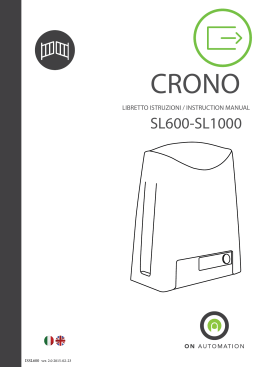
GATES
REA
LIBRETTO ISTRUZIONI / INSTRUCTION MANUAL
VIDEO DOORS
MOVING SYSTEMS
SAFETY SYSTEMS
ISSW250 ver. 1.1 2014-07-01
SW250-SW350
LIBRETTO ISTRUZIONI - INSTRUCTION MANUAL
GATES
SCOPO DEL MANUALE: questo manuale è stato redatto dal costruttore ed è parte integrante del prodotto. In esso sono contenute
tutte le informazioni necessarie per:
• la corretta sensibilizzazione degli installatori alle problematiche della sicurezza;
DOORS
•VIDEO
la corretta
installazione del dispositivo;
• la conoscenza approfondita del suo funzionamento e dei suoi limiti;
• il corretto uso in condizioni di sicurezza;
la costante osservanza delle indicazioni fornite in questo manuale, garantisce la sicurezza dell’uomo, l’economia di esercizio e una più
lunga durata di funzionamento del prodotto. Al fine di evitare manovre errate con il rischio di incidenti, è importante leggere attentaMOVING SYSTEMS
mente questo manuale, rispettando scrupolosamente le informazioni fornite. Le istruzioni, i disegni, le fotografie e la documentazione
contenuti nel presente manuale sono di proprietà di ON AUTOMATION s.r.l. e non possono essere riprodotti in alcun modo, né
integralmente, né parzialmente.
SCOPE OF THE MANUAL: this manual was prepared by the manufacturer and forms an integral part of the product. It provides all
SAFETY
SYSTEMS
the necessary
information on:
• the safety issues to be drawn to the attention of the installation technicians;
• correct installation of the device;
• operation and the limitations of the device, in detail;
• correct use in conditions of safety;
the instructions in this manual should be observed at all times in order to guarantee personal safety and the cost-effective operation
and long life-span of the product. It is important to have read and understood all the information provided in this manual on how to
ensure correct use and avoid the risk of accidents. The instructions, drawings, photographs and documentation in this manual are the
property of On Automation and must not be reproduced in any way, either in full or in part.
Leggenda dei simboli presenti nel manuale - Key of the symbols in this manual:
Questo simbolo evidenzia le parti del manuale da leggere con attenzione - This symbol draws attention to information to be read
with care
Questo simbolo evidenzia le parti del manuale riguardante la sicurezza - This symbol draws attention to information concerning
safety
Questo simbolo indica di prestare cautela - This symbol indicates the need for caution
Questo simbolo evidenzia la parte del manuale riguardante il cablaggio elettrico - This symbol draws attention to information
concerning the wiring
Questo simbolo indica la parte del manuale istruzione dedicato all’utente - This symbol indicates the section in the manual intended for the user
Questo simbolo indica il capitolo riguardante la manutenzione - This symbol indicates the chapter on maintenance
PREMESSA AL MANUALE ISTRUZIONI: nel corso delle operazioni di assemblaggio e montaggio e collaudo dell’ automatismo si possono verificare situazioni di pericolo se non si osservano le avvertenze di sicurezza contenute nelle istruzioni. Prima di procedere
leggere attentamente il presente manuale istruzioni. Rendere disponibili le istruzioni presso l’impianto per ogni necessità di utilizzo e manutenzione. I dati riportati sono da ritenersi puramente indicativi. Il costruttore declina ogni responsabilità per le possibili inesattezze contenute nel
presente manuale derivanti da errori di stampa o di trascrizione. L’azienda si riserva il diritto di apportare modifiche atte a migliorare il prodotto
senza preavviso.
FOREWORD TO THE INSTRUCTION MANUAL: the safety warnings must be observed in order to avoid danger during
assembly, mounting and testing of the automation device. Read this instruction manual with care before all else. Keep the instructions available
nearby for reference during all use and maintenance. The data are purely indicative. The manufacturer cannot assume responsibility for inaccuracies in this manual attributable to printing or transcription errors. The company reserves the right to make changes in light of improvements to
the product, without prior notice.
AVVERTENZE: leggere attentamente le istruzioni prima di iniziare l’installazione del prodotto.
I materiali dell’imballaggio (plastica, polistirolo, ecc.) non vanno dispersi nell’ambiente e non devono essere lasciati alla portata
dei bambini in quanto potenziali fonti di pericolo. La non corretta installazione dell’apparecchiatura può provocare gravi pericoli,
seguire attentamente tutte le istruzioni per l’installazione. Si raccomanda di lavorare nel pieno rispetto delle norme di sicurezza;
di operare in ambiente sufficientemente illuminato e idoneo per la salute; di indossare indumenti di protezione a norma di legge
(scarpe antinfortunistiche, occhiali di protezione, guanti ed elmetto) evitando di indossare articoli di abbigliamento che possano
impigliarsi. Adottare misure di protezione adeguate al rischio di ferita dovuto a schegge acuminate e ai possibili rischi di schiacciamento, urto e cesoiamento. Si raccomanda di osservare rigorosamente le norme nazionali valide per la sicurezza nei cantieri
(in italia d. lgs. 528/99 coordinato con d. lgs. 494/96 “attuazione della direttiva 92/57/ cee concernente le prescrizioni minime di
sicurezza e di salute da adottare nei cantieri temporanei o mobili”).Delimitare il cantiere per impedire il transito a persone non
autorizzate e non lasciare incustodita la zona di lavoro. Installazione, collegamenti elettrici e regolazioni devono essere effettuati
nell’osservanza della buona tecnica e in ottemperanza alle norme vigenti nel paese di installazione.
1
LIBRETTO ISTRUZIONI - INSTRUCTION MANUAL
Il costruttore della motorizzazione non è responsabile dell’inosservanza della buona tecnica nella costruzione della struttura da motorizzare, né delle deformazioni che dovessero intervenire nell’utilizzo. Un’ errata installazione può essere fonte di pericolo. Eseguire
gli interventi come specificato dal costruttore. Prima di iniziare l’installazione, verificare l’integrità del prodotto. Se il cavo di alimentazione è danneggiato, esso deve essere sostituito dal costruttore o dal suo servizio assistenza
tecnica o comunque da una persona con qualifica similare, in modo da prevenire ogni rischio. Verificare che la struttura esistente
abbia i necessari requisiti di robustezza e stabilità e che risponda alle normative di settore vigenti. L’installazione, il collaudo e la
messa in funzione della chiusura pedonale, così come le verifiche periodiche e gli interventi di manutenzione, possono essere eseguiti
soltanto da tecnici specializzati e formati sul prodotto.
WARNINGS: read the instructions with care before installing the product.
Do not dispose of the packaging (plastic, polystyrene, etc.) in the environment and do not leave it within reach of children because it
can be a source of danger. Incorrect installation of the device can also pose serious danger: follow all the instructions on installation
with care. It is recommended to observe all the safety standards in force; to work in a well lit environment where there are no health
risks; and to wear compliant protective equipment (safety footwear, protective glasses, gloves and hard hat) and close-fitting clothing.
Adopt measures to protect against flying parts and the potential risks of crushing, impact and cutting. It is recommended to observe
all domestic standards in force on safety on construction sites (in Italy, Legislative Decree 528/99 coordinated with Legislative Decree
494/96 “implementation of European directive 92/57/EEC concerning the minimum health and safety requirements to be adopted at
temporary or mobile construction sites”). Cordon off the site to prevent unauthorised access and do not leave the work area unattended. Installation, electrical connections and adjustments must be carried out in accordance with the code of good practice and
the domestic laws in force. The manufacturer of the motor unit cannot be held liable for poor construction of the structure to be
motorised, or for damage caused during use. Incorrect installation can be a source of danger. Follow the manufacturer’s instructions.
Before starting installation, check the condition of the product. If the power cord is damaged, it must be replaced by the manufacturer or its technical support service or, in any case, by a person with similar qualifications in order to prevent any risks.Check that the
structure on which it is to be installed is adequately sturdy and stable and complies with the applicable regulations in force. Installa-
tion, testing and commissioning of the unit, and all periodic checks and maintenance work must be entrusted to specialist technicians
trained in use of the product.
Indice-Index:
1- Descrizione generale - General description
2- Limiti di utilizzo - Limitations of use
3- Dati tecnici - Technical data
4- Dimensioni meccaniche - Mechanical dimensions
5- Quote di installazione - Installation heights
6- Predisposizione impianto - System preparation
7- Descrizione installazione - Installation description
8- Cablaggi elettrici - Electrical wiring
9- Sblocco manuale - Manual release
10- Manutenzione - Maintenance
11- Manuale utente - User manual
12 - Registro manutenzione e composizione impianto - Maintenance registry and system composition
13- Dichiarazione di conformità- Declaration of conformity
1
DESCRIZIONE GENERALE: motoriduttore elettromeccanico progettato per automatizzare cancelli battenti
di tipo residenziale. Il motoriduttore è irreversibile e mantiene il blocco in chiusura ed apertura solo per ante
di lunghezza superiore ai 2,5 metri si consiglia l’installazione dell’ elettroserratura. Il motoriduttore è privo di
frizione meccanica per questo motivo essere comandato da una centrale di comando dotata di regolazione di
coppia. Il serie di motoriduttori REA è presente nelle versioni DESTRO e/o SINISTRO a seconda dell’anta a
cui deve essere applicato, le ante devono essere guardate dall’interno. La scenta del motoriduttore da installare
và fatta valutando il peso e la lunghezza dell’anta su cui si intende installare ( vedi limiti di utilizzo). Prima di
iniziare l’installazione è necessario controllare la robustezza della struttura ( colonne cardini e fermi meccanici) nel caso nel cancello i fermi meccanici non siano presenti o danneggiati e necessario installarli, sia in
apertura che in chiusura.
2
LIBRETTO ISTRUZIONI - INSTRUCTION MANUAL
GATES
GENERAL
DESCRIPTION: electro-mechanical geared motor designed to automate residential-type hinged
gates. The geared motor is irreversible and keeps the gate locked during opening and closing. The installation of
an electric lock is recommended only for leaves exceeding 2.5 metres. The geared motor does not have a mechanical clutch. For this reason, it must be controlled by a control unit with torque adjustment.
VIDEO DOORS
The REA series geared motors are available in the RIGHT and/or LEFT version depending on the leaf on which
it is applied. The leaves must be looked at from the inside.
When choosing the geared motor to be installed, the weight and length of the leaf on which it is installed must
be assessed (see limitations of use).
MOVING SYSTEMS
Before starting installation, check the sturdiness of the structure (hinged columns and mechanical stops). The
mechanical stops need to be installed on the opening and closing if the gate does not have mechanical stops or if
these are damaged.
2
SAFETY SYSTEMS
LIMITI DI UTILIZZO - LIMITATIONS OF USE:
MODELLO
MODEL
SW250
SW250
SW350
SW350
SW350
LUNGHEZZA (metri)
LENGTH (metres)
2
2,5
2,5
3
3,5
PESO (Kg)
WEIGHT (kg)
350
300
350
300
250
3
CARATTERISTICHE TECNICHE - TECHNICAL CHARACTERISTICS:
Modello
Grado di
protezione
Model
Protection Weight
rating
(kg)
SW250 IP44
SW350 IP44
Peso
(Kg)
6
8
Alimentazione
Assorbimento
Power
supply
Current Power
230VAC 1,2A
230VAC 1,2A
Potenza
Intermitten- Spinta
za di lavoro
Tempo di
apertura
Condensatore Temperatura
di esercizio
Duty cycle Push
Travel
time
Capacitor
Temperature
range
8UF
8UF
-20/+55°C
-20/+55°C
280W 40%
280W 40%
3200N 23 sec.
3200N 34 sec.
4
DIMENSIONI MECCANICHE - MECHANICAL DIMENSIONS:
00 mm
SW250 = 4
00 mm
6
SW350 =
170 mm
30 mm
SW250 = 7
30 mm
SW350 = 9
83 mm
3
Figura 1
Figure 1
LIBRETTO ISTRUZIONI - INSTRUCTION MANUAL
5
QUOTE DI INSTALLAZIONE - INSTALLATION HEIGHT:
X
Y
Figura 2
Figure 2
Modello Apertura Tempo di apertura
Model Opening
Opening time
SW250
90°
23 sec.
SW250
115°
23 sec.
SW350
90°
34 sec.
SW350
115°
34 sec.
Lunghezza anta
Leaf length
2,5 m
2m
3,5 m
3m
X
Y
180 mm
180 mm
280 mm
280 mm
180 mm
150 mm
280 mm
240 mm
N.B.: nella tabella vengono indicate le quote ottimali, con il valore di X uguale a Y si ha una velocità costante su
tutta la corsa del cancello. La somma della quota X e Y non deve mai superare la corsa massima utile del motoriduttore (360 mm per SW250 e 560 mm per SW350).
Note: the optimal heights are reported in the table. When the X value is equal to the Y value, there is a constant
speed on the entire stroke of the gate. The sum of height X and Y must never exceed the maximum stroke allowed for the geared motor (360 mm for SW250 and 560 mm for SW350).
6
PREDISPOSIZIONE IMPIANTO - SYSTEM PREPARATION:
3
1
4
2
3
6
5
8
4
Figura 3
Figure 3
7
9
5
7
6
4
LIBRETTO ISTRUZIONI - INSTRUCTION MANUAL
GATES
Numero
Number
Descrizione
Description
Tipo cavo
Type of wire
1
Lampeggiante con antenna - Beacon with antenna
2x1mmq + RG58 / 2x1mm2 + RG58 ( lunghezza massima consigliata 5 metri - maximum recommended length 5 metres)
2
Selettore a chiave - Key selector
3x1mmq / 3x1mm2
3
Fotocellule esterne - External photocells
TX: 2x1mmq - RX : 4x1mmq / TX: 2x1mm2 - RX : 4x1mm2
4
VIDEO DOORS
Motoriduttore - Geared motor
4x1,5mmq / 4x1.5mm2
MOVING SYSTEMS
5
Pozzetti per tubazioni - Sumps for pipes
-
6
Fotocellule interne - Internal photocells
TX: 2x1mmq - RX : 4x1mmq / TX: 2x1mm2 - RX : 4x1mm2
7
Fermi meccanici in apertura - Mechanical stops for
opening
-
Centrale di comando - Control unit
-
SAFETY SYSTEMS
8
9
Linea alimentazione - Power line
3x1,5 mmq / 3x1.5 mm2
Non è possibile eseguire giunzioni nei pozzetti e i cavi di entrata nel contenitore della centrale di comando devono essere inseriti
utilizzando appositi pressavi per mantenere il grado IP del contenitore.
Splicing cannot be done in the sumps and the wires entering the container of the control unit must be inserted using approved
cable glands in keeping with the IP protection of the container.
7
DESCRIZIONE INSTALLAZIONE - INSTALLATION DESCRIPTION
Figura 4
Figure 4
1- Portare il cancello in posizione di completa chiusura
2- Fissare la staffa a colonna prestando attenzione al rispetto delle quote di installazione
3- Inserire il motoriduttore nella staffa, portare il stelo alla massima estensione per poi farlo rientrare di 2 cm
4- Controllare tramite la livella l’asse orizzontale
5- Eseguire 2 fori per il fissaggio della staffa di trascinamento anta ( si consiglia di inserire delle viti con diametro 8 mm con una lunghezza tale che permetta l’attraversamento dello spessore del cancello)
1- Completely close the gate
2- Fix the bracket to the column; make sure installation heights are respected
3- Insert the geared motor into the bracket; fully extend the rod and then bring it back by 2 cm
4- Check the horizontal axis using the level
5- Make 2 holes to fix the leaf advance bracket (it is recommended that screws with an 8 mm diameter and
length be inserted to enable traversing of the gate thickness)
5
LIBRETTO ISTRUZIONI - INSTRUCTION MANUAL
Figura 5 Figura 6
Figure 5 Figure 6
Lubrificare tutti i perni anteriori e posteriori, installare il motoriduttore prestando attenzione di inserire la rondella tra la staffa e forcella, serrare la vite tramite il dado evitando di stringere troppo per evitare attriti durante il
movimento.
Lubricate all front and rear pins, install the geared motors being careful to insert the washer between the bracket
and fork, tighten the screws without over tightening to avoid friction during motion.
8
CABLAGGI ELETTRICI- ELECTRICAL WIRING:
SX
Condensatore
Capacitor
Nero - Black
MOT.
Apre - Open
Grigio - Gray Comune - Common
Marrone - Brown
Chiude - Close
Giallo - Verde Yellow - Green
Marrone - Brown
DX
Grigio - Gray
Condensatore
Capacitor
MOT.
Nero - Black
Giallo - Verde Yellow - Green
Figura 7
Figure 7
Collegare il condensatore in parallelo tra apre e chiude del motore elettrico, nel caso la distanza tra la centrale
di comando e il motore elettrico superi i 10 metri di consiglia di eseguire il collegamento del condensatore nella
scatola di derivazione vicino al motoriduttore (il motoriduttore viene fornito con un cavo di 1 metro).
Connect the capacitor in parallel between the opening and closing of the electric motor; it is advisable to connect
the capacitor in the junction box near the motor if the distance between the control unit and the electric motor
exceeds 10 meters (the motor is supplied with a 1-meter cable).
SBLOCCO MANUALE - MANUAL RELEASE
9
Inserire la chiave data in dotazione e girare di 90° in
senso orario per sbloccare manualmente, per ripristinare il funzionamento automatico girare la chiave in
senso antiorario di 90°.
Insert the key supplied and turn 90° clockwise to unlock it manually; to reset automatic operation, turn
the key 90° counter clockwise.
BLOCCATO
LOCK
SBLOCCATO
UNLOCK
Figura 8
Figure 8
6
LIBRETTO ISTRUZIONI - INSTRUCTION MANUAL
GATES
10
MANUTENZIONE - MAINTENANCE :
Si consiglia si eseguire la manutenzione ogni 12 mesi controllando:
- tenuta meccanica del sistema sostegno anta e dei fermi meccanici
VIDEO DOORS
- lubrificazione dei perni di fissaggio del motoriduttore
- controllare assenza di attriti sul movimento dell’anta
- la funzionalità del sistema di sblocco manuale
- controllare le viti di fissaggio delle staffe
MOVING SYSTEMS
- verificare l’integrità dei cavi di alimentazione del motoriduttore.
It is recommended that maintenance be carried out every 12 months. During maintenance, check:
- the mechanical seal of the system supporting the leaf and mechanical stops
- the lubrication of the geared motor securing pins
SAFETY SYSTEMS
- the absence of friction on leaf motion
- the functioning of the manual release system
- the bracket fixing screws
- the integrity of the geared motor power cables
11
MANUALE UTENTE - USER MANUAL:
Le istruzioni fornite sono parte integrale ed essenziale del prodotto e devono essere lette attentamente, poiché
contengono importanti avvertimenti per l’uso e la manutenzione. Queste istruzioni devono essere conservate
e consegnate a tutti i futuri possibili utilizzatori. Il motoriduttore SW250 - 350 è progettato per movimentare
cancelli battenti. È vietato utilizzare il prodotto per scopi diversi da quelli previsti o impropri. Ogni altro utilizzo
è improprio e quindi pericoloso. È vietato manomettere o modificare il prodotto. Non permettere ai bambini
di giocare o sostare nel raggio d’azione dell’automazione. Tenere sotto controllo i dispositivi di attivazione del
movimento in modo da evitare azionamenti involontari da parte di bambini o estranei.L’automazione può essere
comandata di età non inferiore a 8 anni e da persone con ridotte capacità fisiche, sensoriali o mentali, o della
necessaria conoscenza, purché sotto sorveglianza oppure dopo che le stesse abbiano ricevuto istruzioni relative
all’uso sicuro dell’automazioni e alla comprensione dei pericoli ad esso inerenti. I bambini non devono giocare
con l’automazione. La pulizia e la manutenzione destinata ad essere effettuata dall’ utilizzatore non deve essere
effettuata da bambini senza sorveglianza . I bambini sotto sorveglianza non devono giocare con l’ automazione.
Si raccomanda di consultare la ditta installatrice dell’automazione e stabilire un piano di manutenzione programmata, come richiesto dalle normative di settore (per i Paesi CEE: Direttiva Macchine 2006/42/CEE). Far eseguire
periodicamente una corretta manutenzione, in base al libretto di manutenzione rilasciato dall’installatore.
Il collegamento, il collaudo e la messa in funzione, così come le verifiche periodiche e gli interventi di manutenzione, inclusa la pulizia dell’azionamento, possono essere eseguiti soltanto da tecnici specializzati e formati sul
prodotto. Esaminare frequentemente la movimentazione, verificare l’ eventuale presenza di segni di usura o danneggiamento dei cavi, in questo caso o in caso di guasto o di funzionamento non regolare, togliere alimentazione
all’automazione azionando l’interruttore principale. Non tentare di intervenire o di riparare l’unità principale e
contattare chi ha installato l’automazione o un altro installatore specializzato. Non rispettare questo avvertimento
può portare a situazioni di pericolo. All’utilizzatore non è consentito intervenire sull’impianto e sull’apparecchiatura di controllo, né operare all’interno del box elettrico. In caso di guasti o di mancanza di energia elettrica è
possibile attivare lo SBLOCCO MANUALE seguendo la seguente procedura:
- inserire la chiave di sblocco data in dotazione nella sede laterale del motoriduttore
- girare la chiave in senso orario di 90°, il cancello può muoversi manualmente.
Per ritornare al funzionamento automatico ripetere la procedura descritta girando la chiave in senso antiorario
di 90°, vedi figura 9.
L’ azionamento dello sblocco manuale può causare il movimento incontrollato della parte guidata a causa della
meccanica, guasti o una condizione di disequilibrio, per questo motivo si consiglia dopo avere azionato lo sblocco manuale di portare il cancello in posizione di completa apertura e ripristinare lo sblocco manuale.
7
LIBRETTO ISTRUZIONI - INSTRUCTION MANUAL
The user manual provided is an integral part of the product and must be read with care, as it contains important instructions on use and maintenance. This manual must be kept and made available to other future users.
The SW250 - 350 geared motor is designed for the motion of hinged gates. It is forbidden to use the product for
purposes other than those specified or for improper purposes. Any other use is considered improper and potentially dangerous. It is forbidden to tamper with or make changes to the product. Do not allow children to play or
stand within the operating radius of the automation. Keep the motion activation devices under control in order
to prevent involuntary activation by children or other people. The automation can be controlled by people who
are 8 years old and older and by people with reduced physical, sensory or mental capabilities, or the necessary
knowledge provided that they are supervised or have received instructions regarding the safe use of the automation and understand the inherent dangers. Children must not play with the automation. The cleaning and maintenance to be carried out by the user must not be done by children without supervision. Supervised children
must not play with the automation. It is recommended to contact the installation company and prepare a routine
maintenance schedule, as required in accordance with the applicable standards (within the EEC: Machine Directive 2006/42/EEC). Perform correct routine maintenance referring to the maintenance booklet provided by the
installer.
The connection, testing and commissioning of the system, and all periodic checks and maintenance work,
including cleaning of the drive, must be entrusted to specialist technicians trained in the use of the product.
Frequently check the motion, verify any signs of use or damage of the cables, in this case or in case of failure or
irregular operation, turn off the power to the automation at the main switch. Do not attempt to make changes or
repair the main system; for these purposes, contact the person who installed the automation, or another specialist installer. Failure to observe this requirement can be dangerous. The user is not permitted to either service the
system and control equipment, or access the electrical box. In the event of a malfunction or power failure, it is
possible to activate the MANUAL RELEASE as follows:
- insert the supplied release key in the side seat of the geared motor
- turn the key 90° clockwise, the gate can move manually.
To return to automatic operation, repeat the procedure described above by turning the key 90° counter clockwise (see figure 9).
Actuation of the manual release can cause uncontrolled movement of the driven part due to the mechanical parts, failure or a state of imbalance. Therefore, it is recommended to fully open the gate and to restore the
manual release after actuation.
BLOCCATO
LOCK
SBLOCCATO
UNLOCK
FIGURA 9
FIGURE 9
8
LIBRETTO ISTRUZIONI - INSTRUCTION MANUAL
12
GATES
REGISTRO MANUTENZIONE - MAINTENANCE REGISTER:
VIDEO DOORS
DATA
DATE
MOVING SYSTEMS
MANUTENZIONE MANUTENZIONE
ORDINARIA
STRAORDINARIA
ORDINARY
EXTRAORDINARY
MAINTENANCE
MAINTENANCE
DESCRIZIONE INTERVENTO
WORK DESCRIPTION
SAFETY SYSTEMS
9
PARTI
SOSTITUITE
PARTS
REPLACED
FIRMA
SIGNATURE
LIBRETTO ISTRUZIONI - INSTRUCTION MANUAL
COMPOSIZIONE IMPIANTO - SYSTEM COMPOSITION:
CODICE
CODE
DESCRIZIONE
DESCRIPTION
QUANTITÀ
QUANTITY
NOTE E PARTICOLARI DELL’ IMPIANTO - NOTES AND SYSTEM PARTS:
10
DICHIARAZIONE CE CONFORMITÀ
SW250 e SW350 - Motoriduttore per cancelli battenti 230VAC è conforme alle seguenti disposizioni pertinenti:
89/336/CEE, 93/68/CEE
CE DECLARATION OF CONFORMITY
SW250 and SW350 - The geared motor for 230VAC hinged gates conforms to the following standards:
ISSW250 ver. 1.1 2014-07-01
LIES WI
T
MP
O
H
C
89/336/EEC, 93/68/EEC
Via Antonio Ferrero, 9 - Padova 35133 - Italy
Tel: +39 049 8876545
E-mail: [email protected] - www.onautomation.com
Scarica