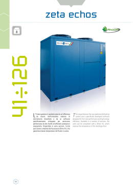
technical catalogue
zeta echos fc
44÷144 KW
Air/water chiller with integrated
free-cooling
> ZETA ECHOS FC
Water chiller
> ZETA ECHOS FC /LN
Low noise version
> ZETA ECHOS FC /NG
No glycol unit
> ZETA ECHOS FC /ST
Water chiller with storage tank and pumps
4
Technical Catalogue Zeta Echos FC
Technical characteristics
Technical data standard unit
Electrical data standard unit
ZETA ECHOS FC - Cooling capacIty
Operating limits
Sound level
Overall dimensions, weights,
clearances and hydraulic connections
06
10
12
13
15
16
17
Installations recommendations
25
Zeta Echos Fc
index
5
TECHNICAL CHARACTERISTICS
ZETA ECHOS FC
Air-cooled water chiller with free-cooling, hermetic scroll
compressors and plate evaporators.
The features of the standard units are as follows:
UNIT FRAME
Self-supporting frame with removable panels clad with
expanded polyurethane sound-absorbing matting, made of
galvanised sheet steel with 180°C baked-on polyester powder
coating (Colour RAL 5014) to provide a durable weatherproof
finish. Threaded fasteners in stainless steel.
COMPRESSORS
Hermetic type orbital scroll compressors connected in parallel,
equipped with an oil level sight glass, thermal protection by
means of an internal Klixon cut-out and oil equalisation line.
The compressors, which are housed in a sound insulated
compartment and separated from the air flow, are accessible
by removing specific panels that allow maintenance work to
be carried out while the system is running.
CONDENSERS
Composed of a high efficiency coil with staggered pattern
rows of copper tubes and aluminium fins.
The finned core is protected by a grille with metal mesh filter
supplied as standard.
FREE COOLING
Made up from an interpenetrating coil with rows with copper
pipes and high-efficiency aluminium fins.
The finned core is protected by a grille with metal mesh filter
supplied as standard.
A unique ventilating section cools the condensing coil and the
free-cooling coil, which are positioned in parallel on opposite
sides of the unit. The air flow is managed automatically by
a microprocessor that controls the opening of motorised
shutters positioned facing the coils and regulates the rotation
speed of the fans. When the conditions make it suitable, the
free-cooler shutter is opened, the fans
are made to turn at maximum speed and condensation is
controlled by modulating the opening of the condenser
shutter. Otherwise, the free-cooler shutter remains closed,
that of the condenser completely open and condensation is
controlled by regulating the rotation speed of the fans.
FANS
Axial fans with rev. regulator for slave application, designed
to optimise efficiency and reduce noise emissions, directly
coupled to a 6-pole motor with internal Klixon overload
protection. Motor protection rating is IP 54. The fan is
equipped with a safety grille in compliance with UNI EN 294.
EVAPORATOR
Stainless steel 316 AISI brazed plate exchanger, thermally
insulated by means of a jacket in closed cell expanded
material.
Each evaporator is equipped with a freeze protection
temperature probe and each unit is equipped with a
mechanical flow switch as part of the standard outfit.
The use of plate type heat exchangers makes for:
• Improved COP/EER;
• Reduced refrigerant charge in the circuit;
6
Technical Catalogue Zeta Echos FC
• Reduced unit weight and dimensions;
• Easier maintenance.
REFRIGERANT CIRCUIT
The refrigerant circuit includes: liquid line shut-off valve, charge
connection, liquid line sight glass, filter dryer, thermostatic
expansion valve with external pressure equalisation, high and
low pressure switches, and relief valve.
The high and low pressure values and relative condensing
and evaporating temperature values are detected by means
of pressure transducers which enable the relative data to be
read on the controller display. Note that the high pressure
side is anyway equipped with high pressure switches and
relief valves.
Electrical power supply [V/f/Hz]: 400/3N~/50 ±5% modelli da 3.2 a 10.2,
400/3~/50 ±5% models from 12.2 to 13.2.
CONTROLS AND SAFETY DEVICES
• chilled water temperature probe (at evaporator inlet);
• inlet water temperature control probe
• room air temperature control probe
• freeze protection probe at the outlet of each evaporator;
• high pressure switch with manual reset;
• safety low pressure switch with manual reset managed by controller;
• high pressure relief valve;
• compressor overtemperature protection;
• fans overtemperature protection;
• mechanical flow switch supplied as part of the standard outfit for models
from 3.2 to 13.2
Zeta Echos Fc
ELECTRICAL PANEL
The electrical panel includes:
• Main circuit breaker;
• Fuses to protect control and power circuits;
• Circuit breakers for pumps (if present);
• Compressor contactors;
• Fan contactors;
• Pump contactors (ST version);
• Microprocessor to control the following functions:
- Water temperature regulation with measurement of inlet temperature;
- Freeze protection;
- Compressor time intervals;
- Compressor start sequence and automatic lead/lag selection;
- Alarm signalling;
- Alarm reset;
- Capacity control;
- Cumulative potential-free contact for remote alarm;
- Forcing of capacity step control due to arrival at pressure limit;
- Alarm history;
• Display presentation of the following information:
- Inlet and outlet water temperature;
- Programmed temperature set-point and differentials;
- Alarm description;
- Compressor operating hours count;
- number of starts of unit and compressors;
- high and low pressure values and relative condensing and evaporating temperature values;
- black box function;
TESTING
The units are subjected to a factory test and supplied complete with oil and
refrigerant.
7
VERSIONS
HYDRAULIC MODULE OPTIONS
ZETA ECHOS FC /ST 2PS:
Unit with storage tank and pumps
In addition to the components featured on ZETA ECHOS FC,
this model includes:
• insulated storage tank;
• two water pumps, one of which in stand-by with
automatic changeover in case of faults;
• expansion vessel;
• check valves;
• gate valves.
Version ST is available in a further four configurations:
ST 1PS: with one pump and tank;
ST 1P:
with one pump and without tank;
ST 2P:
with 2 pumps without tank;
ST S:
with tank without pumps.
ACCESSORY VERSIONS
ZETA ECHOS FC /LN:
Low noise unit.
As well as the components of the basic version, the unit also
envisions the compressors compartment which is completely
noise insulated using sound-absorbant and sound-proof
materials.
ZETA ECHOS FC /NG:
No glycol unit
As well as the components of the basic version, the unit,
envisions a further water-water heat exchanger that allows
to confine the mixture of water and glycol in a closed circuit
inside the machine. Once the mixture is cooled, it is sent to
the above-mentioned heat exchanger where it absorbs heat
from the water coming from the utilities circuit.
8
Technical Catalogue Zeta Echos FC
ACCESSORIES
REFRIGERANT CIRCUIT ACCESSORIES
• Electronic thermostatic valve;
• High and low pressure manometers
• Liquid receivers;
• Suction and discharge valves on the compressors common line;
• Kit for low water temperatures.
ELECTRICAL ACCESSORIES
• EC fans;
• RS 485 serial interface supporting Carel, Modbus;
• Power factor correction cosφ≥0.9 at nominal operating conditions; on the IP
55 unit exterior panel (electrical power supply to be provided by the installer
directly from the main power line). The accessory is combined with volt-free
contacts for unit operating status;
• Remote user terminal panel (in addition to the standard terminal);
• Individual voltage/free functioning contacts
(compressor, fan and pump if installed)
• Water outlet temperature control;
• Set-point modification with remote signal (0-1V, 0-10V, 0-20mA, 4-20mA);
- RS 485 serial interface supporting Carel, Modbus;
- Echelon and Bacnet, combinable also with Johnson and Trend supervision;
• Soft starter: to restrict compressor peak current.
• Inverter for management of the FC water coil side pump
(only for NG version)
MISCELLANEOUS ACCESSORIES
• Rubber anti-vibration mounts;
• Pre-painted aluminium condensing coil;
• Condensing coil with passivation treatment of aluminium and polyurethane
based top coat. The treatment is composed of two coats, the first of which is
an aluminium passivating primer while the second is a polyurethane-based
top coat. The product features excellent corrosion resistance and is able
to withstand almost all adverse weather and atmospheric conditions. For
installations in coastal environments subject to salt spray, rural or industrial
area and cities;
• Pre-assembled execution;
• Timber crate packing;
• Pallet/skid for container shipment;
• Non-standard “RAL” paint colours.
Zeta Echos Fc
HYDRAULIC CIRCUIT ACCESSORIES
• 3.way modulating valve (not available in the NG version).
9
technical data
Unit size
Cooling
Nominal cooling capacity
Total power input for cooling
EER
ESEER
Free-Cooling
Nominal cooling capacity
Pressure drop on free-cooling coil
TFT - Total Free-cooling Temperature
3.2
4.2
5.2
6.2
7.2
kW
kW
45,1
13,0
3,48
4,67
50,7
15,0
3,37
4,53
58,0
17,8
3,27
4,37
68,2
19,3
3,54
4,65
75,3
23,4
3,23
4,37
kW
kPa
°C
31,0
11,4
0,7
32,9
14,7
-0,4
34,5
18,6
-1,9
44,9
21,2
-0,2
46,0
25,3
-1,4
3.2
4.2
5.2
6.2
7.2
kW
kW
46,0
13,0
3,53
4,67
51,7
15,1
3,41
4,53
59,1
17,9
3,31
4,37
69,4
19,4
3,58
4,65
76,6
23,5
3,26
4,37
(3)
kW
kPa
°C
21,7
31,2
-2,7
23,0
32,0
-3,7
23,8
34,0
-5,0
31,0
14,5
-3,4
31,9
15,2
-4,5
(3)
kW
kPa
°C
2/1
0-50-100
5,2
9,0
2/1
0-50-100
6,5
9,0
Scroll
2/1
0-50-100
6,5
10,5
2/1
0-50-100
6,5
16,0
2/1
0-50-100
6,6
16,0
n°
m3/h
2
17.427
2
17.427
Axial
2
16.023
2
19.513
2
19.513
n°
l/h
kPa
1
8.610
69,1
1
9.690
66,8
Plates
1
11.110
61,6
1
13.030
45,5
1
14.420
55,0
kPa
kPa
l
l
171
160
165
18
160
146
165
18
145
128
165
18
174
154
200
18
148
124
200
18
dB(A)
dB(A)
dB(A)
dB(A)
83
55
81
53
83
55
81
53
85
57
81
53
85
57
81
53
85
57
82
54
mm
mm
mm
kg
2590
1337
1400
921
2590
1337
1400
927
2590
1337
1400
959
3250
1334
1740
1168
3250
1334
1740
1182
(1)
(1),(2)
(1)
(3)
ZETA ECHOS FC / NG
Unit size
Cooling
Nominal cooling capacity
Total power input for cooling
EER
ESEER
Free-Cooling
Nominal cooling capacity
Pressure drop on free-cooling coil
TFT - Total Free-cooling Temperature
Compressors
Type
Quantity / Circuits
Capacity steps
Total oil charge
Total refrigerant charge
Fans
Type
Quantity
Air flow
Evaporator
Type
Quantity
Water flow
Pressure drop
Hydraulic module
External available pressure
External available pressure
Tank capacity
Expansione vassel
Sound level
Sound power value (standard unit)
Sound pressure value (standard unit)
Sound power value (LN version)
Sound pressure value (LN version)
Basic unit size and weights
Length
Width
Height
Operating weigh
(1)
(2)
(3)
(4)
10
(1)
(1),(2)
(1)
(6),(7)
(6),(8)
(6)
(4)
(5)
(4)
(5)
Ambient air temperature 30°C; evaporator inlet/outlet water temperature 10-15 °C
Total power input is sum of compressors and funs power input
Ambient air temperature 5°C; evaporator inlet fluid temperature 15 °C; Glycol at 30%
Sound power values calculate in compliance with ISO 3744
(5)
(6)
(7)
(8)
Sound pressure values measured at 10 meters from the unit in free field conditions and directional factor Q=2
ST 2PS version
With free-cooling inactive
With free-cooling active
technical data
Unit size
Cooling
Nominal cooling capacity
Total power input for cooling
EER
ESEER
Free-Cooling
Nominal cooling capacity
Pressure drop on free-cooling coil
TFT - Total Free-cooling Temperature
8.2
9.2
10.2
12.2
13.2
kW
kW
89,7
24,8
3,62
4,99
102,6
30,3
3,39
4,63
113,9
36,3
3,14
4,37
132,3
41,6
3,18
4,45
144,4
47,9
3,01
4,26
kW
kPa
°C
65,0
23,0
1,2
66,7
29,2
-0,4
67,8
35,1
-1,7
81,7
45,6
-1,2
82,8
53,3
-2,4
8.2
9.2
10.2
12.2
13.2
kW
kW
91,4
24,9
3,67
4,99
104,5
30,4
3,43
4,63
115,9
36,5
3,17
4,37
134,7
41,8
3,22
4,45
147,0
48,2
3,05
4,26
(3)
kW
kPa
°C
45,0
17,1
-2,0
46,2
17,3
-3,6
47,1
18,2
-4,8
56,7
21,3
-4,5
57,5
22,6
-5,5
(3)
kW
kPa
°C
2/1
0-50-100
6,2
24,0
2/1
0-50-100
12,4
24,0
Scroll
2/1
0-50-100
12,4
24,0
2/1
0-50-100
12,4
24,0
2/1
0-50-100
14,2
24,0
n°
m3/h
3
29.089
3
29.089
Axial
3
29.089
2
40.087
2
40.087
n°
l/h
kPa
1
17.130
62,9
1
19.610
61,5
Plates
1
21.800
64,8
1
25.290
69,0
1
27.630
67,4
kPa
kPa
l
l
191
168
200
18
174
145
200
18
190
156
200
18
165
120
200
18
151
98
200
18
dB(A)
dB(A)
dB(A)
dB(A)
85
57
83
55
86
58
84
56
86
58
84
56
87
59
85
57
87
59
85
57
mm
mm
mm
kg
4200
1434
1740
1524
4200
1434
1740
1538
4200
1434
1740
1546
4200
1434
1880
1650
4200
1434
1880
1690
(1)
(1),(2)
(1)
(3)
ZETA ECHOS FC / NG
Unit size
Cooling
Nominal cooling capacity
Total power input for cooling
EER
ESEER
Free-Cooling
Nominal cooling capacity
Pressure drop on free-cooling coil
TFT - Total Free-cooling Temperature
Compressors
Type
Quantity / Circuits
Capacity steps
Total oil charge
Total refrigerant charge
Fans
Type
Quantity
Air flow
Evaporator
Type
Quantity
Water flow
Pressure drop
Hydraulic module
External available pressure
External available pressure
Tank capacity
Expansione vassel
Sound level
Sound power value (standard unit)
Sound pressure value (standard unit)
Sound power value (LN version)
Sound pressure value (LN version)
Basic unit size and weights
Length
Width
Height
Operating weigh
(1)
(2)
(3)
(4)
(1)
(1),(2)
(1)
(6),(7)
(6),(8)
(6)
(4)
(5)
(4)
(5)
Ambient air temperature 30°C; evaporator inlet/outlet water temperature 10-15 °C
Total power input is sum of compressors and funs power input
Ambient air temperature 5°C; evaporator inlet fluid temperature 15 °C; Glycol at 30%
Sound power values calculate in compliance with ISO 3744
(5)
(6)
(7)
(8)
Sound pressure values measured at 10 meters from the unit in free field conditions and directional factor Q=2
ST 2PS version
With free-cooling inactive
With free-cooling active
11
general electrical data
Unit size
Maximum absorbed power
(1),(3)
kW
Full load current
(2),(3)
A
(4)
A
Maximum starting current
Fan motor nominal power
Fan motor nominal current
Pump motor nominal power
Pump motor nominal current
Power supply
Control power supply
Control power supply
n° x kW
n° x A
kW
A
V/ph/Hz
V/ph/Hz
V/ph/Hz
Unit size
Maximum absorbed power
(1),(3)
kW
Full load current
(2),(3)
A
(4)
A
Maximum starting current
Fan motor nominal power
Fan motor nominal current
Pump motor nominal power
Pump motor nominal current
Power supply
Control power supply
Control power supply
(1)
(2)
(3)
(4)
12
n° x kW
n° x A
kW
A
V/ph/Hz
V/ph/Hz
V/ph/Hz
3.2
4.2
5.2
6.2
7.2
19,4
(21,7)
34,6
(39,4)
114
2 x 0,7
2 x 1,3
2,3
4,8
4
21,6
(23,9)
44,6
(49,4)
135
(140)
2 x 0,7
2 x 1,3
2,3
4,8
4
25,0
(27,3)
46,6
(51,4)
143
(148)
2 x 0,7
2 x 1,3
2,3
4,8
4
400/3N~/50 ±5%
230/1~/50 ±5%
27,8
(30,1)
52,6
(57,4)
146
(151)
2 x 0,7
2 x 1,3
2,3
4,8
4
34,4
(36,7)
72,6
(77,4)
196
(201)
2 x 0,7
2 x 1,3
2,3
4,8
4
8.2
9.2
10.2
12.2
13.2
39,1
(42,1)
81,9
(88,1)
238
(244)
3 x 0,7
3 x 1,3
3,0
6,2
4
46,2
(49,2)
93,9
(100,1)
258
(264)
3 x 0,7
3 x 1,3
3,0
6,2
4
53,3
(56,3)
105,9
(112,1)
270
(276)
3 x 0,7
3 x 1,3
3,0
6,2
4
400/3N~/50 ±5%
230/1~/50 ±5%
61,6
(64,6)
124,0
(130,2)
319
(325)
2 x 2,0
2 x 4,0
3,0
6,2
4
68,0
(71,0)
138,0
(144,2)
333
(339)
2 x 2,0
2 x 4,0
3,0
6,2
4
Mains power supply to allow unit operation
Maximum current before safety cut-outs stop the unit. This value is never exceeded and must be used to size the electrical supply cables and relevant safety devices
(refer to electrical wiring diagram supplied with the unit)
Values in brackets refer to ST version units (units with storage tank and pumps or units with exclusively pumps)
Maximum starting current calculated considering the bigger size compressor starting current plus the maximum absorbed power of the other electrical devices (pumps, fans)
ZETA ECHOS FC - Cooling capacIty
AMBIENT AIR TEMPERATURE [°C]
Model
3.2
4.2
5.2
6.2
7.2
Ta
[°C]
25
Pf
30
Pe
Pf
35
Pe
Pf
40
Pe
Pf
45
Pe
Pf
Pe
5
40,23
9,96
37,98
11,13
35,53
12,47
32,88
13,98
30,01
15,7
6
41,42
10,04
39,13
11,21
36,63
12,55
33,92
14,07
30,99
15,79
7
42,66
10,12
40,33
11,3
37,78
12,64
35,02
14,16
31,98
15,88
8
43,9
10,21
41,52
11,39
38,91
12,73
36,07
14,25
32,99
15,97
9
45,18
10,3
42,74
11,48
40,07
12,82
37,16
14,34
34,01
16,07
10
46,47
10,4
43,97
11,58
41,24
12,92
38,26
14,44
35,04
16,17
5
45,38
11,72
42,94
13,04
40,29
14,56
37,37
16,33
34,12
18,39
6
46,69
11,83
44,19
13,15
41,49
14,68
38,51
16,45
35,22
18,51
7
48,04
11,95
45,49
13,27
42,74
14,8
39,72
16,57
36,33
18,63
8
49,41
12,07
46,79
13,39
43,97
14,92
40,87
16,7
37,45
18,75
9
50,81
12,2
48,12
13,52
45,22
15,05
42,06
16,83
38,58
18,88
10
52,21
12,33
49,45
13,66
46,48
15,19
43,25
16,97
39,7
19,02
5
52,31
14
49,19
15,66
45,81
17,54
42,15
19,68
38,21
22,1
6
53,8
14,13
50,62
15,79
47,16
17,68
43,42
19,82
39,39
22,25
7
55,34
14,26
52,1
15,93
48,57
17,83
44,77
19,98
40,58
22,4
8
56,9
14,4
53,58
16,08
49,96
17,98
46,04
20,13
41,8
22,55
9
58,5
14,55
55,1
16,23
51,39
18,13
47,37
20,28
43,03
22,71
10
60,1
14,7
56,62
16,38
52,82
18,29
48,71
20,44
44,25
22,88
5
61,25
15,53
57,86
17,24
54,14
19,18
50,1
21,38
45,7
23,89
6
62,99
15,66
59,52
17,36
55,73
19,31
51,59
21,52
47,09
24,02
7
64,79
15,78
61,26
17,5
57,4
19,45
53,19
21,66
48,51
24,16
8
66,6
15,92
62,98
17,63
59,01
19,58
54,67
21,8
49,94
24,31
9
68,46
16,05
64,75
17,77
60,69
19,73
56,24
21,94
51,38
24,45
10
70,32
16,19
66,53
17,91
62,37
19,87
57,8
22,09
52,83
24,61
5
67,86
18,89
63,98
20,86
59,78
23,12
55,22
25,73
50,3
28,75
6
69,79
19,09
65,8
21,07
61,48
23,34
56,8
25,95
51,75
28,98
7
71,78
19,29
67,68
21,28
63,25
23,56
58,46
26,19
53,29
29,24
8
73,88
19,51
69,59
21,5
65,02
23,8
60,08
26,44
54,74
29,48
9
75,9
19,72
71,53
21,73
66,83
24,04
61,75
26,69
56,25
29,74
10
77,96
19,94
73,49
21,97
68,64
24,29
63,42
26,95
57,77
30,01
Ta: temperature of external air, dry bulb [°C]
Pf: cooling capacity [kW]
Pe: compressors power input [kW]
13
ZETA ECHOS FC - Cooling capacIty
AMBIENT AIR TEMPERATURE [°C]
Model
8.2
9.2
10.2
12.2
13.2
Ta
[°C]
25
Pf
35
Pe
Pf
40
Pe
Pf
45
Pf
Pe
5
79,74
19,87
75,38
21,96
70,82
24,31
65,98
26,99
60,84
30,02
6
82,07
20
77,68
22,09
73,01
24,46
68,05
27,14
62,78
30,18
Pe
Pf
Pe
7
84,54
20,14
80,04
22,24
75,27
24,62
70,21
27,3
64,83
30,35
8
87,14
20,28
82,59
22,4
77,61
24,78
72,38
27,47
66,84
30,52
9
89,69
20,43
84,95
22,55
79,94
24,95
74,6
27,65
68,92
30,7
10
92,33
20,58
87,48
22,72
82,32
25,12
76,85
27,83
71,02
30,89
5
91,81
24,38
86,6
27,06
81,16
30,09
75,35
33,51
69,15
37,36
6
94,42
24,58
89,17
27,27
83,58
30,31
77,63
33,74
71,27
37,61
7
97,19
24,78
91,81
27,49
86,09
30,55
80
33,99
73,51
37,88
8
100,09
25
94,61
27,73
88,64
30,79
82,38
34,25
75,69
38,14
9
102,94
25,22
97,27
27,95
91,24
31,04
84,81
34,51
77,94
38,42
10
105,88
25,45
100,06
28,2
93,87
31,29
87,26
34,78
80,2
38,71
5
102,62
29,32
96,59
32,65
90,25
36,4
83,47
40,61
76,19
45,32
6
105,46
29,59
99,36
32,94
92,86
36,71
85,9
40,95
78,42
45,69
7
108,46
29,88
102,2
33,25
95,54
37,04
88,41
41,3
80,76
46,08
8
111,59
30,18
105,2
33,57
98,4
37,4
90,93
41,66
83,05
46,47
9
114,66
30,48
108,09
33,89
101,05
37,73
93,52
42,04
85,41
46,87
10
117,87
30,8
111,09
34,22
103,85
38,08
96,11
42,41
87,77
47,27
5
118,54
32,64
112,04
36,08
104,94
39,94
97,41
44,27
89,3
49,13
6
121,86
32,9
115,2
36,36
108,01
40,25
100,28
44,6
91,96
49,48
7
125,37
33,17
118,53
36,66
111,17
40,56
103,25
44,94
94,72
49,85
8
129,03
33,47
122,03
36,97
114,52
40,9
106,26
45,29
97,48
50,22
9
132,69
33,76
125,47
37,28
117,7
41,23
109,33
45,65
100,31
50,61
10
136,44
34,07
129,02
37,6
121,03
41,57
112,43
46,01
103,16
50,99
5
129,95
38,25
122,56
42,1
114,45
46,38
105,82
51,17
96,55
56,5
6
133,56
38,56
125,96
42,43
117,75
46,75
108,9
51,56
99,38
56,91
7
137,36
38,89
129,56
42,79
121,14
47,13
112,07
51,96
102,33
57,34
8
141,32
39,24
133,34
43,16
124,74
47,53
115,29
52,37
105,27
57,77
9
145,28
39,59
137,05
43,53
128,15
47,92
118,57
52,79
108,27
58,22
10
149,34
39,95
140,86
43,91
131,72
48,32
121,87
53,22
111,29
58,66
Ta: temperature of external air, dry bulb [°C]
Pf: cooling capacity [kW]
Pe: compressors power input [kW]
14
30
operating limits ZETA ECHOS FC
COOLING
Working limit in case of forced
capacity control
+15
+10
+5
0
-5
-8
-30
-25
-20
-15
-10
-5
0
+5
+10
+15
+20
+25
+30
+35
+40
+45
+44
+50
With ethylen glycol
+3
With BRINE KIT
Water temperature at user outlet (°C)
+20
+55
+46
Ambient air temperature (°C)
THE WATER TEMPERATURE GRADIENT FOR ALL VERSIONS MUST BE BETWEEN: min:4 °C max: 7°C
15
sound level
STANDARD UNIT
OCTAVE BANDS [dB]
Model
3.2
63 [Hz]
125 [Hz]
250 [Hz]
500 [Hz]
TOTAL [dB(A)]
1000 [Hz]
2000 [Hz]
4000 [Hz]
8000 [Hz]
Lw
Lp
Lw
Lp
Lw
Lp
Lw
Lp
Lw
Lp
Lw
Lp
Lw
Lp
Lw
Lp
83
55
86
58
81
53
79
51
79
51
73
45
68
40
57
29
Lw
Lp
83
55
4.2
83
55
87
59
81
53
81
53
79
51
73
45
70
42
57
29
83
55
5.2
83
55
87
59
81
53
81
53
79
51
73
45
70
42
57
29
83
55
6.2
83
55
87
59
81
53
81
53
79
51
73
45
70
42
57
29
83
55
7.2
84
56
88
60
82
54
82
54
80
52
74
46
71
43
58
30
84
56
8.2
85
57
89
61
83
55
83
55
81
53
75
47
72
44
60
32
85
57
9.2
85
57
89
61
83
55
83
55
82
54
76
48
72
44
60
32
86
58
10.2
85
57
89
61
83
55
83
55
82
54
76
48
72
44
60
32
86
58
12.2
86
58
90
62
84
56
84
56
83
55
77
49
73
45
61
33
87
59
13.2
86
58
90
62
84
56
84
56
83
55
77
49
73
45
61
33
87
59
Lw: sound power values in free field conditions are calculated in accordance with ISO 3744.
Lp: sound pressure values measured at 10 meters from the unit in free field conditions and directional factor Q=2
The sound level of the discharge and intake fans is given in the relative technical data table.
LOW NOISE UNIT
OCTAVE BANDS [dB]
Model
63 [Hz]
125 [Hz]
250 [Hz]
500 [Hz]
TOTAL [dB(A)]
1000 [Hz]
2000 [Hz]
4000 [Hz]
8000 [Hz]
Lp
26
81
53
26
81
53
Lp
Lw
Lp
Lw
Lp
Lw
Lp
Lw
Lp
Lw
Lp
Lw
Lp
Lw
Lp
3.2
101
73
82
54
77
49
76
48
76
48
70
42
65
37
54
4.2
101
73
83
55
77
49
77
49
76
48
70
42
66
38
54
5.2
101
73
83
55
77
49
77
49
76
48
70
42
66
38
54
26
81
53
6.2
101
73
83
55
77
49
77
49
76
48
70
42
66
38
54
26
81
53
7.2
102
74
84
56
78
50
78
50
77
49
71
43
68
40
56
28
82
54
8.2
103
75
85
57
79
51
79
51
78
50
72
44
69
41
57
29
83
55
9.2
103
75
86
58
80
52
80
52
79
51
73
45
69
41
57
29
84
56
10.2
103
75
86
58
80
52
80
52
79
51
73
45
69
41
57
29
84
56
12.2
104
76
87
59
81
53
81
53
80
52
74
46
70
42
58
30
85
57
13.2
104
76
87
59
81
53
81
53
80
52
74
46
70
42
58
30
85
57
Lw: sound power values in free field conditions are calculated in accordance with ISO 3744.
Lp: sound pressure values measured at 10 meters from the unit in free field conditions and directional factor Q=2
The sound level of the discharge and intake fans is given in the relative technical data table.
16
Lw
Lw
overall dimensions, weights,
clearances and hydraulic connections
ZETA ECHOS FC 3.2 - 5.2
VISTA DA "B"
VIEW FROM "B"
VISTA DA "A"
VIEW FROM "A"
1061
Ep
St
Pu
199
Rp
Mf
622
380
Uin
Rp
140
Ep
Uout
715
1400
1260
545
Rp
115
Es
Mf
1000
81
1000
2590
1500
1500
1277
"A"
CONFIGURAZIONI IDRAULICHE/HYDRAULIC
CONFIGURATIONS
SENZA MODULO IDRAULICO
A WITHOUT HYDRAULIC MODULE
"B"
B MODULO IDRAULICO ST1P-ST2P
HYDRAULIC MODULE ST1P-ST2P
C
MODULO IDRAULICO ST1PS-ST2PS-STS
HYDRAULIC MODULE ST1PS-ST2PS-STS
Uin
SERBATOIO DI ACCUMULO
STORAGE TANK
Pu
POMPA
PUMP
FLUSSO ARIA CONDENSAZIONE
CONDENSING AIR FLOW
Ep
QUADRO ELETTRICO
ELECTRICAL PANEL
Rp
PANNELLO ASPORTABILE
REMOVABLE PANEL
Es
INGRESSO ALIMENTAZIONE ELETTRICA
ELECTRICAL SUPPLY INLET
Mf
FILTRI METALLICI
METALLIC FILTER
Uin
INGRESSO ACQUA UTILIZZO
USER WATER INLET
SPAZI DI INSTALLAZIONE
CLEARANCES
Uout
USCITA ACQUA UTILIZZO
USER WATER OUTLET
St
Denominazione-Denomination
SCHEMA DIMENSIONALE ZETA ECHOS FC 3.2-5.2
DIMENSIONAL DRAWING
(A)
(B)-(C)
G 1 1/4"F
G 2"F
Uout
G 2"M
Codice-Code
Disegno-Drawing
-
A49991
Rev.
A
A49991A
17
overall dimensions, weights,
clearances and hydraulic connections
2590
2560
15
30
60
ZETA ECHOS FC 3.2 - 5.2
15
G1
G2
940
1000
880
IMPRONTA A TERRA/FOOTPRINT
G3
30
60
G4
SCALA
1:20
ZETA
ZETA
ZETA
ZETA
ZETA
ZETA
ZETA
ZETA
ZETA
Fh
G..
MODELLO
PESO(Kg)
PESO IN FUNZIONE(Kg) G1(Kg) G2(Kg) G3(Kg) G4(Kg)
MODEL
WEIGHT(Kg) OPERATING WEIGHT(Kg)
ECHOS FC 3.2
914,5
968
275
117
106
247
ECHOS FC 4.2
920
974
277
117
106
251
ECHOS FC 5.2
951,5
1006
294
116
106
268
ECHOS FC-ST 1P-2P 3.2
956,5
1015
266
139
120
231
ECHOS FC-ST 1P-2P 4.2
961
1020
269
138
120
235
ECHOS FC-ST 1P-2P 5.2
992,5
1052
286
137
120
252
ECHOS FC-ST 1PS-2PS 3.2
1001,5
1225
293
170
159
274
1006
1230
296
169
159
278
ECHOS FC-ST 1PS-2PS 4.2
ECHOS FC-ST 1PS-2PS 5.2
1037,5
1262
313
168
159
295
FORI DI FISSAGGIO
FIXING HOLES
Ø12
PUNTI DI APPOGGIO ANTIVIBRANTI
VIBRATION DAMPER FOOT HOLDS
Denominazione-Denomination
SCHEMA DIMENSIONALE ZETA ECHOS FC 3.2-5.2
DIMENSIONAL DRAWING
18
Codice-Code
Disegno-Drawing
Rev.
-
A49991
A
A49991A
overall dimensions, weights,
clearances and hydraulic connections
ZETA ECHOS FC 6.2 - 7.2
VISTA DA "A"
VIEW FROM "A"
VISTA DA "B"
VIEW FROM "B"
Es
Rp
Ep
1420
St
Pu
Mf
3053
15
207
180
Uout
200
3253
135,5
15
614
389
135,5
140
Uin
Rp
1000
Lh
3283
Mf
1740
1600
Ep
Pu
1000
Rp
1500
1500
1274
"A"
"B"
St
SERBATOIO DI ACCUMULO
STORAGE TANK
Ep
QUADRO ELETTRICO
ELECTRICAL PANEL
Es
INGRESSO ALIMENTAZIONE ELETTRICA
ELECTRICAL SUPPLY INLET
Uin
INGRESSO ACQUA UTILIZZO
USER WATER INLET
Lh
FORI DI SOLLEVAMENTO
LIFTING HOLES
Uout
USCITA ACQUA UTILIZZO
USER WATER OUTLET
Mf
FILTRI METALLICI
METALLIC FILTER
Rp
Pu
POMPA
PUMP
Denominazione-Denomination
Uin
Uout
G 2"F
G 2"M
FLUSSO ARIA CONDENSAZIONE
CONDENSING AIR FLOW
PANNELLO ASPORTABILE
REMOVABLE PANEL
SPAZI DI INSTALLAZIONE
CLEARANCES
SCHEMA DIMENSIONALE ZETA ECHOS FC 6.2-7.2
DIMENSIONAL DRAWING
Codice-Code
Disegno-Drawing
-
A49993
Rev.
A
A49993A
19
overall dimensions, weights,
clearances and hydraulic connections
ZETA ECHOS FC 6.2 - 7.2
60
30
Fh
G1
1000
880
940
G1
G2
G2
IMPRONTA A TERRA / FOOTPRINT
G4
G3
G3
60
30
G4
391,5
712,5
946
1049
151
3250
SCALA
1:30
ZETA
ZETA
ZETA
ZETA
ZETA
ZETA
Fh
G..
MODELLO
PESO(Kg)
PESO IN FUNZIONE(Kg) G1(Kg) G2(Kg) G3(Kg) G4(Kg)
MODEL
WEIGHT(Kg) OPERATING WEIGHT(Kg)
ECHOS FC 6.2
1112
1168
218
87
80
199
ECHOS FC 7.2
1126
1182
220
87
80
204
ECHOS FC-ST 1P-2P 6.2
1160
1224
216
105
95
196
ECHOS FC-ST 1P-2P 7.2
1174
1238
219
104
95
201
ECHOS FC-ST 1PS-2PS 6.2
1244
1500
262
142
122
224
ECHOS FC-ST 1PS-2PS 7.2
1256
1512
264
141
122
229
FORI DI FISSAGGIO
FIXING HOLES
Ø18
PUNTI DI APPOGGIO ANTIVIBRANTI
VIBRATION DAMPER FOOT HOLDS
Denominazione-Denomination
SCHEMA DIMENSIONALE ZETA ECHOS FC 6.2-7.2
DIMENSIONAL DRAWING
Codice-Code
Disegno-Drawing
Rev.
-
A49993
A
A49993A
20
overall dimensions, weights,
clearances and hydraulic connections
ZETA ECHOS FC 8.2 - 10.2
VISTA DA "A"
VIEW FROM "A"
Rp
VISTA DA "B"
VIEW FROM "B"
Es
Ep
1368
St
1420
Mf
4153,5
4353,5
4383,5
200
15
680
423,5
Uin
140
15
Uout
232
180
Pu
Ep
1740
1600
Rp
Rp
1000
Mf
4383,5
Lh
1000
1500
1374
1500
"A"
"B"
St
SERBATOIO DI ACCUMULO
STORAGE TANK
Ep
QUADRO ELETTRICO
ELECTRICAL PANEL
Es
INGRESSO ALIMENTAZIONE ELETTRICA
ELECTRICAL SUPPLY INLET
Uin
Lh
FORI DI SOLLEVAMENTO
LIFTING HOLES
Uout
Mf
FILTRI METALLICI
METALLIC FILTER
Rp
Pu
POMPA
PUMP
Denominazione-Denomination
Uin 8.2-9.2
Uin 10.2
Uout
G 2"F
G 2 1/2"F
G 2"M
FLUSSO ARIA CONDENSAZIONE
CONDENSING AIR FLOW
INGRESSO ACQUA UTILIZZO
USER WATER INLET
USCITA ACQUA UTILIZZO
USER WATER OUTLET
PANNELLO ASPORTABILE
REMOVABLE PANEL
SPAZI DI INSTALLAZIONE
CLEARANCES
SCHEMA DIMENSIONALE ZETA ECHOS FC 8.2-10.2
DIMENSIONAL DRAWING
Codice-Code
Disegno-Drawing
-
A4A002
Rev.
A
A4A002A
21
overall dimensions, weights,
clearances and hydraulic connections
ZETA ECHOS FC 8.2 - 10.2
Fh
G1
G1
G2
G2
IMPRONTA A TERRA / FOOTPRINT
G4
G4
450
700
G3
G3
1800
1254
146
SCALA
1:30
ZETA
ZETA
ZETA
ZETA
ZETA
ZETA
ZETA
ZETA
ZETA
Fh
G..
MODELLO
PESO(Kg)
PESO IN FUNZIONE(Kg) G1(Kg) G2(Kg) G3(Kg) G4(Kg)
MODEL
WEIGHT(Kg) OPERATING WEIGHT(Kg)
ECHOS FC 8.2
1451,5
1518
248
103
91
220
ECHOS FC 9.2
1462,5
1530
252
103
91
222
ECHOS FC 10.2
1469
1537
256
103
90
223
ECHOS FC-ST 1P-2P 8.2
1551,5
1643
235
135
118
207
ECHOS FC-ST 1P-2P 9.2
1561,5
1654
240
135
117
209
ECHOS FC-ST 1P-2P 10.2
1573
1666
244
135
117
211
ECHOS FC-ST 1PS-2PS 8.2
1633,5
1925
254
172
151
224
1646,5
1939
259
172
151
226
ECHOS FC-ST 1PS-2PS 9.2
ECHOS FC-ST 1PS-2PS 10.2
1655
1948
263
172
150
228
FORI DI FISSAGGIO
FIXING HOLES
Ø18
PUNTI DI APPOGGIO ANTIVIBRANTI
VIBRATION DAMPER FOOT HOLDS
Denominazione-Denomination
SCHEMA DIMENSIONALE ZETA ECHOS FC 8.2-10.2
DIMENSIONAL DRAWING
Codice-Code
Disegno-Drawing
Rev.
-
A4A002
A
A4A002A
22
overall dimensions, weights,
clearances and hydraulic connections
ZETA ECHOS FC 12.2 - 13.2
VISTA DA "A"
VIEW FROM "A"
VISTA DA "B"
VIEW FROM "B"
Ep
Mf
Es
Rp
1420
St
Pu
15
200
4353,5
4383,5
180
4153,5
232
Uout
680
423,5
15
Uin
Rp
Lh
1000
1882
1600
282
Ep
Rp
Mf
1000
4383,5
1500
1500
1374
"A"
CONFIGURAZIONI IDRAULICHE/HYDRAULIC
CONFIGURATIONS
"B"
SENZA MODULO IDRAULICO
A WITHOUT HYDRAULIC MODULE
B
MODULO IDRAULICO ST1P-ST2P
HYDRAULIC MODULE ST1P-ST2P
C
MODULO IDRAULICO ST1PS-ST2PS-STS
HYDRAULIC MODULE ST1PS-ST2PS-STS
Uin
(B)-(C)
G 2 1/2"F
G 2 1/2"F
Uout
G 2"M
FLUSSO ARIA CONDENSAZIONE
CONDENSING AIR FLOW
Ep
QUADRO ELETTRICO
ELECTRICAL PANEL
Es
INGRESSO ALIMENTAZIONE ELETTRICA
ELECTRICAL SUPPLY INLET
Uin
Lh
FORI DI SOLLEVAMENTO
LIFTING HOLES
Uout
Mf
FILTRI METALLICI
METALLIC FILTER
Rp
Pu
POMPA
PUMP
Denominazione-Denomination
(A)
INGRESSO ACQUA UTILIZZO
USER WATER INLET
USCITA ACQUA UTILIZZO
USER WATER OUTLET
PANNELLO ASPORTABILE
REMOVABLE PANEL
SPAZI DI INSTALLAZIONE
CLEARANCES
SCHEMA DIMENSIONALE ZETA ECHOS FC 12.2-13.2
Codice-Code
Disegno-Drawing
-
A4A004
Rev.
A
A4A004A
23
overall dimensions, weights,
clearances and hydraulic connections
ZETA ECHOS FC 12.2 - 13.2
60
30
Fh
G1
1040
980
1100
G1
G2
IMPRONTA A TERRA / FOOTPRINT
G4
G4
G3
G3
30
60
G2
450
700
1800
1254
146
SCALA
1:30
ZETA
ZETA
ZETA
ZETA
ZETA
ZETA
Fh
G..
MODELLO
PESO(Kg)
PESO IN FUNZIONE(Kg) G1(Kg) G2(Kg) G3(Kg) G4(Kg)
MODEL
WEIGHT(Kg) OPERATING WEIGHT(Kg)
ECHOS FC 12.2
1581
1650
307
143
119
256
ECHOS FC 13.2
1620
1690
322
143
117
263
ECHOS FC-ST 1P-2P 12.2
1701
1800
301
191
158
250
ECHOS FC-ST 1P-2P 13.2
1738
1838
316
191
155
257
ECHOS FC-ST 1PS-2PS 12.2
1774
2068
333
231
193
277
ECHOS FC-ST 1PS-2PS 13.2
1825
2120
347
235
193
285
FORI DI FISSAGGIO
FIXING HOLES
Ø18
PUNTI DI APPOGGIO ANTIVIBRANTI
VIBRATION DAMPER FOOT HOLDS
Denominazione-Denomination
SCHEMA DIMENSIONALE ZETA ECHOS FC 12.2-13.2
Codice-Code
Disegno-Drawing
Rev.
-
A4A004
A
A4A004A
24
INSTALLATIONS RECOMMENDATIONS
LOCATION
- Strictly allow clearances as indicated in the catalogue.
- Please check that there isn’t any obstructions on the suction of the finned
coil and on the discharge of the fans
- Locate the unit in order to be compatible with environmental requirements
(sound level, integrationinto the site, etc.).
HYDRAULIC CONNECTIONS
- Carefully vent the system, with pump turned off, by acting on the vent valves.
This procedure is fundamental: little air bubbles can freeze the evaporator
causing the general failure of thesystem.
- Drain the system during seasonal stops (wintertime) or use proper mixtures
with low freezing point. Incase of temporary stop periods an electric heater
should be installed on the evaporator and hydraulic circuit.
- Install the hydraulic circuit including all the components indicated in the
recommended hydraulic circuitdiagrams (expansion vessel, flow switch,
strainer, storage tank, vent valves, shut off valves, flexibleconnections,
etc.).
- Connect the flow switch, which is furnished on all units, not fitted. Follow
the instructions enclosed with the units.
START UP AND MAINTENANCE OPERATIONS
- Strictly follow what reported in use and maintenance manual. All these
operations must be carried on by trained personnel only.
Zeta Echos Fc
ELECTRICAL CONNECTIONS
- Check the wiring diagram enclosed with the unit, in which are always
present all the instructions necessary to the electrical connections.
- Supply the unit at least 12 hours before start-up, in order to turn crankcase
heaters on. Do notdisconnect electrical supply during temporary stop
periods (i.e. weekends).
- Before opening the main switch, stop the unit by acting on the suitable
running switches or, if lacking, on the remote control.
- Before servicing the inner components, disconnect electrical supply by
opening the main switch.
- The electric supply line must be equipped with an automatic circuit breaker
(to be provided by theinstaller.
27
10210200102_09.08
Blue Box Group S.r.l.
I - 30010 Cantarana di Cona (VE) - Via Valletta, 5
Tel +39 049 9716300 - Fax +39 049 9704105
www.blueboxgroup.it - [email protected]
Scaricare