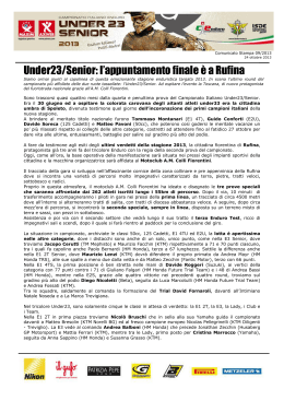
Information
Power Parts
90112935100
05. 2012
3.211.900
*3211900*
www.ktm.com
DEUTSCH
Danke, dass Sie sich für KTM Power Parts entschlossen haben.
Alle unsere Produkte wurden nach den höchsten Standards entwickelt und gefertigt, unter Verwendung der besten verfügbaren
Materialien.
KTM Power Parts sind rennerprobt und gewährleisten ultimative Performance.
KTM KANN NICHT VERANTWORTLICH GEMACHT WERDEN FÜR FALSCHE MONTAGE ODER VERWENDUNG DIESES PRODUKTS. Bitte
befolgen Sie die Montageanleitung. Fachmännische Beratung und korrekte Installation der KTM PowerParts durch einen autorisierten
KTM Händler sind unerlässlich, um das Optimum an Sicherheit und Funktionalität zu gewährleisten.
Danke.
ENGLISH
2
Thank you for choosing KTM Power Parts!
All of our products are designed and built to the highest standards using the finest materials available.
KTM Power Parts are race proven to offer the ultimate in performance.
KTM WILL NOT BE HELD LIABLE FOR IMPROPER INSTALLATION OR USE OF THIS PRODUCT. Please follow all instructions provided.
Professional advice and proper installation of the KTM PowerParts by an authorized KTM dealer are essential to provide maximum
safety and functions.
Thank you.
ITALIANO
2
Grazie per aver deciso di acquistare un prodotto KTM Power Parts.
Tutti i nostri prodotti sono stati sviluppati e realizzati secondo i massimi standard e con l'impiego dei migliori materiali disponibili.
Le KTM Power Parts sono collaudate nelle competizioni ed assicurano altissime prestazioni.
KTM NON PUÒ ESSERE RESA RESPONSABILE PER UN MONTAGGIO O USO IMPROPRIO DI QUESTO PRODOTTO. Per favore osservate le
istruzioni nel manuale d'uso. Al fine di garantire la massima sicurezza e il corretto funzionamento, è indispensabile farsi consigliare
da persone esperte e competenti e far eseguire l'installazione delle KTM PowerPart presso i concessionari KTM autorizzati.
Grazie.
FRANCAIS
2
Nous vous remercions d'avoir choisi KTM Power Parts.
Tous nos produits ont été développés et réalisés selon les plus hauts standards et en utilisant les meilleurs matériaux disponibles.
Les Power Parts de KTM ont fait leurs preuves en compétition et garantissent les meilleures performances.
LA RESPONSABILITÉ DE KTM NE SAURAIT ÊTRE ENGAGÉE EN CAS D'ERREUR DANS LE MONTAGE OU L'UTILISATION DE CE PRODUIT.
Il convient de respecter les instructions de montage.
Le conseil spécialisé et l'installation dans les règles de l'art des PowerParts KTM par un concessionnaire KTM agréé sont
indispensables pour assurer un maximum de sécurité et de fonctionnalité.
Merci.
ESPANOL
2
2
Gracias por haberse decidido por el Power Parts KTM.
Todos nuestros productos han sido desarrollados y producidos según los estándares más altos utilizando los mejores materiales
disponibles.
Las KTM Power Parts están probadas en competencia y garantizan un óptimo rendimiento.
NO SE PUEDE HACER RESPONSABLE A LA KTM POR UN MONTAJE O UN USO INCORRECTO DE ESTE PRODUCTO.
Le rogamos seguir las instrucciones para el montaje.
A fin de garantizar la máxima seguridad y un funcionamiento correcto es imprescindible acudir a un concesionario autorizado de KTM
para obtener el mejor asesoramiento técnico e instalar correctamente las KTM PowerParts.
Gracias.
8
7
2
4
1
Lieferumfang:
1x Montageblech Alarmsystem (1)
1x Reed Schalter selbstklebend (2)
1x Metamol 90x45x3 (3)
2x Mehrbereichsblechmutter M4 (4)
1x Kabelband 300/4.8 (5)
4x Blechschraube DIN7981 3.5x10 (6)
2x Zylinderschraube DIN912-M4x20-8.8 (7)
2x Bundschraube M6x10 (8)
90112935150
60012035185
59003001099
54603048500
44011076305
0981350103
0912040203
0025060106
6
3
3
Vorarbeiten
- Soziussitzbank abnehmen (siehe Bedienungsanleitung).
10
9
- Metamol (3) auf das Montageblech (1) aufkleben (Bild A).
4
4
- Mehrbereichsblechmuttern M4 (4) am Montageblech (1) aufschieben.
- Kabelband (5) durch die Öffnungen im Montageblech (1) fädeln.
3
- Montageblech (1) positionieren und mit den Bundschrauben M6x10 montieren.
5
1
A
11
B
- Alarmanlage (optional erhältlich) mit dem Stecker (9) verbinden und mit
der Gummiabdeckung (10) sichern.
4mm
- Gummiabdeckung (10) mit dem vormontierten Kabelband (5) sichern.
- Alarmanlage mit den Zylinderschrauben (7) auf das Montageblech (1)
montieren.
9 10
2a
7
- Reedschalter mit Kabel (2a) aufkleben und mit den Blechschrauben
DIN7981 3.5x10 (6) befestigen.
- Stecker (11) des Reedschalters mit dem Kabelstrang des Motorrades verbinden.
7
- Reedschalter (2b) an der Soziussitzbank montieren.
Original Soziussitzbank
- Reedschalter (2b) wie im Bild (C) gezeigt aufkleben und mit den
Blechschrauben DIN7981 3.5x10 (6) befestigen.
Soziussitzabdeckung (optional erhältlich)
- Reedschalter (2b) wie im Bild (D) gezeigt aufkleben.
2b
Nacharbeiten
C
DEUTSCH
5
D
- Soziussitzbank montieren (siehe Bedienungsanleitung) und Funktionsprüfung
(lt. Bedienungsanleitung Alarmanlage) durchführen.
5
8
7
2
4
1
Scope of supply:
1x mounting plate, alarm system (1)
1x reed switch, self-adhesive (2)
1x Metamol 90x45x3 (3)
2x range change metal nuts M4 (4)
1x cable tie 300/4.8 (5)
4x tapping screws DIN7981 3.5x10 (6)
2x cap head screws DIN912-M4x20-8.8 (7)
2x collar screws M6x10 (8)
60012035185
59003001099
54603048500
44011076305
0981350103
0912040203
0025060106
6
3
Preparations
ENGLISH
- Take off the passenger seat (see the Owner's Manual).
10
9
4
- Attach the Metamol (3) to the mounting plate (1) (Figure A).
4
4
- Slide the range change metal nuts M4 (4) onto the mounting plate (1).
- Thread the cable tie (5) through the openings in the mounting plate (1).
- Position the mounting plate (1) and mount with the collar screws M6x10.
3
5
1
A
11
B
- Connect the alarm system (optionally available) with the connector (9) and
secure with the rubber cover (10).
4mm
- Secure the rubber cover (10) with the premounted cable tie (5).
- Mount the alarm system onto the mounting plate (7) using the cap head
screws (1).
9 10
2a
7
- Attach the reed switch with the cable (2a) and screw it using the tapping
screws DIN7981 3.5x10 (6) .
- Connect the reed switch connector (11) with the motorcycle wiring harness.
7
- Mount the reed switch (2b) on the passenger seat.
Original passenger seat
- Attach the reed switch (2b) as shown in Figure (C) and secure it using the
tapping screws DIN7981 3.5x10 (6).
Passenger seat cover (optionally available)
- Attach the reed switch (2b) as shown in Figure (D).
2b
Final steps
C
D
- Mount the passenger seat (see the Owner's Manual) and perform a functional check (as described in the alarm system manual).
5
8
7
2
4
1
Volume della fornitura:
N. 1 piastrina di montaggio per l'impianto d'allarme (1)
N. 1 contatto Reed autoadesivo (2)
60012035185
N. 1 Metamol 90x45x3 (3)
59003001099
N. 2 dadi universali per lamiera M4 (4)
54603048500
N. 1 fascetta serracavi 300/4.8 (5)
44011076305
N. 4 viti autofilettanti DIN7981 3.5x10 (6)
0981350103
N. 2 viti a testa cilindrica DIN912-M4x20-8.8 (7)
0912040203
N. 2 viti flangiate M6x10 (8)
0025060106
6
3
Operazioni preliminari
- Rimuovere la sella passeggero (vedere il manuale d'uso).
10
9
- Applicare i dadi universali per lamiera M4 (4) sulla piastrina di montaggio (1).
- Far passare la fascetta serracavi (5) attraverso le aperture della piastrina
di montaggio (1).
3
5
- Posizionare la piastrina di montaggio (1) e montarla con le viti flangiate
M6x10.
1
A
11
B
5
- Collegare l'impianto d'allarme (disponibile opzionalmente) con il connettore (9) e assicurarlo con il rivestimento in gomma (10).
4mm
- Assicurare il rivestimento in gomma (10) con la fascetta serracavi premontata
(5).
- Con le viti a testa cilindrica (7) montare l'impianto d'allarme sulla piastrina
di montaggio (1).
9 10
2a
7
- Incollare il contatto Reed con il cavo (2a) e fissarlo con le viti autofilettanti DIN7981 3.5x10 (6).
- Collegare il connettore (11) del contatto Reed con il cablaggio della motocicletta.
7
- Montare il contatto Reed (2b) sulla sella passeggero.
Sella passeggero originale
- Incollare il contatto Reed (2b) come mostrato nella figura (C) e fissarlo
con le viti autofilettanti DIN7981 3.5x10 (6).
Coprisella passeggero (disponibile opzionalmente)
- Incollare il contatto Reed (2b) come mostrato nella figura (D).
2b
Operazioni successive
C
D
ITALIANO
- Incollare il Metamol (3) sulla piastrina di montaggio (1) (figura A).
4
4
- Montare la sella passeggero (vedere il manuale d'uso) ed effettuare il controllo funzionale (come descritto nel manuale d'uso dell'impianto d'allarme).
5
8
7
2
4
1
Contenu de la livraison :
1x Plaque de montage système d'alarme (1)
1x Contacteur Reed autocollant (2)
1x Metamol 90x45x3 (3)
2x Écrou multifonctions M4 (4)
1x Collier pour câbles 300/4.8 (5)
4x Vis à tôle DIN7981 3.5x10 (6)
2x Vis cylindrique DIN912-M4x20-8.8 (7)
2x Vis à épaulement M6x10 (8)
60012035185
59003001099
54603048500
44011076305
0981350103
0912040203
0025060106
6
3
Travaux préalables
- Déposer la selle passager (voir le manuel d'utilisation).
10
9
- Coller le metamol (3) sur la plaque de montage (1) (figure A).
4
4
- Introduire les écrous multifonctions M4 (4) dans la plaque de montage
(1).
- Faire passer le collier (5) par les passages pratiqués dans la plaque de
montage (1).
3
5
- Mettre en place la plaque de montage (1) et la monter avec les vis à épaulement M6x10.
1
A
FRANCAIS
6
11
B
- Raccorder l'alarme (disponible en option) au connecteur (9) et recouvrir
le tout du cache en caoutchouc (10).
4mm
- Bloquer le cache en caoutchouc (10) avec le collier pour câbles (5) mis
en place précédemment.
- Monter l'alarme avec les vis cylindrique (7) sur la tôle de montage (1).
9 10
2a
7
- Coller le contacteur Reed avec son câble (2a) et le fixer l'aide des vis DIN7981
3.5x10 (6).
- Connecter la fiche (11) du contacteur Reed avec le faisceau de câbles de
la moto.
7
- Monter le contacteur Reed (2b) dans la selle passager.
Selle passager d'origine
- Coller le contacteur Reed (2b) comme illustré sur la figure (C) et le fixer
avec les vis DIN7981 3.5x10 (6).
Cache de selle passager (disponible en option)
- Coller le contacteur Reed (2b) comme illustré en figure (D).
2b
Travaux ultérieurs
C
D
- Monter la selle passager (voir le manuel d'utilisation) et vérifier le fonctionnement de l'alarme (en suivant les instructions du manuel d'utilisation
de l'alarme).
5
8
7
2
4
1
Volumen de suministro:
1x chapa de montaje del sistema de alarma (1)
1x interruptor de lengüeta autoadhesivo (2)
1x metamol 90x45x3 (3)
2x tuercas multirrango para chapa M4 (4)
1x cinta sujetacables 300/4.8 (5)
4x tornillos para chapa DIN7981 3.5x10 (6)
2x tornillos cilíndricos DIN912-M4x20-8.8 (7)
2x tornillos de collarín M6x10 (8)
60012035185
59003001099
54603048500
44011076305
0981350103
0912040203
0025060106
6
3
Trabajos previos
- Quitar el asiento del acompañante (véase el manual de instrucciones).
10
9
- Pegar el metamol (3) a la chapa de montaje (1) (figura A).
4
4
- Colocar las tuercas multirrango para chapa M4 (4) en la chapa de montaje (1).
- Pasar la cinta sujetacables (5) por los orificios de la chapa de montaje (1).
3
- Posicionar la chapa de montaje (1) y montarla con los tornillos de collarín M6x10.
5
1
A
11
B
- Conectar el equipo de alarma (disponible) con el conector (9) y asegurarlo
con la cubierta de goma (10).
4mm
- Asegurar la cubierta de goma (10) con la cinta sujetacables premontada
(5).
- Montar el equipo de alarma con los tornillos cilíndricos (7) en la chapa de
montaje (1).
9 10
2a
- Conectar el conector (11) del interruptor de lengüeta con el ramal de cables
de la motocicleta.
7
- Montar el interruptor de lengüeta (2b) en el asiento del acompañante.
Asiento del acompañante original
- Pegar el interruptor de lengüeta (2b) tal como se muestra en la figura (C)
y fijarla con los tornillos para chapa DIN7981 3.5x10 (6).
Cubierta del asiento del acompañante (opcional)
- Pegar el interruptor de lengüeta (2b) tal como se muestra en la figura (D).
2b
Trabajos posteriores
C
D
- Montar el asiento del acompañante (véase el manual de instrucciones) y
realizar una prueba de funcionamiento (de acuerdo con el manual de
instrucciones del equipo de alarma).
ESPANOL
7
- Pegar el interruptor de lengüeta con el cable (2a) y fijarlo con los tornillos para chapa DIN7981 3.5x10 (6).
7
Scaricare