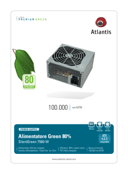
CC
Ventilatori assiali intubati
Duct axial fan
DESCRIZIONE GENERALE
sez.
4
pag.
2
I ventilatori assiali intubati della serie CC sono utilizzati
in applicazioni canalizzate che necessitano di grandi
portate d’aria con cadute di pressione non elevate,
come ad esempio impianti di ventilazione e raffreddamento in ambito industriale, navale, commerciale,
civile, energetico... Questa serie presenta, rispetto ai
ventilatori centrifughi, il vantaggio di un minor ingombro e una maggiore facilità d’installazione. La serie
standard è costituita da modelli con diametro della
ventola da 310 a 1600 mm. Possono essere realizzati
con motori di diversa polarità a seconda della taglia e
delle prestazioni richieste. Sono idonei a convogliare
aria pulita con temperatura da –10°C a +50°C in servizio continuo.
è disponibile la versione antideflagrante CC-ATX costruita e certificata in conformità alla Direttiva ATEX
94/9 CE ed il suo impiego è previsto con aria pulita
-10°C / +40°C. Tali serie sono adatte all’installazione
in zona 1/21, cioe’ in aree o ambienti dove sia necessario garantire un elevato fattore di sicurezza contro le
esplosioni, dovuti a gas (II2G) e/o polveri infiammabili (II2D/II2GD). Questi apparecchi sono certificati da
Ente Notificato secondo la norma 94/9 CE.
The tube axial fans of CC series are used for ducted
installations requiring large airflow with relatively
low pressure drop, like ventilation and cooling systems in industrial, naval, commercial, civil, energetic fields. This series has, compared to centrifugal
fans, the advantage of being smaller in dimensions
and easier to be installed. The series consists of
different sizes with impeller diameter from 310 to
1600 mm. CC fans can be fitted with motors of
different polarity, depending on size and required
performance. Suitable for conveying clean air with
temperature from –10 °C to +50°C in continuous
service. The explosion-proof version CC-ATX is certified by a Notified Body according to the 94/9/CE
Atex Directive and is suitable to convey clean air in
the temperature range -10°C +40°C. This version is
suitable for installation in zone 1/21, that are areas
where it is necessary to guarantee high security
against explosions and fires due to presence of
flammable gas(II2G) and/or dusts (II2D/II2GD).
CONSTRUCTION
• Cassa in lamiera d’acciaio, con flange di fissaggio,
realizzate a norma UNI ISO 6580 – EUROVENT.
Verniciata a polveri epossipoliestiriche.
• Girante con pale a profilo alare in nylon-vetro (antistatico per CC-ATX) e mozzo in fusione di lega
d’alluminio. Bilanciata secondo ISO 1940. Angolo
di calettamento variabile da fermo tramite tasselli
di regolazione
• Esecuzione 4 (accoppiamento diretto con girante a
sbalzo) e flusso aria da motore a girante.
• Motorizzazioni:
- CC- motore asincrono trifase o monofase a norme internazionali IEC 60034, IEC 60072, EMC
2004/108/CE, LVD 2006/95/CE e marcato CE IP55,
classe F.
- CC-ATX: motore asincrono trifase o monofase II2G,
II2D, II2GD a norme internazionali IEC 60034, IEC
60072, IEC 60079 e/o IEC 61241, EMC 2004/108/
CE, LVD 2006/95/CE, con certificati ATEX e marcatura CE, IP 55/IP 65, classe F.
- Tutti idonei ad un servizio S1 (funzionamento continuo a carico costante).
•Short casing in steel sheet, with fixing flanges
manufactured according to UNI ISO 6580-EUROVENT standard. Protected against atmospheric agents by epoxy paint.
•Axial impeller with aerofoil profile blades in
glass reinforce polyamide and die-cast aluminium hub, balanced according ISO 1940. Variable pitch angle in still position with setting
means.
•Execution 4 (with impeller directly coupled to
motor with feet) and airflow from motor to impeller.
•Motorizations:
-CC: asynchronous three-phase or single-phase
motors according to international standards
IEC 600034, IEC 60072, EMC 2004/108/CE,
LVD 2006/95/CE, CE marked, IP 55, class F.
-CC-ATX: asynchronous three-phase motors
or single-phase II2G,II2D,II2GD according to
international standards IEC 60034, IEC 60072,
IEC 60079 and/or IEC61241, EMC 2004/108/
CE, LVD 2006/95/CE, with Atex certification,
CE marked, IP55/IP 65, class F.
-All motors suitable to S1 service (continuous
working at constant load).
ACCESSORI
ACCESSORIES
COSTRUZIONE
•Prolunga con portellina d’ispezione (CCpro)
•Rete di protezione piana (CCr)
•Rete di protezione conica (CCrc)
•Giunto antivibrante (CCga)
•Staffe di fissaggio (CCst)
•Boccaglio in aspirazione/mandata (CCbo)
•Silenziatori con e senza ogiva con tre diverse
lunghezze (CCsa e CCsb)
•Controflange (CCf)
•Controflange con collare (CCfc)
•Supporti antivibranti
A RICHIESTA
• Prestazioni diverse da quelle rappresentate.
• Girante a profilo alare, completamente in fusione
di lega d’alluminio.
• Cassa zincata a caldo.
• Flusso aria da girante a motore.
• Morsettiera esterna.
• Versioni “multistadio” isorotanti o controrotanti.
• Versioni trasportabili, con cassa supportata da
cavalletto (CCP).
• Versioni con trasmissione mediante cinghie trapezoidali in esecuzione 9 o 12 (CCT).
68
GENERAL DESCRIPTION
•Extension (for long casing version) with inspection porthole (CCpro)
•Flat protection guard (CCr)
•Conic protection guard (CCrc)
•Flexible connectors (CCga)
•Support feet (CCst)
•Inlet/outlet bell mouth (CCbo)
•Silencers, with and without pod, in three lengths (CCsa and CCsb)
•Counter flange (Ccf)
•Counter flange with collar (CCfc)
•Anti-vibration mounts.
UPON REQUEST
• Performances differing from standard
• Impeller with airfoil blades in die-cast aluminium alloy
• Casing protected against atmospheric agents by hotdip galvanizing
• Air flow from impeller to motor
• Outer terminal box
• Multistage versions (iso-rotating or contra-rotating)
• Portable versions, with casing support (CCP)
• Belt drive versions in execution 9 or 12 with transmission through trapezoidal belts (CCT)
ESECUZIONI Executions
CC
CASSA CORTA Short Casing
I ventilatori della serie CC sono in esecuzione a cassa corta di standard, per semplicità d’ installazione, movimentazione e contenimento dei costi. Quest’esecuzione è anche concepita per il
montaggio nella parte iniziale o finale di una canalizzazione. In questo caso, una corretta installazione prevede l’utilizzo del boccaglio “CCbo” (vedere accessori).
The fans of CC series are in short casing execution as standard, for ease of transport and installation and for cost saving. This execution is also suitable for assembling in the initial or final
part of a ducted system. In this case a correct installation foresees the use of the inlet/outlet bell
mouth “CCbo” (see accessories).
CASSA LUNGA Long Casing
I ventilatori della serie CC possono essere forniti in esecuzione a cassa lunga, con girante e
motore completamente protetti dalla cassa, utilizzando la prolunga “CCpro” (vedere accessori).
La prolunga “CCpro” è completa di portellina d’ispezione e fori per passaggio cavi.
The CC series fans can be provided in long casing execution, with impeller and motor completely
protected inside the casing, by using the extension “CCpro” (see accessories).
The extension “ CCpro” is complete of inspection porthole and holes for cable entry.
sez.
pag.
MULTISTATDIO Multistage
I ventilatori della serie CC, prevedono la possibilità d’esecuzioni multistadio, isorotanti o controrotanti (assemblaggio di due o più ventilatori monostadio con giranti rotanti nello stesso senso
o in senso contrario). Queste configurazioni permettono di aumentare notevolmente la pressione
sviluppata. In particolare la serie CC a due stadi controrotanti, sviluppa 2.5 volte la pressione
sviluppata da un ventilatore monostadio, di pari diametro e velocità con un assorbimento di
potenza non superiore alle 2 volte. Inoltre il ventilatore multistadio ha un rapporto prestazioni/
livello sonoro vantaggioso, rispetto ad un ventilatore monostadio, potendo raggiungere le prestazioni richieste ad una minore velocità di rotazione.
The fans of the CC series foresee the possibility of multistage execution, iso-rotating or contrarotating (assembly of two or more single-stage fans, with impellers rotating in the same or in the
opposite direction). This configuration allows to considerably increase the pressure developed.
Specifically, the CC series with two contra-rotating stages develops 2.5 times the pressure of a
single-stage fan of equal diameter and speed, with a power absorption not bigger than 2 times. In
addition, the multi-stage option, compared to the single-stage one, has a favourable relation performances/ noise, as the required performance can be achieved with a lower rotational speed.
Flusso da MOTORE a GIRANTE (Orientamento standard)
Standard airflow from MOTOR to IMPELLER
Flusso da GIRANTE a MOTORE (Orientamento a richiesta)
Upon request airflow from IMPELLER to motor
69
4
3
PRESTAZIONI Performance
CC
Frequenza 50Hz – Temperatura dell’aria 15°C – Pressione barometrica 760 mm Hg – Peso specifico dell’aria 1,22 Kg/m3
Frequency 50Hz – Air temperature 15°C – Barometric pressure 760 mm Hg – Air specific weight 1,22 Kg/m3
Lp: livello di pressione sonora rilevato a 3 m - Lp: sound pression level measured at 3 m
Nota: in questo catalogo è rappresentata una selezione, delle prestazioni ottenibile con la serie
CC, in grado di risolvere un elevato numero di problematiche aerauliche. La scelta ha lo scopo di coniugare costo/prestazioni e tempi di consegna. A richiesta il nostro servizio
tecnico è in grado di configurare apparecchi per numerose differenti esigenze.
Note: in this catalogue , a selection only of the performances obtainable with the CC series is shown, able to solve several demands
and chosen to combine cost/ performances and delivery
time. Upon request, our technical service is able to
design several different configurations and installations, based on customer specs.
sez.
4
pag.
Hs
Hs
[kgf/m²] [Pa]
4
19
CC 310
Tipo
Type
Mot. Lp
(Gr) dB (A)
15
Modello
Model
U
P
Pm
(kW)
In
(A)
IP/CL
CC
314-A
M
4
0,12
1,10
55/F
63
51
CC
314-A
T
4
0,12
0,45
55/F
63
51
8
CC
314-B
M
4
0,12
1,10
55/F
63
48
CC
314-B
T
4
0,12
0,45
55/F
63
48
5.5
CC
312
M
2
0,25
1,85
55/F
63
67
CC
312
T
2
0,25
0,71
55/F
63
67
CC - ATX
314-A
M
4
0,12
1,30
55/F
63
51
CC - ATX
314-A
T
4
0,12
0,47
55/F
63
51
0.75
CC - ATX
314-B
M
4
0,12
1,30
55/F
63
48
CC - ATX
314-B
T
4
0,12
0,47
55/F
63
48
0.17
CC - ATX
312
M
2
0,25
2,20
55/F
63
67
CC - ATX
312
T
2
0,25
0,64
55/F
63
67
11
3.4
1.8
125
95
65
44
314-B 314-A
26
13
4.8
0.55
1400
0.35
Hs
Hs
[kgf/m²] [Pa]
25 250
CC 350
Mot. Lp
(Gr) dB (A)
19
Modello
Model
U
P
Pm
(kW)
In
(A)
IP/CL
CC
354-A
M
4
0,12
1,10
55/F
63
55
CC
354-A
T
4
0,12
0,45
55/F
63
55
10
CC
354-B
M
4
0,12
1,10
55/F
63
52
CC
354-B
T
4
0,12
0,45
55/F
63
52
7
CC
352
M
2
0,55
3,60
55/F
71
73
CC
352
T
2
0,55
1,60
55/F
71
73
CC - ATX
354-A
M
4
0,12
1,30
55/F
63
55
CC - ATX
354-A
T
4
0,12
0,47
55/F
63
55
CC - ATX
354-B
M
4
0,12
1,30
55/F
63
52
CC - ATX
354-B
T
4
0,12
0,47
55/F
63
52
CC - ATX
352
M
2
0,55
4,50
55/F
71
73
CC - ATX
352
T
2
0,55
1,26
55/F
71
73
Attenzione: non utilizzare le versioni a 2 poli nelle applicazionia bocca libera o con modeste perdite di carico!
Caution: do not use 2 poles versionin free uinlet application or withsmall charge losses!
70
312
160
Attenzione: non utilizzare le versioni a 2 poli nelle applicazionia bocca libera o con modeste perdite di carico!
Caution: do not use 2 poles versionin free uinlet application or withsmall charge losses!
Tipo
Type
Hsta
200
14
4.4
2.4
1
0.23
1750
0.45
2100 2450
Q [m³/h]
0.55 0.65
Q [m³/s]
2800
0.75
3150
0.85
3500
0.95
Hsta
352
200
155
115
80
50
354-B
354-A
30
15
5
0.41
1800 2400 3000 3600 4200 4800 5400 6000
Q [m³/h]
0.45
0.6
0.75
0.9
1.05 1.2
Q [m³/s]
1.35
1.5
1.65
PRESTAZIONI Performance
CC
Frequenza 50Hz – Temperatura dell’aria 15°C – Pressione barometrica 760 mm Hg – Peso specifico dell’aria 1,22 Kg/m3
Frequency 50Hz – Air temperature 15°C – Barometric pressure 760 mm Hg – Air specific weight 1,22 Kg/m3
Lp: livello di pressione sonora rilevato a 3 m - Lp: sound pression level measured at 3 m
Hs
Hs
[kgf/m²] [Pa]
35 350
CC 400
Tipo
Type
27
Modello
Model
U
P
Pm
(kW)
In
(A)
IP/CL
Mot. Lp
(Gr) dB (A)
CC
404-A
M
4
0,18
1,65
55/F
63
59
CC
404-A
T
4
0,18
0,60
55/F
63
59
CC
404-B
M
4
0,18
1,65
55/F
63
56
CC
404-B
T
4
0,18
0,60
55/F
63
56
CC
402
M
2
1,10
6,20
55/F
80
76
6.5
CC
402
T
2
1,10
2,50
55/F
80
76
CC - ATX
404-A
M
4
0,18
1,70
55/F
63
59
3.6
CC - ATX
404-A
T
4
0,18
0,64
55/F
63
59
1.6
CC - ATX
404-B
M
4
0,18
1,70
55/F
63
56
CC - ATX
404-B
T
4
0,18
0,64
55/F
63
56
0.43
CC - ATX
402
M
2
1,10
8,60
55/F
80
76
CC - ATX
402
T
2
1,10
2,50
55/F
80
76
21
15
10
220
165
120
Modello
Model
P
Pm
(kW)
In
(A)
U
CC
454-A
CC
454-A
CC
454-B
CC
CC
CC
CC
CC
Mot. Lp
(Gr) dB (A)
IP/CL
M
4
0,37
3,30
55/F
71
63
T
4
0,37
1,18
55/F
71
63
M
4
0,37
3,30
55/F
71
60
454-B
T
4
0,37
1,18
55/F
71
60
454-C
M
4
0,18
1,65
55/F
63
59
454-C
T
4
0,18
0,60
55/F
63
59
452
M
2
2,20
13,50
55/F
90
80
452
T
2
2,20
5,30
55/F
90
80
CC - ATX
454-A
M
4
0,37
3,10
55/F
71
63
CC - ATX
454-A
T
4
0,37
1,22
55/F
71
63
CC - ATX
454-B
M
4
0,37
3,10
55/F
71
60
CC - ATX
454-B
T
4
0,37
1,22
55/F
71
60
CC - ATX
454-C
M
4
0,18
1,70
55/F
63
59
CC - ATX
454-C
T
4
0,18
0,68
55/F
63
59
CC - ATX
452
T
2
2,20
4,64
55/F
90
80
50
26
10
1.6
0.65 0.85 1.05 1.25 1.45 1.65 1.85
Q [m³/s]
48
480
36
370
26
18
11
6
2.6
0.65
Hsta
200
135
454-B
80
454-A
42
16
2.2
3
4
0.9
1.2
7
70
5
50
3.4
34
2.2
22
1.2
12
65
0.55
5.5
63
0.15
1.5
P
Pm
(kW)
In
(A)
IP/CL
Mot. Lp
(Gr) dB (A)
CC
504-A
M
4
0,55
4,40
55/F
80
65
CC
504-A
T
4
0,55
1,60
55/F
80
65
CC
504-B
M
4
0,55
4,40
55/F
80
63
CC
504-B
T
4
0,55
1,60
55/F
80
63
CC
506
M
6
0,15
1,40
55/F
71
55
CC
506
T
6
0,18
0,70
55/F
71
55
CC
508
T
8
0,09
0,56
55/F
71
47
CC - ATX
504-A
T
4
0,55
1,75
55/F
80
CC - ATX
504-B
T
4
0,55
1,75
55/F
80
CC - ATX
506
T
6
0,18
0,69
55/F
71
55
CC - ATX
508
T
8
0,09
0,56
55/F
71
47
pag.
280
9.5
U
2.2
452
95
Modello
Model
2
sez.
5
Hs
Hs
[kgf/m²] [Pa]
12 120
CC 500
404-A
404-B
80
Hs
Hs
[kgf/m²] [Pa]
60 600
CC 450
Tipo
Type
402
280
2400 3200 4000 4800 5600 6400 7200 8000
Q [m³/h]
Attenzione: non utilizzare le versioni a 2 poli nelle applicazionia bocca libera o con modeste perdite di carico!
Caution: do not use 2 poles versionin free uinlet application or withsmall charge losses!
Tipo
Type
Hsta
1.5
6
7
8
9
Q [m³/h] x 1000
1.8 2.1 2.4
Q [m³/s]
10
2.75
11
3
12
3.35
Hsta
504-A
504-B
506
508
2.3
3 3.7 4.4 5.1 5.8 6.5 7.2 7.9 8.6 9.3 10
Q [m³/h] x 1000
0.8
1
1.2 1.4 1.6 1.8
Q [m³/s]
2
2.2 2.4 2.6 2.8
71
4
5
PRESTAZIONI Performance
CC
Frequenza 50Hz – Temperatura dell’aria 15°C – Pressione barometrica 760 mm Hg – Peso specifico dell’aria 1,22 Kg/m3
Frequency 50Hz – Air temperature 15°C – Barometric pressure 760 mm Hg – Air specific weight 1,22 Kg/m3
Lp: livello di pressione sonora rilevato a 3 m - Lp: sound pression level measured at 3 m
Hs
Hs
[kgf/m²] [Pa]
14 140
CC 560
Tipo
Type
sez.
Modello
Model
U
P
Pm
(kW)
In
(A)
IP/CL
Mot. Lp
(Gr) dB (A)
CC
564-A
M
4
0,75
5,60
55/F
80
70
CC
564-A
T
4
0,75
2,20
55/F
80
70
CC
564-B
M
4
0,75
5,60
55/F
80
65
CC
564-B
T
4
0,75
2,20
55/F
80
65
CC
566
M
6
0,26
2,20
55/F
80
58
CC
566
T
6
0,26
1,00
55/F
71
58
CC
568
T
8
0,15
0,75
55/F
71
51
CC - ATX
564-A
T
4
0,75
2,11
55/F
80
70
CC - ATX
564-B
T
4
0,75
2,11
55/F
80
65
CC - ATX
566
T
6
0,25
0,89
55/F
71
58
CC - ATX
568
T
8
0,18
0,87
55/F
80
51
564-A
11
110
8.5
85
6
60
4.2
42
2.6
28 568
1.5
16
0.7
7.5
0.19
2.4
564-B
566
3
4
5
6
7 8 9 10 11 12 13 14
Q [m³/h] x 1000
0.9 1.2 1.5 1.8 2.1 2.4 2.7
Q [m³/s]
4
pag.
Hsta
Hs
Hs
[kgf/m²] [Pa]
14 140
6
CC 630
Tipo
Type
Modello
Model
U
P
Pm
(kW)
In
(A)
IP/CL
Mot. Lp
(Gr) dB (A)
CC
634-A
M
4
1,10
7,70
55/F
90S
74
CC
634-A
T
4
1,10
2,70
55/F
90S
74
CC
634-B
M
4
1,10
7,70
55/F
90S
71
CC
634-B
T
4
1,10
2,70
55/F
90S
71
CC
636
M
6
0,37
3,00
55/F
80
CC
636
T
6
0,37
1,20
55/F
CC
638
T
8
0,26
1,10
55/F
CC - ATX
634-A
T
4
1,10
2,80
CC - ATX
634-B
T
4
1,10
CC - ATX
636
T
6
0,37
CC - ATX
638
T
8
0,25
11
110
8.5
85
6
60
3
3.3 3.6 3.9
Hsta
634-A
634-B
636
4.2
42 638
64
2.6
28
80
64
1.5
16
80
58
55/F
90S
74
0.7
7.5
2,80
55/F
90S
71
0.19
2.4
1,37
55/F
80
64
1,17
55/F
80
58
4.5
6
7.5
9 10.5 12 13.5 15 16.5 18
Q [m³/h] x 1000
1.4 1.8 2.2 2.6 3 3.4 3.8 4.2 4.6
Q [m³/s]
Hs
Hs
[kgf/m²] [Pa]
18 180
CC 710
Tipo
Type
Modello
Model
U
CC
714-A
T
CC
714-B
CC
CC
Mot. Lp
(Gr) dB (A)
14
Pm
(kW)
In
(A)
IP/CL
4
2,20
5,30
55/F
100L
77
T
4
2,20
5,30
55/F
100L
71
7
716
T
6
0,75
2,40
55/F
90S
66
4.8
718
T
8
0,37
1,70
55/F
90S
60
3
CC - ATX
714-A
T
4
2,20
5,07
55/F
100L
77
CC - ATX
714-B
T
4
2,20
5,07
55/F
100L
71
CC - ATX
716
T
6
0,75
2,23
55/F
90S
66
CC - ATX
718
T
8
0,37
1,55
55/F
90S
60
P
10
1.6
0.65
0.14
Hsta
714-A
714-B
145
110
80
716
55
36
718
20
9.5
3
5
6.5
1.6
72
5
8
2
9.5
11 12.5 14 15.5 17 18.5 20
Q [m³/h] x 1000
2.4 2.8 3.2 3.6 4
Q [m³/s]
4.4 4.8 5.2 5.6
PRESTAZIONI Performance
CC
Frequenza 50Hz – Temperatura dell’aria 15°C – Pressione barometrica 760 mm Hg – Peso specifico dell’aria 1,22 Kg/m3
Frequency 50Hz – Air temperature 15°C – Barometric pressure 760 mm Hg – Air specific weight 1,22 Kg/m3
Lp: livello di pressione sonora rilevato a 3 m - Lp: sound pression level measured at 3 m
Hs
Hs
[kgf/m²] [Pa]
40 400
CC 800 - 4 poli
Tipo
Type
32
320
Modello
Model
U
P
Pm
(kW)
In
(A)
IP/CL
Mot. Lp
(Gr) dB (A)
24
250
CC
804-A
T
4
5,50
13
55/F
112M
81
18
190
CC
804-B
T
4
4,00
8,50
55/F
112M
77
CC
804-C
T
4
3,00
6,80
55/F
100L
76
CC - ATX
804-A
T
4
4,00
8,60
55/F
112M
78
7.5
CC - ATX
804-B
T
4
4,00
8,60
55/F
112M
77
4.4
CC - ATX
804-C
T
4
3,00
6,88
55/F
100L
76
2
12
0.6
Hsta
804-A
804-B
804-C
135
90
55
28
10
1.3
14
16
18 20 22 24
Q [m³/h] x 1000
26
28
30
3.8 4.3 4.8 5.3 5.8 6.3 6.8 7.3 7.8 8.3
Q [m³/s]
Hs
Hs
[kgf/m²] [Pa]
16 160
CC 800 - 6 poli
Tipo
Type
12
125
Modello
Model
U
P
Pm
(kW)
In
(A)
IP/CL
Mot. Lp
(Gr) dB (A)
CC
806-A
T
6
1,50
4,20
55/F
100L
67
CC
806-B
T
6
1,10
3,50
55/F
90L
66
CC
806-C
T
6
1,10
3,50
55/F
90L
65
CC - ATX
806-A
T
6
1,50
4,40
55/F
100L
67
3
32
CC - ATX
806-B
T
6
1,10
2,98
55/F
90L
66
1.7
19
CC - ATX
806-C
T
6
1,10
2,98
55/F
90L
65
0.8
9.5
0.23
3.2
9
6.5
4.6
95
sez.
Hsta
pag.
806-A
806-B
806-C
70
50
0.27
8
9.5
2.3
Hs
[kgf/m²]
9
CC 800 - 8 poli
Tipo
Type
Hs
[Pa]
90
7
70
5
50
3.6
36
Modello
Model
U
P
Pm
(kW)
In
(A)
IP/CL
Mot. Lp
(Gr) dB (A)
CC
808-A
T
8
0,55
2,50
55/F
90L
61
CC
808-B
T
8
0,55
2,50
55/F
90L
60
CC
808-C
T
8
0,37
1,70
55/F
90L
59
2.4
24
CC - ATX
808-A
T
8
0,55
1,98
55/F
90L
61
1.5
15
CC - ATX
808-B
T
8
0,55
1,98
55/F
90L
60
0.8
8.5
CC - ATX
808-C
T
8
0,37
1,55
55/F
90L
59
0.35
3.8
0.08
1
11
2.7
12.5 14 15.5
Q [m³/h] x 1000
17
18.5
3.5 3.9 4.3
Q [m³/s]
4.7
5.1
3.1
20
5.5
Hsta
808-A
808-B
808-C
7
1.75 2
8
9 10 11 12
Q [m³/h] x 1000
2.3
2.6
2.9 3.2
Q [m³/s]
13
3.5
14
3.8
15
4.1
16
4.45
73
4
7
PRESTAZIONI Performance
CC
Frequenza 50Hz – Temperatura dell’aria 15°C – Pressione barometrica 760 mm Hg – Peso specifico dell’aria 1,22 Kg/m3
Frequency 50Hz – Air temperature 15°C – Barometric pressure 760 mm Hg – Air specific weight 1,22 Kg/m3
Lp: livello di pressione sonora rilevato a 3 m - Lp: sound pression level measured at 3 m
Hs
Hs
[kgf/m²] [Pa]
50 500
CC 900 - 4 poli
Tipo
Type
Modello
Model
U
CC
904-A
CC
CC
Hsta
904-A
40
400
904-B
30
310
904-C
22
230
P
Pm
(kW)
In
(A)
IP/CL
Mot. Lp
(Gr) dB (A)
T
4
9,20
18,50
55/F
132M
85
904-B
T
4
7,50
14,70
55/F
132M
84
904-C
T
4
5,50
11,30
55/F
132S
80
CC - ATX
904-A
T
4
8,80
18,50
55/F
132M
85
9.5
CC - ATX
904-B
T
4
7,50
15,70
55/F
132M
84
5.5
CC - ATX
904-C
T
4
5,50
11,20
55/F
132S
80
15
2.6
0.8
165
110
65
32
11
1.1
23
sez.
6.5
4
pag.
26
CC 900 - 6 poli
Tipo
Type
7.5
Hs
Hs
[kgf/m²] [Pa]
25 250
8
19
Modello
Model
U
P
Pm
(kW)
In
(A)
IP/CL
Mot. Lp
(Gr) dB (A)
CC
906-A
T
6
3,20
7,00
55/F
132M
74
CC
906-B
T
6
2,20
5,32
55/F
112M
73
CC
906-C
T
6
2,20
5,32
55/F
112M
71
CC - ATX
906-A
T
6
3,00
7,90
55/F
132M
74
4.4
CC - ATX
906-B
T
6
2,20
5,60
55/F
112M
73
2.4
CC - ATX
906-C
T
6
2,20
5,60
55/F
112M
71
14
10
7
1
0.23
155
U
CC
908-A
CC
12
50
30
15
5
0.41
125
P
IP/CL
Mot. Lp
(Gr) dB (A)
T
8
1,50
4,60
55/F
112M
68
908-B
T
8
1,10
3,90
55/F
100L
66
CC
908-C
T
8
1,10
3,90
55/F
100L
64
CC - ATX
908-A
T
8
1,50
4,20
55/F
112M
68
3
32
CC - ATX
908-B
T
8
1,10
3,99
55/F
100L
66
1.7
19
CC - ATX
908-C
T
8
1,10
3,99
55/F
100L
64
0.8
9.5
0.23
3.2
4.6
9.5 10.5 11.5 12.5 13.5
Q [m³/s]
80
In
(A)
6.5
50
115
Pm
(kW)
9
47
906-C
17
Hs
Hs
[kgf/m²] [Pa]
16 160
Modello
Model
8.5
44
906-A
906-B
200
4.5
Tipo
Type
32 35 38 41
Q [m³/h] x 1000
Hsta
15
CC 900 - 8 poli
29
95
19
21 23 25 27
Q [m³/h] x 1000
5.5
6.5
7.5
Q [m³/s]
29
31
33
8.5
35
9.5
Hsta
908-A
908-B
908-C
70
50
0.27
9.5 11
2.6
74
13
15
17
19
Q [m³/h] x 1000
21
23
3 3.4 3.8 4.2 4.6 5 5.4 5.8 6.2 6.6
Q [m³/s]
25
7
PRESTAZIONI Performance
CC
Frequenza 50Hz – Temperatura dell’aria 15°C – Pressione barometrica 760 mm Hg – Peso specifico dell’aria 1,22 Kg/m3
Frequency 50Hz – Air temperature 15°C – Barometric pressure 760 mm Hg – Air specific weight 1,22 Kg/m3
Lp: livello di pressione sonora rilevato a 3 m - Lp: sound pression level measured at 3 m
Hs
Hs
[kgf/m²] [Pa]
Hsta
60 600 1004-A
48 480 1004-B
CC 1000 - 4 poli
Tipo
Type
Modello
Model
U
P
Pm
(kW)
CC
1004-A
T
4
CC
1004-B
T
CC
1004-C
T
CC - ATX
1004-A
CC - ATX
CC - ATX
In
(A)
IP/CL
Mot. Lp
(Gr) dB (A)
15,00 29,00
55/F
160L
87
4
9,20
18,50
55/F
132M
84
4
7,50
14,70
55/F
132M
82
T
4
15,00 29,00
55/F
160L
87
11
1004-B
T
4
11,00 21,00
55/F
160M
84
6
1004-C
T
4
7,50
55/F
132M
82
15,70
36
26
18
2.6
0.65
370 1004-C
280
200
135
80
42
16
2.2
30
8.5
35
18
185 1006-C
U
P
Pm
(kW)
In
(A)
IP/CL
Mot. Lp
(Gr) dB (A)
CC
1006-A
T
6
5,50
12,30
55/F
132M
76
CC
1006-B
T
6
4,00
9,10
55/F
132M
74
CC
1006-C
T
6
3,00
7,00
55/F
132S
71
CC - ATX
1006-A
T
6
5,50
12,36
55/F
132M
76
5.5
CC - ATX
1006-B
T
6
4,00
9,60
55/F
132M
74
3.2
CC - ATX
1006-C
T
6
3,00
7,90
55/F
132S
71
13
9
1.5
0.43
70
75
80
Hsta
1006-A
240 1006-B
Modello
Model
65
sez.
24
Tipo
Type
45 50 55 60
Q [m³/h] x 1000
10 11.5 13 14.5 16 17.5 19 20.5 22
Q [m³/s]
Hs
Hs
[kgf/m²] [Pa]
30 300
CC 1000 - 6 poli
40
pag.
140
100
65
40
20
7.5
0.9
20 23 26 29 32 35 38 41 44 47 50
Q [m³/h] x 1000
5
CC 1000 - 8 poli
6
Hs
Hs
[kgf/m²] [Pa]
16 160
1008-A
125 1008-B
12
1008-C
95
9
Tipo
Type
Modello
Model
U
P
Pm
(kW)
In
(A)
IP/CL
Mot. Lp
(Gr) dB (A)
CC
1008-A
T
8
2,20
5,70
55/F
132S
70
CC
1008-B
T
8
1,50
4,60
55/F
112M
67
CC
1008-C
T
8
1,10
3,90
55/F
100L
65
CC - ATX
1008-A
T
8
2,20
5,83
55/F
132S
70
3
32
CC - ATX
1008-B
T
8
1,50
4,20
55/F
112M
67
1.7
19
CC - ATX
1008-C
T
8
1,10
3,99
55/F
100L
65
0.8
9.5
0.23
3.2
6.5
4.6
7
8
9
10
Q [m³/s]
11
12
13
14
22 25 28 31
Q [m³/h] x 1000
34
37
40
Hsta
70
50
0.27
13
16
4
19
5
6
7
8
Q [m³/s]
9
10
11
75
4
9
PRESTAZIONI Performance
CC
Frequenza 50Hz – Temperatura dell’aria 15°C – Pressione barometrica 760 mm Hg – Peso specifico dell’aria 1,22 Kg/m3
Frequency 50Hz – Air temperature 15°C – Barometric pressure 760 mm Hg – Air specific weight 1,22 Kg/m3
Lp: livello di pressione sonora rilevato a 3 m - Lp: sound pression level measured at 3 m
30
Hs
[Pa]
300
24
240
185
Hs
[kgf/m²]
CC 1120 - 6 poli
Tipo
Type
Modello
Model
U
P
Pm
(kW)
In
(A)
IP/CL
Mot. Lp
(Gr) dB (A)
18
CC
1126-A
T
6
7,50
15,20
55/F
160M
79
13
CC
1126-B
T
6
5,50
12,30
55/F
132M
78
CC
1126-C
T
6
5,50
12,30
55/F
132M
76
CC - ATX
1126-A
T
6
7,50
15,75
55/F
160M
79
5.5
CC - ATX
1126-B
T
6
5,50
12,36
55/F
132M
78
3.2
CC - ATX
1126-C
T
6
5,50
12,36
55/F
132M
76
1.5
9
0.45
Hsta
1126-A
1126-B
1126-C
140
100
65
38
19
6.5
0.65
30 34 38 42 46 50 54 58 62 66 70
Q [m³/h] x 1000
sez.
pag.
7.5
4
Hs
Hs
[kgf/m²] [Pa]
16 160
10
CC 1120 - 8 poli
12
125
Tipo
Type
Modello
Model
U
P
Pm
(kW)
In
(A)
IP/CL
Mot. Lp
(Gr) dB (A)
CC
1128-A
T
8
3,00
7,50
55/F
132M
73
CC
1128-B
T
8
2,20
5,70
55/F
132S
71
CC
1128-C
T
8
2,20
5,70
55/F
132S
69
4.6
CC - ATX
1128-A
T
8
3,00
7,22
55/F
132M
73
3
32
CC - ATX
1128-B
T
8
2,20
5,83
55/F
132S
71
1.7
19
CC - ATX
1128-C
T
8
2,20
5,83
55/F
132S
69
0.8
9.5
0.23
3.2
9
6.5
9
10.5
12 13.5
Q [m³/s]
15
16.5
18
19.5
Hsta
1128-A
1128-B
1128-C
95
70
50
0.27
23
6.5
76
26
7.5
29
32 35 38 41
Q [m³/h] x 1000
8.5
44
47
50
9.5 10.5 11.5 12.5 13.5
Q [m³/s]
PRESTAZIONI Performance
CC
Frequenza 50Hz – Temperatura dell’aria 15°C – Pressione barometrica 760 mm Hg – Peso specifico dell’aria 1,22 Kg/m3
Frequency 50Hz – Air temperature 15°C – Barometric pressure 760 mm Hg – Air specific weight 1,22 Kg/m3
Lp: livello di pressione sonora rilevato a 3 m - Lp: sound pression level measured at 3 m
35
Hs
[Pa]
350
27
280
Hs
[kgf/m²]
CC 1250 - 6 poli
Tipo
Type
Modello
Model
U
P
Pm
(kW)
CC
1256-A
T
6
CC
1256-B
T
6
CC
1256-C
T
CC - ATX
1256-A
T
CC - ATX
1256-B
CC - ATX
1256-C
In
(A)
IP/CL
Mot. Lp
(Gr) dB (A)
11,00 22,00
55/F
160L
83
7,50
15,20
55/F
160M
80
6
5,50
12,30
55/F
132M
79
6
11,00 21,50
55/F
160L
83
6.5
T
6
7,50
15,75
55/F
160M
80
3.8
T
6
5,50
12,36
55/F
132M
79
1.8
21
15
10
0.55
Hsta
1256-A
1256-B
1256-C
220
165
120
80
48
24
9
1.2
35
10
14
Tipo
Type
Modello
Model
U
Pm
(kW)
In
(A)
IP/CL
CC
1258-A
T
CC
1258-B
T
8
4,00
9,40
55/F
160M
77
8
3,00
7,50
55/F
132M
74
CC
1258-C
T
8
2,20
5,70
55/F
132S
73
4.8
CC - ATX
1258-A
T
8
4,00
10,50
55/F
160M
77
3
CC - ATX
1258-B
T
8
3,00
7,22
55/F
132M
74
CC - ATX
1258-C
T
8
2,20
5,83
55/F
132S
73
P
Mot. Lp
(Gr) dB (A)
10
7
1.6
0.65
0.14
45
11.5
13
50 55 60 65
Q [m³/h] x 1000
14.5 16 17.5
Q [m³/s]
70
19
75
20.5
80
22
sez.
Hs
Hs
[kgf/m²] [Pa]
18 180
CC 1250 - 8 poli
40
Hsta
pag.
1258-A
1258-B
1258-C
145
110
80
55
36
20
9.5
3
27 30 33 36 39 42 45 48 51 54 57 60
Q [m³/h] x 1000
8
9
10
11
12 13
Q [m³/s]
14
15
16.5
77
4
11
DIMENSIONI Dimensions
sez.
pag.
CC
4
TIPO
TYPE
A
ØB
ØC
ØD
E
ØF
G
kg
12
CC 31
200
310
355
395
8
10
380
22
CC 35
200
350
395
446
8
10
380
25
CC 40
230
400
450
496
8
12
430
30
CC 45
230
450
500
546
8
12
430
38
CC 50
250
500
560
598
12
12
440
39
CC 56
250
560
620
658
12
12
440
42
CC 63
250
630
690
730
12
12
470
52
CC 71
250
710
770
810
16
12
520
66
CC 80
350
800
860
910
16
12
580
125
CC 90
350
900
970
1030
16
16
680
180
CC 100
350
1000
1070
1130
16
16
750
215
CC 112
350
1120
1190
1250
20
16
750
235
CC 125
350
1250
1320
1380
20
16
750
265
Dimensioni in mm / Dimensions in mm
78
ACCESSORI Accessories
CC
PROLUNGA CCpro Long casing extension CCpro
Permette la realizzazione, anche in sito, della versione a cassa lunga con girante
e motore completamente protetti dalla cassa del ventilatore. Costruita in lamiera
d’acciaio, con flange di fissaggio realizzate a norma UNI ISO 6580 – EUROVENT.
Verniciata a polveri epossipoliestiriche. Completa di portellina d’ispezione e fori
per passaggio cavi.
Turns the standard short case execution into a long case version, also at site,
with impeller and motor completely protected inside the casing. Manufactured in
steel sheet, with fixing flanges according to UNI ISO6580 – EUROVENT standard.
Protected against atmospheric agents by epoxy-paint. Complete of inspection
porthole and holes for cable entry.
TIPO
TYPE
A
A1
ØB
ØC
ØD
E
ØF
kg
CCpro 31
180
380
315
355
395
8
10
4
CCpro 35
180
380
350
395
446
8
10
5
CCpro 40
200
430
400
450
496
8
12
6
CCpro 45
200
430
450
500
546
8
12
7
CCpro 50
200
450
500
560
598
12
12
8
CCpro 56
200
450
560
620
658
12
12
9
CCpro 63
240
490
630
690
730
12
12
11
CCpro 71
280
530
710
770
810
16
12
13
CCpro 80
240
590
800
860
910
16
12
20
CCpro 90
340
690
900
970
1030
16
16
31
CCpro 100
410
760
1000
1070
1130
16
16
39
CCpro 112
410
760
1120
1190
1250
20
16
44
CCpro 125
410
760
1250
1320
1380
20
16
50
Dimensioni in mm / Dimensions in mm
BOCCAGLIO CCbo Inlet/outlet cone CCbo
Permette un maggiore rendimento del ventilatore nel caso di bocche non canalizzate. Costruito in lamiera d’acciaio, con una flangia, realizzata a norma UNI ISO
6580 – EUROVENT, per il fissaggio al tamburo del CC e una bocca di aspirazione/
diffusione ad ampio raggio con fori di fissaggio per rete CCr (di una taglia superiore, Es. CCbo 71 + CCr 80). Verniciato a polveri epossipoliestiriche.
It allows a higher fan efficiency in case of installation with inlet or outlet not
ducted. Manufactured in steel sheet, with one flange according to UNI ISO6580 –
EUROVENT to be fitted to the CC fan, and an aerodynamically shaped bell mouth,
with fixing holes for a protection guard (of one size bigger, example CCbo 71 +
CCr 80). Protected against atmospheric agents by epoxy paint.
n°E ØF
ØB
ØI
ØL
n°G ØH
sez.
pag.
TIPO
TYPE
A
B
C
D
E
F
G
H
I
L
kg
Ccb 31
175
446
355
395
8
10
8
10
307
395
4,5
Ccb 35
175
496
395
450
8
12
8
10
357
446
5
Ccb 40
175
546
450
500
8
12
8
12
407
496
5,6
Ccb 45
175
598
500
560
12
12
8
12
457
546
6,3
Ccb 50
190
658
560
620
12
12
12
12
507
598
8,5
Ccb 56
190
730
620
690
12
12
12
12
567
730
8,5
Ccb 63
190
810
690
770
16
12
12
12
637
810
9,8
Ccb 71
230
910
770
860
16
12
16
12
708
910
12,4
Ccb 80
250 1025 860
970
16
16
16
12
808 1025 15,2
Ccb 90
300 1125 970 1070
16
16
16
16
910 1125 29,4
Ccb 100 300 1245 1070 1190
20
16
16
16
1010 1245 33,3
Ccb 112 300 1380 1190 1320
20
16
20
16
1130 1380 37,3
Ccb 125 300 1525 1320 1470
20
16
20
16
1260 1525 42,5
Dimensioni in mm / Dimensions in mm
A
ØC
ØD
GIUNTO ANTIVIBRANTE CCga Flexible connectors CCga
Impedisce la propagazione delle vibrazioni sulla canalizzazione. Costruito con due
flange in lamiera d’acciaio, realizzate a norma UNI ISO 6580 – EUROVENT per il
fissaggio al ventilatore e al canale, ed un nastro di collegamento flessibile e robusto. Temperature d’utilizzo – 30°C + 80°C. Parti in lamiera verniciate a polveri
epossipoliestiriche. Per temperature d’utilizzo diverse sono previste costruzioni
speciali.
It prevents the propagation of vibrations along the ducted system. Manufactured
with two flanges in steel sheet, according to UNI ISO6580 – EUROVENT standard
for fixing to the fan and to the duct, and a strong flexible fabric joint. Working
temperatures from –30°C to +80°C. Components in steel sheet protected against
atmospheric agents by epoxy paint. Special executions are available for different
working temperatures.
TIPO
TYPE
A
ØB
ØC
ØD
E
ØF
kg
CCga 31
200
315
355
395
8
10
5
CCga 35
200
350
395
446
8
10
6
CCga 40
200
400
450
496
8
12
7
CCga 45
200
450
500
546
8
12
8
CCga 50
200
500
560
598
12
12
9
CCga 56
200
560
620
658
12
12
10
CCga 63
200
630
690
730
12
12
11
CCga 71
200
710
770
810
16
12
13
CCga 80
200
800
860
910
16
12
21
CCga 90
200
900
970
1030
16
16
23
CCga 100
200
1000
1070
1130
16
16
26
CCga 112
200
1120
1190
1250
20
16
29
CCga 125
200
1250
1320
1380
20
16
32
Dimensioni in mm / Dimensions in mm
79
4
13
ACCESSORI Accessories
CC
RETI PROTEZIONE CCr/CCrc Protection guards CCr/CCrc
Salvaguardano dal contatto accidentale con le parti in movimento del ventilatore.
Realizzate in filo d’acciaio, a norma UNI 10615 e protette contro gli agenti atmosferici.
CCr: versione piana (per cassa lunga e cassa corta lato girante),
CCrc: versione conica (cassa corta lato motore).
They prevent from casual contact with moving parts of the fan. Manufactured in steel
rod according to UNI 10615 standard and protected against atmospheric agents.
CCr: flat version (for long case and short case on impeller side)
CCrc: conic version (short case version on motor side).
sez.
pag.
4
14
TIPO
TYPE
ØA
kg
TIPO
TYPE
ØA
CCr 31
355
0,6
CCrc 31
355
115
1
CCr 35
395
0,7
CCrc 35
395
1115
1,1
CCr 40
450
0,8
CCrc 40
450
115
1,3
CCr 45
500
1,0
CCrc 45
500
115
1,5
CCr 50
560
1,3
CCrc 50
560
115
1,8
CCr 56
620
1,6
CCrc 56
620
115
2,2
CCr 63
690
1,9
CCrc 63
690
115
3
CCr 71
770
2,2
CCrc 71
770
150
4,5
CCr 80
860
3,0
CCrc 80
860
150
5,8
CCr 90
970
3,4
CCrc 90
970
305
7
CCr 100
1070
3,5
CCrc 100
1070
305
8,5
CCr 112
1190
4,0
CCrc 112
1190
305
10
CCr 125
1320
4,5
CCrc 125
1320
305
11
B
kg
STAFFE DI SOSTEGNO CCst Support feet CCst
Consentono l’ancoraggio del ventilatore a pavimento o soffitto. Realizzate in lamiera d’acciaio e verniciate a polveri epossipoliestiriche.
Suitable to fasten the fan on the floor or to the ceiling. Manufactured in steel sheet
and protected against atmospheric agents by epoxy paint.
TIPO
TYPE
A
B
C
D
ØE
kg
CCst 31
320
200
280
2
10
1
CCst 35
350
250
300
2
10
1
CCst 40
400
300
320
2
10
1
CCst 45
450
350
350
2
10
1,5
CCst 50
500
400
380
2
10
2
CCst 56
560
460
410
2
10
2,5
CCst 63
630
480
450
2
10
2,8
CCst 71
710
550
490
2
10
3
CCst 80
800
660
540
3
14
3,8
CCst 90
900
760
600
3
14
4,5
CCst 100
1000
860
640
3
14
4,8
CCst 112
1120
980
710
3
14
6,8
CCst 125
1250
950
770
3
14
7,8
Dimensioni in mm / Dimensions in mm
CONTROFLANGIA CCf Counter flange CCf
Piastra a forma di anello provvista di fori a norma UNI ISO 6580 – EUROVENT.
Viene utilizzata per facilitare il collegamento tra il canale ed il ventilatore.
TIPO
TYPE
Ring plate with holes according to UNI ISO6580 – EUROVENT standard, compatible
with fan flange. It is used for easier connection between the CC fan and the duct.
CCf 31
315
355
8
10
1,2
CCf 35
350
395
8
10
1,5
CCf 40
400
450
8
12
1,7
ØA
ØB
ØD
kg
CCf 45
450
500
8
12
1,9
CCf 50
500
560
12
12
2,1
CCf 56
560
620
12
12
2,4
CCf 63
630
690
12
12
2,7
CCf 71
710
770
16
12
3,3
CCf 80
800
860
16
12
3,7
CCf 90
900
970
16
16
4,7
CCf 100
1000
1070
16
16
5,2
CCf 112
1120
1190
20
16
6,5
CCf 125
1250
1320
20
16
8
Dimensioni in mm / Dimensions in mm
80
C
ACCESSORI Accessories
CC
CONTROFLANGIA CON COLLARE CCfc Counter flange with collar CCfc
Controflangia a forma di anello con collare, provvista di fori a norma UNI ISO
6580 – EUROVENT. Viene utilizzata per facilitare il collegamento tra il canale ed il
ventilatore.
Counter flange with addition of 80 mm of round duct. It is used for easier connection between the CC fan and the duct.
TIPO
TYPE
ØA
ØB
C
ØD
kg
CCfc 31
315
355
8
10
1,2
CCfc 35
350
395
8
10
1,5
CCfc 40
400
450
8
12
1,7
CCfc 45
450
500
8
12
2
CCfc 50
500
560
12
12
2,2
CCfc 56
560
620
12
12
2,5
CCfc 63
630
690
12
12
2,9
CCfc 71
710
770
16
12
3,3
CCfc 80
800
860
16
12
3,8
4,2
CCfc 90
900
970
16
16
CCfc 100
1000
1070
16
16
5
CCfc 112
1120
1190
20
16
5,8
CCfc 125
1250
1320
20
16
6,5
Dimensioni in mm / Dimensions in mm
sez.
SILENZIATORI CILINDRICI CCsa/CCsb Cylindrical silencers CCsa/CCsb
I silenziatori cilindrici CCs sono disponibili in due versioni, senza ogiva (CCsa) e
con ogiva (CCsb). La presenza dell’ogiva permette una maggiore attenuazione della
rumorosità ma genera una perdita di carico aggiuntiva nell’impianto. Entrambe le
versioni possono essere fissate alla flangia del CC corrispondente sia in aspirazione sia in mandata. La serie CCsa, non genere perdite di carico aggiuntive. La serie
CCsb, comporta una perdita di carico nella misura evidenziata nel diagramma di
pagina **. E’ possibile fornire i silenziatori in versione di lunghezza pari a 1 - 1,5 2 volte il diametro (b). Questi silenziatori sono costruiti completamente in lamiera
zincata, la parte interna e l’ogiva in lamiera forata al fine di permettere, efficacemente, l’azione del materassino fonoassorbente in lana minerale. La temperatura
d’esercizio è compresa fra –40 e +150°C.
The cylindrical silencers CCs are available in two versions, without pod (CCsa) and
with pod (CCsb). The presence of the pod allows a higher noise attenuation, but
creates an additional pressure drop in the system. Both the versions can be fixed
to the corresponding flange of the CC in inlet and outlet. The CCsa series doesn’t
create additional losses. The CCsb series gives an additional loss, as shown in the
diagram at page **.
Silencers can be provided with length equal to 1 - 1,5 - 2 times the diameter (b).
These silencers are manufactured completely in galvanized steel. The internal part
and the pod are made in perforated sheet, to effectively allow the sound absorption
of the acoustic lining in mineral wool. The working temperature is included from
-40°C and +150°C.
pag.
TIPO / TYPE
CCsa / CCsb
ØB
Øb
ØC
31
455
315
355
35
495
355
395
40
540
400
450
45
610
450
500
50
660
500
560
56
720
560
620
63
790
630
690
71
870
710
770
80
1000
800
860
90
1100
900
970
100
1200
1000
1070
112
1320
1120
1190
125
1450
1250
1320
Dimensioni in mm / Dimensions in mm
D
8
8
8
8
12
12
12
16
16
16
16
20
20
ØE
M8
M8
M10
M10
M10
M10
M10
M10
M10
M12
M12
M12
M12
ØF
150
150
195
195
250
250
300
380
380
380
655
655
655
TIPO / TYPE
CCsa
A 1Ø
kg
A 1,5Ø
31
315
8
470
35
350
10
525
40
400
12
600
45
450
15
675
50
500
18
750
56
560
21
840
63
630
24
945
71
710
35
1065
80
800
43
1200
90
900
70
1350
100
1000
113
1500
112
1120
130
1680
125
1250
152
1875
Dimensioni in mm / Dimensions in mm
kg
11
14
17
20
25
28
33
49
61
94
137
154
185
A 2Ø
630
700
800
900
1000
1120
1260
1420
1600
1800
2000
2240
2500
kg
14
17
21
24
32
35
43
63
79
112
161
178
213
TIPO / TYPE
CCsb
A 1Ø
kg
A 1,5Ø
31
315
10
470
35
350
12
525
40
400
14
600
45
450
17
675
50
500
23
750
56
560
28
840
63
630
32
945
71
710
44
1065
80
800
56
1200
90
900
130
1350
100
1000
143
1500
112
1120
165
1680
125
1250
193
1875
Dimensioni in mm / Dimensions in mm
kg
14
16
21
24
32
37
44
62
79
153
180
202
240
A 2Ø
630
700
800
900
1000
1120
1260
1420
1600
1800
2000
2240
2500
kg
16
18
26
29
39
44
55
78
101
175
216
238
282
81
4
15
SILENZIATORI CILINDRICI CCsa/CCsb Cylindrical silencers CCsa/CCsb
CCsa: silenziatori senza ogiva / without pod
CCsb: silenziatori con ogiva / with pod
A= 1 x Øb
A= 1 x Øb
Attenuazione in dB per banda di ottava (Hz)
Octave spectium (Hz) of noise attenuation in dB
sez.
pag.
4
CC
Attenuazione in dB per banda di ottava (Hz)
Octave spectium (Hz) of noise attenuation in dB
TIPO / TYPE
CCsa
63
125
250
500
1K
2K
4K
8K
TIPO / TYPE
CCsb
63
125
250
500
1K
2K
4K
8K
31
1
1
3
8
14
9
8
7
31
0
1
4
9
16
17
13
10
35
0
0
3
9
14
10
8
6
35
0
0
4
11
22
21
15
12
40
0
0
4
10
13
8
8
5
40
0
1
4
11
20
18
14
11
45
1
1
4
12
12
9
6
6
45
0
1
6
14
21
19
13
9
50
0
0
4
13
11
9
6
5
50
1
2
5
13
20
16
11
8
56
0
0
4
14
11
8
5
4
56
1
1
6
15
21
17
11
8
63
1
1
5
14
10
9
5
5
63
1
1
6
15
19
16
10
8
71
1
1
5
12
9
7
5
5
71
1
2
7
15
20
18
12
10
80
2
3
7
9
8
6
5
4
80
2
3
9
12
17
15
9
8
90
2
3
7
13
8
6
5
4
90
2
4
8
15
16
11
8
7
100
2
3
8
12
8
4
4
4
100
4
8
14
20
24
21
14
10
112
2
3
8
13
7
5
4
3
112
4
6
13
20
21
14
8
7
125
2
3
9
13
7
4
4
3
125
4
7
12
18
19
10
6
6
16
A= 1,5 x Øb
A= 1,5 x Øb
Attenuazione in dB per banda di ottava (Hz)
Octave spectium (Hz) of noise attenuation in dB
Attenuazione in dB per banda di ottava (Hz)
Octave spectium (Hz) of noise attenuation in dB
TIPO / TYPE
CCsa
63
125
250
500
1K
2K
4K
8K
TIPO / TYPE
CCsb
63
125
250
500
1K
2K
4K
8K
31
1
2
5
12
19
13
11
8
31
2
4
5
13
23
26
18
12
35
0
0
5
12
21
13
11
9
35
1
1
7
15
33
32
22
17
40
1
1
5
14
19
12
10
8
40
1
2
6
15
31
27
19
14
45
1
1
6
17
17
13
9
8
45
1
2
7
19
31
28
18
12
50
1
1
6
18
17
12
9
7
50
2
3
7
19
29
24
14
10
56
1
2
7
20
15
11
8
5
56
2
3
9
22
32
27
15
11
63
1
2
7
20
14
12
8
6
63
2
2
9
22
29
23
14
10
71
2
2
7
18
11
9
6
7
71
2
3
11
22
31
25
13
11
80
2
5
10
13
12
9
7
7
80
3
6
13
18
26
22
12
11
90
2
5
11
16
11
7
7
5
90
3
5
12
20
24
16
10
9
100
2
5
12
17
10
6
6
5
100
6
10
22
30
37
29
16
12
112
3
5
12
18
8
6
5
4
112
6
10
19
29
33
20
11
10
125
3
6
12
17
8
5
5
4
125
6
10
18
28
29
14
9
7
A= 2 x Øb
A= 2 x Øb
Attenuazione in dB per banda di ottava (Hz)
Octave spectium (Hz) of noise attenuation in dB
82
Attenuazione in dB per banda di ottava (Hz)
Octave spectium (Hz) of noise attenuation in dB
TIPO / TYPE
CCsa
63
125
250
500
1K
2K
4K
8K
TIPO / TYPE
CCsb
63
125
250
500
1K
2K
4K
8K
31
4
6
6
16
26
17
13
9
31
3
6
7
17
32
33
22
17
35
0
2
6
15
25
16
12
10
35
1
2
8
19
40
39
27
20
40
0
2
7
18
24
15
12
9
40
1
2
9
20
37
35
23
16
45
0
1
7
21
21
15
10
8
45
2
3
10
23
39
36
21
15
50
1
2
8
23
21
14
11
8
50
2
3
10
24
38
32
18
12
56
1
1
9
24
19
14
10
7
56
1
2
12
27
41
35
18
12
63
1
2
9
25
17
14
10
7
63
2
3
11
27
37
29
15
12
71
2
4
9
24
14
11
8
8
71
3
5
14
29
41
32
18
15
80
4
6
13
22
14
10
9
7
80
3
6
16
29
35
26
15
12
90
4
6
14
23
13
9
7
6
90
4
7
17
30
34
20
12
11
100
4
6
16
23
12
7
7
6
100
7
13
28
39
47
38
19
13
112
4
6
15
23
10
7
6
6
112
8
14
26
36
42
24
13
11
125
5
8
17
22
10
6
6
5
125
7
13
25
35
37
17
11
9
DIAGRAMMA PERDITA DI CARICO SILENZIATORI (CCsb)
CC
Silencer with pod loss charge diagram (CCsb)
$
N.B.: Versioni senza ogiva (CCsa) hanno perdita di carico irrilevante.
Without pod (CCsa) loss charge irrelevant
TIPO
TYPE
n°
CCsb 31
1
CCsb 35
2
CCsb 40
3
CCsb 45
4
CCsb 50
5
CCsb 56
6
CCsb 63
7
CCsb 71
8
CCsb 80
9
CCsb 90
10
CCsb 100
11
CCsb 112
12
CCsb 125
13
sez.
pag.
83
4
17
Scaricare