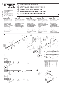
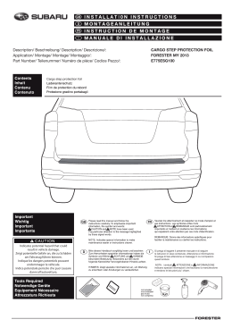
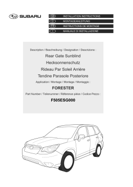
Mehr als Pumpen
LC
Bausatz zu Redline LC
Wandmontage der Elektronik
Montage- und Betriebsanleitung
Seite 5
Redline LC
Pièces détachées pour
le montage mural de l’électronique
Instructions d’installation et d’entretien
Page 10
Redline LC
Set di accessori per il montaggio
a muro dell’elettronica
Istruzioni di installazione e funzionamento
Pagina 15
Redline LC
Construction kit for wall mounting
of the electronics
Installation and Operating Instructions
Page 20
Console voor Redline LC
Wandmontage van elektronica
Montage- en bedrijfsinstructies
Pagina 25
2
Konformitäts-Erklärung
Wir Biral erklären in alleiniger Verantwortung,
dass das Produkt
Redline LC
beschrieben in der beigelegten Dokumentation, mit der
- Richtlinie des Rates 98/37 EG (inkl. Änderungen)
zur Angleichung der Rechtsvorschriften
der EG-Mitgliedstaaten für Maschinen
- Richtlinie des Rates 89/336 (inklusive Änderungen)
zur Angleichung der Rechtsvorschriften
der EG-Mitgliedstaaten für elektromagnetische
Verträglichkeit, EN 50 081-1 und EN 50 082-1
übereinstimmt.
Angewendete harmonisierte Normen
- EN 292
- EN 60335-2-51
Dichiarazione di conformità
Noi, ditta Biral, dichiariamo sotto la nostra
responsabilità assoluta che i prodotti
Redline LC
descritti nella documentazione allegata, sono
conformi alle seguenti direttive:
- Direttiva del Consiglio 98/37 CE (come modificata)
per l’adeguamento delle prescrizioni di legge
degli stati membri della CEE per le macchine
- Direttiva del Consiglio 89/336 (come modificata)
per l’adeguamento delle prescrizioni di legge
degli stati membri della CEE per la compatibilità
elettromagnetica, EN 50 081-1 e EN 50 082-1.
Norme armonizzate applicate
- EN 292
- EN 60335-2-51
Verklaring
Biral verklaart in haar hoedanigheid als fabrikant,
dat de producten
Redline LC
omschreven in bijgaande dokumentatie,
beantwoorden aan:
- Richtlijnen 98/37 EG (zoals laatstelijk gewijzigd)
voor aanpassing van wettelijke voorschriften/
normen van de EG lidstaten voor machines.
- Richtlijnen 89/336 (zoals laatstelijk gewijzigd)
voor aanpassing van wettelijke voorschriften/
normen van de EG lidstaten voor elektromagnetische werking EN 50081-1 en EN 50082-1.
Overige geldende normen:
- EN 292
- EN 60335-2-51
Déclaration de conformité
Nous, l’entreprise Biral, déclarons, sous notre
seule et entière responsabilité, que le produit:
Redline LC
décrit dans la documentation ci-jointe est
conforme aux directives suivantes:
- Directive du Conseil 98/37 CE (modifée) relative
à l’adaptation aux dispositions légales des pays
de l’Union Européenne concernant les machines
- Directive du Conseil 89/336 (modifée) pour
l’adaptation aux dispositions légales des pays
de l’Union Européenne concernant les tolérances
électromagnétiques (EN 50 081-1 et EN 50 082-1).
Normes harmonisées appliquées :
- EN 292
- EN 60335-2-51
Declaration of conformity
We, the Biral Company, taking sole responsibility,
declare that the product
Redline LC
described in the attached documentation,
complies with
- Council Directive 98/37 EC (as amended)
on the harmonisation of the legal regulations
of EU member states for machines
- Council Directive 89/336 (as amended)
on the harmonisation of the legal regulations
of EU member states for electro-magnetic
compatibility, EN 50081-1 and EN 50082-1.
Harmonised standards applied
- EN 292
- EN 60335-2-51
Declaración de conformidad
La empresa Biral declara bajo su exclusiva
responsabilidad que los productos
Redline LC
descritos en la documentación adjunta, son
conformes con la
- Directiva 98/37 CE (incluidas las modificaciones)
del Consejo para Equiparación de Normativas sobre
Maquinaria, de los miembros de la Unión Europea
- Directiva 89/336 (incluidas las modificaciones)
del Consejo para Equiparación de Normativas sobre
Compatibilidad Electromagnética, EN 50081-1
y EN 50082-1, de los miembros de la Unión Europea.
Normas armonizadoras empleadas:
- EN 292
- EN 60335-2-51
Münsingen, 1st July 2005
Biral AG, Südstrasse 10, CH-3110 Münsingen
Tel. +41 (0) 31 720 90 00, Fax +41 (0) 31 720 94 42
e-mail: [email protected], www.biral.ch
Peter Gyger
Technical Director
Hanspeter Balsiger
Quality Manager
3
Montage der Konsole
Montage de la console
Montaggio della mensola
Fitting the console
Montage van console
Abmessungen
Dimensions
Dimensioni
Dimensions
Afmetingen
(mm)
B1
B2
B3
L1
H1
H2
H3
H4
H5
D1
kg
Konsole
Console
Mensola
Console
Console
LC 650
LC 805
LC 1003
210
159
159
235
135
260
111
70
10
Ø 5.5
240
215
135
315
155
300
155
110
10
Ø 5.5
240
215
135
315
190
320
155
110
10
Ø 5.5
deutsch
5
Inhaltsverzeichnis
1.
1.1
1.2
1.3
1.4
1.8
1.9
Sicherheitshinweise
Seite 6
Allgemeines
6
Kennzeichnung von Hinweisen
6
Personalqualifikation und -schulung
6
Gefahren bei Nichtbeachtung
der Sicherheitshinweise
6
Sicherheitsbewusstes Arbeiten
7
Sicherheitshinweise für den Betreiber/Bediener
7
Sicherheisthinweise für Montage-,
Wartungs- und Inspektionsarbeiten
7
Eigenmächtiger Umbau und Ersatzteilherstellung
7
Unzulässige Betriebsweisen
7
2.
Transport/Lagerung
7
3.
3.1
Verwendungszweck
Umgebungstemperatur
8
8
4.
4.1
4.2
4.3
Montage der Konsole
Vorbereitung
Demontage der Elektronik
Montage der Elektronik
8
8
8
9
5.
Elektrischer Anschluss
9
1.5
1.6
1.7
6
deutsch
1. Sicherheitshinweise
1.1 Allgemeines
Diese Montage- und Betriebsanleitung enthält grundlegende
Hinweise, die bei Aufstellung, Betrieb und Wartung zu beachten
sind. Sie ist daher unbedingt vor Montage und Inbetriebnahme
vom Monteur sowie dem zuständigen Fachpersonal/Betreiber
zu lesen. Sie muss ständig am Einsatzort der Anlage verfügbar
sein.
Es sind nicht nur die unter diesem Abschnitt «Sicherheitshinweise» aufgeführten, allgemeinen Sicherheitshinweise zu
beachten, sondern auch die unter den anderen Abschnitten eingefügten, speziellen Sicherheitshinweise.
1.2 Kennzeichnung von Hinweisen
Die in dieser Montage- und Betriebsanleitung
enthaltene Sicherheitshinweise, deren Nichtbeachtung Gefahren für Personen hervorrufen
können, sind mit allgemeinem Gefahrensymbol
«Sicherheitszeichen nach DIN 4844-W9»
besonders gekennzeichnet.
Dieses Symbol steht für Warnung vor
gefährlicher elektrischer Spannung.
«Sicherheitszeichen nach DIN 4844-W8».
Achtung
Dieses Symbol finden Sie bei Sicherheitshinweisen, deren Nichtbeachtung Gefahren für
die Maschine und deren Funktionen hervorrufen
kann.
Direkt an der Anlage angebrachte Hinweise wie zum Beispiel
- Drehrichtungspfeil
- Kennzeichen für Fluidanschlüsse
müssen unbedingt beachtet und in vollständig lesbarem
Zustand gehalten werden.
1.3 Personalqualifikation und -schulung
Das Personal für Montage, Bedienung, Wartung und Inspektion
muss die entsprechende Qualifikation für diese Arbeiten aufweisen. Verantwortungsbereich, Zuständigkeit und die Überwachung des Personals müssen durch den Betreiber genau
geregelt sein.
1.4 Gefahren bei Nichtbeachtung der Sicherheitshinweise
Die Nichtbeachtung der Sicherheitshinweise kann sowohl eine
Gefährdung für Personen als auch für die Umwelt und Anlage zur
Folge haben. Die Nichtbeachtung der Sicherheitshinweise kann
zum Verlust jeglicher Schadenersatzansprüche führen.
7
deutsch
Im einzelnen kann Nichtbeachtung beispielsweise folgende
Gefährdungen nach sich ziehen:
- Versagen wichtiger Funktionen in der Anlage
- Versagen vorgeschriebener Methoden
zur Wartung und Instandhaltung
- Gefährdung von Personen durch elektrische und mechanische
Einwirkungen
1.5 Sicherheitsbewusstes Arbeiten
Die in dieser Montage- und Betriebsanleitung aufgeführten
Sicherheitshinweise, die bestehenden nationalen Vorschriften
zur Unfallverhütung sowie eventuelle interne Arbeits-, Betriebsund Sicherheitsvorschriften des Betreibers, sind zu beachten.
1.6 Sicherheitshinweise für den Betreiber/Bediener
Gefährdungen durch elektrische Energie sind auszuschliessen
(Einzelheiten hierzu siehe zum Beispiel in den Vorschriften des
NIN (CENELEC) und der örtlichen Energieversorgungsunternehmen).
1.7 Sicherheitshinweise für Montage-, Wartungsund Inspektionsarbeiten
Der Betreiber hat dafür zu sorgen, dass alle Montage-,
Wartungs- und Inspektionsarbeiten von autorisiertem und
qualifiziertem Fachpersonal ausgeführt werden, das sich durch
eingehendes Studium der Montage- und Betriebsanleitung ausreichend informiert hat.
Grundsätzlich sind arbeiten an der Anlage nur im Stillstand
durchzuführen.
Unmittelbar nach Abschluss der Arbeiten müssen alle
Sicherheits- und Schutzeinrichtungen wieder angebracht bzw.
in Funktion gesetzt werden.
Vor der Wiederinbetriebnahme sind die im Abschnitt
«Elektrischer Anschluss» aufgeführten Punkte zu beachten.
1.8 Eigenmächtiger Umbau und Ersatzteilherstellung
Umbau oder Veränderungen an Pumpen sind nur nach
Absprache mit dem Hersteller zulässig. Originalersatzteile und
vom Hersteller autorisiertes Zubehör dienen der Sicherheit.
Die Verwendung anderer Teile kann die Haftung für die daraus
entstehenden Folgen aufheben.
1.9 Unzulässige Betriebsweisen
Die Betriebssicherheit der gelieferten Pumpen ist nur bei bestimmungsgemässer Verwendung entsprechend Abschnitt
«Verwendungszweck»
der
Montageund
Betriebsanleitung gewährleistet. Die in den technischen Daten angegebenen Grenzwerte dürfen auf keinen Fall überschritten werden.
2. Transport / Lagerung
Die Pumpen werden vom Werk in einer zweckmässigen
Verpackung geliefert.
Achtung Pumpen mit elektronischen Bauteilen sind gegen
Feuchtigkeit zu schützen.
deutsch
8
3. Verwendungszweck
Konsole zur separaten Wandmontage der Elektronik.
Das Zubehörset enthält:
– 1 Konsole mit 2m Kabel
– 4 Schrauben und Dübel
Die Elektronik ist Standart auf der Pumpe montiert.
3.1 Umgebungstemperatur
– Die zulässige Umgebungstemperatur beträgt
max 40 °C
– Schutzgrad: IP 42
4. Montage der Konsole
Der Mindestabstand zur heissen Pumpe und
Rohrleitungen beträgt 30 cm.
min. 30 cm
Netzanschluss
4.1 Vorbereitung
– Lochabstände aus Tabelle Seite 3 entnehmen
und an der Wand aufzeichnen
– 4 Dübellöcher Ø 8 mm bohren und Dübel
montieren
– Konsole mit 4 Schrauben Ø 5 ×40 mm befestigen
4.2 Demontage der Elektronik
Achtung
Vor jedem Eingriff in den Klemmenkasten muss die Stromversorgung
der Pumpe abgeschaltet werden.
➁
Vorsicht beim Öffnen
des Klemmenkasten-Deckels!
Elektronik kann bis zu 10 Minuten nach
dem Ausschalten des Stromes unter
Spannung sein.
➀
➀
Sicherungsschraube zwischen Elektronik
und Pumpenmotor lösen.
➁
Elektronik in Richtung Motorachse abziehen.
deutsch
9
4.3 Montage der Elektronik
➂
Dichtung
(3.1)
➂
Elektronik waagrecht auf Konsole aufstecken,
dabei auf Führung und Dichtung achten (3.1)
➃
Sicherungsschraube montieren
Steuerung muss auf 3.1 aufliegen.
➃
Anschlusskabel an Pumpenmotor verlegen.
Achtung genügend Abstand zu heissen Teilen!
Stecker in Gegenstück einstecken.
Stecker mit Sicherungsblech fixieren
5. Elektrischer Anschluss
Der elektrische Anschluss muss durch
einen Fachmann in Übereinstimmung
mit den örtlichen Energieversorgungsunternehmen (EVU) vorgenommen
werden.
NIN (CENELEC)-Vorschriften beachten.
Siehe Betriebsanleitung LC
Nr. 08 0283.2011
français
10
Sommaire
1.
1.1
1.2
1.3
1.4
1.8
1.9
Consignes de sécurité
page 11
Généralités
11
Symboles de sécurité utilisés dans la présente notice 11
Qualification et formation du personnel
11
Risques et dangers en cas de non observation
des consignes de sécurité
11
Observation des règles de sécurité
12
Consignes de sécurité à l’intention
de l’utilisateur/de l’opérateur
12
Consignes de sécurité relatives au montage,
à l’entretien et à la révision
12
Modifications et pièces de rechange
12
Conformité d’utilisation
12
2.
Transport et stockage
12
3.
3.1
But d’utilisation
Température de travail
13
13
4.
4.1
4.2
4.3
Montage de la console
Préparation
Démontage de l’électronique
Montage de l’électronique
13
13
13
14
5.
Raccordement électrique
14
1.5
1.6
1.7
11
français
1. Consignes de sécurité
1.1 Généralités
La présente notice de montage et d’utilisation contient des
instructions importantes pour l’installation, l’utilisation et
l’entretien. Avant le montage et la mise en service, le monteur
et l’opérateur/l’utilisateur doivent donc absolument la lire soigneusement. De manière à avoir toujours cette notice à portée de
main, veuillez la ranger à proximité immédiate de la machine.
Observer non seulement les consignes générales de sécurité
mentionnées dans le présent chapitre «Consignes de sécurité»,
mais aussi celles données aux chapitres suivants.
1.2 Symboles de sécurité utilisés dans la présente notice
Les consignes de sécurité dont la non observation met en danger les personnes sont
précédées du symbole “danger!”
selon DIN 4844-W9.
Symbole de mise en garde contre les risques de
nature électrique (symbole selon DIN 4844-W8)
Attention Symbole accompagnant les consignes de
sécurité dont la non observation présente des
risques pour la machine et ses fonctions.
Les indications apposées sur la machine telles que:
- flèche indiquant le sens de rotation
- désignations des raccordements pour les fluides
doivent être strictement observées et toujours propres afin
d’être parfaitement lisibles.
1.3 Qualification et formation du personnel
Les personnes chargées d’installer, de faire fonctionner, d’entretenir et de réviser l’installation doivent justifier de la qualification requise pour ces différentes tâches. Domaines de
responsabilité, compétences et encadrement du personnel
doivent être définis de manière claire et précise par l’utilisateur.
1.4 Risques et dangers en cas de non observation
des consignes de sécurité
La non observation des consignes de sécurité comporte des
risques, non seulement pour les personnes mais aussi pour
l’environnement et l’installation. De plus, elle peut entraîner la
nullité des droits d’indemnisation en cas de dommages.
12
français
La non observation des consignes de sécurité peut par exemple
provoquer:
- Panne dans l’installation de fonction importante
- l’échec des méthodes d’entretien et de maintenance prescrites
- la mise en danger des personnes par des phénomènes de
nature électrique ou mécanique.
1.5 Observation des règles de sécurité
Les consignes de sécurité indiquées dans cette notice, les réglementations nationales de prévention contre les accidents ainsi
que, le cas échéant, les consignes de sécurité internes à l’intention de l’utilisateur, doivent être rigoureusement observées.
1.6 Consignes de sécurité à l’intention de l’utilisateur/
de l’opérateur
Tout risque de nature électrique doit être écarté. A ce sujet
veuillez vous reporter par exemple aux consignes NIN
(CENELEC) ainsi qu’aux consignes prescrites par votre fournisseur en électricité local.
1.7 Consignes de sécurité relatives au montage, à l’entretien
et à la révision
Il incombe à l’utilisateur de veiller à ce que les opérations de
montage, d’entretien et de révision soient effectuées par un
personnel qualifié et autorisé, et ayant lu attentivement les
instructions données dans la présente notice.
D’une manière générale, les interventions sur l’installation ne
doivent être effectuées qu’après avoir mis la dite installation à
l’arrêt et hors tension.
A la fin de chaque intervention, réinstaller/réactiver tous les
organes de sécurité et toutes les protections.
Avant de remettre l’installation en marche, observer les points
indiqués au chapitre «Raccordement électrique».
1.8 Modifications et pièces de rechange
Toute modification ou transformation d’une pompe par l’utilisateur nécessite l’accord préalable du constructeur. Pour votre
propre sécurité, utilisez uniquement des pièces de rechange de
la marque, et les accessoires recommandés par le constructeur.
Nous déclinons toute responsabilité en cas de dommages résultant de l’utilisation d’autres pièces ou accessoires.
1.9 Conformité d’utilisation
La sécurité d’utilisation des pompes livrées n’est garantie que
dans le cas d’une utilisation conforme, telle que spécifiée au
chapitre «But d’utilisation» de la présente notice. Les valeurs
limites indiquées sur la feuille des caractéristiques techniques
ne doivent en aucun cas être dépassées.
2. Transport et stockage
Les pompes quittent notre usine emballées de manière
adéquate pour leur transport.
Attention Les circulateurs possédant des composants
électroniques doivent être protégés de l’humidité.
français
13
3. But d’utilisation
Console pour montage mural séparé de l’électronique.
L’assortiment d’accessoires comprend:
– 1 console avec 2m de câbles
– 4 vis et trous de cheville
L’électronique est montée en standard sur la pompe.
3.1 Température de travail
– la température de travail ambiante ne doit pas
dépasser 40 °C
– degré de protection: IP 42
4. Montage de la console
4.1 Préparation
– suivre les distances des trous sur le tableau
page 3 et les reporter sur le mur
– percer 4 trous d’un Ø de 8 mm et insérer
les chevilles
– fixer la console avec 4 vis d’un Ø 5 ×40 mm
min. 30 cm
4.2 Démontage de l’électronique
Attention Avant chaque intervention dans
le coffret à bornes, toujours couper
l’alimentation électrique du circulateur!
➁
Attention en ouvrant le couvercle du
coffret à bornes! Les composants
électroniques peuvent encore être
sous tension 10 minutes après avoir
coupé le courant.
➀
➀
Dévisser la vis de sécurité entre le coffret et le
moteur de la pompe
➁
Tirer le coffret vers l’avant
français
14
4.3. Montage de l’électronique
➂
Joint
(3.1)
➂
Glisser le coffret à plat sur la console.
Attention au rail de guidage et au joint (3.1)
➃
Placer la vis de sécurité
La commande doit se trouver sur 3.1
➃
Assurer le câble sur le moteur de la pompe.
Attention Maintenir une distance suffisante avec
les pièces chaudes
Brancher le connecteur.
Fixer le connecteur avec la pièce métallique
de sécurité
5. Raccordement électrique
Le raccordement électrique doit être
effectué par un spécialiste.
Respecter la réglementation locale
de votre fournisseur d’électricité local
et les normes NIN (CENELEC).
Voir instructions d’entretien LC
Nr. 08 0283.2011
italiano
15
Indice
1.
1.1
1.2
1.3
1.4
16
16
16
16
1.9
Avvertenze di sicurezza
Pagina
Generalità
Contrassegno delle avvertenze
Qualifica e addestramento del personale
Pericoli in caso di inosservanza
delle avvertenze di sicurezza
Lavoro in conformità alle avvertenze
e norme di sicurezza
Avvertenze di sicurezza per il gestore e l’operatore
Avvertenze di sicurezza per i lavori di montaggio,
manutenzione e ispezione
Modifiche e fabbricazione di parti
di ricambio senza autorizzazione
Usi non consentiti
2.
Trasporto e stoccaggio
17
3.
3.1
Scopo d’uso
Temperatura ambiente
18
18
4.
4.1
4.2
4.3
Montaggio della mensola
Preparazione
Smontaggio dell’elettronica
Montaggio dell’elettronica
18
18
18
19
5.
Allacciamento elettrico
19
1.5
1.6
1.7
1.8
16
17
17
17
17
17
16
italiano
1. Avvertenze di sicurezza
1.1 Generalità
Queste istruzioni per il montaggio e l’uso contengono delle
avvertenze fondamentali di cui va tenuto conto ai fini dell’
installazione, dell’uso e della manutenzione. Esse debbono
quindi essere assolutamente lette dall’installatore e dal personale
specializzato, nonché dal gestore responsabile, prima del
montaggio e della messa in funzione. Dovranno inoltre restare
sempre a disposizione nelle vicinanze dell’impianto.
Non solo dovranno essere rispettate le avvertenze di sicurezza
generali, riportate in questo capitolo e intitolate «Avvertenze di
sicurezza», ma anche le avvertenze di sicurezza particolari
riportate negli altri capitoli.
1.2
Contrassegno delle avvertenze
Le avvertenze di sicurezza contenute in queste
istruzioni per il montaggio e l’uso, tali da
comportare pericolo per la persona in caso di
inosservanza, sono contrassegnate espressamente con il simbolo di pericolo generale
«Simbolo di sicurezza secondo DIN 4844-W9».
Questo simbolo avverte dalla presenza di tensione
elettrica pericolosa.
«Simbolo di sicurezza secondo DIN 4844-W8»
Attenzione Questo simbolo si trova nelle avvertenze di
sicurezza la cui inosservanza può comportare dei
pericoli per la macchina e le sue funzioni.
Le avvertenze applicate direttamente sull’impianto, come ad
esempio:
- freccia per il senso di rotazione
- contrassegno per raccordi fluidi
debbono essere assolutamente rispettate e mantenute perfettamente leggibile.
1.3 Qualifica e addestramento del personale
Il personale responsabile per il montaggio, il comando, la
manutenzione e l’ispezione deve dimostrare di possedere la
qualifica adatta per svolgere questi lavori. L’ambito di responsabilità, le competenze e i compiti di sorveglianza da parte del
personale debbono essere stabiliti chiaramente da parte dell’
esercente.
1.4 Pericoli in caso di inosservanza delle avvertenze
di sicurezza
L’inosservanza delle avvertenze di sicurezza può causare pericolo
alle persone, all’ambiente e all’impianto. L’inosservanza delle
avvertenze di sicurezza può condurre alla perdita di tutti i diritti al
risarcimento di eventuali danni.
17
italiano
In particolare l’inosservanza può provocare, ad esempio, i
seguenti pericoli:
- guasti tali da pregiudicare funzioni importanti per l’impianto
- inefficacia dei metodi prescritti per la manutenzione
- esposizione a pericolo di persone a causa di azioni elettriche
e meccaniche
1.5 Lavoro in conformità alle avvertenze e norme di sicurezza
Debbono essere osservate: le avvertenze di sicurezza riportate
in queste istruzioni per il montaggio e l’uso, le norme nazionali
esistenti riguardo la prevenzione degli infortuni, eventuali
norme interne sul lavoro, l’uso e la sicurezza stabilite dal
gestore.
1.6 Avvertenze di sicurezza per il gestore e l’operatore
Deve essere prevenuto qualsiasi pericolo causato da energia
elettrica (per maggiori particolari vedi ad esempio le norme
della NIN (CENELEC) e delle aziende elettriche locali).
1.7 Avvertenze di sicurezza per i lavori di montaggio,
manutenzione e ispezione.
Il gestore dovrà provvedere a far eseguire tutti i lavori di
montaggio, manutenzione e ispezione da personale autorizzato
e qualificato; tale personale dovrà informarsi adeguatamente
tramite approfondita lettura delle istruzioni di montaggio e di
uso.
Fondamentalmente, i lavori sull’impianto dovranno essere
compiuti solo in stato di macchina ferma e non sotto tensione.
Immediatamente dopo la conclusione dei lavori, si dovranno
nuovamente applicare o mettere in funzione tutti i dispositivi di
sicurezza e di protezione.
Prima della rimessa in funzione si dovrà tener conto dei punti
elencati nel capitolo «Allacciamento elettrico».
1.8 Modifiche e fabbricazione di parti di ricambio
senza autorizzazione
Qualsiasi cambiamento o modifica delle pompe è consentito
solo previa autorizzazione da parte del fabbricante. Le parti di
ricambio originali e gli accessori autorizzati dal fabbricante sono
importanti ai fini della sicurezza.
L’uso di parti estranee e non originali può condurre all’annullamento di ogni responsabilità per le conseguenze derivanti.
1.9 Usi non consentiti
La sicurezza di funzionamento delle pompe fornite è garantita
solo a condizione che esse vengano destinate all’uso espressamente previsto dal costruttore, come da capitolo «Scopo d’uso»
delle istruzioni di montaggio ed uso. I valori limite indicati nei
dati tecnici non debbono essere in alcun caso superati.
2. Trasporto e magazzinaggio
Le pompe escono dallo stabilimento dotate d’imballaggio
adeguato.
Attenzione Le pompe dotate di componenti elettronici devono
essere protette contro l’umidità.
italiano
18
3. Scopo d’uso
Mensola per il montaggio separato a muro
dell’ elettronica.
Il set degli accessori è composto da:
– 1 mensola con 2 m di cavo
– 4 viti e tasselli
Il comando elettronica è normalmente montata
sulla pompa.
3.1 Temperatura ambiente
– La temperatura ambiente consentita non deve
superare i 40 °C
– Grado di protezione: IP 42
4. Montaggio della mensola
La distanza minima, della mensola, dalla pompa
surriscaldata e le tubazioni è di 30 cm.
min. 30 cm
4.1 Preparazione
– Prendere a riferimento le distanze dei fori
che figurano nella tabella a pag. 3 e segnarle
nel muro
– Praticare 4 fori di 8 mm e inserirvi i tasselli
– Fissare la cmensola con 4 viti dal Ø 5 ×40 mm
4.2 Smontaggio dell’elettronica
Attenzione
Prima di iniziare i lavori di manutenzione sulla morsettiera disinserire
l’alimentazione elettrica della pompa
➁
Aprire con cautela il coperchio della
morsettiera. I circuiti elettronici
possono rimanere in tensione fino
a 10 minuti dopo aver staccato il
contatto elettrico
➀
➀
Svitare la vite di sicurezza posta tra l’elettronica
e il motore della pompa.
➁
Estrarre l’elettronica in direzione dell’asse
del motore.
italiano
19
4.3 Montaggio del comando elettronico
➂
Guarnizione
(3.1)
➃
➂
Inserire orizzontalmente l’elettronica nella
mensola facendo attenzione alla guida
e alla guarnizione (3.1).
➃
Fissare la vite di sicurezza
Il comando deve essere posto sopra
la guarnizione (3.1)
Collegare il cavo di allacciamento al motore
della pompa.
Attenzione Il cavo di allacciamento non deve
essere vicino alle parti surriscaldate
Inserire la presa nella spina
Fissare la presa con la piastrina di sicurezza.
5. Allacciamento elettrico
L’allacciamento elettrico deve essere
eseguito da personale qualificato.
Si devono rispettare le norme delle
aziende elettriche locali e le norme
NIN (CENELEC).
Vedi istruzioni per l’uso LC
Nr. 08 0283.2011
english
20
Contents
1.
1.1
1.2
1.3
1.4
1.8
1.9
Safety information
Page 21
General remarks
21
Identification of notices
21
Staff qualification and training
21
Risk in the event of non-compliance
with the safety information
Safety-conscious work
22
Safety information
for the operator/operating personnel
22
Safety information for installation,
maintenance and inspection works
22
Unauthorised reconstruction and production of spares 22
Improper operating modes
22
2.
Transport/Storage
22
3.
3.1
Intended purpose
Ambient temperature
23
23
4.
4.1
4.2
4.3
Fitting the console
Preparation
Dismantling the electronics
Assembling the electronics
23
23
23
24
5.
Electrical connection
24
1.5
1.6
1.7
21
english
1. Safety information
1.1 General remarks
These installation and operating instructions contain items of
information of fundamental importance which must be taken
into account during assembly, operation and maintenance.
They should therefore be read carefully before installation and
setting up the pump by the fitter and also by the responsible
specialist staff/operator. They must always be available for
consultation at the plant’s place of deployment.
Not only the general safety hints included in this «Safety Hints»
section are to be observed, but also the special items of safety
information included in the other sections.
1.2 Identification of notices
The safety information contained in these installation and operating instructions are specially
marked with the general danger symbol «Safety
sign according to DIN 4844-W9». The noncompliance of it can lead to danger to people.
This symbol is a warning of dangerous electric
voltage.
«Safety sign according to DIN 4844-W8».
Warning
You will find this symbol beside the safety
information. The non-compliance of it can
endanger the machine and its functions.
Information signs mounted directly on the plant, such as, for
example
- arrow for direction of rotation
- symbols for fluid connections
must carefully be minded and be kept in a fully legible state.
1.3 Staff qualification and training
The staff deployed for assembly, operating, maintenance and
inspection tasks must have the appropriate qualifications for
such work. The scope of responsibility, competence and supervision of the staff must be controlled exactly by the operator.
1.4 Risks in the event of non-compliance
with the safety information
Non-compliance with the safety information can result in
the danger to persons and the plant and the environment.
Non-compliance with the safety information can lead to the loss
of claims for damages of any kind.
22
english
In detail, non-compliance, for example, may result in the
following risks:
- failure of important functions in the plant
- failure of prescribed methods for servicing and maintenance
- danger to persons through electrical and mechanical causes
1.5 Safety-conscious work
The safety information contained in these installation and
operating instructions, the existing national regulations for the
prevention of accidents, as well as any internal working,
operating and safety regulations stipulated by the operator
must be observed.
1.6 Safety information for the operator/operating personnel
Any risks from electric power must be eliminated (For details
see, for example, the regulations published by NIN (CENELEC)
and the I.E.E.).
1.7 Safety information for installation, maintenance
and inspection works
The operator has to ensure that all installation, maintenance
and inspection works are carried out by authorised and qualified
personnel who have informed themselves adequately the
requirements by a thorough study of the installation and
operating instructions.
Basically, any works on the plant should only be carried out
when it is at standstill and not carrying any electrical current.
Directly after completion of the works, all safety and protective
installations must be mounted or activated again.
Before re-commissioning, the points listed in the section
«Electrical connection» must be observed.
1.8 Unauthorised reconstruction and production of spares
Reconstruction of or changes to pumps are only permissible
after consultation with the manufacturer. Genuine spare parts
and accessories authorised by the manufacturer serve the cause
of safety.
The use of other parts can cancel any liability for the resultant
consequences of this.
1.9 Improper operating methods
The operating reliability of the pumps supplied is only
guaranteed with appropriate application of the section
«Intended application» of the Installation and Operating
Instructions. The limit values given in the technical data must
not be exceeded on any account.
2. Transport/Storage
The pumps are supplied from the factory
in appropriate packing.
english
23
3. Intended purpose
Console for the separate wall mounting
of the electronics.
The accessories set contains:
– 1 console with 2m cable
– 4 screws and dowels
The electronics is normally mounted on the pump:
3.1 Ambient temperature
– The permissible ambient temperature is max. 40 °C
– Protection class: IP42
4. Fitting the console
The minimum distance from the hot pump
and pipes is 30 cm.
min. 30 cm
4.1 Preparation
– For hole spacings see table on page 3
and mark on wall accordingly.
– Drill 4 Ø 8 mm holes for dowels and fit dowels.
– Fasten console with 4 Ø 5× 40 mm screws.
4.2 Dismantling the electronics
Warning
Before every intervention
in the terminal box, the power supply
to the pump must be switched off.
➁
Take care when opening the terminal
box cover. The electronics can still
have dangerous voltages for up to
10 minutes after the current has been
switched off.
➀
➀
Loosen the securing screw between
the electronics and pump motor.
➁
Pull away the electronics towards
the motor axis.
english
24
4.3 Fitting the electronics
➂
Seal
(3.1)
➂
Mount the electronics horizontally on the console paying attention to the guide and seal (3.1).
➃
Fit securing screw.
Control unit must lie on 3.1.
➃
Lay connecting cable to pump motor.
Warning Leave sufficient space from hot parts
Insert plug in counterpart.
Fix plug with securing plate.
5. Electrical connection
Electrical connection must be made
by an expert electrician in compliance
with local power supply company
regulations (EVU).
Please observe NIN (CENELEC)
regulations.
See operating instructions LC
No. 08 0283.2011
nederlands
25
Inhoud
1.
1.1
1.2
1.3
1.4
26
26
26
26
1.8
1.9
Veiligheidsinstructies
pagina
Algemeen
Verklaring van de symbolen
Gekwalificeerd personeel en opleiding
Gevaar bij niet opvolgen
van veiligheidsinstructies
Uitvoering volgens veiligheidsnormen
Veiligheidsinstructies voor uitvoerder/gebruiker
Veiligheidsinstructies voor montage-,
onderhouds- en inspectiewerkzaamheden
Aanpassingen en reserveonderdelen
Andere toepassingen/gebruik
2.
Transport/opslag
27
3.
3.1
Toepassing
Omgevingstemperatuur
27
27
4.
4.1
4.2
4.3
Montage van console
Voorbereiding
Demontage van elektronica
Montage van elektronica
27
27
27
28
5.
Elektrische aansluiting
29
1.5
1.6
1.7
26
27
27
27
27
27
26
nederlands
1. Veiligheidsinstructies
1.1 Algemeen
Deze montage- en bedrijfshandleiding bevat belangrijke
aanwijzigingen die bij montage, bedrijf en onderhoud
opgevolgd moeten worden. Deze moeten voor montage en
inbedrijfname, door zowel monteur als verantwoordelijke
technicus/gebruiker, volledig gelezen worden. Deze handleiding
moet altijd bij de installatie aanwezig zijn. Extra aandacht voor
de onder «veiligheidsinstructies» (hoofdstuk 1) opgenomen
algemene veiligheidsinstructies, als ook in de andere hoofdstukken omschreven speciale veiligheidsinstructies.
1.2
Verklaring van de symbolen
Veiligheidsinstructies, die met niet, of onjuist
opvolgen, gevaar voor mensen kunnen opleveren
zijn in deze montage- en bedrijfshandleiding
aangegeven met het «algemene gevarensymbool, volgens DIN 4844-W9».
Dit symbool betekent waarschuwing voor gevaarlijke elektrische spanning. «Veiligheidssymbool
volgens DIN 4844-W8».
Pas op
Dit symbool treft u aan bij veiligheidsinstructies
die bij niet of onjuist opvolgen gevaar (schade)
voor de pomp/installatie en de werking ervan
kunnen opleveren.
Op de pomp/installatie aangebrachte instructie zoals
bijvoorbeeld:
- draairichtingsaanduiding
- aanduiding voor leidingaansluitingen moeten opgevolgd en
altijd volledig leesbaar blijven.
1.3 Gekwalificeerd personeel en opleiding
Personeel, verantwoordelijk voor de montage, bediening,
onderhoud en inspektie moet hiervoor gekwalificeerd zijn.
Verantwoordelijkheden/bevoegdheden en de controle van
personeel moet door de uitvoerder/gebruiker nauwkeurig
bepaald zijn.
1.4 Gevaar bij niet opvolgen van veiligheidsinstructies
Niet opvolgen van de veiligheidsinstructies kan gevaar voor
mensen, omgeving, milieu en pomp/installatie opleveren.
Bij niet opvolgen van de veiligheidsinstructies vervalt elke vorm
van aansprakelijkheid.
27
nederlands
In sommige gevallen kan dit bijvoorbeeld leiden tot:
- het niet functioneren van belangrijke onderdelen
- storing in werking van pomp/installatie
- storing in besturing, bedrijfs- en storingsmelding
- gevaar voor mensen door elektrische en mechanische
invloeden
1.5 Uitvoering volgens veiligheidsnormen
Vermelde veiligheidsinstructies, technische normen, en ter
plaatse geldende (veiligheids)voorschriften en (veiligheids)
normen ter voorkoming van ongevallen en de eventuele geldende richtlijnen voor werk, uitvoering, bedrijfsvoering moeten
in acht genomen worden.
1.6 Veiligheidsinstructies voor uitvoerder/gebruiker
Gevaar ten gevolge van elektrische spanning moet voorkomen
worden (voor details wordt verwezen naar de voorschriften van
het plaatselijk energiebedrijf).
1.7 Veiligheidsinstructies voor montage-, onderhouds- en
inspectiewerkzaamheden
De uitvoerder/gebruiker is verantwoordelijk dat alle montageonderhouds- en inspectiewerkzaamheden door geautoriseerd
en gekwalificeerd personeel geschied. Deze stellen zich op de
hoogte van montage- en bedrijfshandleiding. Werk aan de
installatie is alleen bij stilstand en spanningsloze toestand
toegestaan.
Direkt na het beëindigen van de werkzaamheden moeten alle
veiligheids- en beschermingsmaatregelen weer in orde
gebracht worden. Voor opnieuw ingebruik nemen wordt verwezen naar hoofdstuk «elektrische aansluiting».
1.8 Aanpassingen en reserveonderdelen
Aanpassingen en veranderingen aan pompen/installatie zijn
alleen na overleg met fabrikant toegestaan. Alleen originele
reserveonderdelen en door fabrikant geaccepteerde onderdelen
mogen toegepast worden.
Bij toepassing van andere onderdelen vervalt elke vorm van
aansprakelijkheid en is de fabrikant evenmin aansprakelijk voor
de gevolgen daarvan.
1.9 Andere toepassingen/gebruik
De bedrijfszekerheid van de pompen/installatie geldt alleen bij
juiste toepassing (hoofdstuk «toepassing») van de montage- en
bedrijfshandleiding. De in de technische specificatie aangegeven maximum waarden mogen in geen geval overschreden
worden.
2. Transport/opslag
De pompen/installaties worden door de fabriek met verpakking
geleverd, uitsluitend geschikt voor transport/opslag.
Pas op
Pompen met elektronica moeten tegen vocht
beschermd worden.
nederlands
28
3. Toepassing
Console voor separate montage van elektronica.
De set omvat:
– 1 console met 2m kabel
– 4 schroeven en pluggen
De elektronica is standaard op de pomp gemonteerd.
3.1 Omgevingstemperatuur
– De toelaatbare omgevingstemperatuur bedraagt
max. 40 °C
– Bescherming: IP 42
4. Montage van console
De afstand tussen de pomp en console moet
minimaal 30 cm zijn.
min. 30 cm
4.1 Voorbereiding
– boorgaten volgens tabel pagina 3
op de montageplaats aftekenen.
– 4 gaten Ø 8 mm boren en pluggen plaatsen.
– console met 4 schroeven Ø 5 ×40 mm monteren.
4.2 Demontage van elektronica
Pas op
➁
Voor elke ingreep in klemmenkast
voeding van de pomp uitschakelen.
Voorzichtig bij het openen van deksel
elektronica. De elektronica kan nog
10 minuten na het uitschakelen van
de voeding onder spanning staan.
➀
➀
Borgschroef tussen elektronica en pompmotor
verwijderen.
➁
Elektronica evenwijdig aan motoras demonteren.
nederlands
29
4.3 Montage van elektronica
➂
Afdichting
(3.1)
➃
➂
De elektronica op de console schuiven, let op de
afdichting (3.1)
➃
Elektronica goed in console aandrukken.
Borgschroef aanbrengen.
➄
Bij LC 650 massakabel monteren
Aansluitkabel op pompmotor aansluiten.
Pas op
voldoende afstand tot warme delen.
Steker insteken.
Steker met borgplaat fixeren.
5. Elektrische aansluiting
De elektrische aansluiting moet door
een gekwalificeerd elektriciën uitge
voerd worden. De aansluiting moet
conform de nEN 1010 en de plaatselijke
voorschriften geschieden.
Zie bedrijfsinstructies LC
Nr. 08 0283.2011
Biral AG
Südstrasse 10
CH-3110 Münsingen
Tel. +41 (0) 31 720 90 00
Fax +41 (0) 31 720 94 43
E-Mail:[email protected]
www.biral.ch
Biral GmbH
Präzisionspumpen
Freiherr-vom-Stein-Weg 15
D-72108 Rottenburg am Neckar
Tel. +49 (0) 7472 16 33 0
Fax +49 (0) 7472 16 34 0
E-Mail:[email protected]
www.biral.de
Biral Pompen B.V.
Printerweg 13 3821 AP
Postbus 2650 3800 GE
NL-Amersfoort
Tel. +31 (0) 33 455 94 44
Fax +31 (0) 33 455 96 10
E-Mail:[email protected]
www.biral.nl
04/07 08 0285.2011 - Printed in Switzerland
Biral AG Münsingen, Hauptsitz Schweiz
Generalvertreter Schweiz:
Hoval Herzog AG
CH-8706 Feldmeilen
Tel. +41 (0) 1 925 61 11
Fax +41 (0) 1 923 11 39
Scarica