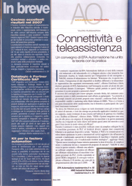
MBC/MBD/MBP/MBEC/MBEI/MBEP/MBU - Mosaic fieldbus modules MOSAIC MODULI BUS DI CAMPO INTRODUZIONE Il presente foglio tecnico illustra il funzionamento dei moduli BUS della serie MOSAIC: MBP (PROFIBUS DP-V1); MBD (DeviceNet); MBC (CANOpen), MBEC (ETHERCAT); (ETHERNET/IP); MBEP (PROFINET), MBU (USB). MBEI COLLEGAMENTI ELETTRICI Collocare i moduli in un ambiente con grado di protezione almeno IP54. I moduli devono essere alimentati con tensione di alimentazione 24Vdc 20% (PELV, conforme alla EN 60204-1 (Capitolo 6.4)). Non utilizzare MOSAIC come alimentazione per dispositivi esterni. La connessione di massa (0VDC) deve essere comune a tutti i componenti del sistema. Ogni modulo è fornito di quattro connettori (Figura 1): 1) Connettore a 5 vie MSC --> verso il sistema MOSAIC 2) Connettore USB miniB --> verso un PC 3) Connettore BUS --> verso il BUS di campo (non presente su MBU) 4) Morsettiera frontale --> alimentazione COLLEGAMENTI MORSETTIERA (LATO A - SUPERIORE) MORSETTO SEGNALE 1 +24VDC + 20% 2 3 4 GND Tabella 1 Figura 1 8540801 • 09/05/2012 • Rev.8 1 MBC/MBD/MBP/MBEC/MBEI/MBEP/MBU - Mosaic fieldbus modules COMPOSIZIONE PACCHETTO DATI PROTOCOLLO Il modulo bus esporta lo stato del sistema e stato e diagnostica di tutti gli I/O configurati sul Mosaic e permette di importare 8 singoli ingressi dal fieldbus. Le mappe di memoria in input e in output sono rappresentate nelle tabelle di pagina 3. La mappa in input è composta da un solo byte che rappresenta gli ingressi fieldbus. La mappa in output è composta da un byte di stato, un numero di byte variabile per rappresentare lo stato degli ingressi del Mosaic, un byte che rappresenta la copia degli ingressi fieldbus, un numero di byte variabile per rappresentare i probe, un numero variabile di byte per rappresentare lo stato delle OSSD del Mosaic, due byte per rappresentare la diagnostica del Mosaic. Lo stato del sistema è rappresentato con 1 byte il cui bit 0 indica se il Mosaic è online/offline e il bit 1 segnala la presenza di eventuale diagnostica. Ogni ingresso e ogni uscita (OSSD) configurata sul sistema hanno due informazioni associate: uno stato e una diagnostica. Lo stato è un valore binario, 0 o 1, la diagnostica è un codice che indica la situazione dell'I/O, può essere OK o contenere l'indicazione di un problema sull'I/O stesso. Ogni modulo con ingressi ha un numero di bit corrispondenti al numero di ingressi fisici presenti, quindi i moduli M1, MI8, MI8O2 hanno associato 1 byte (8 bit), il modulo MI16, MI12T8 2 byte (16 bit) per lo stato degli ingressi. La posizione dei byte relativi agli ingressi dipende dal tipo di moduli installati secondo l’ordine seguente: M1, MI8O2, MI16, MI8, MI12T8. In caso siano installati più moduli dello stesso tipo l’ordine segue il numero di nodo. Le uscite di sicurezza sono rappresentate con 1 o 2 byte. L'eventuale diagnostica è rappresentata con 2 byte sui quali è presentato il numero dell'I/O con il problema e il valore della diagnostica, nel caso sia presente più di una diagnostica i valori si alternano ogni 500 ms. Ogni gruppo di informazioni: stato degli ingressi, diagnostica degli ingressi, stato degli ingressi fieldbus, stato dei probe, stato delle uscite di sicurezza, diagnostica delle uscite di sicurezza può essere abilitato/disabilitato permettendo il controllo delle informazioni e di conseguenza del numero di byte esportati sul fieldbus. Gli ingressi fieldbus sono 8 bit indipendenti tramite i quali è possibile iniettare nello schema elettrico 8 diversi stati. Il byte che rappresenta gli 8 ingressi fieldbus è mappato come primo byte in input. Nei fieldbus in cui la posizione è importante (es. PROFIBUS) il byte in input deve essere mappato prima dei byte in output. Per i fieldbus basati su CANOpen l’accesso ai dati è fornito via pdo. Non è possibile leggere i dati via sdo. 8540801 • 09/05/2012 • Rev.8 2 MBC/MBD/MBP/MBEC/MBEI/MBEP/MBU - Mosaic fieldbus modules La seguente tabella descrive la mappa dei byte in output sul PLC: (1 byte) B1 B0 STATUS SISTEMA B0=1: Mosaic online / B1=1: Diagnostica presente Ingressi Minimo: 1 byte Massimo: 16 byte Ingressi fieldbus Probe OSSD Minimo: 1 byte Massimo: 2 byte Indice I/O DIAGNOSTICA (2 byte) vedi: Tabella 4 - Tabella 5 - Tabella 6 Codice diagnostica La seguente tabella descrive la mappa del byte in input sul PLC: B7 B6 B5 B4 B3 B2 B1 B0 Ingressi fieldbus Nel caso sia presente un modulo fieldbus (MBP, MBC o MBD) nel sistema Mosaic, MSDesigner includerà nel report una tabella con l'Indice I/O relativo a tutti gli ingressi, gli ingressi fieldbus, i probe e le uscite di sicurezza presenti nello schema elettrico. 8540801 • 09/05/2012 • Rev.8 3 MBC/MBD/MBP/MBEC/MBEI/MBEP/MBU - Mosaic fieldbus modules DIAGNOSTICA Ogni ingresso e ogni uscita di sicurezza ha un codice di diagnostica associato. Quando l’I/O è connesso correttamente il codice diagnostica è OK e non viene esportato sul fieldbus; quando l’I/O ha un problema, il sistema esporta sul fieldbus 2 byte con: - l’indice dell’I/O in questione - il codice di diagnostica associato Il campo "Indice I/O" Tale campo indica il numero che identifica l'I/O che presenta diagnostica diversa da OK. I valori possibili per il campo sono indicati in Tabella 2. TIPO DI SEGNALE Ingresso Uscita INDICE I/O 1-128 192-255 Tabella 2 8540801 • 09/05/2012 • Rev.8 4 MBC/MBD/MBP/MBEC/MBEI/MBEP/MBU - Mosaic fieldbus modules Il campo "Codice diagnostica" Il campo "Codice diagnostica" indica la diagnostica relativa all’I/O. I valori possibili per il campo sono indicati nelle tabelle 4, 5 e 6. Diagnostica ingressi 128 (0x80) Diagnostica ingressi OK 1 Non passato da zero I due contatti non sono tornati entrambi in posizione di riposo 2 Contemporaneità fallita I due contatti non si chiudono contemporaneamente 3 Contemporaneità fallita mano 1 Connessione errata di un lato di un comando a due mani 4 Contemporaneità fallita mano 2 Connessione errata di un lato di un comando a due mani 7 Selettore incoerente Il selettore non può avere più di un ingresso attivo 8 Selettore sconnesso Il selettore non può avere nessun ingresso attivo 10 Errore OUT_TEST Segnala la presenza di diagnostica su un OUT_TEST collegato all'ingresso 11 Secondo ingresso KO Controllo di ridondanza fallito sull'ingresso 12 Diagnostica OUT_TEST OK 13 Uscita connessa ad altri ingressi L'uscita di test non è connessa all'ingresso configurato 14 Uscita OK ma ingresso collegato a 24V Ingresso bloccato 15 Corto tra test fotocellula e input fotocellula Il tempo di risposta della fotocellula è troppo basso 16 Fotocellula non risponde Il segnale di test sul proiettore non è presente sul ricevitore della fotocellula 17 Corto tra fotocellule Il segnale di test è presente su due fotocellule diverse 18 Tappeto sconnesso Una delle due connessioni del tappeto non è corretta 19 Uscita non congruente ai feedback Il segnale di test applicato all'ingresso è presente su più di un OUT_TEST 20 Connessione errata Il segnale di test è presente su più di un ingresso 21 Uscita stucked Il segnale di test applicato all'ingresso non è presente sull'OUT_TEST 22 Secondo OUT_TEST KO Controllo di ridondanza fallito sull'OUT_TEST 133 (0x85) 1 Contemporaneità due mani fallita Il comando a due mani deve essere premuto contemporaneamente 134 (0x86) 2 Mai avviato Ingresso con test all'avvio fallito 137 (0x89) 3 Attesa restart Non è stato attivato il reset su un ingresso con reset manuale Tabella 3 Diagnostica OSSD 0 1 2 3 4 Diagnostica OSSD OK Enable mancante Attesa restart OSSD Feedback K1/K2 mancante Attesa altro micro Controllo di ridondanza fallito sull'OSSD Tabella 4 1 2 3 Se più di un I/O ha diagnostica la coppia Indice I/O e codice diagnostica è inviata a rotazione ogni 500ms. Le diagnostiche 133, 134 e 137 non prevedono segnalazione di errore visiva sui led del Mosaic. Le diagnostiche 133, 134 e 137 non prevedono segnalazione di errore visiva sui led del Mosaic. Le diagnostiche 133, 134 e 137 non prevedono segnalazione di errore visiva sui led del Mosaic. 8540801 • 09/05/2012 • Rev.8 5 MBC/MBD/MBP/MBEC/MBEI/MBEP/MBU - Mosaic fieldbus modules SEGNALAZIONI MBC MBD MBP MBEC MBEI MBEP MBU Figura 2 LED SIGNIFICATO ON RUN IN FAIL EXT FAIL LED1 LED2 VERDE VERDE ROSSO ROSSO ROSSO/VERDE ROSSO/VERDE Accensione - TEST iniziale ON ON ON ON ON ON In attesa di configurazione da M1 ON lampeggiante OFF OFF OFF OFF Ricevuta configurazione da M1 ON ON OFF OFF vedere tabelle singoli moduli Tabella 5 - Visualizzazione iniziale/dinamica MODULO MBC LED OPR LED ERR STATO INDICAZIONE STATO INDICAZIONE Verde OPERATIONAL stato OPERATIONAL DESCRIZIONE OFF - Verde lampeggiante lento PREOPERATIONAL stato PRE-OPERATIONAL Rosso 1 lampeggio Raggiunto limite di attenzione Verde 1 lampeggio STOPPED stato STOPPED Rosso lampeggiante veloce LSS Verde lampeggiante veloce Autobaud Rilevazione Baudrate Rosso 2 lampeggi Controllo eventi Rilevato Node Guarding (NMT master o slave) o Heartbeat (Consumer) Rosso EXCEPTION Rosso Caduto il BUS BUS non funzionante stato EXCEPTION DESCRIZIONE funzionamento normale Un contatote di errori del bus ha raggiunto il livello di attenzione Servizio LSS operativo Tabella 6 8540801 • 09/05/2012 • Rev.8 6 MBC/MBD/MBP/MBEC/MBEI/MBEP/MBU - Mosaic fieldbus modules MODULO MBD LED NET LED STS STATO INDICAZIONE DESCRIZIONE STATO INDICAZIONE Verde On-line connesso Verde Funzionamento normale Verde lampeggiante (1Hz) On-line non connesso Verde lampeggiante (1Hz) In attesa Configurazione incompleta, MBD attende attivazione Rosso Errore di critico di connessione MBD incapace di comunicare Rosso Errore fatale Rilevato uno o più errori non recuperabili Rosso lampeggiante (1Hz) Time-out di una o più connessioni Uno o pù dispositivi di I/O sono in time-out Rosso lampeggiante (1Hz) Errore Rilevato uno o più errori recuperabili Verde/Rosso alternati TEST MBD in Test Verde/Rosso alternati TEST MBD in Test Stabilita 1 o più connessioni Nessuna connessione stabilita DESCRIZIONE Tabella 7 MODULO MBP LED MODE LED STS STATO INDICAZIONE DESCRIZIONE Verde On-line scambio dati Verde lampeggiante On-line CLEAR Rosso lampeggiante (1 lampeggio) Errore parametrizzazione Rosso lampeggiante (2 lampeggi) Errore di configurazione PROFIBUS rif. IEC 61158-6 STATO INDICAZIONE OFF MBP non inizializzato Verde Inizializzato Verde lampeggiante Inizializzato con diagnostica attiva Rosso Exception error dati di configurazione MASTER o MBP errati DESCRIZIONE Stato SETUP o NW_INIT Terminata la fase di inizializzazione NW_INIT Bit di EXTENDED DIAGNOSTIC settato stato di EXCEPTION Tabella 8 MODULO MBEC LED STS LED ERR STATO INDICAZIONE DESCRIZIONE STATO INDICAZIONE OFF INIT OFF Nessun errore Verde OPERATIONAL Stato OPERATIONAL Verde lampeggiante PREOPERATIONAL Stato PREOPERATIONAL Rosso 2 lampeggi Timeout watchdog Verde 1 lampeggio SAFEOPERATIONAL Stato SAFEOPERATIONAL Rosso Avaria controller Rosso (Fatal Event) Sistema in blocco - - INIT o no power Rosso lampeggiante DESCRIZIONE Nessun errore o no power Configurazione non Cambio stato richiesto dal master non possibile. valida Timeout watchdog synch manager Modulo Anybus in EXCEPTION - Tabella 9 MODULO MBEI LED NET LED STS STATO INDICAZIONE / DESCRIZIONE STATO INDICAZIONE DESCRIZIONE OFF No power o no indirizzo IP OFF No power - Verde On-line,conesso Verde Stato RUN - Verde lampeggiante On-line, non connesso Verde lampeggiante Non configurato - Rosso Indirizzo IP duplicato Rosso Errore fatale Rilevato uno o più errori non recuperabili Time-out conessione Rosso lampeggiante Errore Rilevato uno o più errori recuperabili Rosso lampeggiante Tabella 10 8540801 • 09/05/2012 • Rev.8 7 MBC/MBD/MBP/MBEC/MBEI/MBEP/MBU - Mosaic fieldbus modules MODULO MBEP LED NET STATO LED STS INDICAZIONE DESCRIZIONE STATO INDICAZIONE OFF Offline No power Connessione con Controller IO non presente DESCRIZIONE OFF Non inizializzato Verde Online (Run) Stabilita connessione con il Controller IO Controller IO in RUN Verde Funzionamento normale Verde lampeggiante Online (stop) Stabilita connessione con il Controller IO Controller IO in STOP Verde 1 lampeggio Evento(i) diagnostica Verde 2 lampeggi Blink Rosso Eccezione Usato per identificare il nodo nella rete Rosso 1 lampeggio Errore di configurazione Rosso 2 lampeggi Errore indirizzo IP Rosso 3 lampeggi Errore station name Rosso 4 lampeggi Errore interno Modulo in stato EXCEPTION Errore identificazione Indirisso IP non configurato Station name non configurato Tabella 11 MODULO MBU LED CONNECT STATO INDICAZIONE DESCRIZIONE Verde USB connected Modulo collegato al Pc tramite USB Spento USB not connected Modulo non collegato Tabella 12 DIAGNOSI GUASTI LED SIGNIFICATO ON RUN IN FAIL EXT FAIL LED1 LED2 VERDE VERDE ROSSO ROSSO ROSSO/VERDE ROSSO/VERDE Guasto interno microcontrollore ON OFF 2 lampeggi* OFF Guasto interno scheda ON OFF 3 lampeggi* OFF Errore di configurazione ON OFF 5 lampeggi* OFF Errore comunicazione BUS ON OFF 5 lampeggi* OFF Interruzione comunicazione BUS ON OFF ON OFF Rilevato un modulo identico ON OFF 5 lampeggi* 5 lampeggi vedere tabelle singoli moduli Tabella 13 * La frequenza di lampeggio dei led è ON per 300ms e OFF per 400ms, con intervallo tra due sequenze di 1s. 8540801 • 09/05/2012 • Rev.8 8 MBC/MBD/MBP/MBEC/MBEI/MBEP/MBU - Mosaic fieldbus modules ESEMPI DI DIAGNOSTICA Esempio 1 Nell’esempio in Figura 3 l’ingresso Input 1 (connesso al modulo M1) è testato con il segnale di test M1-T1. In fase di cablaggio sull’ingresso 1 viene erroneamente connesso il 24Vdc invece del segnale di test M1-T1. - I campi Indice I/O e Codice diagnostica assumeranno i seguenti valori: 1 - 20 per indicare la diagnostica sull’ingresso 1 del modulo M1 (Connessione errata). Figura 3 Esempio 2 In questo esempio si nota come l'Indice I/O non corrisponda al morsetto fisico sul modulo M1, ma al blocco logico. In Figura 4 ad esempio l’elemento a due mani collegato ai morsetti fisici Input 1 e Input 2 corrisponde all'Indice I/O n°1 e l'arresto di emergenza collegato ai morsetti Input 3 e Input 4 corrisponde all'Indice I/O n°2. indice I/O n°1 indice I/O n°2 Figura 4 8540801 • 09/05/2012 • Rev.8 9 MBC/MBD/MBP/MBEC/MBEI/MBEP/MBU - Mosaic fieldbus modules Esempio 3 L’esempio in Figura 5 è simile all’esempio 1, ma in questo caso l’ingresso Input1 è connesso al modulo MI16 ed è testato con il segnale di test MI16-T1. In fase di cablaggio sull’ingresso 1 viene erroneamente connesso il 24Vdc invece del segnale di test MI16-T1. L’ingresso 1 presenterà il codice di diagnostica 20 (Connessione errata). - I campi Indice I/O e Codice diagnostica assumeranno i seguenti valori: 1 - 20 per indicare la diagnostica sull’ingresso 1 del modulo MI16. Figura 5 L’OSSD 1 nell’esempio in Figura 6 ha il reset manuale abilitato. Il pulsante collegato all’ingresso 1 viene premuto senza che sia stato dato il reset. - I campi Indice I/O e Codice diagnostica assumeranno i seguenti valori: 192 - 2 per indicare la diagnostica sull’OSSD 1A/1B (Figura 6: 192 = prima uscita). per indicare il codice di diagnostica (Tabella 4: 2 = Attesa restart OSSD). Figura 6 8540801 • 09/05/2012 • Rev.8 10 MBC/MBD/MBP/MBEC/MBEI/MBEP/MBU - Mosaic fieldbus modules BUS CONFIGURATOR USER INTERFACE Il modulo bus viene configurato tramite l’interfaccia USB miniB presente sul pannello frontale e utilizzando il SW "BUS CONFIGURATOR" residente sul CDROM MSDESIGNER. Il presente sw consente la configurazione/comunicazione del sistema MOSAIC con un Pc (utilizzando un modulo MBU) oppure la visualizzazione dei dati trasmessi su bus (attraverso la connessione con la porta USB di un modulo bus). Il seguente schema aiuta a comprendere le possibili connessioni: ESEMPI DI CONNESSIONE M1 MBx (bus) M1 MBU (USB) È importante far rilevare la differenza di comportamento del BUS CONFIGURATOR nel caso di comunicazione con un modulo MBx o con un modulo MBU: MODULO MBx: IL SOFTWARE CONSENTE LA SOLA VISUALIZZAZIONE DEI DATI CHE VIAGGIANO NEL BUS. MUDULO MBU: IL SOFTWARE CONSENTE IL PASSAGGIO DEI DATI IN MODO BIDIREZIONALE MBU PC; (in questo caso il programmatore puo impostare i Fieldbus Input direttamente dal computer). I parametri sui quali è possibile intervenire sono i gruppi di informazioni da spedire, gli eventuali I/O modulari, i virtual input, l’indirizzo del modulo nella rete fieldbus e, nei moduli che lo prevedono, il baudrate. Il range del campo indirizzo dipende dal tipo di fieldbus installato. 8540801 • 09/05/2012 • Rev.8 11 MBC/MBD/MBP/MBEC/MBEI/MBEP/MBU - Mosaic fieldbus modules L’interfaccia grafica La configurazione del modulo deve essere effettuata con sistema disattivato (uscite OFF). La configurazione del modulo può essere interrogata in qualsiasi momento durante il funzionamento del modulo stesso. Per configurare il modulo MBx effettuare i seguenti passi: 1. alimentare il modulo con tensione pari a 24VDC +20% attraverso la morsettiera; 2. collegare il cavo USB al PC e al modulo MBx (o MBU); 3. cliccare sull'icona "BUS CONFIGURATOR – USER INTERFACE" sul desktop. Compare sullo schermo la finestra di configurazione raffigurata a fianco (Figura 7). Figura 7 4. Premere il pulsante “CONNECT”. Il programma riconosce che un modulo bus è connesso (Figura 8); viene riportato il modello di fieldbus, la sua versione del firmware e la condizione del Master M1: verde=M1 attivo (RUN); rosso=M1 non attivo (es. in comunicazione con il Designer). 8540801 • 09/05/2012 • Rev.8 Figura 8 12 MBC/MBD/MBP/MBEC/MBEI/MBEP/MBU - Mosaic fieldbus modules Dopo averlo connesso, il modulo viene ricosciuto e si possono configurare i parametri selezionando le diverse schede delle figure da 9 a 11 (pulsante CONFIG - figura 7); i dati relativi alla configurazione saranno inviati al modulo dopo la pressione del pulsante WRITE. Figura 10 - Indirizzo Figura 9 - Selezione I/O Figura 11 - Baudrate 8540801 • 09/05/2012 • Rev.8 INDIRIZZO BAUDRATE MBC 127 AUTO MBD 63 AUTO MBP 126 N/A MBEC 0 N/A MBEI 0.0.0.0 AUTO MBEP 0.0.0.0 N/A GRUPPI DI INFORMAZIONE stato ingressi, stato ingressi fieldbus, stato probe, stato uscite stato ingressi, stato ingressi, fieldbus, stato probe, stato uscite stato ingressi, stato ingressi, fieldbus, stato probe, stato uscite stato ingressi, stato ingressi fieldbus, stato probe, stato uscite stato ingressi, stato ingressi, fieldbus, stato probe, stato uscite stato ingressi, stato ingressi fieldbus, stato probe, stato uscite Tabella 14 - Valori di default 13 MBC/MBD/MBP/MBEC/MBEI/MBEP/MBU - Mosaic fieldbus modules Dopo aver settato i parametri cliccare sul pulsante "MONITOR". Non appena i dati sono stati ricevuti dal modulo bus, il configurator si pone in condizione di visualizzazione stato dinamica. La Figura 12 e Figura 13 illustrano le condizioni di ingressi, uscite e la loro diagnostica (che si ripresenta ciclicamente nel caso in cui più di un evento non corretto si manifesti). La Figura 14 illustra i Fieldbus Input il cui stato logico può essere variato a piacere dal programmatore (solo con modulo MBU) oppure attraverso il fieldbus. Condizione ingresso/uscite Diagnostica ingresso/uscite Fieldbus Input (solo con MBU) Figura 14 Figura 13 Figura 12 FARE RIFERIMENTO ALL’ESEMPIO DELLE FIGURE 16 E 17 CHE RAPPRESENTANO UNO SCHEMA CREATO SU DESIGNER E LA RELATIVA RAPPRESENTAZIONE SUL CONFIGURATOR PER COMPRENDERE COME SIANO RIPORTATI I PARAMETRI. 8540801 • 09/05/2012 • Rev.8 14 MBC/MBD/MBP/MBEC/MBEI/MBEP/MBU - Mosaic fieldbus modules ESEMPIO DI CONFIGURAZIONE MSD RIPORTATA SUL BUS CONFIGURATOR 1 2 3 4 1 5 3 2 5 Figura 15 – Esempio di progetto su MSD 4 1 2 5 L'ingresso 1 ENABLE è collegato al morsetto 8 del M1, il suo stato (zero o uno) è rappresentato sul bit 7 del byte 0 riservato agli ingressi. L'ingresso 2 MOD-SEL è collegato alle viti 1 e 2 del MI8O2 con diagnostica che segnala Mod-sel sconnesso, il suo stato è rappresentato sulla coppia di bit 0 e 1 del byte 1 riservato agli ingressi. La diagnostica è rappresentata nella sezione riservata alla diagnostica ingressi con il campo indice a 2 e la diagnostica relativa. Il probe sul bit 6 e sul bit 8 sono in verde e i relativi bit sul Visualizzatore hanno il segno di spunta. Il bit 8 è rappresentato come il bit 0 del secondo byte. L'OSSD 1 è ON e connessa sulla seconda coppia di uscite del M1, il suo stato è rappresentato sul bit 1 del byte 0 riservato alle uscite. L'OSSD 2 è OFF con diagnostica che segnala l'attesa del Restart ed è connessa alla seconda coppia di uscite del MI8O2, il suo stato è rappresentato sul bit 3 del byte 0 riservato alle uscite. La diagnostica è rappresentata nella sezione riservata alla diagnostica OSSD con il campo indice a 2 e la diagnostica relativa. Nella sezione Fieldbus Input è stato selezionato il bit 0, di conseguenza nello schema su MSD il Fieldbus input bit 0 è in verde. 3 Figura 16 8540801 • 09/05/2012 • Rev.8 15 MBC/MBD/MBP/MBEC/MBEI/MBEP/MBU - Mosaic fieldbus modules MOSAIC FIELDBUS MODULES INTRODUCTION This technical sheet describes the operation of the fieldbus modules of the MOSAIC series: MBP (PROFIBUS DP-V1); MBD (DeviceNet); MBC (CANOpen), MBEC (ETHERCAT), MBEI (ETHERNET/IP); MBEP (PROFINET); MBU (USB). ELECTRICAL CONNECTIONS Each module is provided with four connectors (Figure 1): 1) 5 way connector MSC --> to the system MOSAIC 2) USB miniB connect --> to the PC 3) BUS connector --> to the fieldbus (not present on MBU) 4) Front terminal --> power supply TERMINAL BLOCK (SIDE A - TOP) TERMINAL SIGNAL +24VDC + 20% 1 2 3 GND 4 Table 1 Install safety units in an enclosure with a protection class of at least IP54. The supply voltage to the units must be 24Vdc 20% (PELV, in compliance with the standard EN 60204-1). Do not use MOSAIC to supply external devices. The same ground connection (0VDC) must be used for all system components. Figure 1 8540801 • 09/05/2012 • Rev.8 1 MBC/MBD/MBP/MBEC/MBEI/MBEP/MBU - Mosaic fieldbus modules PROTOCOL DATA PACKAGE COMPOSITION The bus module exports the system status and the status and diagnostic elements of all I/Os configured on the Mosaic and enables 8 single fieldbus inputs to be imported. The input and output memory maps are described in the tables at page 3. The input map is made up by a single byte representing the fieldbus inputs. The output map is made up by a status byte, a variable number of bytes for the Mosaic input status, a byte representing the copy of the fieldbus inputs, a variable number of bytes to represent the probes status, a variable number of bytes to represent the Mosaic OSSD status, two bytes to represent the Mosaic diagnostics. The system status is shown as one byte in which the bit 0 indicates whether the Mosaic is online/offline and bit 1 indicates the presence of diagnostic elements. Each input and each output (OSSD) configured on the Mosaic system is associated with two information elements: status and diagnostic. Status is a binary value, 0 or 1, diagnostic is a code indicating the condition of the I/O, which can be OK or indicate a problem on the I/O. Each module with inputs has a number of bits corresponding to the number of physical inputs that are present; thus modules M1, MI8, MI8O2 are associated with 1 byte (8 bit) and module MI16, MI12T8 with 2 bytes (16 bit) for the inputs status. All safety outputs are summarised in 1 or 2 bytes. The inputs location varies according to the type of modules that are installed, in the following order: M1, MI8O2, MI16, MI8, MI12T8. If several modules of the same type are installed the order follows the node number. Diagnostic elements are in the form of 2 bytes which indicate the number of the I/O with the problem and the value of the diagnostic element. If there is more than one diagnostic element, the relative values alternate every 500 ms. Each set of information: input status, input diagnostics, fieldbus input status, probe status, safety output status, safety output diagnostics can be enabled/disabled in order to control the information and thus the number of bytes exported to the fieldbus. The fieldbus inputs are 8 independent bits through which 8 different states can be injected into the electrical panel. For the fieldbuses in which the mapping position is mandatory (i.e. PROFIBUS) the input byte must be mapped before the output bytes. For the fieldbuses based on CANOpen the data can be accessed only via PDO. The SDO access is not supported. 8540801 • 09/05/2012 • Rev.8 2 MBC/MBD/MBP/MBEC/MBEI/MBEP/MBU - Mosaic fieldbus modules The following table describes the output map of the Mosaic: (1 byte) B1 B0 SYSTEM STATUS B0=1: Mosaic online / B1=1: Diagnostic(s) present Inputs Minimum: 1 byte Maximum: 16 byte Fieldbus input Probe OSSD Minimum: 1 byte Maximum: 2 bytes Number I/Os DIAGNOSTICS (2 bytes) see: Table 4 - Table 5 - Table 6 Diagnostic code The following table describes the input map of the Mosaic: B7 B6 B5 B4 B3 B2 B1 B0 Fieldbus input If the Mosaic system includes a fieldbus module (MBP, MBC or MBD), the MSDesigner report will include a table with the I/O index for all the inputs, fieldbus input, probe and safety outputs in the electric circuit. 8540801 • 09/05/2012 • Rev.8 3 MBC/MBD/MBP/MBEC/MBEI/MBEP/MBU - Mosaic fieldbus modules DIAGNOSTICS Each input and each safety output is associated with a relative diagnostic code. When the I/O is connected correctly the diagnostic code is OK and is not exported to the fieldbus; if there is a problem on the I/O, the system exports 2 bytes to the fieldbus with: - the index of the I/O in question - the relative diagnostic code The "I/O index" field This field indicates the number used to identify the I/O with a diagnostic code other than OK. Possible values for this field are shown in Table 2. TYPE OF SIGNAL Input Output 8540801 • 09/05/2012 • Rev.8 I/O INDEX 1-128 192-255 Table 2 4 MBC/MBD/MBP/MBEC/MBEI/MBEP/MBU - Mosaic fieldbus modules The "Diagnostic code" field The "Diagnostic code" field indicates the diagnostics for the I/O. Possible values for this field are shown in Tables 4, 5 and 6. Input diagnostics 128 (0x80) Input diagnostics OK - 1 Not moved from zero Both switches have to go to rest condition 2 Concurrent failed Both switches have to change state simultaneously 3 Concurrent failed hand1 Wrong connection on one side of a two-hands switch 4 Concurrent failed hand2 Wrong connection on one side of a two-hands switch 7 Switch inconsistent The selector should not have more than one input set 8 Switch disconnected The selector should have at least one input set 10 OUT_TEST error OUT_TEST diagnostics present on this input 11 Second input KO Redundancy check failed on input 12 OUT_TEST diagnostics OK 13 Output connected to other inputs Output OK but input connected to 24VDC Short circuit between photocell test and photocell input 14 15 Test output not connected to the right input Stucked input Photocell response time too low The test signal on the photocell emitter is not seen on the receiver The test signal is present on two different photcells 16 No response from photocell 17 Short circuit between photocells 18 MAT disconnected 19 Output inconsistent with feedback 20 Connection incorrect Wrong mat connection The test signal on input is present on more than one OUT_TEST The test signal is present on more than one input 21 Output stuck The test signal on the input is not present on the OUT_TEST Second OUT_TEST KO Redundancy check failed on OUT_TEST TWO-HAND concurrent failed Two-hands switch has to change state simultaneously 134 (0x86) 2 Not started Start test failed 137 (0x89) 3 Waiting for restart 22 133 (0x85) 1 The input has manual reset and has not been restarted Table 3 OSSD Diagnostics 0 1 2 3 4 OSSD DIAGNOSTICS OK ENABLE MISSING WAITING FOR RESTART OSSD FEEDBACK K1/K2 MISSING WAITING FOR OTHER MICRO Redundancy check failed on OSSD Table 4 1 2 3 If there are diagnostics for more than one I/O, the I/O index and diagnostic code signals are sent in turn every 500ms. The diagnostic 133, 134 and 137 do not provide visual error message on the LED Mosaic The diagnostic 133, 134 and 137 do not provide visual error message on the LED Mosaic The diagnostic 133, 134 and 137 do not provide visual error message on the LED Mosaic 8540801 • 09/05/2012 • Rev.8 5 MBC/MBD/MBP/MBEC/MBEI/MBEP/MBU - Mosaic fieldbus modules SIGNALS MBC MBD MBP MBEC MBEI MBEP MBU Figure 2 LED MEANING ON RUN IN FAIL EXT FAIL LED1 LED2 GREEN GREEN RED RED RED/GREEN RED/GREEN Startup - Initial test ON ON ON ON ON ON Waiting for configuration from EPB ON blinking OFF OFF OFF OFF Received configuration from EPB ON ON OFF OFF see the modules tables Table 5 - Initial / Dynamic signals MODULE MBC LED OPR LED ERR STATUS INDICATION STATUS INDICATION GREEN OPERATIONAL OPERATIONAL status DESCRIPTION OFF - DESCRIPTION GREEN blinking slow PRE-OPERATIONAL PRE-OPERATIONAL status RED 1 flash Warning level GREEN 1 flash STOPPED STOPPED status RED blinking fast LSS GREEN blinking fast Autobaud Baudrate detection RED 2 flashes Event Control Detected Node Guarding (NMT master or slave) or Heartbeat (Consumer) RED EXCEPTION EXCEPTION status RED Lack of BUS BUS not working Normal operation A bus error counter has reached the warning level LSS service operative Table 6 8540801 • 09/05/2012 • Rev.8 6 MBC/MBD/MBP/MBEC/MBEI/MBEP/MBU - Mosaic fieldbus modules MODULE MBD LED NET STATUS LED STS INDICATION DESCRIPTION STATUS INDICATION GREEN On-line connected 1 or more connections established DESCRIPTION GREEN - GREEN blinking (1Hz) On-line non connected No connection established GREEN blinking (1Hz) Pending Configuration incomplete, MBD waiting for activation RED Critical connection error MBD unable to communicate RED Fatal error One or more unrecoverable errors detected RED blinking (1Hz) Time-out of 1 or more connection One or more I/O device in time-out RED blinking (1Hz) Error One or more recoverable errors detected GREEN/RED alternate TEST MBD in Test GREEN/RED alternate TEST MBD in Test Normal operation Table 7 MODULE MBP LED MODE LED STS STATUS INDICATION GREEN On-line data exchange DESCRIPTION STATUS INDICATION OFF MBP not initialized STATUS SETUP o NW_INIT GREEN blinking On-line RED blinking (1 flash) Parameterization error RED blinking (2 flashes) PROFIBUS configuration error CLEAR GREEN Initialized End of initialization NW_INIT rif. IEC 61158-6 GREEN blinking Initialized with diagnostic active EXTENDED DIAGNOSTIC bit set RED Exception error EXCEPTION STATUS configuration data MASTER or MBP wrong DESCRIPTION Table 8 MBEC MODULE STS LED STATE INDICATES OFF INIT Green OPERATIONAL Flashes green ERR LED DESCRIPTION STATE INDICATES OFF No error OPERATIONAL state Flashes red Configuration not valid Status change requested by master not possible PRE-OPERATIONAL PRE-OPERATIONAL state Flashes red twice Watchdog timeout Synch manager watchdog timeout Flashes green once SAFEOPERATIONAL SAFE-OPERATIONAL state Red Controller fault Red (Fatal Event) - - INIT or no power System locked DESCRIPTION No error or no power Anybus module in EXCEPTION state - Table 9 MBEI MODULE NET LED STS LED STATE INDICATES/DESCRIPTION STATE INDICATES DESCRIPTION OFF No power or no IP address OFF No power - Green On-line, connected Green RUN state - Flashes green On-line, not connected Flashes green Not configured - Red Duplicate IP address Red Fatal error One or more non-recoverable errors detected Flashes red Connection timeout Flashes red Error One or more recoverable errors detected Table 10 8540801 • 09/05/2012 • Rev.8 7 MBC/MBD/MBP/MBEC/MBEI/MBEP/MBU - Mosaic fieldbus modules MBEP MODULE NET LED STATE INDICATES OFF Offline Green Flashes green STS LED DESCRIPTION STATE INDICATES No power Connection with IO controller not present OFF Not initialised Online (Run) Established connection with IO controller IO controller in RUN state Green Normal operation Online (stop) Established connection with IO Controller IO Controller in STOP state Flashes green once Diagnostic event (i) Flashes green twice Blink Red Exception Flashes red once Configuration error Flashes red twice IP address error Flashes red 3 times Station name error Flashes red 4 times Internal error DESCRIPTION Used to identify the network node Module in EXCEPTION state Identification error IP address not configured Station name not configured Table 11 MODULO MBU LED CONNECT STATO INDICAZIONE Green USB connected OFF USB not connected DESCRIZIONE Module connected to Pc via USB Module not connected Table 12 FAULT DIAGNOSIS LED MEANING ON RUN IN FAIL EXT FAIL LED1 LED2 GREEN GREEN RED RED RED/GREEN RED/GREEN Internal fault microcontroller ON OFF 2 flashes* OFF Internal board fault ON OFF 3 flashes* OFF Configurazione Error ON OFF 5 flashes* OFF BUS communication Error ON OFF 5 flashes* OFF BUS communication interruption ON OFF ON OFF Detected an identical module ON OFF 5 flashes* 5 flashes see the modules tables Table 13 * The LED frequency of flashing is: ON for 300ms and OFF for 400ms, with an interval between two sequences of 1s. 8540801 • 09/05/2012 • Rev.8 8 MBC/MBD/MBP/MBEC/MBEI/MBEP/MBU - Mosaic fieldbus modules EXAMPLES OF DIAGNOSTICS Example 1 In the example shown in Figure 3, Input 1 (connected to module M1) is tested with the M1-T1 test signal. During wiring, the 24Vdc is connected to input 1 instead of the M1-T1 test signal. - The I/O index and Diagnostic code fields assume the following values: 1 - 20 to indicate the diagnostics on input 1 of module M1 (Connection error). Figure 3 Example 2 In this example, the I/O index corresponds to the logical block and not to the physical terminal on module M1. In Figure 4 for example, the two-hand element connected to the Input 1 and Input 2 physical terminals corresponds to I/O index No. 1 and the emergency stop connected to the Input 3 and Input 4 terminals corresponds to I/O index No. 2. index I/O n°1 index I/O n°2 Figure 4 8540801 • 09/05/2012 • Rev.8 9 MBC/MBD/MBP/MBEC/MBEI/MBEP/MBU - Mosaic fieldbus modules Example 3 The example in Figure 5 is similar to example 1, except in this case Input1 is connected to module MI16 and is tested with the MI16-T1 test signal. During wiring, the 24Vdc is connected to input 1 instead of the MI16-T1 test signal. Input 1 has diagnostic code 10 (OUT_TEST error) and OUT_TEST MI16-T1 has diagnostic code 8 (Connection error). - The I/O index and Diagnostic code fields assume the following values: 1 - 20 to indicate the diagnostics on input 1 of module MI16. Figure 5 In the example shown in Figure 6 the manual reset function is enabled on OSSD 1. The pushbutton connected to input 1 is pressed without sending a reset command. - The I/O index and Diagnostics code fields assume the following values: 192 - 2 to indicate the diagnostics on OSSD 1A/1B (Table 2: 192 = first output). to indicate the diagnostic code (Table 4: 2 = Waiting for OSSD to restart). Figure 6 8540801 • 09/05/2012 • Rev.8 10 MBC/MBD/MBP/MBEC/MBEI/MBEP/MBU - Mosaic fieldbus modules BUS CONFIGURATOR USER INTERFACE The bus module is configured using the USB miniB interface on the front panel and “BUS CONFIGURATOR” SW installed on the MSDESIGNER CD ROM disk. This SW can be used for configuration/communication of the MOSAIC system with a PC (using an MBU module) or to display data transmitted via bus (via connection to the USB port of a bus module). The diagram below is helpful for understanding possible connections: EXAMPLES OF CONNECTION M1 MBx (bus) M1 MBU (USB) It is important to note that the BUS CONFIGURATOR behaves differently, depending on whether communication is with an MBx module or an MBU module: MBx MODULE: THE SOFTWARE ONLY ALLOWS DATA TRANSMITTED VIA BUS TO BE DISPLAYED. MBU MODULE: THE SOFTWARE ALLOWS TWO-WAY DATA TRANSMISSION MBUPC (in this case the programmer can set the Fieldbus input directly via computer). The data sets to be transmitted, any modular I/Os, the Fieldbus input, the address of the module in the fieldbus network and, where applicable, the baud rate are all settable parameters. The address field range depends on the type of fieldbus that is installed. 8540801 • 09/05/2012 • Rev.8 11 MBC/MBD/MBP/MBEC/MBEI/MBEP/MBU - Mosaic fieldbus modules Graphic interface Module configuration must be performed with the system switched off (outputs OFF). You can query module configuration at any time while the module is in use. To configure the MBx module, proceed as follows: 1. connect the module to the 24VDC+20% power supply via the terminal block; 2. connect the USB cable to the PC and to the MBx (or MBU) module; 3. click on the "BUS CONFIGURATOR – USER INTERFACE" desktop icon. The configuration window shown at the side is displayed (Figure 7). Figure 7 4. Press the “CONNECT” key. The program recognises that a bus module is connected (Figure 8); the fieldbus model, firmware version and Master M1 status are displayed: green=M1 active (RUN); red=M1 not active (e.g. communication with Designer). 8540801 • 09/05/2012 • Rev.8 Figure 8 12 MBC/MBD/MBP/MBEC/MBEI/MBEP/MBU - Mosaic fieldbus modules Once the module is connected it is recognised and you can configure the parameters by selecting the different cards shown in figures 9 to 11 (CONFIG key- figure 7); press the WRITE key to send the configuration data to the module. Figure 9 - I/O selection Figure 10 - Address ADDRESS Figure 11 - Baud rate BAUDRATE MBC 127 AUTO MBD 63 AUTO MBP 126 N/A MBEC 0 N/A MBEI 0.0.0.0 AUTO MBEP 0.0.0.0 N/A DATA SETS input status, fieldbus input probe status, output status input status, fieldbus input probe status, output status input status, fieldbus input probe status, output status input status, fieldbus input probe status, output status input status, fieldbus input probe status, output status input status, fieldbus input probe status, output status status, status, status, status, status, status, Table 14 - Default values 8540801 • 09/05/2012 • Rev.8 13 MBC/MBD/MBP/MBEC/MBEI/MBEP/MBU - Mosaic fieldbus modules After setting the parameters, click on the “MONITOR" key. As soon as the bus module receives the data, the configurator enters the dynamic status screen condition. The input and output status and relative diagnostics (displayed cyclically if one or more incorrect events occur) are illustrated in Figure 12 and Figure 13. The Fieldbus input whose logical status can be changed freely by the programmer (with the MBU module only) or via the fieldbus are illustrated in Figure 14. Input/output status Input/output diagnostics Fieldbus input (MBU only) Figure 14 Figure 13 Figure 12 PLEASE REFER TO THE EXAMPLE IN Figure 15 AND Figure 16 SHOWING A PROJECT CREATED USING DESIGNER AND HOW THIS IS PRESENTED BY THE CONFIGURATOR TO SEE HOW THE PARAMETERS ARE SHOWN. 8540801 • 09/05/2012 • Rev.8 14 MBC/MBD/MBP/MBEC/MBEI/MBEP/MBU - Mosaic fieldbus modules EXAMPLES OF MSD CONFIGURATION AS PRESENTED BY THE BUS CONFIGURATOR 1 2 3 4 1 2 3 5 Figure 15 – Example of project on MSD 4 1 2 5 3 Input 1 ENABLE is connected to terminal 8 on M1. Its status (zero or one) is shown on bit 7 of byte 0 reserved for inputs. Input 2 MOD-SEL is connected to screws 1 and 2 on MI802 with diagnostics indicating Mod-sel disconnected. Its status is shown on the pair of bits 0 and 1 of byte 1 reserved for inputs. Diagnostics are shown in the section reserved for input diagnostics with the index field showing 2 and the relative diagnostics. The probes on bit 6 and bit 8 are green and the relative bits on the screen are checked. Bit 8 is shown as bit 0 of the second byte. OSSD 1 is ON and connected to the second pair of M1 outputs. Its status is shown on bit 1 of byte 0 reserved for outputs. OSSD 2 is OFF with diagnostics indicating wait for Restart and is connected to the second pair of MI802 outputs. Its status is shown on bit 3 of byte 0 reserved for outputs. Diagnostics are shown in the section reserved for OSSD diagnostics with the index field showing 2 and the relative diagnostics. In the Virtual Input section, bit 0 has been selected and the fieldbus input bit 0 is green in the MSD project. Figure 16 8540801 • 09/05/2012 • Rev.8 15 MBC/MBD/MBP/MBEC/MBEI/MBEP/MBU - Mosaic fieldbus modules MOSAIC-FELDBUS-MODULE EINLEITUNG Dieses technische Datenblatt veranschaulicht die Funktionsweise der BUS-Module der Serie MOSAIC: MBP (PROFIBUS DP-V1); MBD (DeviceNet); MBC (CANOpen); MBEC (ETHERCAT); MBEI (ETHERNET/IP); MBEP (PROFINET); MBU (USB). ELEKTRISCHE ANSCHLÜSSE Jedes Modul wird mit vier Verbindern (Abbildung 1): 1) 5-Wege-Verbinder MSC ---> zum MOSAIC-System 2) USB-MiniBverbinder ----> zu einem PC 3) BUS-Verbinder ----> zum Feld-BUS (nicht auf MBU) 4) Frontale Klemmenleiste ---> Versorgung ANSCHLÜSSE KLEMMENLEISTE (SEITE A - OBEN) KLEMME SIGNAL 1 +24VDC + 20% 2 3 4 GND Tabelle 1 Die Module in einer Umgebung mit einem Schutzgrad von mindestens IP54 unterbringen. Die Module müssen mit einer Versorgungsspannung von 24Vdc 20% gespeist werden (Schutzkleinspannung gemäß EN 60204-1 (Kapitel 6.4)). MOSAIC nicht mit einer Versorgung für externe Vorrichtungen verwenden. Der Erdungsanschluss (0 VDC) muss allen Bauteilen des Systems gemeinsam sein. Abbildung 1 8540801 • 09/05/2012 • Rev.8 1 MBC/MBD/MBP/MBEC/MBEI/MBEP/MBU - Mosaic fieldbus modules ZUSAMMENSETZUNG DES PROTOKOLLDATENPAKETS Das Bus-Modul exportiert den Status des Systems und Status und Diagnostik aller auf Mosaic konfigurierten I/O und gestattet das Importieren acht einzelner Eingänge vom Fieldbus. Die Speicherkarten im Input und Output sind in der Tabelle auf Seite 3 dargestellt. Die Karte im Input besteht nur aus einem Byte, dass die Fieldbus-Eingänge darstellt. Die Karte im Output besteht aus einem Status-Byte, einer variablen Byte-Anzahl zur Darstellung des Status der Eingänge des Mosaic, einem Byte, dass die Kopie der Fieldbus-Eingänge darstellt, einer variablen Byte-Anzahl zur Darstellung der Probes, einer variablen Byte-Anzahl zur Darstellung des Status der OSSD des Mosaic, zwei Bytes zum Darstellen der Diagnostik des Mosaic. Der Status ist ein binärer Wert, 0 oder 1, die Diagnostik ein Code, der die Situation des I/O angibt. Er kann OK sein oder die Angabe eines Problems auf I/O selbst beinhalten. Jedes Modul mit Eingängen verfügt über eine Anzahl Bits, die der Anzahl der physisch vorliegenden Eingänge entspricht, daher sind die Module M1, MI8, MI8O2 mit 1 Byte (8 bit) assoziiert und das Modul MI16, MI12T8 mit 2 Bytes (16 bit) für den Status der Eingänge.. Die Standort der Eingängen hängt vom Typ der Module ab, die entsprechend der folgenden Reihenfolge installiert sind: M1, MI8O2, MI16, MI8, MI12T8. Sollten mehrere Modelle desselben Reihenfolgentyps installiert sein, der Knotennummer folgen. Alle Sicherheitsausgänge sind in 1 oder 2 Byte zusammengefasst. Die eventuelle Diagnostik wird mit 2 Bytes dargestellt, auf denen die Anzahl der I/O mit Problem und der Wert der Diagnostik angegeben wird. Sollte mehr als eine Diagnostik vorliegen, wechseln die Werte alle 500 ms ab. Jede Informationsgruppe: Status der Eingänge, Diagnostik der Eingänge, Status der Fieldbus Eingänge, Status der Probe, Status der Sicherheitsausgänge, Diagnostik der Sicherheitsausgänge, kann aktiviert/deaktiviert werden und gestattet so die Kontrolle der Informationen und folglich der auf den Feldbus exportierten Byte-Anzahl. Die Fieldbus-Eingänge sind acht unabhängige Bits, mittels derer in den Schaltplan acht unterschiedliche Stati injiziert werden können. Das Byte, das die acht Fieldbus-Eingänge darstellt, ist als erstes Byte im Output aus der SPS gemappt. Bei den Fieldbus, in denen die Position wichtig ist (Bsp. PROFIBUS) muss das Byte im Input vor den Bytes im Output gemappt werden. Für die auf CANOpen basierenden Fieldbus erfolgt der Datenzugriff über pdo. Das Lesen der Daten über sdo ist nicht möglich. 8540801 • 09/05/2012 • Rev.8 2 MBC/MBD/MBP/MBEC/MBEI/MBEP/MBU - Mosaic fieldbus modules Die Tabelle im Anschluss beschreibt die Karte der Bytes im Output auf der SPS: (1 byte) B1 B0 SYSTEMSTATUS B0=1: Mosaic online / B1=1: Diagnostik vorhanden EINGÄNGE Mindestens: 1 byte Maximal: 16 bytes Fieldbus Eingänge Probe OSSD Mindestens: 1 byte Maximal: 2 byte Anzahl I/O DIAGNOSTIK (2 Bytes) siehe Tabelle 4 - Tabelle 5 - Tabelle 6 Diagnostik-Code Die folgende Tabelle beschreib die Karte des Bytes im Input auf der SPS: B7 B6 B5 B4 B3 B2 B1 B0 Fieldbus-Eingänge Sollte bereits ein Feldbus-Modul im System Mosaic vorhanden sein (MBP, MBC oder MBD), schließt der MSDesigner im Bericht eine Tabelle mit dem jeweiligen Index I/O in Bezug auf alle Eingänge, die Fieldbus Eingänge, die Probe und die Sicherheitsausgänge ein, die im Schaltplan vorhanden sind. 8540801 • 09/05/2012 • Rev.8 3 MBC/MBD/MBP/MBEC/MBEI/MBEP/MBU - Mosaic fieldbus modules DIAGNOSTIK Jeder Eingang und Jeder Sicherheitsausgang hat einen mit ihm verbundenen Diagnostik-Code. Wenn I/O korrekt angeschlossen ist, ist der Diagnostik-Code OK und wird nicht auf den Feldbus exportiert; hat der I/O ein Problem, exportiert das System auf den Feldbus 2 Byte mit: - dem Index des betroffenen I/O - dem mit ihm verbundenen Diagnostik-Code Das Feld "Index I/O" Dieses Feld gibt die Zahl an, die den I/O identifiziert, der eine andere Diagnostik als OK aufweist. Die möglichen Werte für das Feld sind in angegeben. SIGNALTYP Eingang Ausgang INDEX I/O 1-128 192-255 Tabelle 2 8540801 • 09/05/2012 • Rev.8 4 MBC/MBD/MBP/MBEC/MBEI/MBEP/MBU - Mosaic fieldbus modules Das Feld "Diagnostik-Code" Das Feld "Diagnostik-Code" gibt die Diagnostik in Bezug auf den I/O an. Die für das Feld möglichen Werte sind in den Tabellen 4, 5 und 6 angegeben. Diagnostik der Eingänge 128 (0x80) Diagnostik Eingänge OK 1 Nicht über Null verlaufen 2 7 Gleichzeitigkeit fehlgeschlagen Gleichzeitigkeit fehlgeschlagen Hand 1 Gleichzeitigkeit fehlgeschlagen Hand 2 Wähler inkohärent 8 Wähler nicht angeschlossen 10 Fehler OUT_TEST 11 Zweiter Eingang KO 12 Diagnostik OUT_TEST OK Ausgang an andere Eingänge angeschlossen Ausgang OK doch Eingang an 24V angeschlossen Kurzschluss zwischen Test Fotozelle und Input Fotozelle 3 4 13 14 15 Die beiden Kontakte sind nicht beide in Ruhestellung zurückgekehrt Die beiden Kontakte schließen sich nicht gemeinsam Fehlerhafter Anschluss einer Seite einer Zwei-Hand-Steuerung Fehlerhafter Anschluss einer Seite einer Zwei-Hand-Steuerung Der Wähler kann nicht mehr als einen aktiven Eingang haben Der Wähler kann nicht keinen aktiven Eingang haben Signalisiert eine Diagnostik auf einem an den Eingang angeschlossenen OUT_TEST Redundanzkontrolle auf dem Eingang fehlgeschlagen Der Test-Ausgang ist nicht an einen konfigurierten Eingang angeschlossen Eingang blockiert Die Reaktionszeit der Fotozelle ist zu kurz 16 Fotozelle antwortet nicht 17 Kurzschluss zwischen Fotozellen 18 20 Matte nicht angeschlossen Ausgang nicht mit den Feedbacks kongruent Falscher Anschluss 21 Ausgang stucked 22 Zweiter OUT_TEST KO Zwei-Hände-Gleichzeitigkeit fehlgeschlagen Nie gestartet 19 133 (0x85) 1 134 (0x86) 2 137 (0x89) 3 Warten auf Restart Das Test-Signal auf dem Projektor ist auf dem Empfänger der Fotozelle nicht vorhanden Das Test-Signal ist auf zwei unterschiedlichen Fotozellen vorhanden Einer der beiden Anschlüsse der Matte ist nicht korrekt Das auf den Eingang angewandte Test-Signal ist auf mehr als einem OUT_TEST vorhanden Das Test-Signal ist auf mehr als einem Eingang vorhanden Das auf den Eingang angewandte Test-Signal ist nicht auf dem OUT_TEST vorhanden Redundanzkontrolle auf OUT_TEST fehlgeschlagen Die Zwei-Hand-Steuerung muss gleichzeitig betätigt werden Eingang mit beim Start fehlgeschlagenem Test Der Reset wurde auf einem Eingang mit manuellem Reset nicht aktiviert Tabelle 3 Diagnostik OSSD 0 1 2 3 4 Diagnostik OSSD OK Enable fehlt Warten auf Restart OSSD Feedback K1/K2 fehlt Warten auf anderen Mikro Redundanzkontrolle auf OSSD fehlgeschlagen Tabelle 4 1 2 3 Wenn mehr als ein I/O Diagnostik hat, wird das Paar Index I/O und Diagnostik-Code im Rotationsverfahren alle 500 ms übertragen. Die Diagnostiken 133, 134 und 137 sehen keine visuelle Fehlersignalisierung auf den Led von Mosaic vor. Die Diagnostiken 133, 134 und 137 sehen keine visuelle Fehlersignalisierung auf den Led von Mosaic vor. Die Diagnostiken 133, 134 und 137 sehen keine visuelle Fehlersignalisierung auf den Led von Mosaic vor. 8540801 • 09/05/2012 • Rev.8 5 MBC/MBD/MBP/MBEC/MBEI/MBEP/MBU - Mosaic fieldbus modules SIGNALISIERUNGEN MBC MBD MBP MBEC MBEI MBEP MBU Abbildung 2 LED BEDEUTUNG ON RUN IN FAIL EXT FAIL LED1 LED2 ROT/GRÜN GRÜN GRÜN ROT ROT ROT/GRÜN Einschalten - EingangsTEST ON ON ON ON ON ON Wartet auf Konfiguration von M1 ON blinkend OFF OFF OFF OFF Konfiguration von M1 erhalten ON ON OFF OFF siehe Tabellen der einzelnen Module Tabelle 5 – Initial/dynamische Ansicht MBC-MODUL LED OPR LED ERR STATUS ANGABE BESCHREIBUNG STATUS ANGABE Grün BETRIEB BETRIEBSSTATUS OFF - Langsam grün blinkend VORBETRIEB VORBETRIEBSSTATUS Rot 1 Blinken Aufmerksamkeitsgrenze erreicht Grün 1 Blinken GESTOPPT Status GESTOPPT Rot schnell blinkend LSS Grün schnell blinkend Autobaud Erfassung Baudrate Rot 2 Mal Blinken Ereigniskontrolle Rot AUSNAHME AUSNAHMESTATUS Rot BUS unterbrochen BESCHREIBUNG Normalbetrieb Ein Zähler der Busfehler hat die Aufmerksamkeitsgrenze erreicht LSS-Dienst in Betrieb Node Guarding erfasst (NMT master oder slave) oder Heartbeat (Consumer) BUS funktioniert nicht Tabelle 6 8540801 • 09/05/2012 • Rev.8 6 MBC/MBD/MBP/MBEC/MBEI/MBEP/MBU - Mosaic fieldbus modules MBD-MODUL LED NET LED STS STATUS ANGABE BESCHREIBUNG STATUS ANGABE Grün On-line Verbindung Stabilität 1 oder mehr Verbindungen Grün Normalbetrieb Grün blinkend (1Hz) Keine On-line Verbindung Grün blinkend (1Hz) Wartezeit Rot Kritischer Verbindungsfehler MBD kann nicht kommunizieren Rot Unbehebbarer Fehler Rot blinkend (1Hz) Time-out einer oder mehrerer Verbindungen Ein oder mehrere I/O-Geräte befinden sich imTime-out Rot blinkend (1Hz) Fehler Einen oder mehrere behebbare Fehler erfasst Grün/Rot abwechselnd TEST MBD in Test Grün/Rot abwechselnd TEST MBD in Test Keine Verbindung hergestellt BESCHREIBUNG Konfiguration unvollständig, MBD wartet auf Aktivierung Einen oder mehrere nicht behebbare Fehler erfasst Tabelle 7 MBP-MODUL LED-MODUS STATUS ANGABE LED STS BESCHREIBUNG STATUS ANGABE MBP nicht initialisiert BESCHREIBUNG Status SETUP oder NW_INIT Grün On-line Datenaustausch OFF Grün blinkend On-line CLEAR Grün Initialisiert Initialisierungsphase NW_INIT beendet Grün blinkend Bei aktiver Diagnostik initialisiert EXTENDED DIAGNOSTIC-Biteingestellt Rot Ausnahmefehler Rot blinkend (1 Blinken) Parametrisierungsf ehler Bez. IEC 61158-6 Rot blinkend (2 Blinken) Konfigurationsfehle r PROFIBUS MASTERKonfigurationsdaten oder MBP fehlerhaft AUSNAHMESTATUS Tabelle 8 MODUL MBEC LED STS LED ERR STATUS ANGABE STATUS ANGABE OFF INIT INIT oder no power BESCHREIBUNG OFF Kein Fehler Grün BETRIEB BETRIEBSSTATUS Rot blinkend Konfiguration ungültig Grün blinkend VORBETRIEB VORBETRIEBSSTA TUS Rot 2 Mal Blinken Timeout Watchdog Grün 1 Blinkend SAFE-BETRIEB SAFE-BETRIEBStatus Rot Ausfall-Controller Rot (Fatal Event) System blockiert - - BESCHREIBUNG Kein Fehler oder no power Vom Master verlangter Statuswechsel nicht möglich. Timeout Watchdog Synch Manager Anybus-Modul in EXCEPTION - Tabelle 9 MODUL MBEI LED NET LED STS STATUS ANGABE / BESCHREIBUNG STATUS ANGABE BESCHREIBUNG OFF No power oder keine IP-Adresse OFF No power - Grün On-line, Verbindung Grün RUN-Status - Grün blinkend On-line, keine Verbindung Grün blinkend Nicht konfiguriert Einen oder mehrere nicht behebbare Fehler erfasst Einen oder mehrere behebbare Fehler erfasst Rot IP-Adresse doppelt Rot Unbehebbarer Fehler Rot blinkend Time-out Verbindung Rot blinkend Fehler Tabelle 10 8540801 • 09/05/2012 • Rev.8 7 MBC/MBD/MBP/MBEC/MBEI/MBEP/MBU - Mosaic fieldbus modules MODUL MBEP LED NET STATUS LED STS ANGABE BESCHREIBUNG STATUS ANGABE OFF Offline No power Verbindung mit Controller IO nicht vorhanden OFF Nicht initialisiert Grün Online (Run) Verbindung mit dem Controller IO hergestellt Controller IO in RUN Grün Normalbetrieb Grün blinkend Online (Stop) Verbindung mit dem Controller IO hergestellt Controller IO in STOP Grün 1 Blinkend Diagnostikereignis(se) BESCHREIBUNG Grün 2 Mal Blinken Blink Rot Ausnahme Zur Identifizierung des Knotens im Netz verwendet Rot 1 Blinken Konfigurationsfehler Rot 2 Mal Blinken Fehler IP-Adresse IP-Adresse nicht konfiguriert Rot 3 Mal Blinken Fehler Station name Station name nicht konfiguriert Rot 4 Mal Blinken Interner Fehler Modul im Status EXCEPTION Identifizierungsfehler Tabelle 11 MODUL MBU LED CONNECT STATUS ANGABE Grün USB verbindung BESCHREIBUNG OFF USB keine verbindung Module mit dem PC über USB verbunden Modul keine verbunden Tabelle 12 DEFEKTDIAGNOSE BEDEUTUNG LED ON RUN IN FAIL EXT FAIL LED1 LED2 GRÜN GRÜN ROT ROT ROT/GRÜN ROT/GRÜN Interner Defekt Microcontroller ON OFF 2-maliges Blinken* OFF Interner Defekt Karte ON OFF 3-maliges Blinken* OFF Konfigurationsfehler ON OFF 5-maliges Blinken* OFF Kommunikationsfehler BUS ON OFF 5-maliges Blinken* OFF Kommunikationsunterbrechung BUS ON OFF ON OFF Ein identisches Modul erfasst ON OFF 5-maliges Blinken* 5-maliges Blinken siehe Tabellen der einzelnen Module Tabelle 13 * Die Häufigkeit des Blinkens der Led ist für 300 ms ON und für 400 ms OFF, bei einem Intervall von 1 s zwischen den beiden Sequenzen. 8540801 • 09/05/2012 • Rev.8 8 MBC/MBD/MBP/MBEC/MBEI/MBEP/MBU - Mosaic fieldbus modules DIAGNOSTIKBEISPIELE Beispiel 1 Im Beispiel in Abbildung 3 wird der Eingang Input 1 (an das Modul M1 angeschlossen) mit dem Testsignal M1-T1 geprüft. Während der Verkabelung auf dem Eingang 1 wird fälschlicherweise der 24Vdc anstatt des Testsignals M1-T1 angeschlossen. - Die Felder Index I/O und Diagnostik-Code zeigen die folgenden Werte: 1 - 20 um die Diagnostik auf dem Eingang 1 des Moduls M1 anzuzeigen (fehlerhafter Anschluss). Abbildung 3 Beispiel 2 In diesem Beispiel achte man darauf, dass der Index I/O nicht mit der physischen Klemme auf dem Modul M1 übereinstimmt, sondern mit dem logischen Block. In Abbildung 4 z.B. entspricht das an die physischen Klemmen Input 1 und Input 2 angeschlossene Zweihand-Element dem Index I/O Nr. 1 und der Notaus, der an die Klemmen Input 3 und Input 4 angeschlossen ist, dem Index I/O Nr. 2. Index I/O Nr. 1 Index I/O Nr. 2 Abbildung 4 8540801 • 09/05/2012 • Rev.8 9 MBC/MBD/MBP/MBEC/MBEI/MBEP/MBU - Mosaic fieldbus modules Beispiel 3 Das Beispiel in Abbildung 5 ähnelt dem Beispiel 1, doch in diesem Fall ist der Eingang Input1 an das Modul MI16 angeschlossen und wird mit dem Testsignal MI16-T1 geprüft. Während der Verkabelung auf dem Eingang 1 wird fälschlicherweise der 24Vdc anstatt des Testsignals MI16-T1 angeschlossen. Der Eingang 1 weist den Diagnostik-Code 10 auf (fehlerhafter Anschluss). - Die Felder Index I/O und Diagnostik-Code zeigen die folgenden Werte: 1 - 20 um die Diagnostik auf dem Eingang 1 des Moduls MI16 anzuzeigen Abbildung 5 Beim OSSD 1 im Beispiel in Abbildung 6 ist der manuelle Reset aktiviert. Die an den Eingang 1 angeschlossene Taste wird betätigt, ohne dass der Reset ausgelöst wurde. - Die Felder Index I/O und Diagnostik-Code zeigen die folgenden Werte: 192 - 2 um die Diagnostik auf dem OSSD 1A/1B anzugeben (Errore. L'origine riferimento non è stata trovata.: 192 = erster Ausgang). um den Diagnostik-Code anzugeben (Tabelle 6: 2 = Wartezeit Restart OSSD). Abbildung 6 8540801 • 09/05/2012 • Rev.8 10 MBC/MBD/MBP/MBEC/MBEI/MBEP/MBU - Mosaic fieldbus modules BUS CONFIGURATOR USER INTERFACE Das Bus-Modul wird über die Schnittstelle MiniB USB auf der Fronttafel und unter Verwendung der SW "BUS CONFIGURATOR" auf CDROM MSDESIGNER konfiguriert. Diese SW gestattet die Konfiguration/Kommunikation des Systems MOSAIC mit einem PC (unter Verwendung eines MBU-Moduls) oder die Anzeige der auf den Bus übertragenen Daten (über die Verbindung mit dem USB-Port eines Bus-Moduls). Der folgende Plan hilft beim Verständnis der möglichen Anschlüsse: ANSCHLUSSBEISPIELE M1 MBx (bus) M1 MBU (USB) Es ist wichtig, auf den Unterschied im Verhalten des BUS CONFIGURATOR im Fall der Kommunikation mit dem Modul MBx oder dem Modul MBU hinzuweisen: MODUL MBx: DIE SOFTWARE GESTATTET NUR DIE ANZEIGE DER DATEN, DIE IM BUS ÜBERTRAGEN WERDEN. MUDUL MBU: DIE SOFTWARE GESTATTET DEN BIDIREKTIONALEN DATENÜBERGANG MBU PC; (in diesem Fall kann der Programmierer die Fieldbus Input direkt vom Computer aus eingeben). Die Parameter, auf denen eingegriffen werden kann, sind die zu übertragenden Informationsgruppen, die eventuellen modularen I/O, die Fieldbus Inputs, die Adresse des Moduls im Feldbusnetz und, in den Modulen, die das vorsehen, die Baudrate. Der Bereich des Adressenfelds hängt vom Typ des installierten Fieldbus ab. 8540801 • 09/05/2012 • Rev.8 11 MBC/MBD/MBP/MBEC/MBEI/MBEP/MBU - Mosaic fieldbus modules Grafikschnittstelle Die Konfiguration des Moduls muss bei deaktiviertem System erfolgen (Ausgänge OFF). Die Konfiguration des Moduls kann während des Betriebs des Moduls selbst jederzeit abgefragt werden. Um das MBxModul zu konfigurieren, die folgenden Schritte ausführen: 1. das Modul mit einer Spannung von 24VDC +20 % über die Klemmenleiste versorgen; 2. das USB-Kabel an den PC und das MBx-Modul (oder MBU) anschließen; 3. auf das Symbol "BUS CONFIGURATOR-USER INTERFACE" auf dem Desktop klicken. In der Ansicht erscheint das seitlich abgebildete Konfigurationsfenster (Abbildung 7). Abbildung 7 4. Die Taste “CONNECT” betätigen. Das Programm erkennt, dass ein Bus-Modul angeschlossen ist (Abbildung 8). Das Fieldbus-Modell, seine Firmware-Version und der Status des Master M1 werden angegeben: grün=M1 aktiv (RUN); rot=M1 nicht aktiv (z. B. in Kommunikation mit dem Designer). 8540801 • 09/05/2012 • Rev.8 Abbildung 8 12 MBC/MBD/MBP/MBEC/MBEI/MBEP/MBU - Mosaic fieldbus modules KONFIGURATION Nachdem es angeschlossen wurde, wird das Modul erkannt und die Parameter können durch Auswahl der unterschiedlichen Karten der Abbildungen 9 bis 12 konfiguriert werden (Taste CONFIG - Abb. 7). Die Daten zur Konfiguration werden nach dem Betätigen der Taste WRITE an das Modul übertragen. Abbildung 9 - Auswahl I/O Abbildung 10 - Adresse ADRESSE Abbildung 11 - Baudrate BAUDRATE MBC 127 AUTO MBD 63 AUTO MBP 126 N/A MBEC 0 N/A MBEI 0.0.0.0 AUTO MBEP 0.0.0.0 N/A INFORMATIONSGRUPPEN Status Status Status Status Status Status Status Status Status Status Status Status Status Status Status Status Status Status Status Status Status Status Status Status Eingänge; Eingänge Fieldbus; Probe; Ausgänge. Eingänge; Eingänge; Probe; Ausgänge. Eingänge; Eingänge Fieldbus; Probe; Ausgänge. Eingänge; Eingänge Fieldbus; Probe; Ausgänge. Eingänge; Eingänge Fieldbus; Probe; Ausgänge. Eingänge; Eingänge Fieldbus; Probe; Ausgänge. Tabelle 1 - Standardwerte Nachdem die Parameter eingegeben wurden, die Taste "MONITOR" betätigen. Sobald die Daten beim Bus-Modul eingehen, versetzt sich der Configurator in die dynamische Statusanzeige. 8540801 • 09/05/2012 • Rev.8 13 MBC/MBD/MBP/MBEC/MBEI/MBEP/MBU - Mosaic fieldbus modules Abbildung 12 und Abbildung 13 stellen die Situation von Eingängen, Ausgängen und ihre Diagnostik (die zyklisch angezeigt wird, sollte mehr als ein nicht korrektes Ereignis auftreten) dar. Abbildung 14 stellt die Fieldbus Inputs dar, deren logischer Status nach Belieben des Programmierers geändert werden kann (nur mit Modul MBU) oder über den Fieldbus. Status Eingang/Ausgänge Diagnostik Eingang/Ausgänge Fieldbus Input (nur mit MBU) Abbildung 14 Abbildung 13 Abbildung 12 BEZIEHEN SIE SICH AUF DAS BEISPIEL DER ABBILDUNGEN 16 UND 17, DIE EINEN AUF DESIGNER ERSTELLTEN PLAN DARSTELLEN UND DIE ENTSPRECHENDE DARSTELLUNG AUFCONFIGURATOR, UM ZU VERSTEHEN, WIE DIE PARAMETER ANGEGEBEN WERDEN. 8540801 • 09/05/2012 • Rev.8 14 MBC/MBD/MBP/MBEC/MBEI/MBEP/MBU - Mosaic fieldbus modules KONFIGURATIONSBEISPIEL MSD AUF BUS CONFIGURATOR 1 2 3 4 1 3 2 5 5 Abbildung 15 – Projektbeispiel auf MSD 4 1 2 5 3 Der Eingang 1 ENABLE ist an die Klemme 8 des M1 angeschlossen und sein Status (Null oder eins) wird auf Bit 7 des Bytes 0 dargestellt, das den Eingängen vorbehalten ist. Der Eingang 2 MOD-SEL ist an die Schrauben 1 und 2 des MI8O2 angeschlossen bei Diagnostik, die Mod-sel nicht angeschlossen signalisiert. Sein Status wird auf dem Bitpaar 0 und 1 des Bytes 1 dargestellt, das den Eingängen vorbehalten ist. Die Diagnostik wird im der Diagnostik der Eingänge vorbehaltenen Abschnitt mit dem Indexfeld auf 2 und der jeweiligen Diagnostik dargestellt. Die Probe auf Bit 6 und auf Bit 8 erscheint grün und die entsprechenden Bits auf dem Anzeigegerät sind gekennzeichnet. Das Bit 8 wird wie das Bit 0 des zweiten Bytes dargestellt. Der OSSD 1 ist ON und auf dem zweiten Ausgangspaar des M1 angeschlossen. Sein Status wird auf Bit 1 des Bytes 0 dargestellt, das den Ausgängen vorbehalten ist. Der OSSD 2 ist OFF mit Diagnostik, die das Warten auf Restart signalisiert und an das zweite Ausgangspaar des MI8O2 angeschlossen. Sein Status wird auf Bit 3 des Bytes 0 dargestellt, das den Ausgängen vorbehalten ist. Die Diagnostik wird im der Diagnostik OSSD vorbehaltenen Abschnitt mit dem Indexfeld auf 2 und der jeweiligen Diagnostik dargestellt. Im Abschnitt Fieldbus Input wurde das Bit 0 ausgewählt und folglich erscheint im Plan auf MSD das Fieldbus Input Bit 0 grün. Abbildung 16 8540801 • 09/05/2012 • Rev.8 15
Scaricare