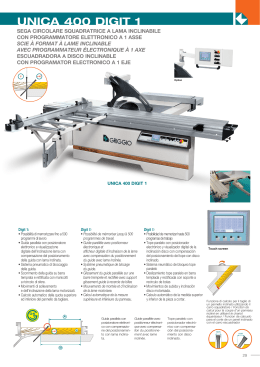
TECHNICAL DATA • TECHNISCHE DATEN
FICHE TECHNIQUE • TECHNISCHE GEGEVENS
DATI TECNICI
8
1
0
2
3
4
5
6m
LOAD DIAGRAM
BELASTUNGSDIAGRAMM
DIAGRAMME DE CHARGE
LASTDIAGRAM
CURVE DI CARICO
7
6
To the left of the curve the indicated loads can be handled with
any loader function provided that the positions of the booms are
optimized from a force point of view.
5
Links von der Kurve kann angegebene Last mit wahlfreier Funktion gehoben werden, vorausgesetzt dass Hub- und Wipparm in
der Position sind in der diese die maximale Hubkraft besitzen.
4
A gauche de la courbe, la charge indiquée peut etre
manutentionnée avec n’importe quelle fonction de grue, à condition
que la position des flèches soit optimisée.
3
2
4000 kg
1
3500 kg
(1)
(1)
De aangegeven belasting kan binnen het werkbereik met elke
funktie van de kraan worden geheven, indien elk van de
giekdelen het max. giekmoment levert.
Alla sinistra della curva di carico la prestazione indicata é
ottenibile con qualsiasi funzione gru, ottimalizzando l’assetto di
forza dei bracci.
4000 kg
0
2760 kg
2220 kg
1
1800 kg
2
1470 kg
3
4
(1)
Inner hook attachment
Innere Hakenbefestigung
Avec attache supplémentaire
Binnenste haakbevestiging
Gancio all´ attacco interno
0
1
2
3
4
5
6
7
8
9 10 11 12 13m
14
13
12
11
10
9
8
7
6
RANGE DIAGRAM
BEWEGUNGSDIAGRAMM
DIAGRAMME DE PORTEE
WERKBEREIK
DIAGRAMMA DI ESCURSIONE
Range diagram for hydraulic telescoping extensions
Hydraulische Reichweite
Diagramme de portée pour rallonges télescopiques
hydrauliques
Hydraulisch bereik, standaard
Diagramma con sfili idraulici
Range diagram with manual extensions
Reichweite mit manuellen Verlängerungen
Diagramme de portée avec rallonges manuelles
Werkbereik met mechanische giekverlengingen
Diagramma con prolunghe
5
4
3
2
1
0
1
2
3
4
5m
308
200
Min. = 3 534
*
Max. = 5 284
160
2011
1931
1200
1946
max. 920
596
700
171
Centre of gravity (without support legs)
666 (2)
Schwerpunktzentrum (ohne Seitenstützen)
45
Centre de gravité (sans stabilisateurs)
Zwaartepunt (zonder steunpoten)
Baricentro (senza stabilizzazione)
192
73
/
188
982
982
1204
CENTRE
OF FRAME
2397
Rotation space needed
400°
Schwenkradius
Alt.1 and 2
734
Espace necescaire pour la rotation
Benodigde draairuimte
Alt. 1
633
Alt. 2
Ingombro in rotazione
Outriggers max extended
C
Ø190
A
P= Stützbeinkraft abhängig von der Last, einschließ
dynamischem Effekt bei max. Stützbeinhub
470
P= Effort aux vérins d'appui dû a la charge et aux effets
dynamiques, à écartement maxi
P= Steunpootkracht t. g. v. de last, incl. dynamische
effecten, bij volledig uitgeschoven steunpoten
B
P
P
510
494
198 222
87
226 220
512
P= Reazione su stabilizzatore dovuta al carico e agli sforzi
dinamici, con barre stabilizzatrici totalmente estratte
518
1547
P= Support leg force due to payload incl. dynamic effect
784
654
50°
1417
308
539
454
/ 194
6
*
Outrigger legs • Stützbeine • Stabilisateurs
Steunpoten • Sistema di stabilizzazione
40 267
523
(2) Hose and pipe kit
(2) Rohr und Schlauchsatz
(2) Kit de tuyauteries
(2)
Slang- en leidingset
(2)
Attivazioni idrauliche
A
B
C
P kN
Weight
kg
Fixed
Feste
Fixed
Vaste
Fisso
2281
Manually extendable
Manuell ausziehbare
Extensibles manuallement
Handuitschuifbaar
Con estensione manuale
2353 3250 1177
2353 4501 1177
2353 5320 1177
64.2
44.4
38.5
136
186
286
Manually extendable and tiltable
Manuell ausziehbare und schwenkbar
Extensibles manuallement et basculant
Handuitschuifbaar en draaibaar
Con estensione manuale e stabilizzatori orientabili
2413 3311 1207
2413 4561 1207
2413 5380 1207
63.0
43.8
38.1
150
200
300
1141 102.5
89
9
0
1
2
3
4
5
6
7
8m
LOAD DIAGRAM
BELASTUNGSDIAGRAMM
DIAGRAMME DE CHARGE
LASTDIAGRAM
CURVE DI CARICO
8
7
To the left of the curve the indicated loads can be handled with
any loader function provided that the positions of the booms are
optimized from a force point of view.
6
5
Links von der Kurve kann angegebene Last mit wahlfreier Funktion gehoben werden, vorausgesetzt dass Hub- und Wipparm in
der Position sind in der diese die maximale Hubkraft besitzen.
4
A gauche de la courbe, la charge indiquée peut etre
manutentionnée avec n’importe quelle fonction de grue, à condition
que la position des flèches soit optimisée.
3
(1)
2
3870 kg
1
3370 kg (1)
3250 kg
0
2500 kg
1
2000 kg
2
1300 kg
De aangegeven belasting kan binnen het werkbereik met elke
funktie van de kraan worden geheven, indien elk van de
giekdelen het max. giekmoment levert.
Alla sinistra della curva di carico la prestazione indicata é
ottenibile con qualsiasi funzione gru, ottimalizzando l’assetto di
forza dei bracci.
1000 kg
3
4
5
(1)
Inner hook attachment
Innere Hakenbefestigung
Avec attache supplémentaire
Binnenste haakbevestiging
Gancio all´ attacco interno
0
1
2
3
4
5
6
7
8
9 10 11 12 13m
14
13
12
11
10
9
8
7
6
RANGE DIAGRAM
BEWEGUNGSDIAGRAMM
DIAGRAMME DE PORTEE
WERKBEREIK
DIAGRAMMA DI ESCURSIONE
Range diagram for hydraulic telescoping extensions
Hydraulische Reichweite
Diagramme de portée pour rallonges télescopiques
hydrauliques
Hydraulisch bereik, standaard
Diagramma con sfili idraulici
Range diagram with manual extensions
Reichweite mit manuellen Verlängerungen
Diagramme de portée avec rallonges manuelles
Werkbereik met mechanische giekverlengingen
Diagramma con prolunghe
5
4
3
2
1
0
1
2
3
4
5m
308
Min. = 3 673
200
Max. = 7 173
max. 1400
155
171
596
700
Centre of gravity (without support legs)
(2)
Schwerpunktzentrum (ohne Seitenstützen)
666
2011
1931
1300
1946
*
Centre de gravité (sans stabilisateurs)
45
Zwaartepunt (zonder steunpoten)
Baricentro (senza stabilizzazione)
192
73
188
/
982
982
1204
CENTRE
OF FRAME
2404
Rotation space needed
400°
Schwenkradius
Alt.1 and 2
734
Espace necescaire pour la rotation
Benodigde draairuimte
Alt. 1
633
Ingombro in rotazione
Alt. 2
Outriggers max extended
C
Ø190
A
P= Stützbeinkraft abhängig von der Last, einschließ
dynamischem Effekt bei max. Stützbeinhub
470
P= Effort aux vérins d'appui dû a la charge et aux effets
dynamiques, à écartement maxi
P= Steunpootkracht t. g. v. de last, incl. dynamische
effecten, bij volledig uitgeschoven steunpoten
B
P
P
510
494
198 222
82
226 220
512
P= Reazione su stabilizzatore dovuta al carico e agli sforzi
dinamici, con barre stabilizzatrici totalmente estratte
518
1547
P= Support leg force due to payload incl. dynamic effect
784
654
50°
1417
308
539
454
/ 194
6
*
Outrigger legs • Stützbeine • Stabilisateurs
Steunpoten • Sistema di stabilizzazione
60 267
523
(2) Hose and pipe kit
(2) Rohr und Schlauchsatz
(2) Kit de tuyauteries
(2)
Slang- en leidingset
(2)
Attivazioni idrauliche
A
B
C
P kN
Weight
kg
Fixed
Feste
Fixed
Vaste
Fisso
2281
Manually extendable
Manuell ausziehbare
Extensibles manuallement
Handuitschuifbaar
Con estensione manuale
2353 3250 1177
2353 4501 1177
2353 5320 1177
64.2
44.4
38.5
136
186
286
Manually extendable and tiltable
Manuell ausziehbare und schwenkbar
Extensibles manuallement et basculant
Handuitschuifbaar en draaibaar
Con estensione manuale e stabilizzatori orientabili
2413 3311 1207
2413 4561 1207
2413 5380 1207
63.0
43.8
38.1
150
200
300
1141 102.5
89
TECHNISCHE DATEN FICHE TECHNIQUE
TECHNISCHE
GEGEVENS
DATI TECNICI
Kapazitätsklasse, max.
Couple de levage, maximum
Hefvermogen, max.
Prestazione
Standardausladung,
hydraulisch
Portée hydraulique,
standard
Hydraulisch bereik,
standaard
Braccio standard
Ausladung hydr.
Teleskopausschieber
Course de rallonge
hydraulique
Hydraulische
gierkverlenging
Corsa sfilo idraulico
Zugkraft hydr.
Teleskopausschieber
Force de traction du
vérin télescope
Uitschuifcilinder
trekkracht
Forza sfilo in rientro
Druckkraft hydr.
Teleskopausschieber
Force de poussée du
vérin télescope
Uitschuifcilinder
drukkracht
Forza sfilo in uscita
Ausladung man.
Armverlängerung
Portée avec rallonge
manuelle
Bereik met mechanische
giekverlenging
Braccio con prolunghe
Hubhöhe über
Kransockel, hydr./man.
Hauteur de levage au-dessus
du plan de pose, hydr./man.
Hefhoogte vanaf montage plaat,
hydr./handmatige bediening
Altezza di sollevamento da base gru
con braccio standard/con prolunghe
Ausladung – Tragkraft,
Standard (3)
Portée – force de levage,
standard (3)
Bereik – hefvermogen
standaard (3)
Sbraccio - portate,
standard (3)
Ausladung – Tragkraft,
man. Armverlängerung (3)
Portée – force de levage,
rallonge manuelle (3)
Bereik – hefvermogen
met mechanische verlenging (3)
Sbraccio - portate,
con prolunghe (3)
Empf. Ölfördermenge
Débit rec.
Aanbeloven pompopbrengst
Mandata olio consigliata
Kraftbedarf bei empf.
Ölfördermenge
Puissance requise au
débit rec.
Benodigd pompvermogen bij
aanbeloven pompopbrengst
Potenza richiesta con mandata
olio consigliata
Arbeitsdruck
Pression de travail
Werkdruk
Pressione
Tankinhalt
Volume d’huile dans le réservoir
Olie in tank
Rifornimento olio
Tankgrösse
Capacité du réservoir
Volume olietank
Capienza serbatoio
Schwenkbereich
Angle de rotation
Zwenkbereik
Rotazione
Max. Schrägstellung
bei max. Hubkraft
Angle possible pour couple
de levage maximum
Max. zwenkhoek bij
maximum hefvermogen
Inclinazione superabile a max
prestazione
Coppia di rotazione
Bruttoschwenkmoment
Couple de giration, brut
Bruto zwenkmoment
Schwenkgeschwindigkeit
Vitesse de rotation
Zwenksnelheid
Velocità di rotazione
Hubgeschwindigkeit bei std.
Ausladung hydr./empf.
Ölfördermenge
Vitesse de levage avec
portée hydraulique standard
et débit rec.
Hefsnelheid bij standaard
hydraulisch bereik en
aanbeloven pompopbrengst
Velocità di sollevamento con
braccio standard e mandata
olio consigliata
Zeit für Teleskopbewegung
Aus/Ein
Temps de manoeuvre du
télescop, sortie/rentrée
Hydraulische uitschuiftijd
uit/in
Velocità sfili idraulici in uscita/in
rientro
Höhe in Transportstellung
Hauteur en position
de transport
Hoogte in transportpositie
Altezza gru ripiegata
Breite in Transportstellung
Largeur en position
de transport
Breedte in transportpositie
Larghezza gru ripiegata
Einbauplatzbedarf
Espace de montage requis
Benodigde inbouwruimte
Base gru
Gewichte:
Poids:
Gewichten:
Pesi:
Kran in Standardausführung ohne Seitenstützen
Grue standard sans
vérin d’appui
Standardkraan
zonder steunpoten
Gru standard senza sistema di
stabilizzazione
Hochsitz
Siège
Hoogzit
Comando alto
Brieden
Fixations
Frame montagedelen
Tiranti di aggraffaggio
Seitenstützen – Ausrüstung
Stabilisateurs
Steunpoten
Sistema di stabilizzazione
Tankinhalt
Huile dans réservoir
Oile in tank
Rifornimento olio
We reserve the right to introduce changes in design
Konstruktionsänderungen vorbehalten
Droit de modification réservé
Konstruktiewijzigingen voorbehouden
Dati forniti con riserva di modifiche per perfezionamenti
Designed and strength calculated in accordance with DIN 15018, crane group B3
Berechnungsgrundlage für Konstruktion und Festigkeit ist die Norm DIN 15018, Belastungsgruppe B3
Concue avec une résistance mécanique conformément aux normes DIN 15018, grue capacité B3
Ontwerp en berekeningen zijn uitgevoerd volgens DIN 15018, kraangroep B3
Progetto a norma tecnica DIN 15018 condizione di impiego B3
TECHNICAL
DATA
Lifting capacity, max.
HIAB 071 A
HIAB 071 AW
74 kNm (7.5 tm)
70.6 kNm (7.2 tm)
Hydraulic outreach,
standard
5.30 m
7.20 m
Hydraulic boom
extension
1.75 m
3.50 m
Extension cylinder
pulling force
44.4 kN
36.5 / 42 kN
Extension cylinder
pushing force
33.9 kN
56 / 30.4 kN
Outreach, manual
extension
12.5 m
12.4 m
7.3 / 14.2 m
9.10 / 14.2 m
Lifting height above
installation level, hydr./man.
Outreach – lifting capacity,
standard (3)
Outreach – lifting capacity,
manual extension (3)
1.8 m – 4000 kg
3.4 m – 2220 kg
5.1 m – 1470 kg
7.0
9.1
10.9
12.3
m
m
m
m
– 1000
– 540
– 400
– 320
(1)
1.8
3.6
5.4
6.9
kg
kg
kg
kg
m
m
m
m
– 3870
– 2000
– 1300
– 1000
kg
kg
kg
kg
(1)
9.0 m – 540 kg
10.8 m – 400 kg
12.2 m – 320 kg
Rec. oil flow
30 l/min
30 l/min
Power needed at rec.
oil flow
14 kW
14 kW
22.5 MPa
22.5 MPa
Working pressure
Oil in tank
45 l
Tank capacity
60 l
60 l
Slewing angle
400 °
400 °
6 °
6°
12.7 kNm
12.7 kNm
Max. slope viable
at full capacity
Slewing torque, gross
Slewing speed
Lifting speed at
standard hydraulic outreach
and rec. oil flow
Hydraulic boom extension
time out/in
45 l
15 °/s
15 °/s
0.7 m/s – 5.3 m
0.9 m/s – 7.2 m
10 / 7 s
20 / 13 s
Height in folded
position
2011 mm
2011 mm
Width in folded
position
2400 mm
2410 mm
Installation space needed
600 mm (670 mm(2))
600 mm (670 mm(2))
880 kg
995 kg
Weights:
Loader in standard version
without support legs
Top-seat
Frame attachments
Support leg equipment
135 kg
(2)
135 kg
30 – 38 kg
30 – 38 kg
89 – 300 kg
89 – 300 kg
36 kg
36 kg
Oil in tank
(1)
Inner hook attachment
Innere Hakenbefestigung
Avec attache supplémentaire
Binnenste haakbevestiging
Gancio all´ attacco interno
(3)
Lifting capacity at + 20-25° inner boom position
Hubkapazität bei + 20-25° Hubraumposition
Capacité de levage avec un angle de flêche de + 20-25°
Hefcapaciteit bij een hefarmhoek van + 20-25°
Prestazione con braccio principale da + 20-25
(2)
Incl. hose and pipe kit
Inkl. Rohr und Schlauchsatz
Avec kit de tuyauteries
Met slang- en leidingset
Con attivazioni idrauliche
(2)
Prrinted in Sweden by TRYCK-MEDIA I HUDIKSVALL AB
Cranes sold on the European market are CE-marked and
thus certify compliance with the Machinery Directive.
The World´s No.1 Selling Articulated Crane
HIAB is a Partek Cargotec Company
1792 EU 01.99
Scaricare