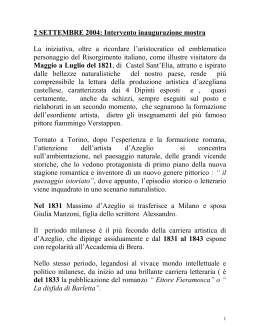
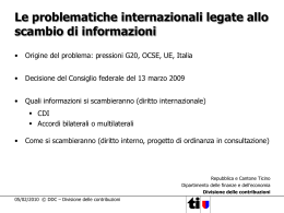
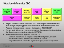
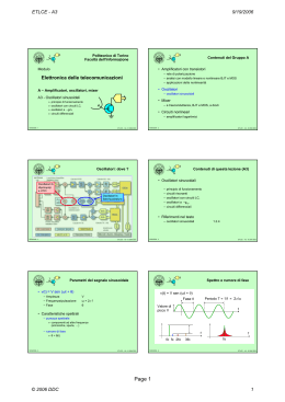
ElapE1 26/11/2012 Ingegneria dell’Informazione Sistemi elettronici ELETTRONICA APPLICATA E MISURE SENSORI Dante DEL CORSO AA 2012-13 CONDIZIONAMENTO IN. CONV A/D ELABORAZIONE CONV D/A CONDIZIONAMENTO OUT Dispositivi di potenza Limiti operativi Analisi termica Circuiti di comando Problemi: - gestire alte correnti (tensioni) - dissipazione/temperatura - ottenere buona efficienza 26/11/2012 - 1 ElapE1 - © 2012 DDC 26/11/2012 - 2 ElapE1 - © 2012 DDC Gruppo E: Gestione dell’energia Lezione E1: circuiti di potenza • Come fornire energia a un sistema elettronico • Parti “di potenza” in un sistema elettronico – Alimentatori – Batterie primarie/secondarie • Dispositivi: modelli e parametri (da Sist e Tecn. ELN) – Diodi raddrizzatori e zener – Transistori: MOS, BJT, altri • Caratteristiche di componenti “di potenza” – Limiti di correnti/tensioni – Problemi termici, SOA • Limiti operativi – Safe Operating Area – Analisi termica • Esempi di circuiti di potenza – – – – Alimentatori e regolatori lineari Regolatori a parzializzazione (commutazione) Stadi di uscita Protezioni 26/11/2012 - 3 • Dispositivi BJT e MOS usati come interruttori • Riferimenti: – M. Zamboni: Elettronica dei sistemi di interc. e acq.: cap. 6 ElapE1 - © 2012 DDC 26/11/2012 - 4 ElapE1 - © 2012 DDC Dove occorre gestire potenza Altri moduli funzionali “di potenza” • Alimentatore (fornisce energia quasi costante) • Conversione dell’energia – Fornire energia ai vari moduli, partendo da – – – – » Tensione di rete (220V, 50/60 Hz) » Batterie, celle solari, … – Tensione di uscita ben definita, al variare di » Energia di ingresso (rete, stato batterie, …) » Energia richiesta in uscita (corrente al carico) » Temperatura e altri parametri ambientali ACDC: “alimentatore” classico DCDC: alimentazioni a batteria, alim. isolate, regolatori, … DCAC: inverter (generare 220V da batterie) ACAC: trasformatori – Chimica ↔ DC: batterie, accumulatori – Meccanica ↔ AC/DC: generatori e motori • Amplificatori/circuiti di potenza (energia variabile) – Altro: Celle solari , … – Visti come “alimentatori variabili” • Per tutti: alto rendimento/basse perdite • Entrambi: alto rendimento/basse perdite 26/11/2012 - 5 ATTUATORI SISTEMA DI ALIMENTAZIONE E1 – CIRCUITI DI POTENZA » » » » CIRCUITI DI POTENZA ElapE1 - © 2012 DDC 26/11/2012 - 6 ElapE1 - © 2012 DDC Page 1 © 2012 DDC 1 ElapE1 26/11/2012 Esempio 1: Conversione AC DC Zener diodes • All junctions have breakdown • Raddrizzatore a una semionda – Vi è AC – Condensatore per avere tensione di uscita costante (DC o quasi) – Vo è DC con ondulazione • Breakdowns usually must be avoided (damage!) • Some devices are designed to operate in breakdown without degradation: ZENER diodes • Used for • Circuito base per la conversione da AC a DC – Protection circuits – Low power voltage regulators – Cheap reference voltage sources 26/11/2012 - 7 ElapE1 - © 2012 DDC 26/11/2012 - 8 Zener diode i(v) characteristic Zener diode equivalent circuit • Iz and Vz have inverse sign from Id, Vd • Vzo: Vz for I = 0 (linear model) – “Standard” diodes operates in forward/reverse bias » Breakdown is a fault condition I Rz • Rz: ΔV/ΔI (actually differential rz) – Zener operates in reverse bias (breakdown) Iz Vzo I Slope ΔV/ΔI = Rz • Pdmax (or Izmax): limited by temperature rise Vz + V • Izmin: minimum current to exit knee region Id Vd ElapE1 - © 2012 DDC Izmin Pdmax V Vzo 26/11/2012 - 9 ElapE1 - © 2012 DDC 26/11/2012 - 10 ElapE1 - © 2012 DDC Zener diode applications Zener diode operating point • The reverse breakdown voltage can be used to get a stable voltage reference • Select I, V sign as for diodes • Draw characterisitc of left-side bipole (Vs + R) – Breakdown voltage Vz – Output voltage of circuit shown is equal to Vz, despite variations in input voltage V • Draw Dz I(V) characteristic • Operating point (Va, Ia) at intersection • The resistor R limits the current in the diode • Detailed analysis: I V Vsu Dz I Va, Ia Vsu/Rs V • Evaluate effect of Vsu and Rs – Consider quiescent current 26/11/2012 - 11 Rs + – If Dz operates in breakdown Vo regulation ElapE1 - © 2012 DDC 26/11/2012 - 12 Vsu ElapE1 - © 2012 DDC Page 2 © 2012 DDC 2 ElapE1 26/11/2012 Power BJT devices Switch or amplifier? • Fundamental relation for BJT: • Use as amplifier – Ic = β Ib – Vce, Ic ≠ 0 – Active region • Most relevant parameters for power applications: – – – – Vcebr Icmax β Vcesat C-E breakdown voltage max collector current current gain (low for high currents) C-E voltage drop in saturation • Use as switch ON – Vce ≈ 0 – Saturation Ic Ib – Thermal parameters • Use as switch OFF » Max power, Thermal resistance V be • Use specific technology (vertical) – Ic ≈ 0 – Cutoff V ce – More current in the same area (higher density) 26/11/2012 - 13 ElapE1 - © 2012 DDC 26/11/2012 - 14 ElapE1 - © 2012 DDC BJT as a switch Critical saturation parameters • Operating points are on the load line • Operation is based on minority carriers – Slow dynamic behavior, Temperature dependence • High Vcesat (depends on Ic; about 0.1 1 V) • β decreases for high currents – Low current gain (5 … 20), evel lower for high voltage devices RB • Critical behavior near saturation – High Ic, residual Vce High power dissipation • Design solution – Guarantee deep saturation (high Ib drive, or Darlington conf.) 26/11/2012 - 15 ElapE1 - © 2012 DDC 26/11/2012 - 16 ElapE1 - © 2012 DDC Cutoff model for BJT • Ib = 0 Ic = 0 Power MOS-FET (ideal) • Planar structure – Low power devices – Current and breakdown voltage ratings function of the channel W & L. • BC junction leakage current: Icbo – If base open, enters as Ib, causing Iceo = β Icbo • Iceo causes power dissipation – Temperature rise higher leakage current further temperature rise … Thermal runaway • Vertical structure – Voltage rating function of doping and thickness of N-epitaxial layer (vertical) – Current rating is a function of the channel W & L – A vertical structure can sustain both high V & I • Multiple devices, with current partition (avoid hot spot) • Steer Icbo away from Base – R to GND – Reverse bias BE (but no breakdown!) 26/11/2012 - 17 ElapE1 - © 2012 DDC 26/11/2012 - 18 ElapE1 - © 2012 DDC Page 3 © 2012 DDC 3 ElapE1 26/11/2012 Power MOS-FET parasitics MOS-FET output characteristic • The vertical structure creates a pn junction from body (S) to substrate (D) • Current can always flow from S to D S G • The power MOS is a 1-quadrant switch • Warning! D – Saturation in MOS has a different meaning (called “active” region in BJT) – 4-quadrant requires at least two MOS – The vertical structure creates also a parasitic BJT (not indicated) 26/11/2012 - 19 ElapE1 - © 2012 DDC 26/11/2012 - 20 ElapE1 - © 2012 DDC MOS-FET switching models MOS-FET vs BJT • ON: • MOS-FET use majority carriers – Equivalent resistance Ron – High switching speed – Reduced temperature dependence • OFF: • MOSFET can use simpler driving circuit – Leakage current Ioff – No DC Gate current, only charge Gate-body capacitor – Fast switching requires circuits able to drive a high-C load • Dynamic • ON state – GS capacitance – DS capacitance – Parasitic towards substrate – BJT modeled as Vcesat (+Ron) – MOS modeled as Ron • OFF state: both modeled as current source (leakage) 26/11/2012 - 21 ElapE1 - © 2012 DDC 26/11/2012 - 22 ElapE1 - © 2012 DDC Four-layer devices SCR in CMOS logic circuits • Some devices are designed for switching applications: • SCR structure intrinsic in CMOS ICs – Responsible for latch up – Specific physical structure (4-layer or more) – Can be used only as switches (not for linear amplifiers) • Triggered by – Input levels out of GND-Vcc range – High energy particles (space applications!) • Examples: – Silicon Controlled Rectifier (SCR), Tyristor – TRIAC/DIAC pMOSFET VDD • A parasitic SCR is “intrinsic” on CMOS inputs n+ – When ON, high current may damage the circuit – Requires proper circuit design 26/11/2012 - 23 S G p+ nMOSFET D D p+ n+ G S n+ T1 p-well VSS p+ T2 n-substrate ElapE1 - © 2012 DDC 26/11/2012 - 24 ElapE1 - © 2012 DDC Page 4 © 2012 DDC 4 ElapE1 26/11/2012 Lesson E1: power devices Operating limits • Dispositivi: modelli e parametri (richiami) • Breakdown voltage – If higher, insulating layers are broken • Limiti operativi • Max current • Dispositivi BJT e MOS di potenza – If higher, wires or conducting paths can melt • Operating limits • Max power – Safe Operating Area – Power dissipation – Thermal model – Power dissipation causes temperature rise (see max temp.) • Max temperature – Silicon/metal can melt, doping & parameters modified, … • Using BJT switches • Special application parameters • Using MOS-FET switches – Radiation in space, vibration, …. 26/11/2012 - 25 ElapE1 - © 2012 DDC 26/11/2012 - 26 ElapE1 - © 2012 DDC Safe Operating Area Safe Operating Area (BJT) • Any electronic devices can handle limited power, voltage, current Too high current • The region of acceptable V,I is the Safe Operating Area (SOA), defined by Too high V x I (power) - not uniform current flow - high local power dissipation – Power limit (V x I > Pdmax) » Excess power cause temperature rise, with melting » Secondary breakdown: local heating and thermal runaway – Voltage (V < Vbrk) Too high voltage Active & Safe Operating Area (SOA) » Excess voltage causes breakdown and insulator perforation – Current (I < Imax) » Excess current cause heating and metal evaporation 26/11/2012 - 27 ElapE1 - © 2012 DDC 26/11/2012 - 28 ElapE1 - © 2012 DDC Power dissipation Power derating • Manufacturers specify • All electric devices dissipate a power Pd = V I – Power dissipation causes temperature increase – Any device has temperature limits power limits – Max power dissipation Pdmax – Max junction operating temperature Tjmax • Power dissip. modeled with thermal equivalent circuits • Power dissipation causes temperature rise – Power current – Temperature node voltage – Heat conduction capability thermal resistance θr (°/W) • Allowed power dissipation decreases with Ta • Diodes/MOS/BJT power dissipated on the junctions – Ta = Tjmax Pd = 0 – Heat must be brought outside, through a path including » Junction-case – defined by manufacturer » Case-ambient – controlled by designer using heat sinks 26/11/2012 - 29 ElapE1 - © 2012 DDC 26/11/2012 - 30 ElapE1 - © 2012 DDC Page 5 © 2012 DDC 5 ElapE1 26/11/2012 Thermal model From junction to ambient • The thermal path from junctin to ambient consists of: • “Electric network” model for thermal behaviour – Power Pd – Temperature T – Heat conduction θ current source node voltage thermal resistance θr (°/W) – Junction-Case: θJC » Thermal resistance defined by the package – Case-heatSink: θCS • Electrical equivalent circuit » Case and fixture – Heatsink-ambient: θSA • Tj – Ta = Pd θja » Heatsink and operating condition (air flow) • Each device has Tjmax – Tj = Ta + Pd θja • Designer can control θCS and θSA 26/11/2012 - 31 ElapE1 - © 2012 DDC 26/11/2012 - 32 ElapE1 - © 2012 DDC Example: Thermal specification Lesson E1: Power devices • From datasheet TIP30 • Dispositivi: modelli e parametri (richiami) • Limiti operativi • Dispositivi BJT e MOS di potenza • Operating limits • Using BJT and MOS switches – ON/OFF state parameters – Command circuits • Example: junction temperature for Pd = 0,8 W? – ΔTj = Pd RθJA = 62,5 x 0,8 = 50°C – Tj = Ta + ΔTj = 75°C 26/11/2012 - 33 ElapE1 - © 2012 DDC 26/11/2012 - 34 ElapE1 - © 2012 DDC Switch interfaces Power dissipation • Goal: drive Power Switches from logic circuits • Full ON or full OFF power close to 0 – Logic circuit electrical parameters • Intermediate state (active area) – Load parameters » » » » Type: R, L, C, I, V Required V and I Transition time (overvoltage/current, EMC) Special requirements (Galvanic insulation, …) – – – – Occurs during transients V and I ≠ 0 Power dissipation Pd = V x I Max Pd for Vce = Vsu/2 – Power device parameters » » » » V, I, P max; SOA Configuration; High/Low side, floating Active device parameters (current gain, Vt, …) Dynamic behavior 26/11/2012 - 35 • Reduce duration of transients – Fast switching – Tradeoff with parasitics losses ElapE1 - © 2012 DDC 26/11/2012 - 36 ElapE1 - © 2012 DDC Page 6 © 2012 DDC 6 ElapE1 26/11/2012 BJT low-side drive circuit MOS-FET switches VS • With NPN BJT – Emitter to GND, load L on Collector – Command to Base (close to GND) • OFF: RL L IB – Vgs < Vt Id=0 (cutoff) IC • ON • ON – Icon = Vs/Rl – Provide enough base current (Ib > Icon/β) – Vgs > Vt Id=Vds/Rd (triode region) • OFF • Rd depends on – Bring base current to 0: sub-threshold or reverse bias – Avoid BE reverse breakdown (typ 5 V) – Avoid thermal runaway for Icbo multiplication 26/11/2012 - 37 – Vgs, Vds, Temperature, ….. ElapE1 - © 2012 DDC 26/11/2012 - 38 ElapE1 - © 2012 DDC MOS low-side drive circuit MOS switch drive from logic circuit • Load to Vs, switch to GND • Vt < Vh Direct drive • With n-MOS device • Power devices have high Gate capacitance – – – – Source to GND, load on Drain Command to Gate (close to GND) ON: Vgs > Vt OFF: Vgs < Vt – Fast transition to limit power dissipation – High current drive (dynamic) for the Gate – Special driving circuits • Parasitic inductance of Gate wire combined with the capacitor makes a LC with high Q, • With p-MOS device, control referred to Vs – Can cause high overvoltage on Gate – Damping resistor close to gate – May require non-standard logic levels – Add n-MOS level translator 26/11/2012 - 39 ElapE1 - © 2012 DDC 26/11/2012 - 40 ElapE1 - © 2012 DDC Floating MOS switch drive Floating load – H bridge • Both D and S of the switch at undefined voltage • Floating load, with complementary drive on each side: H bridge – Sample/hold circuit – “floating” loads • Voltage and current reverse in the load • Use voltage drop on a floating resistor • 2x voltage, 4x power • Two commands – Active/OFF – Direction • Zero power consumption when load OFF • Used also for amplifiers: steady state has no DC 26/11/2012 - 41 ElapE1 - © 2012 DDC 26/11/2012 - 42 ElapE1 - © 2012 DDC Page 7 © 2012 DDC 7 ElapE1 26/11/2012 Overvoltage protection Lesson E1: final test • Describe the I(V) behavior of Zener diodes • Inductive loads create a significant overvoltage at turn OFF, due to current flowing in the inductance. • How can we guarantee that a BJT switch goes fully in ON state? – Provide a path for current when the switch is OFF – Limit the voltage on Collector/Drain • List relevant parameters for MOS transistors used as switches. • Catch diode • Which are the boundaries of SOA for MOS power devices? – low impedance path to dissipate the energy stored in the inductor • Draw the circuit to drive a floating switch from a logic signal. • Plot output V(I) characteristic of a MOS or BJT power device, and identify the various operating regions. » SW closed: diode reverse-biased, no current flow » SW opens: the current in L continue to flow through the diode • Which parameters defines the boundary of SOA? • How can we evaluate the actual temperature of a power semiconductor junction? – With MOS, internal diode can dissipate a limited energy 26/11/2012 - 43 ElapE1 - © 2012 DDC 26/11/2012 - 44 ElapE1 - © 2012 DDC Page 8 © 2012 DDC 8
Scaricare