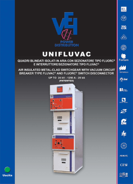
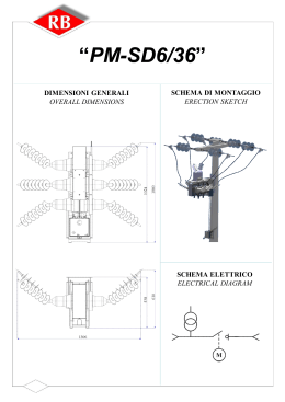
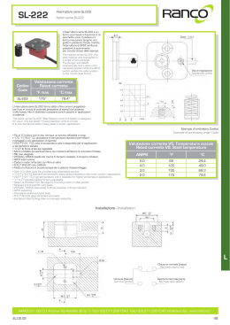
VACUUM CIRCUIT-BREAKER
SEL S.p.A.
Via Amendola - 51035 LAMPORECCHIO (PT) - ITALY
Website: www.sel-electric.com e-mail: [email protected]
Indice
Index
Indice
Descrizione generale
Generalità
Norme
Prove di tipo
Prove individuali
Tecnologia del vuoto
Peculiarità interruttore TCB
Principi di interruzione
Arco diffuso o contratto in vuoto
La geometria a spirale dei contatti
delle ampolle in vuoto ABB
Caratteristiche funzionali
Comando meccanico
Versioni disponibili
Fattore di correzione di altitudine
p. 3
Index
p. 4
General description
p. 4
p. 4
p. 4
p. 4
p. 5
p. 5
p. 6
p. 6
p. 6
General information
Standards
Type tests
Routine tests
Vacuum technology
Unique characteristics of TCB CB
Principles of interruption
Diffuse or contracted vacuum arcs
The spiral geometry of ABB vacuum
interrupter contacts
p. 3
p. 4
p. 4
p. 4
p. 4
p. 4
p. 5
p. 5
p. 6
p. 6
p. 6
p. 7
Functional characteristics
p. 7
p. 7
p. 7
p. 8
Operating mechanism
Versions available
Altitude correction factor
p. 7
p. 7
p. 8
Caratteristiche elettriche
p. 9
Electrical characteristics
p. 9
Accessori
p. 10
Accessories
p. 10
Accessori a richiesta
(o ricambi)
p. 11
Accessories on request
(or spare parts)
p. 11
Dati dimensionali
p. 12
Overall dimensions
p. 12
Schemi elettrici
p. 13
Electrical diagrams
p. 13
TCB
ed. 0601
3
Descrizione generale
General description
Generalità
I nostri interruttori in vuoto della serie TCB sono sistemi a
pressione sigillata e garantita (Norme IEC 62271-100 e
CEI 17/1) realizzati a poli separati ciascuno dei quali
contiene una ampolla sotto vuoto che, grazie ad un
particolare processo produttivo, viene inglobata in resina.
Ciò garantisce la protezione dell’elemento principale
dell’interruttore da urti, fenomeni di condensazione,
accumulo di polvere ed assicura la tenuta all’impulso
atmosferico sulla superficie esterna dell’ampolla.
La trasmissione del movimento è ottenuta per mezzo di un
albero centrale e consente di trasformare ’interruttore da
comando laterale destro in sinistro in maniera
estremamente semplice.
General information
Our medium voltage vacuum circuit breakers for indoor
installation TCB series are “sealed for life” pressure
systems (IEC 62271-100 and CEI 71-1 Standards) and
they are constructed using the separate pole technique.
Each pole has a vacuum interrupter inside it which, thanks
to a special production process, is incorporated in the
resin. This construction technique ensures protection of
the vacuum interrupter against impact, dust and
condensation phenomena and guarantees the lightning
impulse withstand also on the external surface of the
vacuum interrupter.
The transmission is obtained by a mechanical central bar
which allows to transform the circuit breaker in different
executions very easily.
Targa caratteristiche
10
1
9
2
3
8
4
7
6
5
Norme
Standards
Prove di Tipo
Type tests
CEI EN 62271-100
IEC 62271-10
CEI EN 60694
IEC 62271-1
−
−
−
−
Tenuta all’isolamento a frequenza industriale
Tenuta all’isolamento con impulso atmosferico
Prove di tenuta alla corrente breve durata
Potere di stabilimento e d’interruzione alla corrente di
c.to c.to
Prove individuali
−
−
−
−
Prove funzionali elettriche e meccaniche
Tenuta all’isolamento a frequenza industriale
Misura della resistenza dei circuiti principali
Prova d’isolamento circuiti ausiliari e del comando
4
1 Nameplate
Segnalazione stato interruttore
2 Mechanical signalling for CB open/closed
Blocchi meccanici a chiave
3 Keylock
Leva di comando
4 Opening/closing knob
Comando carica molle
5 Shaft for manual spring charging
Segnalazione molle cariche
6 Springs charged signalling
Telaio di supporto
7 Chassis
Poli
8 Poles
Trasmissione movimento
9 Transmission
Contatti principali
10 Main contacts
CEI EN 62271-100
IEC 62271-10
CEI EN 60694
IEC 62271-1
−
−
−
−
Dielectric test at rated frequency
Dielectric test with atmospheric impulse
Short-time withstand current test
Making capacity and breaking capacity tests
Routine tests
−
−
−
−
Electrical and mechanical functional tests
Dielectric test at rated frequency
Measurement of the resistance of the main circuit
Dielectric test on auxiliary and control circuit
TCB
ed. 0601
Descrizione generale
General description
Tecnologia del vuoto
E’ ormai evidente che l’interruttore in vuoto per media
tensione rappresenti già la tecnologia dominante sul
mercato e che la sua diffusione stia crescendo in
maniera forte. Infatti oggi è possibile ottenere interruttori
in vuoto efficienti, con durata elettrica che supera quella
meccanica, innocui dal punto di vista ambientale (il gas
SF6 degli interruttori, oltre a contribuire all’effetto serra,
necessita di un rischioso trattamento di scarto sia per la
manutenzione che una volto giunti a fine vite
dell’apparecchio); ma soprattutto con prestazioni
superiori per ridotta energia d’arco, ripristino
dell’isolamento dopo una
sovratensione, tempi di 80%
apertura minimi, ridotta
70%
energia meccanica per il
60%
comando.
50%
40%
30%
20%
10%
0%
1990
Peculiarità del progetto TCB è quella di sfruttare l’ausilio
della particolare forma del collegamento elettrico
all’interno del polo per aumentare la forza di pressata
del contatto mobile durante la chiusura in caso di
elevate correnti di guasto. La connessione tra il
terminale dell’ampolla ed il contatto dell’interruttore
forma una spira la quale genera un campo
magnetico proporzionale alla corrente che la
percorre; la forza di questo campo magnetico si
dispone in maniera tale da sommarsi alla forza
meccanica impressa dal comando. Maggiore è la
corrente di guasto tanto più elevata è la forza della
spira che contribuisce al buon funzionamento
dell’interruttore.
TCB
ed. 0601
It is a known fact that the vacuum circuit breaker has
become the dominant technology in the main world
market and its diffusion is increasing in an outstanding
way. Today it is possible to get very efficient vacuum
circuit-breakers with electrical duration which is longer
than mechanical duration, with total respect of
environment (SF6 circuit breakers contribute to
greenhouse effect and they need maintenance and a
particular treatment at the end of their life cycle); but in
particular, vacuum circuit-breakers offer the best
performances thanks to the reduction of arc energy, very
quick opening, insulation
VACUUM restoring after overvoltage
impulse and reduction of
SF6
mechanical energy needed
for operating mechanism.
OIL
AIR
1980
Peculiarità interruttore TCB
Vacuum technology
2000
2010
Unique characteristics
breaker
of
TCB
circuit
In case of short circuit TCB exploits a particular form of
the electric connection inside its poles to increase
pressure force of the movable contact during the closing
operation. The connection between the terminal of the
vacuum interrupter and the contact of the circuit-breaker
forms a coil which produces a magnetic field
proportional to the passing current. The strength of
this magnetic field is added to mechanic force of the
operating mechanism. Greater is the fault current
more elevated is the strength of the coil that
contributes to the good performances of the circuit
breaker.
5
Principi di interruzione
Principles of interruption
Arco diffuso o contratto in vuoto
In seguito alla separazione dei contatti, si ha la
formazione di singoli punti di fusione sulla superficie del
catodo. Ciò provoca la formazione di vapori metallici
che supportano l’arco stesso. L’arco diffuso è
caratterizzato dall’espansione sulla superficie del
contatto stesso e da stress termico uniformemente
distribuito. Al valore nominale di corrente dell’ampolla,
l’arco elettrico è sempre di tipo diffuso. L’erosione del
contatto è molto contenuta ed il numero di interruzioni è
molto elevato. Con l’aumento del valore di corrente
interrotta (oltre il valore nominale) l’arco elettrico tende
a trasformarsi da diffuso in contratto per effetto Hall.
Partendo dall’anodo l’arco si contrae e man mano che
la corrente aumenta tende a concentrarsi. Soffietti
In corrispondenza dell’area interessata si Bellows
ha un incremento di temperatura con il
conseguente stress termico del
Parte mobile
contatto. Per evitare
Movable contact
il surriscaldamento e
l’erosione dei contatti, si
mantiene in rotazione l’arco;
con la rotazione l’arco diviene
assimilabile ad un conduttore mobile
attraverso il quale passa la corrente.
Diffuse or contracted vacuum arcs
Following contact separation, single melting points form
on the surface of the cathode, producing metal vapours
which support the arc. The diffuse vacuum arc is
characterised by expansion over the contact surface and
by an even distribution of the thermal stress. At the rated
current of the vacuum interrupter, the electric arc is
always of the diffuse type. Contact erosion is negligible,
and the number of current interruptions very high. As the
interrupted current value increases (above the rated
value), the electric arc tends to be transformed from the
diffuse into the contracted type, due to the Hall effect.
Starting at the anode, the arc contracts and as the
current rises further it tends to become sharply defined.
Near the area involved there is an increase in
Contatti elettrici
Electric contacts
temperature with consequent thermal stress
on the contact. To prevent
overheating and erosion of the
contacts, the arc is kept
rotating. With arc rotation it
becomes similar to a
moving conductor which
the current passes
Parte fissa
through.
Fixed contact
Scudo di condensazione di vapore di metallo
Metal vapor condensation shield
La geometria a spirale dei contatti delle
ampolle in vuoto
La particolare geometria dei contatti a spirale genera un
campo magnetico radiale in ogni zona della colonna
d’arco concentrata sulle circonferenze dei contatti. Si
autogenera una forza elettromagnetica che agisce
tangenzialmente provocando la rotazione veloce
dell’arco attorno all’asse dei contatti. In questo modo
l’arco viene forzato a ruotare e ad interessare una
superficie più ampia rispetto a quella di un arco
contratto fisso. Tutto ciò, oltre a limitare lo stress
termico dei contatti, rende trascurabile
l’erosione dei contatti e, soprattutto,
permette di controllare il processo di
interruzione anche con correnti di corto
circuito molto elevate. Le ampolle in vuoto
sono a corrente zero e sono esenti da
riadescamenti. La rapida riduzione della
densità di corrente e la rapida
condensazione dei vapori metallici
contemporaneamente all’istante zero di
corrente consentono di ristabilire la
massima tenuta dielettrica tra i contatti
dell’ampolla entro pochi millesimi di
secondo.
6
Involucro di isolamento
Insulating envelope
The spiral geometry of vacuum interrupter
contacts
The special geometry of the spiral contacts generates a
radial magnetic field in all areas of the arc column,
concentrated over the contact circumferences. An
electromagnetic force is self-generated and this acts
tangentially, causing rapid arc rotation around the
contact axis. This means the arc is forced to rotate and
to involve a wider surface than that of a fixed contracted
arc. Apart from minimising thermal stress on the
contacts, all this makes contact erosion negligible and,
above all, allows the interruption process
even with very high short-circuits. Vacuum
interrupters are zero-current devices and
are free of any re-striking. Rapid reduction
in the current charge and rapid
condensation of the metal vapours
simultaneously with the zero current allow
to restore maximum dielectric strength
between the interrupter contacts within
microseconds.
TCB
ed. 0601
Caratteristiche funzionali
Functional characteristics
Comando meccanico
Operating Mechanism
Versioni disponibili
Versions available
Il comando meccanico ad accumulo di energia, a sgancio
libero, con chiusura ed apertura indipendenti dall’azione
dell’operatore consente di eseguire un ciclo O-C-O senza
bisogno di ricaricare le molle; inoltre garantisce la
sequenza a ciclo rapido (O-0,3s-CO-3min-CO)
permettendo l’utilizzo come richiusore automatico.
Per il controllo a distanza dell’interruttore è prevista una
serie completa di accessori elettrici quali motore carica
molle, bobina di chiusura, sganciatore di apertura a lancio
di corrente o per minima tensione oltre ai contatti ausiliari
di stato.
L’interruttore è disponibile in tre versioni:
- TCB:esecuzione standard per quadri MT protetti tipo
ICBV o ILCBV
- TCB/LD:esecuzione su carrello per quadri protetti
comando laterale destro; realizzato in due varianti una a
12kV ed una a 24kV
- TCB/LS: esecuzione su carrello per quadri protetti
comando laterale sinistro; realizzato in due varianti una
a 12kV ed una a 24kV
TCB
ed. 0601
The stored energy type operating mechanism with free
release and with opening and closing operations
independent of the operator allows to carry out a complete
cycle O-C-O without necessity to spring charging; besides
it is suitable for the rapid (0-0,3s-CO–3min-CO) reclosing
cycle. Remote control of the circuit-breaker is possible by
means of applying special electrical accessories (spring
charging motor, shunt opening release, etc.).
The circuit-breakers are available in three versions:
- TCB: standard for metal enclosed MV modules ICBV or
ILCBV
- TCB/LD: on truck version with right lateral operating
mechanism. There are two version of this, 12kV and
24kV.
TCB/LS: on truck version with left lateral operating
mechanism. There are two version of this, 12kV and
24kV.
7
Caratteristiche funzionali
Functional characteristics
Fattore di correzione dell’altitudine
Per installazioni al di sopra dei 1000m occorre tenere
presente di un coefficiente correttivo ricavabile dal grafico
a fianco costruito sulle indicazioni specifiche di norma.
In pratica si devono moltiplicare per il coefficiente Ka i
valori delle tensioni di prova a frequenza industriale, ad
impulso atmosferico e ad impulso di manovra tra fase e
fase (curva m=1); il valore della tensione di prova a
impulso di manovra longitudinale (m=0,9); il valore di
tensione di prova a impulso di manovra fase-terra
(m=0,75).
Per cui ad esempio:
Altitudine d’installazione: 2500 m
Tensione d’isolamento: 12 kV
Tensione di prova a frequenza industriale: 28 kVrms
Tensione di prova impulse atmosferico: 75 kVp
Ka fattore di correzione =1.20.
Cosniderando quanto sopra I valori di prova (ad altitudine
inferiore a 1000m s.l.m.):
–Tenuta alla frequenza industriale: 28 x 1,20 = 33,6 kVrms
– Tensione impulse atmosferico:75 x 1,20 = 90 kVp.
Altitude correction factor
For the apparatus to be installed over 1000 m above sea
level we must consider an altitude correction coefficient
which can be taken from the graph below, built up on the
basis of the indications in the applicable Standards.
In practice we have to multiply the value of voltage of
power frequency test, or lightning impulse test and phase
to phase switching impulse test (curve m=1); the value of
voltage for longitudinal switching impulse test (curve
m=0,9); the value of voltage for phase to earth switching
impulse test (curve m=0,75).
The following example is a clear interpretation of the
indications given above.
Installation altitude: 2500 m
Rated service voltage of 12 kV
Industrial frequency withstand voltage: 28 kVrms
Impulse withstand voltage: 75 kVp
Ka factor, which can be taken from the graph =1.20.
Considering the above parameters, the apparatus must
withstand (on test at zero altitude, i.e. at sea level):
–power frequency withstand voltage: 28 x 1,20 = 33,6
kVrms
– impulse withstand voltage:75 x 1,20 = 90 kVp.
ALTITUDE CORRECTION FACTOR / Fattore di
Correzione dell'altitudine
1,5
1,45
1,4
1,35
Ka
1,3
1,25
1,2
1,15
1,1
1,05
10
00
13
00
16
00
19
00
22
00
25
00
28
00
31
00
34
00
37
00
40
00
1
Al t i t ude / Al t i t udine
m=1
8
m=0,9
m=0,75
TCB
ed. 0601
Caratteristiche elettriche
Electrical characteristics
Tensione nominale
Rated voltage
Ur
12 kV
24 kV
Tensione nominale di tenuta ad impulso atmosferico
Impulse withstand voltage
Up
75 kV
125 kV
Tensione a frequenza industriale (50 Hz 1 min.)
Dielectric withstand voltage to earth and between phases (50Hz 1min.)
Ud
28 kV
50 kV
Frequenza nominale
Rated frequency
fr
50 Hz
Corrente nominale
Rated current
Ir
630 A **
Potere di interruzione nominale
Rated breaking capacity
Isc
16 - 20 kA
Potere di stabilimento
Making capacity
Ip
40 - 50 kA
Corrente di breve durata
Short-time withstand current
Ik
16 - 20kA
Durata di c.to c.to
Short-circuit time
Tk
3 sec.
Sequenza operazioni
Operation sequence
0 - 0.3 - CO - 3 min. - CO
Durata di apertura
Opening time
45 msec.
Durata d’arco
Arcing time
7 ÷ 15 msec.
Tempo totale d’interruzione
Total breaking time
52 ÷ 60 msec.
Classificazione
Classification
E1 - C1 - M1 *
*: per soluzioni diverse contattare SEL
for different solutions contact SEL
**: per portate maggiori contattare SEL
for better ranges contact SEL
Per tener conto dell’evoluzione delle normative e dei materiali, le caratteristiche elettriche e le dimensioni di ingombro del presente
catalogo si potranno ritenere impegnative solo dopo conferma di SEL.
Possible changes in standards or materials can influence on electrical characteristics and overall dimensions shown in this catalogue.
For this reason they may be considered final only after confirmation by SEL.
TCB
ed. 0601
9
Accessori
Accessories
Standard accessories
Dotazioni standard
−
−
−
−
−
−
−
−
−
−
−
−
−
−
−
−
−
−
Comando manuale
Segnalazione meccanica stato interruttore
Segnalazione meccanica molle cariche
Manipolatore comando
Manovra carica-molle
Blocco a chiave (chiave libera in aperto)
Sganciatore di apertura (Standard 230Vca)
Contatti ausiliari
Cablaggio base e morsettiera aux
Manual operating mechanism
Mechanical signalling for CB open/closed
Springs charged signalling
Opening/closing knob
Spring charging handle
Keylock (Circuit-breaker in open position)
Shunt opening release
Auxiliary contacts
Standard wiring and auxiliary terminal strip
Caratteristiche accessori elettrici
Characteristics of electrical accessories
AUSILIARI
ELETTRICI
ELECTRICAL
AUXILIARY
Bobina di
chiusura
Shunt
Motore
closing
U.M. Spring Charging
motor
M.U.
release
Ps
Tempo di
carica
Charging time
10
Bobina di
apertura
Shunt
opening
release
Pc
Sganciatore di
minima
Contatti
tensione
ausiliari
Undervoltage Auxiliary
release
contacts
Ps
Pc
s
15
Alimentazione
Power Supply
a.c.
V
24-48-110-220 ± 10% (50Hz) ; 120-240 ± 10% (60Hz)
-
d.c.
V
24-48-110 ± 10%
24
Potenza
Power
a.c.
VA
900
190
770
770
d.c.
W
750
150
170
170
a.c. 250V
(cosø1)
A
Corrente
a.c. 250V
nominale
(cosø
0,6)
Rated current
A
d.c. 125V
A
-
100
15
15
6
0,6
TCB
ed. 0601
Accessori a richiesta (o ricambi)
Accessories on request (or spare parts)
TCB
ed. 0601
Sganciatore di apertura
Shunt opening release
Sganciatore di chiusura
Shunt closing release
Contatti ausiliari
Auxiliary contacts
Sganciatore di minima
tensione
Undervoltage release
Blocco a chiave
(interruttore aperto)
Keylock
(circuit-breaker in open
position)
Blocco a chiave doppio
Double Keylock
Motore carica molle
Spring charging motor
Manovra carica molle
Spring charging handle
11
Dati dimensionali
Overall dimensions
ICBV, ILCBV
12
ICB, ICBR, 2ICB
TCB
ed. 0601
Schemi elettrici
Electrical diagrams
-QF.1÷8
-M01
-MC
-MU
Contatti ausiliari
Sganciatore di apertura
Sganciatore di chiusura
Sganciatore di minima
tensione
-MS
Motore carica molle
-FCMU1 Finecorsa inserzione
sganciatore di minima tensione
-MU.2
Contatto sganciatore di minima
tensione
-KXAB Relè anti-pompaggio
-SA
Blocco a chiave interruttore
aperto
-SC.1÷2 Molle cariche
-VB011 Ponte raddrizzatore
-QF.1÷8
-M01
-MC
-MU
-MS
-FCMU1
Auxiliary contacts
Shunt opening release
Shunt closing release
Undervoltage release
Spring charging motor
Position switch of undervoltage
release
-MU.2
Contact of undervoltage
release
-KXAB Anti-pumping relay
-SA
Circuit-breaker keylock in open
position
-SC.1÷2 Springs charged
-VB011 Rectifier
TCB
ed. 0601
13
NOTE
14
NOTES
TCB
ed. 0601
SEL S.p.A.
Via Amendola - 51035 LAMPORECCHIO (PT) - ITALY
Telefono +39-0573/80051
Telefax: +39-0573/803110
Website: www.sel-electric.com e-mail: [email protected]
Scaricare