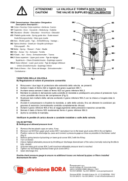
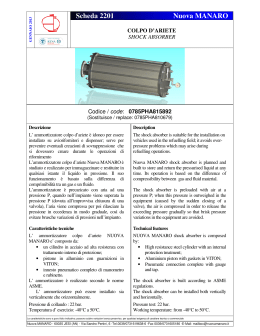
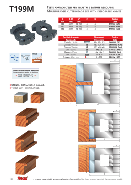
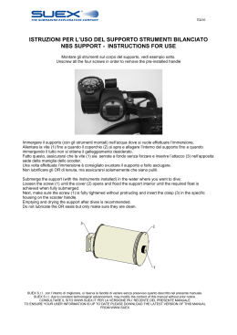
CILINDRO SENZA STELO Ø16
RODLESS CYLINDER Ø16
MONTAGGIO DECELERATORE
MOUNTING THE SHOCK ABSORBER
I
GB
2
1Avvitare i 4 grani nei relativi fori filettati sulle due dita del supporto del deceleratore. ATTENZIONE: i grani non devono
sporgere verso l’interno, questo per poter permettere la fase successiva.
1Tighten the four grub screws in the relevant threaded holes of the two fingers of the shock absorber support.
IMPORTANT: the grub screws must not project inwards; this is to allow
execution of the following operations.
2Inserire il supporto del deceleratore sulla camicia, in prossimità di una delle due testate.
2Fit the shock absorber support onto the barrel, near one of the two end caps.
3Mantenendo saldamente il supporto contro la testata, avvitare i 4 grani in modo alterno ed incrociato. Il tiraggio dei 4 grani deve avvenire con gradualità insieme, non deve essere cioè avvitato completamente un grano prima degli altri.
3Holding the support against the cylinder end caps, tighten the four grub screws alternately. The four grub screws must be tightened gradually, which means that one should never be tightened fully before the others.
4Avvitare il grano di fermo nella posizione desiderata. Non eccedere il valore Bmax indicato nella tabella della figura C.
4Screw the stop grub screw in the desired position. Do not exceed the Bmax value shown in the table in fig. C.
5Una volta individuata la posizione,
bloccare il grano con il dado relativo.
5When the position is correct, lock the stop grub screw with the nut.
6Avvitare il deceleratore facendo
corrispondere quasi la fine della corsa dello stesso alla battuta del grano di fermo.
6Start the shock absorber, taking care to align almast the end of stroke of it with the stop grub screw striker.
7Bloccare il deceleratore con il dado relativo.
7Lock the shock absorber using the nut.
8Svitare la vite “A” sul carrello del cilindro dalla parte del supporto appena montato; sistemare la squadretta “B” a ridosso del carrello stesso, e bloccare la stessa
utilizzando la vite opportuna presente nella confezione del kit.
8Unscrew the screw “A” on the cylinder carriage on the side of the support that has just been mounted.
Fit the bracket “B” against the carriage and lock it using the screw included in the kit.
B
A
DIMENSIONI VERSIONE CON FINECORSA REGOLABILI E
DECELERATORI
DIMENSIONS VERSION WITH ADJUSTABLE LIMIT SWITCH AND
SHOCK ABSORBERS
Fig. C
Ø
16
B Max
42
C1
22
D
W7
M12x1 38
Ø
16
Lavoro max ammort.
Per corsa [J] Per ora [J]
10
14125
W8
46
Forza max
d’urto [N]
1000
WS4
42
Y1
7.5
Forza max
di spinta [N]
220
Z4
7
Z5
7.5
Corsa
10.4
Ø
16
B Max
42
C1
22
D
W7
M12x1 38
Ø
16
Max. cushioned force
For stroke [J] For hour [J]
10
14125
W8
46
WS4
42
Y1
7.5
Z4
7
Z5
7.5
Stroke
10.4
Max. impact Max. thrust
force [N]
force [N]
1000
220
3
GRAFICI PER SCELTA DECELERATORI
ADJUSTABLE LIMIT SWITCH AND DECELERATOR KIT
Le aree tratteggiate indicano la selezione del
deceleratore che viene fornito come standard.
È comunque possibile richiedere selezioni diverse in
funzione della velocità [m/sec], e del lavoro
massimo da dissipare per ogni corsa [J/corsa].
Per determinare la giusta selezione fare riferimento
ai grafici sopra riportati.
The areas filled in with lines refer to the shock
absorber supplied as standard.
Other versions can be requested with different
speeds [m/sec.] and maximum energy dissipated at
each stroke [J/stroke].
Refer to the diagrams above to make the correct
selection.
J/corsa - J/stroke
ISTRUZIONI PER LA REGOLAZIONE DELLA CORSA E DEL DECELERATORE
4
INSTRUCTIONS TO ADJUST THE STROKE AND SHOCK ABSORBER
1Avvitare il grano di fermo nella posizione desiderata.
Non eccedere il valore di Bmax indicato nella tabella della figura C. Una volta individuata la
posizione, bloccare il grano con il dado
relativo. Avvitare il deceleratore facendo
corrispondere quasi la fine della corsa dello stesso alla battuta del grano di fermo (circa 0.5 mm meno).
ATTENZIONE: È IMPORTANTE RISPETTARE
QUESTA ULTIMA CONDIZIONE PER GARANTIRE UN CORRETTO FUNZIONAMENTO DEL
DECELERATORE, ED EVITARE UNA SUA
ROTTURA PREMATURA.
1Screw the stop grub screw in the desidered position.
Do not exceed the Bmax value shown in the table in fig. C. When the position is correct, lock the stop grub screw with the nut. Start the shok absorber, taking care to align almost the end of stroke of it with the stop grub screw striker (about 0.5 mm less)
BE CAREFUL: IT IS IMPORTANT TO FOLLOW THIS LAST CONDITION IN ORDER TO
GUARANTEE THE CORRECT SHOCK ABSORBER OPERATION, AND AVOID ITS PREMATURE FAILURE.
2Bloccare il deceleratore con il dado relativo.
2Lock the shock absorber using the nut.
www.metalwork.eu
ZSSACF002 ITA_GB - IM03 - 10/2014
Scaricare