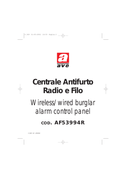
IF15M
SENSORE INFRAROSSO A TENDA A
CURTAIN LENS INTRUSION PIR DETECTOR
INSTALLAZIONE
INSTALLATION
ITALIANO
1. INTRODUZIONE
Il sensore IF15/M è un sensore a raggi infrarossi passivi in grado di creare una barriera di protezione “a tenda” utile per porte e finestre o ovunque sia necessario rilevare un movimento che avviene
lungo un’unica direzione.
2. INSTALLAZIONE E REGOLAZIONE
-Orientare il sensore su corpi fissi che non distino oltre 2,5 metri.
-Agire leggermente sull’inclinazione del sensore per dirigere il fascio solo dove è necessario.
Il sensore IF15/M non deve essere utilizzato :
-In luoghi esposti ad agenti atmosferici (pioggia, vento, grandi sbalzi termici, ecc.).
-In presenza di numerosi insetti.
-A diretta esposizione dei raggi solari.
-In posizione orizzontale o obliqua se orientato verso l’alto.
3. FUNZIONAMENTO E COLLEGAMENTI (FIG 1)
1 – Alimentazione (morsetti 6 – 7). rispettivamente positivo e negativo
2 - Contatto di allarme (morsetti 3 – 4 ) è di tipo N.C (normalmente chiuso).
Perché il contatto di allarme sia funzionante è necessario che il morsetto B/S sia scollegato.
3 - Antistrappo e antiapertura (morsetti 8 – 9). Il contatto TAMPER è di tipo N.C.
4 - Blocco del sensore (morsetto 5) B/S a +12V impianto disinserito. B/S negativo impianto inserito.
Fornendo una tensione positiva sul morsetto B/S è possibile bloccare le segnalazioni di allarme del
contatto ALARM (morsetti 3 e 4) che rimarrà quindi sempre chiuso. Contemporaneamente anche
il led esterno di segnalazione rimarrà sempre spento. Perché il sensore possa segnalare normalmente gli allarmi, lasciare il morsetto B/S scollegato oppure collegarlo al negativo di alimentazione.
5 - Contatto di allarme supplementare (morsetti 1 e 2)
Si tratta di un contatto di allarme di tipo N.O. (normalmente aperto) che può essere utilizzato per
una segnalazione alternativa a quella disponibile sui morsetti 3 e 4 (per esempio, la funzione
campanello). Per attivare il funzionamento di questo contatto di allarme è necessario fornire una
tensione positiva sul morsetto B/S.
6 - Led di segnalazione
L’accensione fissa del led esterno indica lo stato di “allarme” del sensore. Il lampeggio veloce indica una memoria di allarme. Togliere il jumper LED per disabilitare permanentemente l’accensione
del led. Il led non si accende quando sul morsetto B/S è presente una tensione positiva.
7 - Memoria di allarme
La memoria di allarme può essere attivata inserendo il jumper MEMORY e viene segnalata dal
lampeggio del led esterno. Le fasi di memorizzazione e di reset della memoria sono gestite dall’ingresso B/S che può essere collegato direttamente allo stato della centrale:
La memorizzazione di un allarme avviene solo quando B/S è scollegato o collegato a negativo. La
memoria di allarme continua ad essere visualizzata mentre B/S è collegato ad una tensione positiva e viene cancellata nell’instante in cui il morsetto B/S viene nuovamente scollegato (inserimento
impianto).
www.amcelettronica.com
IF15M - v 1.0
installation instructions
8 - Buzzer interno di allarme
Con il buzzer interno al sensore IF15/M è possibile ottenere una segnalazione di allarme sonora.
Per attivare questa funzione inserire il jumper BUZZER. La segnalazione è attivata quando sul
morsetto B/S è presente una tensione positiva e permane per tutto il tempo dell’allarme.
9 – Regolazione sensibilità (trimmer SENS)
“+”
->
maggiore sensibilità
“-“
->
minore sensibilità
Per evitare falsi allarmi si consiglia di iniziare la regolazione dalla posizione MINIMA (-) e di aumentare la sensibilità non oltre quanto effettivamente necessario.
ENGLISH
1. INTRODUCTION AND ADJUSTMENT
IF15/M is a dual-element PIR sensor able to create a curtain barrier for doors, windows or anywhere it is necessary to detect a one way movement.
2. INSTALLATION
- Fix the sensor on a solid surfaces and not farer than 2,5 meters from the ground.
- Act smoothly on the sensor angle in order to orient the lens focus towards the desired zone.
IF15/M cannot be used:
- In places exposed to rain, wind, large thermal range and so on.
- In presence of many bugs.
- If exposed directly to sun radiation.
- Horizontally position or oblique if up oriented.
3. CONNECTION AND SETTINGS (FIG 1)
1 - Power supply (terminals 6 – 7). Supply voltage at terminals +12V and -.
2 - Alarm contact (terminals 3 – 4). Alarm contact is NC (normally closed).
It is essential to leave the terminal B/S unconnected to make the sensor working properly.
3 - Anti-tearing and anti-opening (terminals 8 – 9). Tamper contact is NC (normally closed).
4 - Sensor block (terminal 5). Applying a positive voltage to the terminal B/S it is possible to mask
the alarm signaling of the ALARM contact (terminals 3 and 4) that will be always closed. At the
same time even the LED signaling will be always off. To avoid this block it is possible to connect
this terminal to negative or to leave it float.
5 - Additional alarm contact (terminals 1 and 2). It is a N.O. (normally open) contact that can be
used as additional contact when the sensor is blocked (for instance CHIME). To enable this function it is necessary to give positive to B/S terminal.
6 - LED
If the LED is switched ON there is an ALARM. The fast blinking of the LED is the ALARM MEMORY.
Take off the jumper LED to permanently disable the LED. The LED does not switch on if there is a
positive voltage at terminal B/S.
7 - ALARM MEMORY
Alarm memory can be enabled inserting the jumper MEMORY and it is shown by the LED flashing.
The storing and reset phases of the memory are managed by the input B/S that can be linked directly to the control panel status.
The storing of an alarm happens only when B/S is disconnected or connected to the negative.
The Alarm Memory is still shown while B/S is connected to positive and it is erased when the terminal B/S is disconnected again (System arming).
8 - BUILT IN ALARM BUZZER
With the built-in buzzer it is possible to have a sound signaling. To enable this function it is necessary to insert the jumper BUZZER. The signaling is enabled when there is a positive signal at the
B/S terminal and it is continuous for all the alarm phase.
www.amcelettronica.com
IF15M - v 1.0
installation instructions
9 - SENSITIVITY ADJUSTMENT (SENS trimmer)
It is possible to regulate the sensor sensitivity by adjusting the SENS trimmer of the sensor:
“+” -> more sensitivity
“-“ -> less sensitivity
In order to avoid future false alarms, it is advised to start the adjustment from the MINIMAL position
(-) and to increase the sensitivity not more than effectively necessary.
4. SCHEDA / BOARD (FIG 1)
LED
1
2
N.O.
CHIME
3
4
N.C.
ALARM
B
5
S
-
6
7
+
SUPPLY
BUZZER
MEMORY
8
9
N.C.
TAMPER
FRONT VIEW
SIDE VIEW
90°
A
120cm
B
B =1,5 x A
20cm
www.amcelettronica.com
IF15M - v 1.0
installation instructions
SPECIFICHE TECNICHE / SPECIFICATIONS / SPECIFICATIONS TECHNIQUES
IF15M
Alimentazione / Input Voltage
Consumo / Current Drain (Alarm/Stand-By)
Grado di Protezione IP / IP Grade
Portata in lunghezza / Coverage
Portata in larghezza / Angle
Piroelettrico / PIR
Lente (fasci e livelli) / Lens (beams and levels)
Durata allarme / Alarm period
Antiapertura / Anti-opening
Antistrisciamento / Creep Zone
Contatto di allarme / Alarm’s Contact
Contatto di tamper / Tamper Switch
Temperatura di esercizio / Operating Temperature
Temperatura di stoccaggio / Storage Temperature
RFI Protezione / Protection
Led WALK TEST (MW and PIR)
Cover / Housing
Accessori / Accessories
9 to 15 Vdc
(12 mA / 25mA) @ 13.8 Vdc
IP42
2.5 m
90°
2 elementi / 2 elements
5 patterns on 1 levels
4 sec.
✔
✔
100 mA - 40 V - 16 Ω
Max 40 mA - 30 Vdc
From -25 °C to +55 °C
From -20 °C to +60 °C
10 V / m (20 /1000 MHz)
✔
ABS
Dimensioni / Dimensions
110 x 60 x 46 mm
Meets the requirements/Conforme ai requisiti:
EN50131-2-2:2008
EN50131-2-2 : Grade 2
EN50131-2-2 : Environmental Class III
L’installazione deve essere eseguita a regola d’arte da personale specializzato.
Il costruttore declina ogni responsabilità nel caso in cui il prodotto venga manomesso da persone non autorizzate.
Si raccomanda di verificare il corretto funzionamento del sistema d’allarme almeno una volta al mese, tuttavia un sistema
di allarme elettronico affidabile non evita intrusioni, rapine, incendi o altro, ma si limita a diminuire il rischio che tali situazioni si verifichino.
Installation must be carried out following the local installation norms by qualified personnel.
The manufacturer refuses any responsibility when changes or unauthorized repairs are made to the product/system.
It is recommended to test the operation of the alarm product/system at least once a month. Despite frequent testing and
due to, but not limited to, any or all of the following: tampering, electrical or communication disruption or improper use, it
is possible for the product/system to fail to prevent burglary, rubbery, fire or otherwise. A properly installed and maintained
alarm system can only reduce the risk that this happens.
www.amcelettronica.com
IF15M - v 1.0
installation instructions
Scaricare