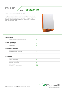
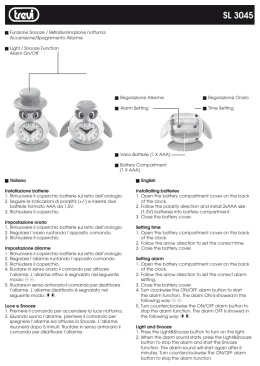
C.369 31-05-2002 16:55 Pagina 2
Centrale Antifurto
Radio e Filo
Wireless/wired burglar
alarm control panel
COD.
C.369 - 03 - 250500
AF53994R
C.369 31-05-2002 16:55 Pagina 3
I
Centrale Antifurto
Radio e Filo
COD.
AF53994R
I
C.369 31-05-2002 16:55 Pagina 2
INDICE
Introduzione. . . . . . . . . . . . . . . . . . . . . . . . . . . . . . . . . . . . . . . . . . . . . . . . . . . . pag. 3
Caratteristiche tecniche . . . . . . . . . . . . . . . . . . . . . . . . . . . . . . . . . . . . . . . . . . . . pag. 3
- Condizioni climatiche
- Riferimenti normativi
Alimentatore . . . . . . . . . . . . . . . . . . . . . . . . . . . . . . . . . . . . . . . . . . . . . . . . . . . pag. 4
Descrizione funzionamento. . . . . . . . . . . . . . . . . . . . . . . . . . . . . . . . . . . . . . . . . . pag. 5
- Inserimento/disinserzione/parzializzazione
- Funzionamento normale
- Condizione di test
- Condizione di allarme intrusione
- Condizione di allarme manomissione
- Condizione di allarme 24h
- Condizione di allarme scanner
Descrizione frontale e segnalazioni . . . . . . . . . . . . . . . . . . . . . . . . . . . . . . . . . . . . pag. 8
Periferiche del sistema . . . . . . . . . . . . . . . . . . . . . . . . . . . . . . . . . . . . . . . . . . . . . pag. 9
- Telecomando per inserzione disinserzione e parzializzazione dell’impianto
- Telecomando per attivazione degli allarmi rapina e panico
- Rivelatore IR-P
- Rivelatore perimitrale multifunzione
- Indicatore remoto di stato impianto
- Sirena via radio autoalimentata per esterni
Collegamento alimentazione di rete e batteria . . . . . . . . . . . . . . . . . . . . . . . . . . . pag. 19
Morsettiera collegamento e schema applicativo. . . . . . . . . . . . . . . . . . . . . . . . . . . pag. 19
AVVERTENZE
I prodotti devono essere commercializzati in confezione originale, in caso contrario al rivenditore e/o installatore è fatto obbligo di applicare e di trasmettere all'utilizzatore le istruzioni d'uso che accompagnano il prodotto. Dopo aver aperto l'imballaggio, assicurarsi dell'integrità dell'apparecchio, nel dubbio non utilizzare
l'apparecchio e rivolgersi a personale professionalmente qualificato. L'apparecchio, anche se imballato, deve
essere maneggiato con cura e immagazzinato in luogo asciutto ad una temperatura compresa tra
–5…+40°C.
Si ricorda inoltre:
• Togliere tensione agendo sull'interruttore generale prima di operare sull'impianto.
• Curare in modo particolare la preparazione dei terminali dei cavi da inserire nei morsetti dell'apparecchio
per evitare la riduzione delle distanze di isolamento tra gli stessi.
• Serrare le viti dei morsetti con cura per evitare surriscaldamenti che potrebbero provocare un incendio o il
danneggiamento dei cavi.
• Il prodotto, se non diversamente specificato, è destinato all'utilizzo in luoghi asciutti e non polverosi.
Per ambienti particolari utilizzare prodotti specifici.
I
-2-
C.369 31-05-2002 16:55 Pagina 3
INTRODUZIONE
AF53994R è una centrale antifurto a 3 zone - 4 canali, che permette la connessione di rivelatori
sia radio che con fili. Dispone inoltre di 3 canali di tipo 24h dedicati a: allarme panico, allarme
rapina, allarme tecnico. Una ulteriore linea tamper a filo è utilizzabile per proteggere tutti gli elementi esterni. La centrale alloggia internamente alimentatore e batterie ricaricabili (le batterie non
sono in dotazione), ed è dotata di un telecomando per l’inserzione totale o parzializzata dell’impianto e la disinserzione. Incorpora un buzzer piezoelettrico di elevata potenza per la segnalazione di conferma alle manovre dell’utente. È realizzata in contenitore in materiale plastico con dimensioni 12 moduli DIN, adatto sia per l’installazione in quadro elettrico che a parete.
CARATTERISTICHE TECNICHE
• 4 canali /3 zone sono così suddivise:
- Zona A: formata da canale 1 e canale 2 entrambe collegabili sia via filo che via radio ai
relativi rivelatori. Canale 1 con tempo di ingresso di 30 sec.
- Zona B: formata da canale 3 con collegamento radio ai rivelatori
- Zona C: formata da canale 4 con collegamento radio ai rivelatori
• Canale di tipo 24h per allarme panico via radio
• Canale di tipo 24h per allarme rapina via radio
• Canale di tipo 24h per allarme tecnico via radio
• Tamper Radio/Filo
• Telecomando per l’inserzione totale o parzializzata dell’impianto e la disinserzione.
• Telecomando per attivazione degli allarmi “Rapina” e “Panico”.
• Possibilità di collegare via radio N° 64 periferiche (rivelatori, telecomandi).
• Chiave meccanica incorporata
• Buzzer interno a due livelli di intensità sonora per segnalazione allarmi e conferma manovre.
• Ingresso nominale da rete c.a.: Vn = 230Vca –15% + 10%
• Assorbimento max alla tensione nominale: 80 mA
• Alimentatore interno con due uscite:
- 13,8V per ricarica batteria interna
- 14,5 V per batteria sirena autoalimentata esterna
• Batteria: 12V/1,2Ah costituita da 2 elementi 6V al Pb–acido ermetici
• Massima corrente erogabile dall’alimentatore: 280 mA
• Classificazione della parte radio:
- Frequenza della portante: 433.92 MHz
- Potenza massima del trasmettitore: 10mW
- LPD di classe 1 secondo I-ETS 300 220 e CEPT T/R 01-04
• Portata nominale del collegamento: 30 metri in condizioni normali nell’ambiente abitativo
(pareti metalliche o strutture antisismiche possono ridurre la portata). Evitare l’installazione di
AF53994R e dei rivelatori radio a meno di 2cm da pareti metalliche.
Condizioni climatiche
I requisiti e le prestazioni della centrale secondo norma CEI 79-2 vengono garantiti secondo le
-3-
I
C.369 31-05-2002 16:55 Pagina 4
seguenti condizioni climatiche:
• Temperatura e umidità relativa di riferimento: 25°C - U.R. 65%
• Campo temperatura ambiente di funzionamento: da –10°C a +50°C
• Umidità relativa massima: 90% a +35°C
• Altitudine: 2000m s.l.m.
Riferimenti normativi
• Parte avente collegamenti a Filo: conforme al 1° livello di prestazioni secondo la CEI79.2 ove
applicabile.
• Parte avente collegamenti via Radio: omologazione del Ministero delle Poste e delle
Telecomunicazioni.
La centrale AF53994R è inoltre conforme alle norme generiche di emissione (EN50081-1) ed
immunità (EN50082-1) certificata da Competent Body (parte avente collegamenti via radio).
ALIMENTATORE
L’alimentatore interno alla centrale prevede due uscite:
• Uscita per alimentazione impianto via filo e ricarica batteria interna, 13,8 Vcc (morsetto 1).
• Uscita per ricarica batteria sirena autolimentata, 14,5 Vcc (morsetto 7)
L’uscita dell’alimentatore è protetta elettronicamente contro i sovraccarichi; la corrente totale, sulle
due uscite non deve superare il valore massimo di 280 mA.
Sono inoltre previste due protezioni elettroniche contro i sovraccarichi e i corto circuiti:
• PTC1 (0,7A): protezione uscita alimentazione impianto e comando sirena
• PTC 2 (0,7A): protezione contro inversioni di polarità della batteria
Per agevolare il calcolo dell’assorbimento totale, per la parte dell’impianto via filo, è fornita la
tabella:
Assorbimento
Totale
Codice
Descrizione
Q.tà
(mA)
assorbimento (mA)
AF53994R
Centrale
13 mA
1
13 +
AF45…57
Riv. D.T. incasso
10 mA
.........
......+
AF45…58
Riv. IR-P incasso
6,5 mA
.........
......+
AF959
Riv. IR-P parete
12 mA
.........
......+
AF958
Riv. IR-P parete
7 mA
.........
......+
AF960
Riv. IR-P parete
0,1 µA
.........
......+
AF45...60
Riv. IR-P incasso
0,1 µA
.........
......+
.........................
.........
.........
......+
.........
.........
.........................
Valore max.: 50mA
Nota: per garantire un’autonomia, in assenza rete, all’impianto pari a 24h è opportuno non
superare il valore di assorbimento massimo pari a 50 mA.
-4I
C.369 31-05-2002 16:55 Pagina 5
DESCRIZIONE DEL FUNZIONAMENTO
Inserimento-disinserimento-parzializzazione
Le operazioni di inserimento, disinserimento e parzializzazione dell’impianto possono essere effettuate come di seguito descritte, tramite il telecomando, solo quando la chiave meccanica è in
posizione ON.
La chiave in posizione PROG. porta il sistema in condizione di programmazione e TEST.
INSERIMENTO
TOTALE
Premere il pulsante ROSSO del telecomando: si ha l’accensione di tutti
i led di Zona (A-B-C) e l’emissione di 3 beep di conferma; i LED si
spengono allo scadere del tempo di uscita, fisso a 60 secondi.
Al termine del tempo di uscita si accende il LED INSERITO/ON
DISINSERIMENTO
Premere il pulsante VERDE del telecomando, prima di entrare nell’area
protetta: si ha un lungo beep di conferma ; i led dei canali che hanno
memorizzato allarmi lampeggiano (alcuni dispositivi d’allarme ripetono
le segnalazioni ottico-acustiche tipiche delle manovre ON/OFF).
INSERIMENTO
PARZIALE
È possibile inserire le Zone A - B - C singolarmente come segue.
1. premere contemporaneamente i pulsanti ROSSO e VERDE del telecomando: lampeggiano in sequenza i LED di zona A (canali 1e 2),
zona B e zona C.
2. per escludere la zona desiderata, premere il pulsante VERDE oppure
quello ROSSO durante il lampeggio del LED relativo. Al termine della
sequenza si ha l’emissione dei 3 beep. I LED relativi alle zone inserite rimarranno accesi fino al termine del tempo d’uscita.
Funzionamento normale
Il funzionamento è abilitato solo con chiave meccanica in posizione ON. La commutazione della
chiave in PROG. disabilita gli allarmi e le manovre di inserzione/disinserzione dell’impianto rendendo possibili gli interventi per programmazione, manutenzione e test.
Con centrale disinserita i led eventualmente lampeggianti indicano “allarme memorizzato”. Tale
lampeggio continua per 30” dopo la manovra di disinserzione e può essere ripristinato ad ogni
nuova pressione del pulsante VERDE del telecomando.
La memorizzazione degli allarmi viene annullata alla successiva inserzione dell’impianto premendo il pulsante ROSSO del telecomando. L’inserimento dell’impianto disabilita per 60 secondi
(tempo di uscita) la ricezione di tutti i segnali provenienti dai rivelatori antintrusione di zona.
Condizione di TEST
Ponendo la chiave meccanica in posizione “Programmazione” la centrale è automaticamente in
condizione di TEST. Quando riceve un segnale di allarme (via radio o filo) emette un “Beep” di
conferma. Manomettendo un rivelatore si accendono contemporaneamente il LED del canale inte-5I
C.369 31-05-2002 16:55 Pagina 6
ressato e il LED di manomissione con l’emissione di un beep.
Condizione di allarme intrusione
Con centrale inserita, Il segnale di allarme intrusione proveniente dai rivelatori radio e/o filo provoca la seguente sequenza d'allarme:
• commutazione del relè di allarme e relativa attivazione della sirena autoalimentata (morsetto N.
8) e della sirena ausiliaria (morsetto N. 5), collegate via filo alla centrale.
• Attivazione della sirena AF53901R collegata via radio alla centrale.
• Attivazione del buzzer interno alla centrale. Lo stesso genera una segnalazione acustica ad
alta intensità
• Attivazione dell'uscita per il comando del Buzzer esterno (morsetto14)
• Attivazione dell'uscita dedicata al combinatore telefonico (morsetto 10)
La sequenza d'allarme dura 2 minuti e si ripete in caso di nuova segnalazione proveniente dai
rivelatori.
Ogni canale si autoesclude dopo essere stato interessato a 3 allarmi consecutivi.
La zona interessata all'allarme provoca una memorizzazione che verrà resa visibile solo all'atto
della disinserzione dell'impianto.
La commutazione in "disinserito" provoca anche l'interruzione immediata dell'allarme in corso.
La sequenza d'allarme così descritta vale per i 4 canali, tenendo conto che:
• Il canale A1 è ritardato di 30 sec. (tempo di ingresso). In caso di allarme, durante il tempo di
ingresso, la centrale emette una serie di "Beep".
• Qualora il canale A1 riceva per primo un’allarme, il ritardo d’ingresso di 30 sec. si estende
anche ai canali A2, B, C. I canali A2, B, C si intendono “a percorso d’ingresso”.
NOTA: nel caso in cui non siano collegati dei rivelatori via filo sugli ingressi A1 e A2 è necessario collegare in morsettiera un ponticello che ne simuli la presenza:
• Zona A1: ponticello tra i morsetti 16 e 18
• Zona A2: ponticello tra i morsetti 17 e 18.
Condizione di allarme per Manomissione (Tamper).
Il segnale di allarme manomissione può provenire via radio dai relativi rivelatori (ogni rivelatore
via radio trasmette, in caso di manomissione del proprio involucro, il segnale di manomissione),
oppure via filo (linea tamper collegata ai morsetti 18 e 19).
In caso di manomissione della centrale e/o dei rivelatori, la sequenza d’allarme è ugale a quella
dell’allarme intrusione se la centrale si trova nello stato di “inserito”; se la centrale si trova nello
stato di “disinserito” la sequenza d’allarme differisce nel fatto che non viene attivata la sirena
AF53901R, collegata via radio alla centrale.
Nel caso in cui l’allarme tamper provenga da un riv. radio, lo stesso è visualizzato in centrale dal
LED tamper e dal LED del canale interessato. Nel caso in cui l’allarme provenga dalla linea filo o
dal microswitch a protezione della centrale, è visualizzato in centrale solo dal LED tamper.
Se la linea Tamper (via filo) non è collegata è necessario collegare in morsettiera, tra i morsetti 18 e 19, un ponticello che ne simuli la presenza.
I
-6-
C.369 31-05-2002 16:55 Pagina 7
NOTA: prima di procedere al cambio delle pile dei rivelatori radio sarà opportuno predisporre
la chiave meccanica in PROGRAMMAZIONE, per evitare segnalazioni ottico acustiche di manomissione.
Condizione di allarme 24h
Programmando opportunamente rivelatori perimetrali multifunzione e/o telecomandi si possono
avere i seguenti allarmi indipendenti dallo stato di "inserito" o "disinserito" della centrale. (vedi
tabella seguente)
PANICO
(ALARM 1)
Attiva:
• il buzzer interno (segnalazione acustica ad alta intensità) per 15 s
• il buzzer esterno (morsetto 14), per 15 s
• le sirene collegate via filo (morsetti 5 e 8)
• la sirena AF53901R collegata via radio alla centrale ad impianto
attivo.
• uscita per combinatore telefonico (morsetto 10)
RAPINA
(ALARM 2)
Attiva per 15 secondi un’uscita a collettore aperto, dedicata, per il
comando di un combinatore telefonico (morsetto 11).
ALLARME
TECNICO
(ALARM 3)
Attiva per 15 secondi un’uscita a collettore aperto, dedicata, per il
comando di un combinatore telefonico (morsetto 12). Attiva inoltre il
Buzzer interno (segnalazione acustica a bassa intensità) per 15 s e il
Buzzer esterno (morsetto 14).
Condizione di allarme scanner
La centrale è provvista di un particolare circuito in grado di rilevare un tentativo di manomissione
effettuato tramite uno scanner. Il circuito segnala un allarme quando intercetta un tentativo di ricostruzione del codice normalmente inviato da telecomando, oppure quando è trasmessa una portante fissa, a 433 MHZ, volta a saturare e quindi disabilitare la parte di ricezione radio.
La condizione di allarme scanner è segnalata come nella tabella di seguito riportata.
Nota: gli allarmi manomissione e 24h sono interrotti e/o disabilitati ponendo in PROGRAMMAZIONE la chiave meccanica oppure premendo il tasto VERDE del telecomando AF939R - (in questo caso non esiste autoesclusione, dopo 3 allarmi).
AD IMPIANTO
INSERITO
Attiva:
• l’uscita dedicata per 15 s (morsetto 13)
• il buzzer interno alla centrale (segnalazione acustica ad alta intensità, escludibile tramite JP1 - previsto sulla scheda della centrale - vedi
Fig. 1)
• il buzzer esterno (morsetto 14)
AD IMPIANTO
DISINSERITO
Attiva l’uscita dedicata per 15 s (morsetto 13)
-7-
I
C.369 31-05-2002 16:55 Pagina 8
DESCRIZIONE FRONTALE E SEGNALAZIONI (Fig. 1)
JP1
Tasto Reset
ZONE A1
ALARM
1
ZONE A2
ALARM
2
ZONE
B
ALARM
3
ZONE
C
TAMPER
Buzzer interno
Chiave
RETE / POWER
INSERITO / ON
TX ON
ON
AF53994R
UNITA' CENTRALE / CENTRAL UNIT
PROG.
230 V~ 50 Hz / 80 mA
LED
TIPO DI
Funzione Colore COLLEGAMENTO
Rete
I
Verde
ACCESO
SPENTO
Rete presente
Rete assente
LAMPEGGIANTE
(ad imp. disinserito)
Inserito
Verde
Inserito
Non inserito
Tx on
Giallo
Trasmissione in corso
Trasmissione non in corso
Zona A1
Rosso
Radio o Filo
Zona A1 in Allarme
Zona esclusa o non in Allar. Allarme memorizzato
Zona A2
Rosso
Radio o Filo
Zona A2 in Allarme
Zona esclusa o non in Allar. Allarme memorizzato
Zona B
Rosso
Radio
Zona B in Allarme
Zona esclusa o non in Allar. Allarme memorizzato
Zona C
Rosso
Radio
Zona C in Allarme
Zona esclusa o non in Allar. Allarme memorizzato
Alarm 1
Rosso
Radio
Allarme panico (Linea 24h)
non in allarme
Allarme memorizzato
Alarm 2
Rosso
Radio
Allarme rapina (Linea 24h)
non in allarme
Allarme memorizzato
Alarm 3
Rosso
Radio
Allarme tecnico (Linea 24h)
non in allarme
Allarme memorizzato
Tamper
Rosso
Radio o Filo
Allar. manomiss. (Linea 24h)
non in allarme
Allarme memorizzato
-8-
C.369 31-05-2002 16:55 Pagina 9
Nota segnalazione di batteria bassa: Lo stato di batteria che richiede intervento e/o sostituzione
è segnalato nel modo seguente.
• Ad impianto inserito e all’atto del disinserimento: emissione di 30 “Beep” veloci e lampeggio
simultaneo dei LED per 30 sec. (la segnalazione è ripetuta ogni volta che viene inviato un
comando di disattivazione tramite telecomando).
• All’atto dell’inserimento: emissione di 30 “Beep” veloci con lampeggio simultaneo dei LED per
30 sec. ed emissione di 1 allarme al termine del tempo di uscita.
• Ad impianto inserito: emissione di 1 allarme (la condizione è memorizzata, alla successiva
disattivazione, tramite LED TAMPER).
Nota segnalazione di porta aperta / non pronto all’inserimento: Nel caso in cui un rivelatore
perimetrale (opportunamente programmato tramite il microswitch 3 per trasmettere la segnalazione
di porta rimasta aperta - vedi pag. 15) rilevi la condizione di porta aperta, all’atto dell’attivazione
dell’impianto in centrale si avrà la seguente segnalazione:
- lampegio, durante il tempo di uscita, del LED relativo al canale interessato unitamente ad un
“beep” di circa 10 sec. Al termine del tempo d’uscita NON si avrà l’emissione di una segnalazione d’allarme. La centrale si comporterà in questo modo durante il tempo di uscita anche nel
caso in cui all’atto dell’inserimento la condizione di allarme provenga da un ingresso via filo.
PERIFERICHE DEL SISTEMA
AF939R TELECOMANDO per inserimento disinserimento e parzializzazione del sistema (Fig2)
Pulsante rosso
Pulsante verde
LED
Caratteristiche tecniche
• Alimentazione: pila alcalina 12V - standard 23M, VR22
• Assorbimento: 20 mA in trasmissione
• Autonomia: dipende dal numero di manovre - 6 mesi minimo
• Funzioni operative:
- inserimento impianto
- disinserimento impianto
- parzializzazione impianto
• Caratteristiche R.F.: trasmissione A.F. quarzata a 433,92 MHZ potenza max 10mW
• Codifica segnali: codice random 36 BIT, preimpostato.
- Oltre 68 miliardi di combinazioni.
• Portata utile: più di 40 m in aria libera. Circa 30 m in ambienti residenziali.
• Dimensioni: 78 x 24,5.
-9-
I
C.369 31-05-2002 16:55 Pagina 10
Programmazione
Questo telecomando permette, come descritto nel paragrafo descrizione del funzionamento, di
inserire, disinserire e parzializzare l'impianto. Dispone di due pulsanti, uno verde e uno rosso.
Per memorizzare il codice del telecomando nella memoria della centrale, procedere come segue:
1 porre la chiave meccanica in PROGRAMMAZIONE
2 aprire il contenitore della centrale, saranno emessi 3 "beep" di conferma ed acceso il LED “
ZONE A1”, condizione di inizio programmazione.
Nota: all’atto della prima alimentazione (rete e/o batteria), con contenitore centrale aperto, se la
chiave meccanica è già in posizione PROGRAMMAZIONE la centrale si predispone automaticamente in questa condizione. Se la chiave meccanica è in posizione ON la centrale si predispone
in condizione di inizio programmazione commutando da ON a PROG.
3 premere il pulsante di reset (previsto sulla scheda della centrale - vedi Fig.1) al fine di azzerare
la memoria della centrale, sarà emesso un "beep" di conferma
4 premere contemporaneamente i pulsanti rosso e verde del telecomando
5 la centrale conferma l'avvenuta memorizzazione del codice del telecomando con un "beep" di
conferma. In caso il codice sia presente nella memoria della centrale (telecomando già memorizzato) saranno emessi N. 5 "beep" di conferma.
La programmazione di ulteriori telecomandi è possibile senza aprire la centrale, ponendo la chiave meccanica in programmazione ed effettuando l'operazione N. 4.
Volendo invece cancellare tutti i telecomandi precedentemente memorizzati e rimemorizzare solo
quelli voluti, operare come segue:
1 porre la chiave meccanica in PROGRAMMAZIONE
2 premere per 15 secondi contemporaneamente i due pulsanti di un telecomando già memorizzato
3 la rimemorizzazione dei telecomandi richiede solo l'operazione 4 senza bisogno di aprire la
centrale.
Nota: con questa operazione è possibile cancellare dalla memoria di centrale codici di telecomandi eventualmente smarriti.
AF938R Telecomando per attivazione degli allarmi rapina e panico
A differenza del modello per l'attivazione dell'impianto è predisposto per attivare gli allarmi di
rapina e panico. È di colore rosso ed ha due pulsanti rossi.
Nota: Vedere paragrafo "DESCRIZIONE FUNZIONAMENTO" (pag.7) per dettagli sugli eventi di
allarme rapina e allarme panico.
Programmazione
Per memorizzare il codice del telecomando nella memoria della centrale procedere come segue:
1 porre la chiave meccanica in programmazione.
2 aprire il contenitore della centrale: saranno emessi 3 "beep" di conferma ed acceso il LED
“ZONE A1”.
3 premere il pulsante VERDE di un telecomando AF939R già memorizzato: si verifica l'accensione
in sequenza di tutti i LED di linea cioè linea 1 - 2 - 3 - 4, ALARM 1, ALARM 2, ALARM 3. Ogni
LED resta acceso finchè non si preme nuovamente il tasto verde.
I
- 10 -
C.369 31-05-2002 16:55 Pagina 11
4 selezionare il canale desiderato al quale abbinare il telecomando AF938R: ALARM1(panico) o
ALARM2 (rapina).
5 premere contemporaneamente i pulsanti per 5 s mentre il LED del canale desiderato è acceso.
6 la centrale conferma l'avvenuta memorizzazione del codice del telecomando con un "beep" di
conferma. In caso il codice sia presente nella memoria della centrale (telecomando già memorizzato) saranno emessi N. 5 "beep" di conferma.
Durante il normale funzionamento la pressione di uno dei 2 pulsanti rossi provocherà l'allarme
rapina o panico per il quale il telecomando è stato programmato.
AF968R RIVELATORE IR-P (Fig. 3)
TX RADIO
x3
x1
PULSE
COUNT
conteggio
impulsi
SENSIBILITÀ
12 m
TAMPER
A
B
C
+
100°
20 fasci sensibili su tre piani:
A = 11 Fasci B = 6 Fasci C = 3 Fasci
PILA 9V
20 fasci
A = 11
B = 6
C= 3
sen
fasc
fasc
fasc
A
2m
Apertura
contenitore
Apertura
contenitore
C
B
12 m
Caratteristiche tecniche
• Alimentazione: pila alcalina 9V - standarad size 6LR16 oppure pila al litio SAFT 9V
• Assorbimento: 18µA in stand-by - 20 mA in trasmissione
• Autonomia: con pila alcalina 18 mesi - con pila al litio 30-36 mesi
• Posizionamento: fissaggio a parete, meglio ad angolo, ad una altezza di 2-2,30 m
• Area protetta: apertura 100° per 12m di portata - 20 fasci sensibili su 3 piani
• Sensibilità: regolabile con trimmer dal 30 al 100%
• Rivelaz. allarme: programmabile, a conteggio impulsi: 1 o 3 (selezionabile tramite ponticello
pulse-count)
• Test: visualizzazione della rivelazione del movimento tramite LED
• Compensazione automatica in temperatura
• Caratteristiche R.F.: trasmissione A.F. quarzata a 433,92 MHZ potenza max 10mW
• Codifica segnali: codice random 36 BIT, preimpostato.
Oltre 68 miliardi di combinazioni
• Portata utile: più di 40 m in aria libera. Circa 30 m in ambienti residenziali
- 11 -
I
C.369 31-05-2002 16:55 Pagina 12
I
• Dimensioni: 105x65x45
• Installazione: per sicurezza installare in posizione non normalmente accessibile dall’utente.
Programmazione
Per memorizzare nella centrale il codice del rivelatore volumetrico procedere come segue:
1 porre la chiave meccanica in programmazione
2 aprire il contenitore della centrale: saranno emessi 3 "beep" di conferma ed acceso il LED
“ZONE A1”.
3 premere il pulsante VERDE di un telecomando AF939R già memorizzato : si verifica l'accensione
in sequenza di tutti i LED di linea cioè linea 1 -2 - 3 - 4, ALARM 1, ALARM 2, ALARM 3. Ogni
LED resta acceso finché non si preme nuovamente il tasto verde.
4 fornire alimentazione al rivelatore, tramite l'apposita pila, mentre il LED del canale desiderato è
acceso. Alla prima alimentazione ogni rivelatore trasmette il proprio codice per 30 s, questo
permette alla centrale di memorizzare il codice del rivelatore nella propria memoria ed abbinarlo al canale selezionato.
5 la centrale conferma l'avvenuta memorizzazione del codice del rivelatore con un "beep" di conferma, seguito da N. 5 "beep" brevi. La sequenza può essere interrotta premendo il pulsante
TAMPER del rivelatore.
6 A questo punto il rivelatore si pone in condizione di test per 2 minuti, per permettere la prova
copertura. Successivamente il rivelatore è pronto per il normale funzionamento.
Descrizione funzionamento
Dopo 3 minuti dal collegamento della pila, il rivelatore è pronto a funzionare. Rilevato un movimento dà luogo a una trasmissione dall'allarme. Per ridurre il consumo della pila, dopo l'allame si
hanno 2 minuti di blocco.
Nota: In condizioni di riposo, il LED è sempre spento; si accende solo quando il rivelatore è in
stato di allarme oppure in condizioni di test.
Test
Per effettuare la prova copertura, è necessario porre il rivelatore in condizione di test. A detta funzione, si accede automaticamente all’atto della chiusura dell’involucro del rivelatore stesso (per
effetto della pressione del pulsante TAMPER) e si rimane per 2 minuti: si attiva il led di visualizzazione allarmi e si esclude la funzione di blocco rivelatore (per 2 minuti) a seguito allarme.
L’ingresso alla funzione di test è segnalato dal rivelatore tramite un “beep”.
Regolare a questo punto la sensibilità al minimo necessario agendo sul trimmer posizionato sulla
scheda elettronica in basso a destra, e in caso di ambienti disturbati spostare il ponticello "pulsecount" in posizione 3 (allarme dopo tre passi circa).
Allarme manomissione
In qualunque momento, aprendo il contenitore dell’apparecchio si ha la trasmissione dell’allarme
manomissione.
Allarme per pila scarica
La necessità di sostituzione della pila è segnalata da 3 beep, emessi dal rivelatore congiuntamente alla segnalazione di allarme oltre un mese prima della scarica totale.
- 12 -
C.369 31-05-2002 16:55 Pagina 13
AF913R RIVELATORE PERIMETRALE MULTIFUNZIONE (Fig. 4)
Caratteristiche tecniche
• Alimentazione: pila alcalina 9V - standarad size 6LR16 oppure pila al litio SAFT 9V
• Assorbimento: 18µA in stand-by - 20 mA in trasmissione
• Autonomia: con pila alcalina 18 mesi - con pila al litio 30-36 mesi
• Funzioni operative: - segnalazione di apertura porta
- segnalazione di chiusura porta
- allarme shock (tentato scasso)
- allarme con contaimpulsi (per collegamento esterno di rivelatori inerziali)
- allarme tecnico (per collegamento esterno di rivelatori tecnici)
• Caratteristiche R.F.: trasmissione A.F. quarzata a 433,92 MHZ potenza max 10mW
• Codifica segnali: codice random 36 BIT, preimpostato.
Oltre 60 miliardi di combinazioni
• Portata utile: più di 40 m in aria libera. Circa 30 m in ambienti residenziali
• Dimensioni: 130x28x21
Descrizione funzionamento
Il rivelatore AF913R ha la possibilità di essere utilizzato in varie funzioni operative, selezionabili tramite appositi microswitch. Come indicato in fig.1, è equipaggiato internamente con un contatto reed
(ad ampolla) azionato da un magnete esterno, fornito in dotazione, per essere installato a protezione
- 13 -
I
C.369 31-05-2002 16:55 Pagina 14
di porte e finestre. In questo caso il magnete dovrà essere installato sulla porta o finestra da proteggere e il rivelatore sull’infisso. In condizioni di porta chiusa, come indicato dalla fig.4, la distanza tra il
rivelatore e il magnete non deve superare i 5 mm.
Allontanando il magnete dal rivelatore, il relè reed aprendo il proprio contatto genererà l’allarme che
sarà trasmesso in centrale. Riavvicinando il magnete al rivelatore, se il microswitch 3 è in posizione
ON, sarà trasmesso in centrale il segnale di fine allarme che annullerà la condizione di allarme.
È previsto internamente un dipositivo antishock realizzato con un dispositivo piezoelettrico che in caso
di urto violento genera un allarme che sarà trasmesso in centrale.
Questa funzione è escludibile con il microswitch 4. Il rivelatore AF913R permette inoltre di trasmettere
in centrale lo stato di un contatto NA o NC collegato esternamente.
Collegando quindi opportunamente, come indicato in fig.4, il contatto di uscita di un qualsiasi tipo di
rivelatore (riv. temperatura, riv. acqua, riv. inerziale per tapparelle, ecc) la centrale potrà riceverne il
relativo segnale di allarme. I microswitch 1 e 2 contaimpulsi (pulse count) permettono di determinare
(solo per l’ingresso N.C.) il numero di allarmi locali dopo i quali l’allarme è trasmesso in centrale.
Nota: L'ingresso NC deve essere abilitato rimuovendo il ponticello JP2. Se l'ingresso NC non è
utilizzato JP2 deve restare inserito. È possibile utilizzare contemporaneamente l'ingresso NC ed il
magnete, al fine di controllare simultaneamente sia l'apertura di una finestra sia il movimento
della relativa tapparella, l'allarme sarà generato o dall'apertura della finestra o dal movimento
della tapparella.
La trasmissione di uno stato d’allarme è visualizzata dal LED sul corpo del rivelatore. La tabella di
seguito riportata illustra le possibilità di utilizzo del rivelatore AF913R e la relativa predispozione.
IMPIEGO
Protezione
porte e finestre
Protezione tapparelle, muri
(collegamento esterno
di rivelatori inerziali o
rivelatori a fune)
PREDISPOSIZIONE
Fissare il magnete (in dotazione) sulla porta o finestra da proteggere, ed il
rivelatore AF913R sull’infisso. Selezionare se desiderata la funzione di fine
allarme tramite il microswitch 3:
ON = fine allarme abilitato
OFF = fine allarme disabilitato.
Può essere inserita tramite il microswitch 4 la protezione antishock:
ON = antishock abilitato
OFF = antishock disabilitato
Regolare infine il contaimpulsi (pulse count) come indicato in fig. 4 per ottenere un allarme antishock dopo il numero di impulsi desiderato.
Abilitare l'ingresso NC rimuovendo JP2.Collegare all’ingresso NC della
morsettiera del riv. AF913R il contatto d’uscita (NC) di un rivelatore inerziale
a vibrazione o di un rivelatore a fune per protezione tapparelle. Regolare il
contaimpulsi (pulse count) come indicato in fig. 4 per ottenere un allarme
dopo il numero di impulsi desiderato.
Allarmi Tecnici
Collegare alla morsettiera il contatto d’uscita di un rivelatore per allarme tec(collegamento esterno di
nico. È consigliabile utilizzare l’ingresso NA che esclude automaticamente il
rivelatori per allarmi tecnici) contaimpulsi.
I
- 14 -
C.369 31-05-2002 16:55 Pagina 15
Installazione
Aprire il rivelatore facendo leva con un cacciavite sull’anello di chiusura.
Fissare sul muro o sull’infisso il corpo del rivelatore, con viti ove utilizzata la protezione antiscasso.
Se installato su vetro, utilizzare silicone e non biadesivo.
Programmazione
La sequenza di programmazione è uguale a quella dei rivelatori volumetrici AF968R, riportata a
pag. 12. La programmazione del microswitch 3 deve essere effettuata prima di effettuare la
sequenza di programmazione del rivelatore. Qualora la funzione del microswitch 3 dovesse cambiare è necessario rieffettuare la sequenza di programmazione del rivelatore. La programmazione
dei microswitch 1, 2, 4 può essere variata senza rieffettuare alcuna programmazione.
Nota: volendo utilizzare il rivelatore perimetrale multifunzione per collegare via radio alla centrale
un rivelatore per allarmi tecnici, si dovrà procedere alla programmazione dello stesso sul canale
ALARM 3.
Allarme manomissione
In qualunque monento, aprendo il contenitore dell’apparecchio si ha la trasmissione dell’allarme
manomissione tramite apposito microswitch. Tramite un secondo microswitch, posto sul retro della
scheda, il rivelatore trasmette anche l’allarme rimozione. L’allarme rimozione può essere attivato o
disattivato tramite il ponticello JP1 (vedere fig. 4).
Allarme per pila scarica
La necessità di sostituzione della pila è segnalata da 3 beep, emessi dal rivelatore (ad ogni trasmissione d’allarme) oltre un mese prima della scarica totale.
AF942R INDICATORE REMOTO DI STATO IMPIANTO (Fig. 5)
Alimentazione
L1 inserito
44 mm
L2 allarme
L3 alimentazione
65 mm
Reset
Caratteristiche tecniche
• Alimentazione: da 8 a 24 V c.c. o c.a. 50Hz
• Assorbimento: 5mA a riposo, 18mA con led accesi
• Contenitore: ABS Bianco (44 X 67 X 19)mm
• Possibilità di installazione con viti a parete; apertura per ingresso cavi sul fondo
• Coperchio fissato a scatto su base
- 15 -
I
C.369 31-05-2002 16:55 Pagina 16
• Frequenza della portante: 433.92 MHz
• Portata nominale del collegamento: 30 metri in condizioni normali nell'ambiente abitativo
(pareti metalliche o strutture antisismiche possono ridurre la portata. Evitare l'installazione a
meno di 2cm da pareti metalliche).
Programmazione
1. Applicare alimentazione all'apparecchio: si accenderà il LED L3 (verde).
2. Premere il pulsante di reset interno (Fig.5), si accenderanno altenativamente i LEDs L1 (verde) e
L2 (rosso), condizione di apprendimento codice.
3. Trasmettere dalla centrale il segnale di "disinserito" (centrale disinserita -OFF), eseguendo una
commutazione della chiave meccanica oppure disinserendo, tramite telecomando, la centrale
stessa precedentemente inserita.
NOTA: la centrale trasmette il segnale di "disinserito" ad ogni commutazione della chiave meccanica oppure in occasione di un disinserimento tramite telecomando.
4. Ricevendo dalla centrale il segnale di "disinserito" l'indicatore di stato impianto memorizza il
codice che lo lega in modo univoco alla centrale stessa ed è pronto per il normale funzionamento.
Descrizione funzionamento
Il dispositivo riceve dalla centrale le segnalazioni di "inserito", "disinserito", e "allarme", e comanda le segnalazioni sul frontale come di seguito indicato (vedere Fig. 5 per identificazione LED).
LED
COLORE
ACCESO
SPENTO
L1 (inserito)
verde
centrale inserita
centrale disinserita
L2 (allarme)
rosso
L3 (alimentazione)
verde
non in allarme
alimentazione presente
LAMPEGGIANTE
allarme
alimentazione assente
Schema applicativo
L'indicatore di stato impianto, necessitando di una tensione di alimentazione compresa tra 8 e
24V c.c. o c.a. 50Hz, può essere comodamente installato in parallelo al pulsante N.A. che
comanda il campanello di casa (fig.6), in caso di campanello elettromeccanico.
campanello
elettromeccanico
Fig. 6
I
- 16 -
C.369 31-05-2002 16:55 Pagina 17
Nel caso di campanelli elettronici (dispositivi ad alta impedenza) è necessario alimentare il dispositivo direttamente dal secondario del trasformatore del campanello (fig.7).
campanello
elettronico
Fig. 7
In alternativa è possibile alimentare l'apparecchio con tensione dalle caratteristiche sopra riportate.
NOTA: il dispositivo non funziona in caso assenza rete, ma conserva il suo stato precedente alla
mancanza e lo ripristina invariato al rientro rete.
332
AF53901R SIRENA VIA RADIO AUTOALIMENTATA PER ESTERNI
(fig. 8)
Caratteristiche tecniche
• Alimentazione: fornita esclusivamente da batteria al litio da 7,2V 13Ah (in dotazione). Non necessita di alcun collegamento via filo
• Assorbimento a riposo: 100 µA max @ +7,2 V
• Assorbimento in allarme: 2 A max @ 7,2 V
• Lampeggiatore realizzato con lampada allo Xenon avente intensità
luminosa > 2000 cd
• Autonomia di funzionamento prima della sostituzione delle batterie con una media di 20 allarmi / anno e 1 inserzione + 1 disin246
serzione al giorno: 3 anni
• Segnalazione acustica: con frequenza del suono crescente da 1400 a 1600 Hz per 1 s e poi
decrescete da 1600 a 1400 Hz per 0,5 s.
• Altoparlante: magneto-dinamico
• Pressione acustica ad 1 metro: 115 dB
• Potenza massima del trasmettitore: 10mW
• Frequenza della portante: 433.92 MHZ
• Codifica segnali: codice random 36 BIT, preimpostato
• Portata nominale del collegamento: 30 metri in condizioni normali nell'ambiente abitativo
(pareti metalliche o strutture antisismiche possono ridurre la portata)
• Protezione contro apertura involucro
• Protezione contro asportazione
• Protezione contro inversione batteria tramite connettore polarizzato
- 17 I
C.369 31-05-2002 16:55 Pagina 18
• Calotta e fondo in policarbonato
• Grado di protezione: IP34
• Controcoperchio, per antischiuma e protezione della tromba, in metallo
• Temperatura: –20 °C ÷ +55 °C
• Umidità relativa a 35 °C: 95% max.
Programmazione
1. Collegare le batteria al litio tramite l'apposito connettore. La sirena si pone in stato di riposo,
in attesa del codice radio che la legherà univocamente alla centrale AF53994R dell'impianto
in installazione.
2. Trasmettere dalla centrale il segnale di " disinserito" (centrale disinserita -OFF), eseguendo una
commutazione della chiave meccanica oppure disinserendo, tramite telecomando, la centrale
stessa precedentemente inserita.
NOTA: la centrale trasmette il segnale di "disinserito" ad ogni commutazione della chiave meccanica oppure in occasione di un disinserimento tramite telecomando.
3. Ricevendo dalla centrale il segnale di "disinserito" la sirena apprende automaticamente il codice che individua la centrale e lo memorizza, indicando l'evento con una segnalazione ottica
ed una acustica a bassa intensità. È quindi pronta per il normale funzionamento
Nel caso venga sostituita la batteria interna o la centrale dell'impianto sarà necessario ripetere la
procedura di apprendimento del codice sopra vista.
Descrizione funzionamento
I segnali provenienti dalla centrale attivano le seguenti funzioni sulla sirena:
SEGNALE DALLA CENTRALE
INSERITO (centrale inserita-ON)
DISINSERITO (Centrale disinserita-OFF)
ALLARME
I
FUNZIONI ESEGUITE DALLA SIRENA
N. 4 beep + lampeggio
N. 1 beep + lampeggio
Lampeggio con segnale acustico a bassa intensità per
10 s. Successivamente lampeggio con segnale acustico ad alta intensità (115 db a 1m) per 3 minuti.
NOTA: è possibile regolare il volume della segnalazione acustica a bassa intensità, tramite un
potenziometro situato sulla scheda elettronica.
10 mm
Allarme manomissione
Il contenitore prevede due contatti per l'autoprotezione.
Uno contro l'apertura e uno contro l'asportazione (vedi figura a fianco).
Il segnale di allarme manomissione non viene trasmesso in centrale dalla
sirena.
Allarme per batteria scarica
La necessità della sostituzione della batteria è segnalata con una serie di
beep, della durata di 30s, emessa all'atto dell'inserimento e del disinserimento del sistema.
- 18 -
C.369 31-05-2002 16:55 Pagina 19
COLLEGAMENTO ALIMENTAZIONE DI RETE E BATTERIA
La batteria interna alla centrale 12V/1,2Ah è costituita da 2 elementi da 6V/1,2Ah
(cod.AF910) collegati in serie, al fine di ottenere una batteria unica.
Collegare il polo positivo (rosso) di una batteria con il polo negativo (nero) dell’altra batteria utilizzando l’apposito cavetto fornito in dotazione dopo di che alloggiarle nella propria sede e collegarle alla centrale come mostrato in fig.9.
Collegare inoltre i due fili della tensione di rete 230Vca ai due morsetti presenti sulla scheda alimentatore come indicato in fig.9.
Fig. 9
Foro di
fissaggio
a parete
Scheda
principale
Foro di fissaggio
a parete
Alloggiamento
batterie
Foro di fissaggio
a parete
Collegamento 230Vca
MORSETTIERA DI COLLEGAMENTO E SCHEMA APPLICATIVO
La morsettiera della centrale cod. AF53994R è composta da N. 19 morsetti a vite con serraggio
a staffa del conduttore; capacità 2.5 mmq, come di seguito specificato nella relativa tabella.
- 19 -
I
C.369 31-05-2002 16:55 Pagina 20
N.° Morsetto Descrizione
Uscita per alimentazione rivelatori / impianto, 13,5Vcc-100mA. Completa di protezione
1
elettronica contro i sovraccarichi e corto circuiti.
2
3
4
5
6
7
Uscita di segnalazione stato impianto: collettore aperto 12V/100mA (in condizione di corto
circuito). Segnalazione stato impianto: positivo presente in condizione di impianto inserito
(utilizzabile per pilotare un LED esterno).
Uscita per comando sirena ausiliaria: contatto NA. Positivo presente ad impianto ad impianto in allarme. Completa di protezione elettronica contro i sovraccarichi e corto circuiti.
GND sirene.
Ricarica per batteria sirena autoalimentata da esterno. Limitazione a 280mA.
8
Uscita per comando sirena autoalimentata da esterno: contatto NC. Positivo presente ad
impianto a riposo. Completa di protezione elettronica contro i sovraccarichi e corto circuiti.
9
GND.
Uscita di allarme: collettore aperto 12V/100mA (in condizione di corto circuito).
Chiude verso il negativo in condizione di allarme (utilizzabile per il collegamento con il
combinatore telefonico).
Uscita di allarme rapina: collettore aperto 12V/100mA (in condizione di corto circuito).
Chiude verso il negativo in condizioni di allarme rapina (utilizzabile per il collegamento
con il combinatore telefonico).
10
11
12
Uscita di allarme tecnicio: collettore aperto 12V/100mA (in condizione di corto circuito).
Chiude verso il negativo in condizioni di allarme tecnico (utilizzabile per il collegamento
con il combinatore telefonico).
13
Uscita di allarme scanner: collettore aperto 12V/100mA (in condizione di corto circuito).
Chiude verso il negativo in condizioni di allarme scanner.
14
Uscita per eventuale Buzzer esterno. Da collegare al positivo del Buzzer esterno.
Il negativo del Buzzer è da collegare a GND.
15
16
GND buzzer.
Ingresso rivelatori a filo linea A1: un terminale di una serie di contatti NC.
L'altro terminale è da collegare a GND.
17
Ingresso rivelatori a filo linea A2: un terminale di una serie di contatti NC.
L'altro terminale è da collegare a GND.
18
19
I
GND rivelatori.
Uscita TC per reset memorie locali rivelatori.
Positivo presente in condizione di impianto disinserito.
GND.
Ingresso linea Tamper. Un terminale di un contatto di una serie di contatti NC. L'altro terminale è da collegare a GND.
- 20 -
Sch. AF53994R it (Convertito)-1 3-06-2002 9:10 Pagina 1
ALL'APPARECCHIO TELEFONICO
ALLA PRESA TELEFONICA
SIRENA AF53900
MORSETTO DI COLLEGAMENTO TROMBA ACUSTICA
RIV. IRP RADIO
AF968R
MORSETTO DI COLLEGAMENTO TROMBA ACUSTICA
MORSETTO DI COLLEGAMENTO LAMPEGGIATORE A FLASH
MORSETTO DI COLLEGAMENTO LAMPEGGIATORE A FLASH
ALIMENTAZIONE +
LINE
TEL.
13 14 15 16 17
b a Q a b
ALIMENTAZIONE –
MICROINTERRUTTORE ANTIMANOMISSIONE (TAMPER)
F
1
2
3
4
5
6
7
8
9
0
#
COMANDO SIRENA NC AL POSITIVO
COMANDO FLASH NC AL POSITIVO
SEGNALE DI FILAMENTO FLASH INTERROTTO (VERSO GND)
SIRENA INTERNA N
SUPPLEMENTARE S
1 2 3 4 5 6 7 8 9 10 11 12
RIVELATORI
PERIMETRALE MULTIFUNZIONE
AF913R
MICROINTERRUTTORE ANTIMANOMISSIONE (TAMPER)
Nota: Per collegamenti relativi a
distanze superiori ai 30 cm utilizzare
cavo schermato (con schermo
collegato a massa lato centrale).
Contatto Magnetico
Antiasportazione
cod. AF901
TAMPER
2 + COD. AF45399
1 – COD. AF45999
45381
45981
45781
ALLA LINEA TAMPER
1 +
2 –
3 T
TX ON
ON
ZONE
C
AF53994R
PROG.
N.C.
TC
R
AF45360
– +
1 2
4
5
6
TAMPER
N.C.
TC
BLOCCO RELÈ
RELAY OUT
3
230 V~ 50 Hz / 80 mA
12V –—–
(10,5…14)
TELECOMANDO AF939R
INSERZIONE/DISINSERZIONE
PARZIALIZZAZIONE
TAMPER
UNITA' CENTRALE / CENTRAL UNIT
R
BLOCCO RELÈ
RELAY OUT
3
6
ALARM
B
INSERITO / ON
5
ZONE
RETE / POWER
4
2
3
1
ALARM
– +
1 2
ALARM
ZONE A2
12V –—–
(10,5…14)
ZONE A1
1
2
3
4
5
6
7
8
9
10
11
12
13
14
15
16
17
18
19
C.369 31-05-2002 16:55 Pagina 21
G
Wireless/wired burglar
alarm control panel
COD.
AF53994R
- 21 -
G
C.369 31-05-2002 16:55 Pagina 22
Contents
Introduction . . . . . . . . . . . . . . . . . . . . . . . . . . . . . . . . . . . . . . . . . . . . . . . . . . . pag. 23
Technical features . . . . . . . . . . . . . . . . . . . . . . . . . . . . . . . . . . . . . . . . . . . . . . . pag. 23
- Climatic condition
- Reference standard
Power supply unit . . . . . . . . . . . . . . . . . . . . . . . . . . . . . . . . . . . . . . . . . . . . . . . pag. 24
Operation . . . . . . . . . . . . . . . . . . . . . . . . . . . . . . . . . . . . . . . . . . . . . . . . . . . . pag. 25
- Connection/disconnection/partial connection
- Ordinary operation
- Test state
- Alarm due to intrusion
- Alarm due to tampering
- 24-hour alarm state
- Scanner alarm state
Description of the front panel and signals. . . . . . . . . . . . . . . . . . . . . . . . . . . . . . . pag. 28
Peripheral units of the system . . . . . . . . . . . . . . . . . . . . . . . . . . . . . . . . . . . . . . . pag. 29
- Remote control for connecting, disconnecting and partially connecting the system
- Remote control to start robbery and panic alarms
- P-IR detector
- Multi-function door-window detector
- Remote indicator of system state
- Outdoor self-powered wireless siren
Mains and battery connection. . . . . . . . . . . . . . . . . . . . . . . . . . . . . . . . . . . . . . . pag. 39
Connection terminal board and operation diagram . . . . . . . . . . . . . . . . . . . . . . . . pag. 39
DIRECTIONS
The products must be sold in their original packing. Where this is not the case, the retailer and/or
the installer must apply and transmit the instructions for use supplied with the product to the user.
After opening the packing, check the product’s ntegrity; in case of doubt, do not use the equipment and consult skilled personnel. Even when wrapped in its packing, the equipment must be
handled with care and stored in a dry room at a temperature between –5 and +40°C.
Remember:
• Before working on the system, turn off the voltage by pressing the main switch.
• To avoid a reduction in the insulation distances between terminals, carefully prepare the
cableheads to be inserted into the terminals of the device.
• In order to avoid overheating which could cause a fire or damage the cables, tighten the terminal screws carefully.
• If not otherwise indicated, the product must be used in dry rooms free of dust.
Use specific products for special environments.
G
- 22 -
C.369 31-05-2002 16:55 Pagina 23
INTRODUCTION
AF53994R is a 3-zone-4 channel burglar alarm control panel where it is possible to connect both
wireless and wired detectors. It is also equipped with 3 24h-type channels used for: panic, robbery alarm, technical alarm. An additional wire tamper line can be used to protect all the external
elements. The power supply unit and the rechargeable battery (the battery is not supplied with the
device) are housed inside the control panel which is equipped with a remote control for the full or
partial connection and disconnection of the equipment.
It includes a powerful piezoelectric buzzer which confirms the operations carried out by the user.
The control panel made of plastic is composed of 12 DIN modules and is suitable for being installed in an electric panel as well as on a wall.
TECHNICAL FEATURES
• 4 channels/3 zones which are divided as follows:
- Zone A: is composed of channel 1 and channel 2; both can be wired and radio connected
to the corresponding detectors: Channel 1 has an entry time of 30 seconds.
- Zone B: includes channel 3 and is connected by radio to the detectors.
- Zone C: includes channel 4 and is connected by radio to the detectors.
• 24h-type channel for panic alarm transmitted by radio
• 24h-type channel for robbery alarm transmitted by radio
• 24h-type channel for technical alarm transmitted by radio
• Radio/wire tamper
• Remote control for the full or partial connection and disconnection of the equipment.
• Remote control to start the “Robbery” and “Panic” alarms.
• Possibility of radio-connecting 64 peripheral units (detectors, remote controls).
• Built-in mechanical key.
• Internal buzzer with two levels of sound intensity signalling the alarms and confirming the operations carried out by the user.
• Maximunm absoption at nominal voltage: 80 mA
• Standard mains input appr.: Vn= 230V ac –15% + 10%
• Internal power supply unit with two output:
- 13,8V for recharging the internal battery
- 14,5V for external self-powered siren battery
• Battery: 12V/1.2Ah composed of two airtight 6V Pb-acid elements
• Maximum current delivered by the power supply unit: 280 mA
• Radio grading:
- Carrier frequency: 433.92 MHz
- Transmitter maximum power: 10mW
- LPD of the 1st class according to I-ETS 300 220 and CEPT T/R 01-04
• Rated range of the connection: 30 meters in the case of ordinary conditions of the house (metal
walls or anti-sismic frames can reduce its range). The installation of the AF53994R device and
of the radio detectors at less than 2 cm from the metal walls is not recommended.
- 23 -
G
C.369 31-05-2002 16:55 Pagina 24
CLIMATIC CONDITIONS
Requirements and performance of the control unit complying with the CEI 79-2 standard are assured according to the following climatic conditions:
• Reference temperature and relative humidity: 25°C – 65% R.H.
• Operating room temperature range: -10°C to +50°C
• Max. relative humidity: 90% at +35°C
• Altitude: 2000m a.s.l
References standards
• Parts with wire connections: in conformity with the 1st level of performances according to
CEI179.2 where applicable.
• Parts with radio connections: validation of the Post Office and Telecommunications Department.
The control panel is in conformity with the general rules for emission (EN50081-1) and immunity
(EN50082-1) certified by the Competent Body (part equipped with radio connections).
POWER SUPPLY UNIT
The power supply unit housed in the control unit is equipped with two outputs:
• Output for the system power supply through a wire and internal battery recharge, 13,8 V dc
(terminal 1).
• Output for battery recharge of the self-powered siren, 14,5 V dc (terminal 7)
The power supply unit’s output is electronically protected against all overloads.
The overall current on the two outputs must not exceed 280 mA.
In addition, two electronic protections against overloads and short circuits are foreseen:
• PTC1 (0,7A): protection of the system power supply output and siren control
• PTC2 (0,7A): protection against all polarity reversals of the battery
In order to simplify the calculation of the total absorption for the wire part of the system, consult the
following table:
Description
Current demand
(mA)
Q.ty
Overal
current demand (mA)
AF53994R
Control panel
13 mA
1
13 +
AF45…57
Flush-mounting D.T. det.
10 mA
.........
......+
AF45…58
Flush-mounting P-IR det.
6,5 mA
.........
......+
AF959
Wall-mounting P-IR det.
12 mA
.........
......+
AF958
Wall-mounting P-IR det.
7 mA
.........
......+
AF960
Wall-mounting P-IR det.
0,1 µA
.........
......+
AF45…60
Code
G
Flush-mounting P-IR det.
0,1 µA
.........
......+
.........
.........................
.........
.........
......+
.........
.........................
Max value: 50mA
- 24 -
C.369 31-05-2002 16:55 Pagina 25
NOTE: in order to guarantee 24 hours of operation to the system in the absence of power
supply, it is necessary not exceeding the value of maximum current demand, equal to 50 mA.
OPERATION
Connection-disconnection-partial connection
Connection, disconnection and partial connection of the system can be carried out as follows by
means of the remote control and only if the mechanical key is in the ON position. Move the key
to the PROG position to turn the system to the programming and TEST state.
FULL
CONNECTION
Press the RED push-button of the remote control: all the Zone LEDs will
be turned on (A-B-C) and 3 beeps of confirmation will be heard. The
LEDs turn off once the exit time is passed, that is, after 60 seconds. At
the end of the exit time, the LED CONNECTED/ON turns on.
DISCONNECTION
Press the GREEN push-button of the remote control before entering the
protected zone: you will hear a long beep for confirmation; the LEDs of
the channels which have stored alarms flash (some alarm devices repeat
the optical-sound signals which are typical of the ON/OFF operations).
PARTIAL
CONNECTION
The Zones A-B-C can be inserted individually as follows:
1. press the RED and GREEN push-buttons of the remote control simultaneously: the LEDs of the zone A (channels 1 and 2), zone B and
zone C flash progressively.
2. to disconnect the chosen zone, press the GREEN or the RED pushbutton when their corresponding LED flashes. The end of this
sequence will be signalled by 3 beeps. The LEDs corresponding to
the connected zones remain on until the end of the output time.
Ordinary operation
The operation is possible only if the mechanical key is in the ON position. When turning the key
to the PROG position, all alarms and connection/disconnection operations are disconnected and
programming, maintenance and testing can now be carried out.
If the control panel is disconnected, the flashing leds indicate that the alarm has been stored. This
flashing lasts 30 seconds after disconnection and it can be restored each time you press the
GREEN push-button of the remote control.
When the system is subsequently connected, the stored alarms are cancelled by pressing the RED
push-button of the remote control.
Every time the system is connected, the reception of all signals coming from the zone intrusion
detectors is disconnected for 60 seconds (output time).
TEST State
By turning the mechanical key to the “Programming” position, the control panel automatically turns
to the TEST state. If it receives an alarm signal (transmitted by radio or by wire) it produces a beep
- 25 G
C.369 31-05-2002 16:55 Pagina 26
for confirmation. If a detector is tampered with, the LEDs of the corresponding channel and the
tamper LED turn on simultaneously while a beep is produced.
Alarm due to intrusion
If the control panel is connected, the intrusion alarm signal from the radio and/or wire detectors
starts the following alarm sequence:
• the alarm relay switches on while the self-powered siren (terminal no. 8) and the auxiliary siren
(terminal no. 5), connected by wire to the control panel consequently switch on.
• The AF53901R siren connected by radio to the control panel switches on.
• The buzzer housed inside the control panel switches on and produces a high intensity acoustic
signal.
• The output for the external buzzer control is started (terminal no. 14).
• The output of the telephone dialler (terminal no. 10) is started.
The alarm sequence lasts 2 minutes and is repeated if a new signal comes from the detectors.
Each channel is automatically disconnected after 3 consecutive alarms.
The zone where the alarm has been started is stored but it will be displayed only when disconnecting the system. When passing to the “disconnected” state, the present alarm is immediately interrupted. The alarm sequence described above concerns 4 channels and you should consider that:
• Channel A1 is delayed by 30 seconds (entry time) if an alarm signal is sent from a detector,
during the entry time, the control panel will advise by means of a series of "Beeps".
• When channel A1 first receives the alarm, the entry time is extended to channels A2, B, C.
Channels A2, B and C are considered “input path” channels.
NOTE: if no detectors are wire-connected to inputs A1 and A2, a jumper must be connected to
the terminal board to simulate the detector presence:
• Zone A1: jumper between terminals 16 and 18
• Zone A2: jumper between terminals 17 and 18.
Alarm due to Tampering
The tamper alarm signal can be transmitted by the corresponding detectors by radio (in the case
of tampering with its enclosure, each detector transmits the tampering signal by radio) or by wire
(tamper line connected to terminals 18 and 19).
If the control panel and/or the detectors are tampered with, the alarm sequence will be the same
as for the intrusion alarm, provided that the control panel is “connected”; but if the control panel is
“disconnected”, the alarm sequence is different, as the AF53901R siren connected by radio to
the control panel will not be started.
If the tamper alarm comes from a wireless-detector, the alarm is displayed on the control panel by
the tamper LED and the LED of the corresponding channel. If the alarm comes from the wire line or
the protected micro-switch of the control panel, it will only be displayed by the tamper LED.
If the Tamper line (by wire) is not connected, a jumper simulating its presence must be connected between terminals 18 and 19 of the terminal board.
NOTE: before replacing the batteries of the wireless detectors, turn the mechanical key to PROGRAMMING thus avoiding any optical-acoustic tampering signal.
- 26 G
C.369 31-05-2002 16:55 Pagina 27
24-hour alarm state
By programming several multi-functional door-window detectors and/or remote controls, the following alarms can be connected regardless of the “connected” or “disconnected” state of the control panel (see table below).
PANIC
(ALARM 1)
IT activates:
• the internal buzzer (high intensity acoustic signal) for 15 seconds
• the external buzzer (terminal 14) for 15 seconds
• the wire-connected sirens (terminals 5 and 8)
• the AF53901R siren which is connected by radio to the on-system
control panel.
• Output for telephone dialler (terminal 10)
ROBBERY
(ALARM 2)
It activates a dedicated, open collector output for controlling a telephone dialler (terminal 11) for 15 seconds.
TECHNICAL
ALARM
(ALARM 3)
It activates a dedicated, open collector output for controlling a telephone dialler (terminal 12) for 15 seconds.
It also activates the internal buzzer (low intensity acoustic signal) for 15
seconds as well as the external buzzer (terminal 14).
Scanner alarm state
The control panel is equipped with a special circuit which can detect all attempts at tampering
carried out by means of a scanner. If an attempt to reconstruct the code transmitted by the remote
control is detected or a fixed carrier is transmitted at 433 MHZ in order to saturate and then
disconnect the radio reception section, the circuit signals an alarm.
The state of scanner alarm is signalled as indicated in the table below.
NOTE: the tampering and the 24h alarms can be interrupted and/or disconnected by turning the
mechanical key to PROGRAMMING or by pressing the GREEN push-button of the AF939R remote control (in this case, there is no self-cutting out after 3 alarms).
SYSTEM
CONNECTED
SYSTEM
DISCONNECTED
It activates:
• the dedicated output for 15 seconds (terminal 13).
• the buzzer placed inside the control panel (high intensity acoustic
signal which can be cut out by means of JP1 – as indicated on the
control panel card – see Fig. 1)
• the external buzzer (terminal 14).
It activates the dedicated output for 15 seconds (terminal 13).
- 27 -
G
C.369 31-05-2002 16:55 Pagina 28
DESCRIPTION OF THE FRONT PANEL AND SIGNALS (Fig. 1)
JP1
Reset push-button
ZONE A1
ALARM
1
ZONE A2
ALARM
2
ZONE
B
ALARM
3
ZONE
C
TAMPER
Internal buzzer
Key
RETE / POWER
INSERITO / ON
TX ON
ON
AF53994R
UNITA' CENTRALE / CENTRAL UNIT
PROG.
230 V~ 50 Hz / 80 mA
LED
TYPE OF
Function Colour CONNECTION
Power
Green
Connect. Green
Tx on
G
Yellow
ON
OFF
Power on
Power off
Connected
Disconnected
Transmission under way
Transmission not under way
FLASHING
(system disconnected)
Zone A1
Red
Radio or wire
Zone A1 under Alarm
Zone cut out or not under Alarm
Alarm stored
Zone A2
Red
Radio or wire
Zone A2 under Alarm
Zone cut out or not under Alarm
Alarm stored
Zone B
Red
Radio
Zone B under Alarm
Zone cut out or not under Alarm
Alarm stored
Zone C
Red
Radio
Zone C under Alarm
Zone cut out or not under Alarm
Alarm stored
Alarm 1
Red
Radio
Panic Alarm (24h line)
not under allarme
Alarm stored
Alarm 2
Red
Radio
Robbery Alarm (24h line)
not under allarme
Alarm stored
Alarm 3
Red
Radio
Technical Alarm (24h line)
not under allarme
Alarm stored
Tamper
Red
Radio or wire
Tamper Alarm (24h line)
not under allarme
Alarm stored
- 28 -
C.369 31-05-2002 16:55 Pagina 29
Note: signal of low battery: The state of the battery which needs to be repaired and/or replaced is indicated as follows.
• System connected and during disconnection: emission of 30 short beeps and LEDs flashing
simultaneously for 30 seconds (the signal is repeated each time a disconnection control is sent
by the remote control).
• During connection: emission of 30 short beeps and LEDs flashing simultaneously for 30 seconds
+ 1 alarm released at the end of the exit time.
• System connected: emission of 1 alarm (this state is stored during the following disconnection
by the TAMPER LED).
Note: signal of open door/connection not ready: If a door-window detector (duly programmed to
transmit the signal of “open door” by means of the micro-switch 3 – see page 34/35) detects the
state of open door, when the system is connected on the control panel, the following signal will be
released:
- during the exit time, the LED relating to the corresponding channel flashes and a beep of about
10 seconds is produced. At the end of the exit time, the alarm signal will NOT be produced.
During the exit time, the control panel will act in the same way even if during connection the
alarm is signalled by wire.
PERIPHERAL UNITS OF THE SYSTEM
AF939R REMOTE CONTROL
for connecting, disconnecting and partially connecting the system (Fig. 2)
Red push-button
Green push-button
LED
Technical features
• Power: alkaline battery 12 V – standard 23M, VR22
• Current demand: 20 mA during transmission
• Life: it depends on the number of operations – minimum 6 months
• Functions:
- connection of the system
- disconnection of the system
- partial connection of the system
• R.F. features: Quartz H.F. transmission at 433,92 MHZ, max. power 10mW
• Signal coding: 36 BIT random code, previously programmed
- Over 68 billion combinations.
• Working capacity: over 40 m in open space. 30 mt approx. In domestic environments.
• Dimensions: 78 x 24,5
- 29 -
G
C.369 31-05-2002 16:55 Pagina 30
Programming
As described in the chapter relating to its operation, this remote control connects, disconnects and
partially connects the system. It is provided with two push-buttons, a green and a red one.
To store the remote control code in the control panel memory do as follows:
1 turn the mechanical key to PROGRAMMING
2 Open the control panel enclosure: 3 beeps are produced for confirmation and the LED “ZONE
A1” switches on as this is the first condition to start programming.
Note: if the central enclosure is open and the mechanical key is already in the PROGRAMMING
position, during the first power supply (power and/or battery) the control panel automatically
enters the state of “start programming”.
If the mechanical key is in the ON position, the control panel enters the state of “start programming” by passing from ON to PROG.
3 press the reset push-button (indicated on the control panel card – see Fig. 1) to reset the control
panel memory: a beep will be produced for confirmation.
4 press the red and green push-buttons of the remote control simultaneously.
5 the control panel confirms that the remote control code has been stored by producing a beep
for confirmation. If the code exists in the control panel memory (remote control already stored),
5 beeps will be produced for confirmation.
Other remote controls can be programmed without opening the control panel but just turning the
mechanical key to programming and carrying out operation no. 4.
If all the previously stored remote controls must be reset to store only a few of them, do as follows:
1 turn the mechanical key to PROGRAMMING
2 press the two push-buttons of an already stored remote control simultaneously for 15 seconds
3 there is no need for the control panel to be opened again as the remote controls can be re-stored just by repeating operation no. 4.
Note: this operation can be carried out to cancel the codes of lost remote controls from the
memory of the control panel.
AF938T Remote control to start robbery and panic alarms
Unlike the model for starting the system, this model has been designed to start robbery and panic
alarms. It is red-coloured and has two push-buttons.
Note: See paragraph “OPERATION” (page 27) for details concerning robbery and panic alarms.
Programming
To store the remote control code in the control panel memory do as follows:
1 turn the mechanical key to programming.
2 open the control panel enclosure: 3 beeps are produced for confirmation and the LED “ZONE
A1” switches on.
3 press the green push-button of an already stored AF939R remote control: all the line LEDs will
switch on progressively , that is, line 1 – 2 – 3 – 4, ALARM 1, ALARM 2, ALARM 3. Each LED
remains on until the green push-button is pressed.
G
- 30 -
C.369 31-05-2002 16:55 Pagina 31
4 select the channel to which the AF938R remote control is to be coupled: ALARM 1 (panic) or
ALARM 2 (robbery).
5 press the push-button simultaneously for 5 seconds while the LED of the chosen channel is on.
6 a beep indicates that the remote control code has been stored. If the code exists in the control
panel memory (remote control already stored), 5 beeps will be produced for confirmation.
By pressing one of the two red push-buttons during the normal operation, a robbery or panic
alarm for which the remote control has been programmed will be started.
AF968R P-IR DETECTOR (Fig. 3)
TX RADIO
x3
x1
PULSE
COUNT
conteggio
impulsi
SENSITIVITY
SENSIBILITÀ
12 m
TAMPER
A
B
20 fasci
A = 11
B = 6
C= 3
C
+
100°
PILA 9V
sen
fasc
fasc
fasc
20 sensitive beams on three levels:
A = 11 beams B = 6 beams C = 3 beams
Apertura
2m
contenitore
Enclosure
opening
A
C
B
12 m
Technical features
• Power: alkaline battery 9 V – standard size 6LR16 or lithium battery SAFT 9 V.
• Current demand: 18µA during stand-by – 20 mA during transmission.
• Life: 18 months with an alkaline battery – 30 to 36 months with a lithium battery.
• Position: Wall-mounting, better if in a corner at a height of 2 to 2,5 meters.
• Covered zone: 100° opening for 12 m range – 20 beams on 3 levels.
• Sensitivity: adjustable by trimmer from 30 to 100%.
• Alarm detector: programmable by pulse count: 1 or 3 (it can be selected by the pulse-count
jumper).
• Test: detection of movement displayed by LED
• Automatic temperature compensation
• R.F. features: Quartz H.F. transmission at 433,92 MHZ, max. power 10mW
• Signal coding: 36 BIT random code, previously programmed
- Over 68 billion combinations.
- 31 -
G
C.369 31-05-2002 16:55 Pagina 32
• Working capacity: over 40 m in open space, 30 m approx. In domestic environments.
• Dimensions: 105x65x45.
• Installation: for safety reasons, install the device in an zone not easily accessible to the user.
Programming
To store the volumetric detector code in the control panel memory do as follows:
1 turn the mechanical key to programming.
2 open the control panel enclosure: 3 beeps are produced for confirmation and the LED “ZONE
A1” switches on.
3 press the green push-button of an already stored AF939R remote control: all the line LEDs will
switch on progressively, that is, line 1 – 2 – 3 – 4, ALARM 1, ALARM 2, ALARM 3. Each LED
remains on until the green push-button is pressed.
4 turn on the power to the detector by means of the corresponding battery while the LED of the
chosen channel is on. At the first supply, each detector transmits its code for 30 seconds and so
the control panel can store the detector’s code in its memory and couple it with the chosen
channel.
5 a beep indicates that the control panel has stored the detector’s code; this beep is followed by
5 short beeps. By pressing the TAMPER push-button of the detector this sequence can be interrupted.
6 Now, to check the cover range the detector stays in the test condition for 2 minutes. The detector is now ready to operate.
Operation
3 minutes after connecting the battery the detector is ready to start. If a movement is detected, it
starts the alarm.
To reduce the battery current demand, the alarm is followed by a pause of two minutes.
Note: In a quiescent condition the LED is always off. It switches on only if an alarm is detected or
during the test.
Test
To perform the cover test, it is necessary to set the detector to the test mode.
This function is entered automatically by closing the detector envelope (due to the TAMPER pushbutton pressure); it lasts 2 minutes: the alarm display led is enabled and the detector stop function
is excluded (for 2 minutes) due to an alarm.
The detector signals that the test function has been entered through a “beep”.
Adjust the sensitivity of the detector to the minimum and in the case of a noisy environment turn the
“pulse-count” jumper to position 3 (the alarm starts after 3 steps approximately).
Tampering alarm
At any moment by opening the enclosure, the tampering alarm starts.
Alarm of battery discharged
3 beeps produced by the detector together with the alarm signal indicate that the battery needs to
be replaced one month before its complete discharge.
G
- 32 -
C.369 31-05-2002 16:55 Pagina 33
AF913R MULTI-FUNCTION DOOR-WINDOW DETECTOR (Fig. 4)
Technical features
• Power: alkaline battery 9 V – standard size 6LR16 or lithium battery SAFT 9 V.
• Current demand: 18µA during stand-by – 20 mA during transmission.
• Life: 18 months with an alkaline battery – 30 to 36 months with a lithium battery.
• Operational functions:
- signal of open door
- signal of closed door
- shock alarm (attempted intrusion)
- alarm by pulse-counter (by external connection of inertial detectors)
- technical alarm (by external connection of technical detectors)
• R.F. features: Quartz H.F. transmission at 433,92 MHZ, max. power 10mW
• Signal coding: 36 BIT random code, previously programmed
- Over 60 billion combinations.
• Working capacity: over 40 m in open space, 30 m approx. In residential environments.
• Dimensions: 130x28x21.
Operation
The AF913R detector can carry out various operational functions which can be selected by means
of special micro-switches. As indicated in Figure 1, it is provided with a REED contact operated by
an external magnet supplied with the device which must be installed to protect all doors and windows. In this case, the magnet must be installed on the door or window to protect while the detector
- 33 G
C.369 31-05-2002 16:55 Pagina 34
must be installed on the frame. When the door is closed, as indicated in fig. 4, the distance
between the detector and the magnet must not exceed 5 mm.
By increasing the distance between the magnet and the detector, the REED relay opens its contact
and produces the alarm which will be transmitted to the control panel. By reducing the distance
between the magnet and the detector, the signal of end of alarm which interrupts the alarm will be
transmitted to the control panel provided that the micro-switch 3 is in ON position.
An internal anti-shock device is provided: it consists of a piezoelectric device which, in the case of a
violent shock, produces an alarm which is transmitted to the control panel.
This function can be cancelled by means of the micro-switch 4. By the AF913R detector, the state of
an externally connected NO or NC contact can be transmitted to the control panel.
Therefore, if the output contact of a detector of any kind (temperature detector, water detector, inertial detector for roller shutters, etc.) is properly connected, the control panel can receive the corresponding alarm signal.
By the micro-switches 1 and 2 (pulse count) the number of local alarms can be calculated (only for
the N.C. input) and then transmitted to the control panel.
Note: NC imput has to be enabled by removing Jumper JP2. If this imput is not used JP2 has to be
connected. It is possible to use both NC imput and the magnet, in order to control simultaneously
the opening of a window and the movement of its roller blind.
The alarm signal will be generated by opening the window ok by moving the roller blind.
The transmission of an alarm state is displayed by the LED on the detector body.
The table below illustrates all possible uses of an AF913R detector and its corresponding location.
USE
Protection of
doors and windows
Protection of roller
shutters, walls
(external connection of
inertial or cord detectors)
LOCATION
Place the magnet (provided with the device) on the door or the window to protect while the AF913R detector must be placed on the frame. If you want, you
can select the function of end of alarm by means of micro-switch 3:
ON = end of alarm connected
OFF = end of alarm disconnected.
The anti-shock protection can be connected by means of micro-switch 4:
ON = anti-shock connected
OFF = anti-shock disconnected.
Adjust then the pulse count as indicated in fig. 4 to produce a shock alarm
after the chosen number of impulses.
Enable the NC input by removing JP2. Connect the output contact (usually an
NC contact) of a vibrating inertial detector or a cord detector for roller shutter
protection to the NC input of the AF913R detector’s terminal board.
Adjust the pulse count as indicated in fig. 4 to produce an alarm after the chosen number of pulses.
Technical alarms (external Connect the output contact of a detector for technical alarms to the terminal
connection of detectors
board. We suggest using the NO input which cuts out the pulse count automafor technical alarms)
tically.
G
- 34 -
C.369 31-05-2002 16:55 Pagina 35
Installation
Open the detector by levering on the fastening ring by means of a screwdriver. If the intrusion protection is used, fasten the detector body on the wall or the frame by means of screws. Use silicon
and not the adhesive tape if it is installed on glass.
Programming
The sequence of programming is the same as for the AF968R volume detectors illustrated at page
31. The micro-switch 3 must be programmed before carrying out the programming sequence of
the detector. If the function of the micro-switch 3 is changed, the programming sequence of the
detector must be repeated. Programming of micro-switches 1, 2 and 4 can be changed without
repeating programming.
Note: in order to use the multi-function door-window detector to connect a detector for technical
alarms to the control panel by radio, the detector must be programmed on the channel ALARM 3.
Tampering alarm
At any moment by opening the enclosure, the tampering alarm is transmitted by the corresponding
micro-switch. By means of a second micro-switch placed on the back of the card, the detector
transmits also the removal alarm.
The removal alarm can be connected or disconnected by means of the JP1 jumper (see fig. 4).
Alarm of battery discharged
3 beeps produced by the detector (at each alarm transmission) indicate that the battery needs to
be replaced over one month before its complete discharge.
AF942R REMOTE INDICATOR OF SYSTEM STATE (Fig. 5)
Power
L1 connected
44 mm
L2 alarm
L3 power
65 mm
Reset
Technical features
• Power: 8 to 24 V dc or ac 50Hz
• Current demand: 5 mA quiescent, 18 mA with leds on.
• Enclosure: ABS white (44 x 67 x 19) mm
• Installation to the wall by screws; opening for cable input on the bottom
• Lid fixed by release on a support
• Carrier frequency: 433,92 MHz
- 35 -
G
C.369 31-05-2002 16:55 Pagina 36
• Connection nominal range: 30 m under normal conditions in a house (metal walls or anti-seismic structures can reduce the range. Avoid their installation at less than 2 cm from the metal
walls).
Programming
1. Turn on the power to the system: the LED 3 (green) will switch on.
2. Press the internal reset push-button (Fig. 5) and the LEDs L1 (green) and L2 (red) will switch on
alternatively: the code learning sequence is carried out.
3. Transmit the signal of “disconnected” from the control panel (control panel disconnected –OFF)
by turning the mechanical key or disconnecting the previously connected control panel by the
remote control.
NOTE: Each time the mechanical key is turned or every time a disconnection is carried out by
means of the remote control, the control panel transmits the signal of “disconnected”.
4. Once the system state indicator has received the signal “disconnected” from the control panel,
it stores the code linking it to the control panel and so it is ready to operate.
Operation
The device receives the signals of “connected”, “disconnected” and “alarm” from the control
panel and transmits the signals on the front panel as described below (see Fig. 5 for LED description).
LED
L1 (connected)
COLOUR
ON
OFF
green
control panel connected
control panel disconnected
L2 (alarm)
red
L3 (power)
green
no alarm
power on
FLASSHING
alarm
power off
Operation diagram
As the system state indicator needs a current between 8 and 24V dc or ac 50Hz, it can be installed in parallel to the N.O. push-button which controls the door bell (Fig. 6) if this is an electromechanical bell.
Fig. 6
electromechanical bell
G
- 36 -
C.369 31-05-2002 16:55 Pagina 37
In the case of electronic bells (high impedance devices), the device must be powered directly from
the secondary of the bell’s transformer (Fig. 7).
electronica bell
Fig. 7
As an alternative, the system can be powered using the voltage with the above characteristics.
NOTE: the system does not work if there is no power but it maintains the state it had before power
cut and it restores it when the power returns.
AF3901R OUTDOOR SELF-POWERED RADIO SIREN
(Fig. 8)
332
Technical features
• Power: supplied only by 7,2V-13Ah lithium battery (supplied
with the equipment). No wire connection is required.
• Current demand when quiescent: 100 µA max @ +7,2V
• Current demand under alarm: 2 A max @ 7,2 V
• Blinker: Xenon lamp with a luminous intensity equal to > 2000 cd
• Operation: 3 years for an average of 20 alarms / per year and
1 connection + 1 disconnection a day, before replacing the batteries.
246
• Acoustic signals: with an increasing sound frequency 1400 to
1600 Hz for 1 second and a decreasing sound frequency 1600 to 1400 Hz for 0.5 seconds.
• Loudspeaker: magnetic-dynamic type.
• Acoustic radiation pressure at 1 meter: 115 dB
• Transmitter maximum power: 10mW
• Carrier frequency: 433.92 MHZ
• Signal coding: 36 BIT random code, previously programmed
• Rated range of the connection: 30 meters inside the house under normal conditions (metal walls
and anti-seismic structures can reduce its range)
• Protection against the enclosure opening
• Protection against removal
• protection against reversal of battery by means of a polarised connector
• Guard and bottom in polycarbonate
- 37 -
G
C.369 31-05-2002 16:55 Pagina 38
• Protection degree: IP34
• Metal, auxiliary, antifoaming cap for horn protection
• Temperature: -20°C ÷ + 55°C
• Relative humidity at 35°C: 95% max.
Programming
1. Connect the lithium battery by means of the corresponding connector. The siren enters the quiescent state waiting for the radio code linking it to the AF53994R control panel of the system.
2. Transmit the signal of “disconnected” from the control panel (control panel disconnected –OFF)
by turning the mechanical key or by disconnecting the previously connected control panel by
means of the remote control.
NOTE: Each time the mechanical key is turned or every time a disconnection is carried out by
means of the remote control, the control panel transmits the signal of “disconnected”.
3. Once the siren has received the signal “disconnected” from the control panel, it learns and stores automatically the code linking it to the control panel and produces an optical as well as a
high intensity acoustic signal. It is now ready to operate.
If the internal battery or the system control panel are replaced, the code learning procedure needs
to be repeated.
Operation
All signals coming from the control panel activate the following siren functions:
CONTROL PANEL SIGNAL
CONNECTED
(control panel connected-ON)
DISCONNECTED
(Control panel disconnected-OFF)
ALARM
FUNCTIONS CARRIED OUT BY THE SIREN
4 beeps + flashing light
1 beep + flashing light
Flashing light and low intensity acoustic signal for 10
seconds followed by flashing light and high intensity
acoustic signal (115 db at 1 m) for 3 minutes.
NOTE: the volume of the low intensity acoustic signal can be adjusted by means of a potentiometer placed on the electronic card.
10 mm
Tampering alarm
The enclosure is equipped with two self-protecting contacts, one for protection against opening and the other against removal (see picture on the side).
The tampering alarm is not transmitted to the control panel by the siren.
Alarm of battery discharged
A series of beeps produced for 30 seconds when connecting and disconnecting the system indicate that the battery needs to be replaced.
G
- 38 -
C.369 31-05-2002 16:55 Pagina 39
MAINS AND BATTERY CONNECTION
The battery inside the control panel 12V/1,2Ah is made of two elements of 6V/1,2Ah (code
AF910) connected in series in order to have one battery.
Connect the positive pole (Red) of one battery to the negative pole (Black) of the other by the special cable provided.
Then house the batteries in their seat and connect them to the control panel (see picture 9).
Besides connect the two cables of the power supply to the two terminals on the main board (see
picture 9).
Fig. 9
Main board
Wall fixing
hole
Wall fixing hole
Battery seat
Wall fixing hole
Connection 230Vac
CONNECTION TERMINAL BOARD AND OPERATION DIAGRAM
The terminal board of the AF53994R control panel is composed of 19 screw terminals with conductor bracket clamping; the capacity is 2.5 sq. mm as indicated in the corresponding table.
- 39 -
G
C.369 31-05-2002 16:55 Pagina 40
Terminal no
1
G
Description
Output to supply the detectors /system, 13.5V dc-100mA.
Equipped with total electronic protection against overloads and short circuits.
2
GND detectors.
3
TC output to reset the detector’s local memories
Positive present when the system is disconnected
4
Output signalling system state: open collector 12V/100mA (in the case of a short circuit).
Signal of system state: positive present when the system is connected (can be use to control
an external LED).
5
Output for auxiliary siren control: NO contact. Positive present when the system is in
alarm. Equipped with total electronic protection against overloads and short circuits.
6
GND siren.
7
Recharge for external self-powered siren battery. Limited at 280mA.
8
Output for controlling the external self-powered siren: NC contact. Positive present when the
system is quiescent. Equipped with total electronic protection against overloads and short circuits
9
GND.
10
Alarm output: open collector 12V/100mA (in the case of a short circuit).
It closes towards the negative in the case of an alarm (which can be used for the connection to a telephone dialler)
11
Output for robbery alarm: open collector 12V/100mA (in the case of a short circuit).
It closes towards the negative in the case of an alarm (which can be used for the connection to a telephone dialler)
12
Output for technical alarm: open collector 12V/100mA (in the case of a short circuit).
It closes towards the negative in the case of a technical alarm (which can be used for the
connection to a telephone dialler).
13
Output for scanner alarm: open collector 12V/100mA (in the case of a short circuit).
It closes towards the negative in the case of a scanner alarm.
14
Output for any external buzzer. Connect it to the positive of the external buzzer.
The buzzer negative must be connected to GND
15
GND buzzer.
16
Input for wire detectors line A1: one terminal of a series of NC contacts.
The other terminal must be connected to GND
17
Input for wire detectors line A2: one terminal of a series of NC contacts.
The other terminal must be connected to GND.
18
GND.
19
Input of Tamper line. One terminal of a series of NC contacts.
The other terminal must be connected to GND
- 40 -
Sch. AF53994R (Convertito)-2 3-06-2002 9:12 Pagina 1
TO THE TELEPHONE SET
TO THE TELEPHONE JACK
SIRENA AF53900
Terminal connecting the acoustic horn
Terminal connecting the acoustic horn
AF968R IRP RADIO
CONNECTOR
Terminal connecting the flashing blinker
Terminal connecting the flashing blinker
Powe +
LINE
TEL.
13 14 15 16 17
b a Q a b
Powe –
Anti-tamper micro-switch (tamper)
F
AF913R MULTI-FUNCTIONAL
DOOR-WINDOW DETECTORS
1
2
3
4
5
6
7
8
9
0
#
Siren control, NC contact to positive
Flash control, NC contact to positive
Signal of flash filament interrupted (towards 34347s
Additional
internal siren
1 2 3 4 5 6 7 8 9 10 11 12
Note: For connections over distances
greater than 30 cm use an armored
cable (screen earthed at the central
side)
Anti-tamper micro-switch (tamper)
N
S
2 + COD. AF45399
1 – COD. AF45999
Anti-removal magnetic
contact, code AF901
TAMPER
45381
45981
45781
TO THE TAMPER LINE
1 +
2 –
3 T
TX ON
ON
ZONE
C
AF53994R
N.C.
TC
AF45360
– +
1 2
4
5
N.C.
6
TAMPER
TC
BLOCCO RELÈ
RELAY OUT
3
230 V~ 50 Hz / 80 mA
PROG.
R
R
12V –—–
(10,5…14)
AF939R REMOTE CONTROL
CONNECTION/DISCONNECTIO
N/PARTIAL CONNECTION
TAMPER
UNITA' CENTRALE / CENTRAL UNIT
BLOCCO RELÈ
RELAY OUT
3
6
ALARM
B
INSERITO / ON
5
ZONE
RETE / POWER
4
2
3
1
ALARM
– +
1 2
ALARM
ZONE A2
12V –—–
(10,5…14)
ZONE A1
1
2
3
4
5
6
7
8
9
10
11
12
13
14
15
16
17
18
19
Scaricare