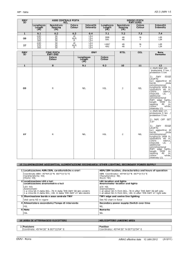
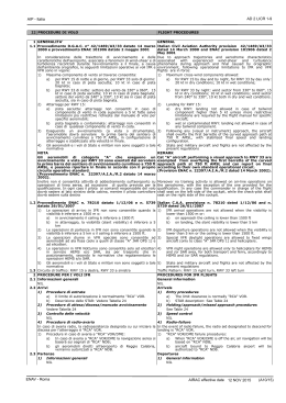
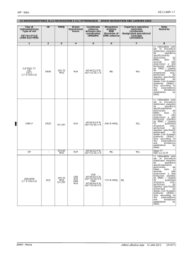
AD 2 LIRF 1-1
AIP - Italia
1 LIRF
Indicatore di località
Location indicator
ROMA/Fiumicino
Nome dell’ Aeroporto
Aerodrome name
2 DATI AMMINISTRATIVI E GEOGRAFICI DELL’AEROPORTO
AERODROME GEOGRAPHICAL AND ADMINISTRATIVE DATA
1 Coordinate ARP
41°48'01''N 012°14'20''E
2 Direzione e distanza dalla città
18.9 NM WSW da Roma
3 Elevazione/Temperatura di riferimento
14 FT / 28.3 °C
4 Ondulazione del geoide
157.6 FT
5 Variazione magnetica/Variazione annuale
2° E (2005.0) / 5'E
6 Autorità amministrativa aeroportuale
ENAC - Direzione Sistema Aeroporti Lazio
Aeroporto "Leonardo Da Vinci"
00054 Fiumicino (Roma)
Tel. +39 06 65953139 Fax +39 06 65010844
E-mail: [email protected]
Esercente
SOC. Aeroporti di Roma S.p.A.
Tel. +39 06 65951
WEB: www.adr.it
Autorità ATS
ENAV S.p.A. - Centro Aeroportuale Fiumicino
Tel: +39 06 65650201; fax +39 06 65650251
e-mail: [email protected]
7 Tipo di traffico consentito (IFR/VFR)
IFR
8 Note
1)
Codice di riferimento ANNEX 14 per infrastrutture di volo: 4F
ARP coordinates
41°48'01''N 012°14'20''E
Direction and distance from city
18.9 NM WSW from Rome
Elevation/Reference temperature
14 FT / 28.3 °C
Geoid undulation
157.6 FT
Magnetic variation/Annual change
2° E (2005.0) / 5'E
Aerodrome administration authority
ENAC - Direzione Sistema Aeroporti Lazio
Aeroporto "Leonardo Da Vinci"
00054 Fiumicino (Roma)
Tel. +39 06 65953139 Fax +39 06 65010844
E-mail: [email protected]
Aerodrome operator
SOC. Aeroporti di Roma S.p.A.
Tel. +39 06 65951
WEB: www.adr.it
ATS authority
ENAV S.p.A. - Centro Aeroportuale Fiumicino
Tel: +39 06 65650201; fax +39 06 65650251
e-mail: [email protected]
Type of traffic permitted (IFR/VFR)
IFR
Remarks
1)
Ref code ANNEX 14 flight infrastructure: 4F
3 ORARIO DI SERVIZIO
OPERATIONAL HOURS
1 Amministrazione aeroportuale
H24
2 Dogana e immigrazione
H24
3 Servizio sanitario
H24
4 AIS Briefing Office
H24 ARO CBO ROMA
5 ARO
H24 ARO CBO ROMA
6 METEO Briefing Office
H24 ARO CBO ROMA
7 ATS
H24
8 Rifornimento
H24
9 Handling
H24
10 Servizi di sicurezza
H24
11 De-icing
H24
12 Note
1)
ARO CBO ROMA: vedi GEN 3.1
Aerodrome Administration
H24
Customs and immigration
H24
Health and sanitation
H24
AIS Briefing Office
H24 ARO CBO ROMA
ARO
H24 ARO CBO ROMA
METEO Briefing Office
H24 ARO CBO ROMA
ATS
H24
Fuelling
H24
Handling
H24
Security
H24
De-icing
H24
Remarks
1)
ARO CBO ROMA: see GEN 3.1
4 SERVIZI DI SUPPORTO ED ATTREZZATURE
HANDLING SERVICES AND FACILITIES
1 Attrezzatura di carico e scarico merci
Trattori-Elevatori-Carrelli-Autogrù 25 tonellate
2 Tipi di carburante/Olio
JET A1, CHEVRON HY JET - IV / ETO 2380, MOBILJET oil II
3 Capacità di rifornimento
Impianto statico ed autobotti
4 Sistema de-icing
Servizio fornito da Aeroporti di Roma S.p.A.(ADR) a tutti i tipi di
aeromobile con 6 attrezzature semoventi de-icer. Liquido utilizzato
acqua calda e fluido tipo II (miscelato con diverse percentuali
conformemente alla procedura in vigore).
Il servizio de/anti-icing è prestato da ADR a seguito di richiesta da
parte del vettore o suo rappresentante all'ufficio ADR Controllo Voli.
Le operazioni de-icing sono svolte sulla piazzola di sosta aeromobili.
Il personale ADR non effettua il post de-icing check.
Cargo-handling facilities
Tractors-Elevators-Trolleys-Crane Vehicles 25 ton
Fuel/Oil types
JET A1, CHEVRON HY JET - IV / ETO 2380, MOBILJET oil II
Fuelling capacity
Underground tank installations and various tank trucks
De-icing facilities
Service performed by Aeroporti di Roma S.p.A. (ADR) for all types
of aircraft, equipment used 6 de-icer. Service performed with hot
water and type II fluid (different percentage available according to
airport procedure).
The de/anti-cing service is provided by ADR after carrier
communicates the request to ADR Flight Control office, directly or
by its representative. The de-icing operations are carried out on the
stand. ADR staff does not perform the post de-icing check.
ENAV - Roma
AIRAC effective date
07 JAN 2016
(A12/15)
AD 2 LIRF 1-2
AIP - Italia
5 Hangar per aeromobili in transito
NIL
6 Servizio riparazioni per aeromobili in transito
Piccole riparazioni
7 Note
1)
Rifornimento a clienti con contratto; il pagamento dovrà essere
effettuato con carnet validi e riconosciuti, o in contanti in valuta
internazionale. La ESSO accetta carte di credito American
Express
2)
Attrezzature/procedure regolarmente gestite da B.C.U. (Bird
Control Unit):
a)
5/7 ispezioni programmate del sedime al giorno
b)
N.2 impianti “Digital Bird Dispersal System” sulle
autovetture del B.C.U.
c)
N.1 impianto fisso “Digital Bird Dispersal System” sulle
piste 16R/34L e 07/25
d)
N.2 impianti fissi di “Sistemi acustici ad alte frequenze”
sulle piste 07/25 e 16R/34L
e)
N.115 “Cannoncini a gas” fissi sulle piste 07/25, 16L/34R e
16R/34L
f)
Sistema di telecamere radiocontrollate su tutte le piste
Hangar space for visiting aircraft
NIL
Repair facilities for visiting aircraft
Minor repairs
Remarks
1)
Refuelling only to subscribers; payment by valid and accepted
carnet or cash if in international currency. ESSO Company
accepts American Express credit cards
2)
Devices/procedures regularly run by B.C.U. (Bird Control
Unit):
a)
Runways’ patrolling 5/7 times per day
b)
N.2 “Digital Bird Dispersal System” (distress-call) devices
operating on the vehicles of the B.C.U.
c)
N.1 static “Digital Bird Dispersal System” present along
runways 16R/34L and 07/25
d)
N.2 static “High Frequencies Sound System” devices
along runways 07/25 and 16R/34L
e)
N.115 remote-controlled propane “Gas cannons” along
runways 07/25, 16L/34R and 16R/34L
f)
Remote-controlled video cameras’ system operating on
all the runways
5 SERVIZI PER I PASSEGGERI
PASSENGER FACILITIES
1 Alberghi
In aeroporto, a Roma città e Ostia Lido
2 Ristoranti
4450 pasti; HR: 0700-2400
3 Trasporti
Ferrovia - Autolinee - Taxi
4 Servizio medico
Infermeria - Pronto soccorso di linea ed in zona piste
Medici - Infermieri - Ambulanze - Ospedali ad Ostia e Roma
5 Banca e ufficio postale
In Aerostazione
6 Ufficio turistico
In Aerostazione
7 Note
1)
Presenti in aerostazione anche due Farmacie ed un deposito
bagagli
Hotels
In airport, Rome and Ostia Lido
Restaurants
4450 meals. HR: 0700/2400
Transportation
Railway - Bus - Taxi
Medical facilities
Infirmary - First aid treatment on RWY areas - Doctors - Nurses Ambulances - Hospitals in Ostia and Rome
Bank and Post office
In Airport
Touristic office
In Airport
Remarks
1)
In airport there are also two pharmacies and one left luggage
facility
6 SERVIZI ANTINCENDIO E DI SOCCORSO
RESCUE AND FIRE FIGHTING SERVICES
1 Categoria servizio antincendio aeroportuale
CAT 10 ICAO
2 Equipaggiamento per il soccorso
Conforme 9 ICAO
3 Rimozione aeromobili in difficoltà
Recovery Kit per aeromobili fino a CAT 4E (B747)
4 Note
NIL
Aerodrome category for fire fighting
CAT 10 ICAO
Rescue equipment
Equal 9 ICAO
Capability for removal of disabled aircraft
Recovery Kit for aircraft up to CAT 4E (B747)
Remarks
NIL
7 DISPONIBILITA’
PISTE
STAGIONALE
E
SISTEMI
DI
PULITURA SEASONAL AVAILABILITY AND CLEARING
1 Equipaggiamenti di pulitura
Equipaggiamento ordinario e sgombero neve
2 Priorità
Pista 16R/34L - piazzale ovest - vie di rullaggio relative
3 Note
1)
Il coefficiente di attrito delle piste è misurato ogni 7 giorni
(standard ICAO), sulla pista 07/25, ogni 15 giorni. Il mezzo di
misurazione è il SFT (Surface Friction Tester). Il livello minimo
del coefficiente d’attrito, prima di considerare la pista scivolosa,
è 0.34. La rimozione dei residui gommosi è garantita per
mantenere il valore del coefficiente di attrito sopra 0.34. La
rimozione della neve è garantita come da “Piano Neve
Aeroportuale”.
Types of clearing equipment
Ordinary and snow removal equipment
Clearance priorities
RWY 16R/34L - Apron west side - relevant TWY
Remarks
1)
Friction Coefficient is measured every 7 days (ICAO standard),
every 15 days on RWY 07/25 by means of SFT (Surface
Friction Tester). Minimum friction level is 0.34, below this value
RWY pavement may be slippery when wet. Derubbering of
pavement will consequently be undertaken. Snow removal is
performed as detailed in the “Airport Snow Removal Plan”
8 DATI RELATIVI AI PIAZZALI, ALLE VIE DI RULLAGGIO ED APRONS, TAXIWAYS AND CHECK LOCATIONS DATA
ALLE PIAZZOLE PROVA
1 Superficie e resistenza dell’area di stazionamento
Piazzale
Superficie: NIL
Resistenza: PCN 70/R/B/W/U
AIRAC effective date
07 JAN 2016 (A12/15)
Apron surface and strength
Apron
Surface: NIL
Strength: PCN 70/R/B/W/U
ENAV - Roma
AD 2 LIRF 1-3
AIP - Italia
2 Larghezza, superficie e resistenza delle TWY
A
Larghezza: 30 M
Superficie: NIL
Resistenza: PCN 139/F/A/W/T
AA
Larghezza: 25 M
Superficie: NIL
Resistenza: PCN 140/F/A/W/T
AB
Larghezza: 25 M
Superficie: NIL
Resistenza: PCN 139/F/A/W/T
AC
Larghezza: 30 M
Superficie: NIL
Resistenza: PCN 140/F/A/W/T
AD-AE-AF
Larghezza: 25 M
Superficie: NIL
Resistenza: NIL
AG-AH
Larghezza: 30 M
Superficie: NIL
Resistenza: NIL
AK-AL
Larghezza: 30 M
Superficie: NIL
Resistenza: PCN 73/F/B/X/T
B
Larghezza: NIL
Superficie: NIL
Resistenza: PCN 73/F/B/X/T
NOTE larghezza:
30 M (tra TWY A e TWYL R)
23 M (tra TWYL R e TWY DM)
BA
Larghezza: 25 M
Superficie: NIL
Resistenza: PCN 140/R/D/W/T
BB
Larghezza: 30 M
Superficie: NIL
Resistenza: PCN 140/R/D/W/T
BC-BD-BE
Larghezza: 23 M
Superficie: NIL
Resistenza: PCN 73/F/B/X/T
BF-BG
Larghezza: 30 M
Superficie: NIL
Resistenza: PCN 73/F/B/X/T
C
Larghezza: 30 M
Superficie: NIL
Resistenza: PCN 83/F/A/W/T
CD-CE-CH-CL
Larghezza: 30 M
Superficie: NIL
Resistenza: NIL
D
Larghezza: NIL
Superficie: NIL
Resistenza: PCN 72/F/B/X/T
NOTE larghezza:
23 M (tra TWYL G e TWY DM)
25 M (tra TWY DM e TWY DL)
45 M (tra TWY DL e TWY DB)
25 M (tra TWY DB e TWY DA)
DA-DB-DC-DH-DK-DL-DM
Larghezza: 25 M
Superficie: NIL
Resistenza: NIL
DD-DE-DF-DG
Larghezza: 23 M
Superficie: NIL
Resistenza: NIL
3 Localizzazione/Elevazione ACL
NIL / NIL
4 Punto di controllo VOR/INS
NIL / Disponibile controllo INS agli stands
5 Note
1)
TWY BB disponibile per aeromobili CODE F
ENAV - Roma
TWY width, surface and strength
A
Width: 30 M
Surface: NIL
Strength: PCN 139/F/A/W/T
AA
Width: 25 M
Surface: NIL
Strength: PCN 140/F/A/W/T
AB
Width: 25 M
Surface: NIL
Strength: PCN 139/F/A/W/T
AC
Width: 30 M
Surface: NIL
Strength: PCN 140/F/A/W/T
AD-AE-AF
Width: 25 M
Surface: NIL
Strength: NIL
AG-AH
Width: 30 M
Surface: NIL
Strength: NIL
AK-AL
Width: 30 M
Surface: NIL
Strength: PCN 73/F/B/X/T
B
Width:NIL
Surface: NIL
Strength: PCN 73/F/B/X/T
RMKS width:
30M (between TWY A and TWYL R)
23 M (between TWYL R and TWY DM)
BA
Width: 25 M
Surface: NIL
Strength: PCN 140/R/D/W/T
BB
Width: 30 M
Surface: NIL
Strength: PCN 140/R/D/W/T
BC-BD-BE
Width: 23 M
Surface: NIL
Strength: PCN 73/F/B/X/T
BF-BG
Width: 30 M
Surface: NIL
Strength: PCN 73/F/B/X/T
C
Width: 30 M
Surface: NIL
Strength: PCN 83/F/A/W/T
CD-CE-CH-CL
Width: 30 M
Surface: NIL
Strength: NIL
D
Width:NIL
Surface: NIL
Strength: PCN 72/F/B/X/T
RMKS width:
23 M (between TWYL G and TWY DM)
25 M (between TWY DM and TWY DL)
45 M (between TWY DL andTWY DB)
25 M (between TWY DB and TWY DA)
DA-DB-DC-DH-DK-DL-DM
Width: 25 M
Surface: NIL
Strength: NIL
DD-DE-DF-DG
Width: 23 M
Surface: NIL
Strength: NIL
ACL location/Elevation
NIL / NIL
VOR/INS checkpoints
NIL / INS check available at the stands
Remarks
1)
TWY BB available for CODE F aircraft
AIRAC effective date
07 JAN 2016
(A12/15)
AD 2 LIRF 1-4
AIP - Italia
9 GUIDA AI MOVIMENTI A TERRA E SISTEMI DI CONTROLLO E SURFACE MOVEMENT GUIDANCE AND CONTROL SYSTEM AND
SEGNALAZIONE
MARKINGS
1 Segnale di identificazione stand aeromobili, linee guida per
TWY e sistemi di guida per parcheggio a vista negli stand
degli aeromobili
Segnaletica: conforme agli standard ICAO, tabelle di identificazione
degli stand di tipo rifrangente con caratteri gialli su fondo nero
Use of aircraft stand identification sign, TWY guide lines and
visual docking/parking guidance system of aircraft stands
Markings: ICAO standard, stands identification reflecting schedules
with yellow inscriptions on black back-ground
Linee guida per TWY: segnaletica orizzontale gialla continua, luci e TWY guide lines: continuous yellow horizontal sign, day and night
tabelle indicatrici diurne e notturne/luci interne
indication lights and signs/internal lights
Sistema di guida per parcheggio a vista: nose-in con guida ottica, Visual parking guiding system: optical guide nose-in, remotes with
remoti con segnaletica orizzontale
horizontal markings
2 Illuminazione e segnaletica per RWY e TWY
Vedi carta AD in vigore
3 Barre d’arresto
Vedi carta AD in vigore
4 Note
1)
Vedi carta AD e APD in vigore
10 OSTACOLI AEROPORTUALI
RWY and TWY markings and lights
See AD chart in force
Stop bars
See AD chart in force
Remarks
1)
See AD and APD charts in force
AERODROME OBSTACLES
Nelle aree di avvicinamento e decollo
In approach and take off areas
RWY e Area
interessata
RWY and Area
affected
a
1
Tipo di ostacolo
Elevazione
Segnaletica e Luci
Obstacle type
Elevation
Markings and Lights
b
Nell’area di circuitazione e all’interno
dell’aerodromo
In circling area and at aerodrome
2
Coordinate
Tipo di ostacolo
Coordinate
Coordinates
Elevazione
Coordinates
Segnaletica e Luci
Obstacle type
Elevation
Marking and Lights
c
a
b
Vedi AOC in vigore
See AOC in force
11 INFORMAZIONI METEOROLOGICHE
1 Ufficio METEO associato
UPM ROMA
2 Orario di servizio
H24
3 Ufficio responsabile preparazione TAF/Periodo di validità
UPM ROMA / 30H
4 Tipo di previsione per l’atterraggio/Intervallo di emissione
Previsioni TREND / 30'
5 Briefing e consultazione fornita
Briefing: ARO CBO ROMA, telefono
Consultazione: UPM ROMA, telefono
6 Documentazione di volo/Lingua usata
Carte, testi in linguaggio chiaro abbreviato
IT, EN
7 Carte e documentazione disponibili per consultazione
P, W, SWL
8 Mezzi aggiuntivi disponibili per l’informazione
Fax
9 Enti ATS destinatari delle informazioni
Fiume TWR, Roma ACC/FIC
10 Informazioni climatologiche e informazioni supplementari
1)
ARO CBO ROMA: vedi GEN 3.1
2)
UPM ROMA: vedi GEN 3.5
3)
Aeroporto occasionalmente interessato da fenomeni di wind
shear, più frequentemente nei mesi di marzo e novembre. La
gran parte degli eventi deriva da perturbazioni e venti intensi a
grande scala o da temporali. Gli eventi con vento da NNE di
intensità 15-25 kt prevalgono nei giorni con il cielo sereno;
quelli con vento da SE e da OSO nei giorni con cielo nuvoloso o
attività temporalesca
4)
Per il Servizio Osservazioni mediante Radar Meteo vedi GEN
3.5
AIRAC effective date
07 JAN 2016 (A12/15)
Note
Remarks
3
METEOROLOGICAL INFORMATION
Associated MET Office
UPM ROMA
Hours of service
H24
Office responsible for TAF preparation/Period of validity
UPM ROMA / 30H
Type of landing forecast/Interval of issuance
TREND forecast / 30'
Briefing and consultation provided
Briefing: ARO CBO ROMA, telephone
Consultation: UPM ROMA, telephone
Flight documentation/Language used
Charts, abbreviated plain language texts
IT, EN
Charts and other information available for briefing or
consultation
P, W, SWL
Supplementary
equipment
available
for
providing
information
Fax
ATS units provided with information
Fiume TWR, Roma ACC/FIC
Climatological information and additional information
1)
ARO CBO ROMA: see GEN 3.1
2)
UPM ROMA: see GEN 3.5
3)
Aerodrome occasionally affected by wind shear phenomena,
more frequently occurring in the months of March and
November. A great part of the events is due to meteorological
perturbations and intense large scale winds or to
thunderstorms. The episodes with wind from NNE with 15-25
kt intensity prevail in clear sky days; the ones with wind from
SE or WSW prevail in cloudy days or when thunderstorm
activity occurs
4)
For Ground-Based Weather Radar Service see GEN 3.5
ENAV - Roma
AD 2 LIRF 1-5
AIP - Italia
12 CARATTERISTICHE FISICHE DELLE PISTE
RUNWAY PHYSICAL CHARACTERISTICS
Designazione
NR RWY
Designation
QFU
Dimensioni RWY
Dimension of RWY
(M)
Resistenza e superficie di
RWY
Strength and surface of
RWY
1
2
3
4
07
068°
3307 x 45
PCN 73/F/B/X/T
Conglomerato bituminoso
Bituminous conglomerate
25
248°
3307 x 45
PCN 73/F/B/X/T
Conglomerato bituminoso
Bituminous conglomerate
16C
161°
3602 x 45
PCN 72/F/B/X/T
Conglomerato bituminoso
Bituminous conglomerate
34C
341°
3602 x 45
PCN 72/F/B/X/T
Conglomerato bituminoso
Bituminous conglomerate
16L
161°
3902 x 60
PCN 146/F/A/W/T
Conglomerato bituminoso
Bituminous conglomerate
34R
341°
3902 x 60
PCN 146/F/A/W/T
Conglomerato bituminoso
Bituminous conglomerate
16R
161°
3902 x 60
PCN 94/F/A/W/T
Conglomerato bituminoso
Bituminous conglomerate
34L
341°
3902 x 60
PCN 94/F/A/W/T
Conglomerato bituminoso
Bituminous conglomerate
Designazione
NR RWY
Designation
1
07
25
16C
34C
16L
34R
16R
34L
ENAV - Roma
Pendenza di
RWY-SWY
Slope
7
Vedi AOC in vigore
See AOC in force
Vedi AOC in vigore
See AOC in force
Vedi AOC in vigore
See AOC in force
Vedi AOC in vigore
See AOC in force
Vedi AOC in vigore
See AOC in force
Vedi AOC in vigore
See AOC in force
Vedi AOC in vigore
See AOC in force
Vedi AOC in vigore
See AOC in force
Coordinate THR
THR coordinates
--Coordinate RWY END
RWY END Coordinates
--Ondulazione Geoide THR
THR Geoid Undulation
5
41°48'02.22''N
012°14'12.55''E
----------------------------41°48'34.66''N
012°16'10.11''E
----------------------------157.6 FT
41°48'34.66''N
012°16'10.11''E
----------------------------41°47'57.56''N
012°13'55.71''E
----------------------------157.5 FT
41°50'15.31''N
012°15'42.37''E
----------------------------41°48'42.46''N
012°16'21.22''E
----------------------------157.6 FT
41°48'42.46''N
012°16'21.22''E
----------------------------41°50'15.31''N
012°15'42.37''E
----------------------------157.5 FT
41°50'45.49''N
012°15'41.38''E
----------------------------41°48'44.80''N
012°16'31.89''E
----------------------------157.6 FT
41°48'44.80''N
012°16'31.89''E
----------------------------41°50'45.49''N
012°15'41.38''E
----------------------------157.5 FT
41°48'55.86''N
012°13'34.91''E
----------------------------41°46'55.18''N
012°14'25.45''E
----------------------------157.8 FT
41°46'55.18''N
012°14'25.45''E
----------------------------41°48'55.86''N
012°13'34.91''E
----------------------------157.4 FT
THR ELEV, MAX TDZ ELEV
della RWY per APCH di
precisione
THR ELEV, MAX TDZ ELEV
of precision APCH RWY
6
6.9 FT / 7 FT
5.2 FT / 8 FT
8.3 FT / 8 FT
3.7 FT / 4 FT
13.8 FT / 13 FT
5.7 FT / 5 FT
6.6 FT / 7 FT
7.6 FT / 8 FT
Dimensioni SWY
SWY dimension
(M)
8
Dimensioni CWY
CWY dimension
(M)
9
Dimensioni strip
strip dimension
(M)
10
Dimensioni RESA
RESA dimension
(M)
11
NIL
60 x 150
3427 x 300
90 x 90
NIL
60 x 150
3427 x 300
90 x 90
200
200 x 150
3922 x 300
90 x 90
600
60 x 150
3922 x 300
90 x 90
NIL
60 x 150
4022 x 300
90 x 120
NIL
60 x 150
4022 x 300
90 x 120
NIL
60 x 150
4022 x 300
90 x 120
NIL
60 x 150
4022 x 300
90 x 120
AIRAC effective date
07 JAN 2016
(A12/15)
AD 2 LIRF 1-6
AIP - Italia
Designazione
NR RWY
Designation
1
OFZ
Obstacle free zone (OFZ)
12
Not applicable
Non applicabile
Sì
Yes
Si
Yes
Si
Yes
Si
Yes
Si
Yes
Si
Yes
Si
Yes
07
25
16C
34C
16L
34R
16R
34L
Note
Remarks
13
1) DTHR 415m
NIL
1) DTHR 600m
NIL
NIL
NIL
NIL
NIL
13 DISTANZE DICHIARATE
DECLARED DISTANCES
Designazione RWY
RWY designator
1
07
INT TAKE-OFF A
25
INT TAKE-OFF BC-BD
16C
INT TAKE-OFF 16C
INT TAKE-OFF CD
34C
16L
INT TAKE-OFF DB
34R
INT TAKE-OFF DK
16R
INT TAKE-OFF AC
34L
NOTE/REMARKS
TORA
(M)
2
3307
2890
3307
2485
3602
2825
2235
3002
3902
3620
3902
3540
3902
2948
3902
1)
2)
TODA
(M)
3
3367
2950
3367
2545
3802
3025
2435
3062
3962
3680
3962
3600
3962
3008
3962
1
APPROACH AND RUNWAY LIGHTING
AVVICINAMENTO
APPROACH
Lunghezza
Intensità
Length
Intensity
(M)
Tipo
Type
2.1
2.2
THR
VASIS
MEHT
(M)
TDZ
Lunghezza
Length
(M)
2.3
3
4.1
NIL
07
SALS
420
NIL
25
CAT I
900
6.6
THR
G
NIL
16C
CAT I
420
6.6
THR
G
NIL
34C
CAT I
420
6.6
THR
G
NIL
16L
CAT II III
900
6.6
THR
G
NIL
34R
CAT II III
900
6.6
THR
G
NIL
16R
CAT II III
900
6.6
THR
G
NIL
34L
CAT I
578
LIH
THR
G
NIL
07 JAN 2016 (A12/15)
PAPI
Colore
Colour
THR
G
AIRAC effective date
LDA
(M)
5
2892
3307
3002
3002
3902
3902
3902
3902
RWY 34C: Vedi tabella 20, item 1: “Atterraggi pista 34C”/See table 20, item 1: “Landing on RWY 34C”
Gli INT TAKE-OFF sono utilizzabili soltanto su richiesta del pilota o su richiesta della TWR previo benestare
del pilota/INT TAKE-OFF are usable only on pilot’s request or on TWR’s request, previous pilot’s agreement
14 LUCI DI AVVICINAMENTO E LUCI PISTA
RWY
ID
ASDA
(M)
4
3307
2890
3307
2485
3802
3025
2435
3602
3902
3620
3902
3540
3902
2948
3902
4.2
3°
lato sx
left side
3°
entrambi i lati
both sides
3°
lato sx
left side
3°
lato sx
left side
3°
entrambi i lati
both sides
3°
entrambi i lati
both sides
3°
entrambi i lati
both sides
3.5°
entrambi i
lati/both
sides
4.3
5
21.5
NIL
22.9
NIL
17.0
NIL
17.0
NIL
20.0
900
20.4
900
21.0
900
18.3
NIL
ENAV - Roma
AD 2 LIRF 1-7
AIP - Italia
RWY
ID
ASSE CENTRALE PISTA
RCL
Spaziatura
Colore
Spacing
Colour
(M)
Lunghezza
Length
(M)
1
07
25
16C
34C
16L
34R
16R
34L
Intensità
Intensity
6.1
416
1991
600
300
2407
600
300
6.2
15
15
15
15
15
15
15
6.3
R
W
W/R
R
W
W/R
R
6.4
6.6
6.6
6.6
6.6
6.6
6.6
6.6
NIL
NIL
NIL
NIL
NIL
NIL
NIL
NIL
3002
600
300
3002
600
300
3002
600
300
3002
600
300
15
15
15
15
15
15
15
15
15
15
15
15
W
W/R
R
W
W/R
R
W
W/R
R
W
W/R
R
6.6
6.6
6.6
6.6
6.6
6.6
6.6
6.6
6.6
6.6
6.6
6.6
RWY
ID
FINE PISTA
RWY END
Colore
Colour
Lunghezza
Length
(M)
BORDO PISTA
RWY EDGE
Spaziatura
Colore
Spacing
Colour
(M)
Intensità
Intensity
7.1
7.2
7.3
7.4
416
2291
600
60
60
60
R
W
Y
6.6
6.6
6.6
2707
600
60
60
W
Y
6.6
6.6
600
2402
600
2402
600
60
60
60
60
60
R
W
Y
W
Y
6.6
6.6
6.6
6.6
6.6
3302
600
60
60
W
Y
6.6
6.6
3302
600
60
60
W
Y
6.6
6.6
3302
600
60
60
W
Y
6.6
6.6
3302
600
60
60
W
Y
6.6
6.6
RTIL
CGL
Note
Remarks
12
NIL
APCH LGT: CAT I +
EFAS
SWY
Lunghezza
Length
(M)
Colore
Colour
1
07
8
R
9.1
NIL
9.2
NIL
10
NIL
11
NIL
25
R
NIL
NIL
NIL
NIL
16C
R
200
R
NIL
NIL
34C
R
865
R
NIL
NIL
NIL
NIL
APCH LGT: CAT II
III + EFAS
APCH LGT: CAT II
III + EFAS
APCH LGT: CAT I
16L
R
NIL
NIL
Si
Yes
Si
Yes
NIL
34R
R
NIL
NIL
NIL
NIL
16R
R
NIL
NIL
NIL
NIL
34L
R
NIL
NIL
NIL
NIL
15 ILLUMINAZIONE AGGIUNTIVA, ALIMENTAZIONE SECONDARIA OTHER LIGHTING, SECONDARY POWER SUPPLY
1 Localizzazione ABN/IBN, caratteristiche e orari
Coordinate ABN: 41°47'46''N 012°15'10''E
ABN caratteristiche: luce bianco/verde alternata
Orario: HN+/-30
2 Localizzazione LDI e luci
Localizzazione anemometro e luci
LDI: NIL
Anemometri:
1) 388 m dopo
2) 369 m dopo
3) 419 m dopo
4) 387 m dopo
5) 670 m dopo
6) 397 m dopo
THR
THR
THR
THR
THR
THR
25, 165 m lato destro RCL
16R, 182 m lato destro RCL
16L, 188 m lato sinistro RCL
34R, 183 m lato destro RCL
34L, 199 m lato destro RCL
16C, 220 m lato destro RCL
3 Illuminazione bordo e asse centrale TWY
Vedi carta AD
4 Alimentatore secondario/Tempo di intervento
Disponibile/Immediato
5 Note
NIL
16 AREA DI ATTERRAGGIO ELICOTTERI
1 Posizione
NIL
2 Elevazione
NIL
3 Dimensioni, superficie, resistenza, segnaletica
NIL
ENAV - Roma
ABN/IBN location, characteristics and hours of operation
ABN Coordinates: 41°47'46''N 012°15'10''E
ABN characteristics: revolving white/green alternating light
Hours: HN+/-30
LDI location and lights
Anemometer location and lights
LDI: NIL
Anemometers:
1) 388 m after
2) 369 m after
3) 419 m after
4) 387 m after
5) 670 m after
6) 397 m after
THR
THR
THR
THR
THR
THR
25, 165 m right side RCL
16R, 182 m right side RCL
16L, 188 m left side RCL
34R, 183 m right side RCL
34L, 199 m right side RCL
16C, 220 m right side RCL
TWY edge and centre line lighting
See AD chart
Secondary power supply/Switch over time
Available/Immediately
Remarks
NIL
HELICOPTERS LANDING AREA
Position
NIL
Elevation
NIL
Dimensions, surface, strength, marking
NIL
AIRAC effective date 21 AUG 2014
(A7/14)
AD 2 LIRF 1-8
AIP - Italia
4 Orientamento
NIL
5 Distanze dichiarate
NIL
6 Luci
NIL
7 Note
NIL
Bearing
NIL
Declared distances
NIL
Lighting
NIL
Remarks
NIL
17 SPAZIO AEREO ATS
ATS AIRSPACE
Designatore e limiti laterali
Designation and lateral limits
Limiti
verticali
Vertical
limits
Classificazione dello
spazio aereo
Airspace
classification
1
Roma Fiumicino ATZ
Cerchio di raggio/Circle of radius 5.0
NM
centrato su/centred on:
41°48'01''N 012°14'20''E
2
3
2000 FT
AGL
D
18 SERVIZI DI COMUNICAZIONE ATS
Nominativo
dell’unità ATS
Lingua
ATS unit call sign
Language
4
Fiume TWR
EN / IT
Altitudine di
transizione
Transition
altitude
Note
Remarks
5
6
6000 FT
1) WI Roma CTR
ATS COMMUNICATION FACILITIES
Servizio
Service
1
Emergenza
Emergency
Nominativo
Call sign
2
Frequenza MHZ
Frequency MHZ
3
Orario
Operational hours
4
NIL
121.500 MHZ
H24
NIL
APP
Roma Arrivi
Roma Arrivals
125.500 MHZ
H24
NIL
127.950 MHZ
Vedi note/See remarks
1) A discrezione ATC/ATC discretion
119.200 MHZ
Vedi note/See remarks
1) A discrezione ATC/ATC discretion
Roma Direttore
Roma Director
131.250 MHZ
Roma Partenze
Roma Departure
TWR
Fiume Delivery
H24
131.100 MHZ
Vedi note/See remarks
121.900 MHZ
Fiume GND
121.900 MHZ
122.125 MHZ
Fiume TWR
0600-2200 (0500-2100) NIL
130.900 MHZ
121.800 MHZ
118.700 MHZ
127.625 MHZ
Note
Remarks
5
NIL
1) A discrezione ATC/ATC discretion
1) Frequenza richiesta avviamento motori,
informazioni prevolo e rilascio autorizzazioni
ATC. Eccezionalmente la frequenza può
essere usata per controllo apparati radio di
bordo, solo quando tali controlli non possono
0600-2200 (0500-2100) essere
effettuati
sulla
frequenza
di
compagnia/starting-up request, pre flight
data and ATC clearances delivery frequency.
Exceptionally the frequency may be used for
radio checks, only when such checks cannot
be made on the Company frequency
2200-0600 (2100-0500) NIL
1) Sull'area Apron è fornito il servizio
informazioni in accordo a quanto previsto dal
regolamento di Scalo in vigore. Sull'area di
manovra è fornito il servizio ATC/On Apron
H24
Area, Information Service is provided,
according to the Local Civil Aviation
Regulation in force. On Manoeuvring area,
ATC service is provided
1) Sull'area Apron è fornito il servizio
informazioni in accordo a quanto previsto dal
regolamento di Scalo in vigore. Sull'area di
manovra è fornito il servizio ATC/On Apron
Area, Information Service is provided,
0600-2200 (0500-2100)
according to the Local Civil Aviation
Regulation in force. On Manoeuvring area,
ATC service is provided
2) A discrezione ATC/ATC discretion
NIL
1) Frequenza per operazioni su RWY 16L/34R
o RWY 16C/34C/Frequency for operations on
0600-2200 (0500-2100) RWY 16L/34R or RWY 16C/34C
H24
2) A discrezione ATC/ATC discretion
1) RWY: 16L/34R, 16C/34C, 07/25
ATIS
Fiume Arrival Information
Fiume Departure
Information
AIRAC effective date
21 AUG 2014 (A7/14)
120.175 MHZ
H24
126.125 MHZ
H24
121.850 MHZ
H24
2) Vedi note ATIS/see ATIS remarks 1 e/and 3
3) Disponibile anche telefonicamente al
numero/Also available via telephone at the
number + 39 06 65650318
1) RWY: 16R/34L
2) Vedi note ATIS/see ATIS remarks 1 e/and 3
1) RWY: Tutte/All
2) Vedi note ATIS/see ATIS remarks 2 e/and 3
ENAV - Roma
AD 2 LIRF 1-9
AIP - Italia
ATIS NOTE/REMARKS
1)
Quando sono in atto avvicinamenti ILS paralleli, il messaggio conterrà la seguente frase: “Avvicinamenti paralleli in corso. La pista in uso
16L e 16R o 34L e 34R o 16C e 16R sarà assegnata da Roma Radar”/Whenever parallel ILS approaches are in progress, the broadcast shall
contain the following sentence: “Parallel ILS approaches in progress. The RWY in use 16L and 16R or 34L and 34R or 16C and 16R shall be
assigned by Roma Radar”
2)
Informazioni relative alle procedure di assegnazione dell’autorizzazione ATC insieme all’autorizzazione alla messa in moto dei motori
NOTA: Quando la procedura di cui sopra è applicata il messaggio ATIS, oltre alle informazioni normali, conterrà anche la notizia dei ritardi/
Information regarding the procedures of ATC clearance assignment together with startup engine clearance
REMARK: When the above procedure is applied, ATIS message, besides normal information, shall also contain notice of delays
3)
In caso di avaria o manutenzione di una delle frequenze, sarà radiodiffuso un unico messaggio ATIS sulla frequenza disponibile con
l’aggiunta della seguente informazione: “ATIS SERVICE ON FREQUENCY … OUT OF SERVICE”. In tal caso Fiume Torre comunicherà ai piloti
la seguente frase: “TERMINAL INFORMATION AVAILABLE ON FREQUENCY …”/In the event of radio failure or maintenance of one of the
frequencies, an ATIS message will be broadcasted on the available frequency containing also the following information: “ATIS SERVICE ON
FREQUENCY ... OUT OF SERVICE”. In this case pilots will be advised by Fiume TWR as follows: “TERMINAL INFORMATION AVAILABLE ON
FREQUENCY …”
19 RADIOASSISTENZE ALLA NAVIGAZIONE E ALL’ATTERRAGGIO
Tipo di
radioassistenza
Type of aid
ID
FREQ
Orario
Operational
hours
Coordinate
antenna
Antenna site
coordinates
(WGS84)
Elevazione
antenna
DME
Elevation of
DME antenna
2
3
4
5
CAT di/of ILS
(VAR ILS/VOR)
1
TVOR/DME
(2° E-2005.0)
NDB
RADIO NAVIGATION AND LANDING AIDS
CMP
CMP
111.40
MHZ
CH 51X
301.50
KHZ
TVOR
H24
DME
H24
H24
TVOR
42°07'25.8''N
012°22'53.5''E
DME
42°07'25.5''N
012°22'53.2''E
42°07'29.8''N
012°22'49.0''E
Copertura operativa
nominale
Limitazioni
Designated operational
coverage
Limitations
Note
Remarks
6
7
8
437 M AMSL
Altri Settori/other Sectors:
25 NM/25000 FT
Settore/Sector NW: 70 NM/
25000 FT
limitazioni a/limitations at
25 NM
150°/220° MRA 3000 FT
220°/150° MRA 6000 FT
1) MAINT:
secondo FRI di ogni
mese/second
FRI
each month 08001000 (0700-0900)
NIL
50 NM
limitazioni oltre/limitations
beyond 20 NM
150°/220° MRA 3000 FT
220°/150° MRA 6000 FT
1) MAINT:
secondo
THU
di
ogni mese/second
THU each month
0800-1000 (07000900)
1) HR: operativo
solo con pista 34C
in
uso/Operative
only with RWY 34C
in use
ILS RWY 34C
LOC
CAT I
(2° E-2005.0)
FCC
108.50
MHZ
vedi note/see
remarks
41°50'53.3''N
012°15'26.4''E
NIL
NIL
2) Operativo sulla
stessa
frequenza
dell'ILS della pista
16C/Operative
on
ILS
RWY
16C
frequency
3)
Fascio
posteriore
non
utilizzabile/Back
beam not usable
1) HR: operativo
solo con pista 34C
in
uso/Operative
only with RWY 34C
in use
DME
FCC
CH 22X
vedi note/see
remarks
41°49'27.1''N
012°15'54.4''E
6 M AMSL
25 NM/10000 FT
2) Operativo sulla
stessa
frequenza
del
DME
'FNN'/
Operative on same
DME
'FNN'
frequency
3) Indicazione zero
alla THR RWY34C/
Zero
range
indication at THR
RWY 34C
4)
DME
non
utilizzabile lungo la
pista/DME
not
usable along the
RWY
ENAV - Roma
AIRAC effective date
07 JAN 2016
(A12/15)
AD 2 LIRF 1-10
Tipo di
radioassistenza
Type of aid
AIP - Italia
ID
FREQ
Orario
Operational
hours
Coordinate
antenna
Antenna site
coordinates
(WGS84)
Elevazione
antenna
DME
Elevation of
DME antenna
Copertura operativa
nominale
Limitazioni
Designated operational
coverage
Limitations
2
3
4
5
6
7
CAT di/of ILS
(VAR ILS/VOR)
1
Note
Remarks
8
1) HR: operativo
solo con pista 34C
in
uso/operative
only with RWY 34C
in use
GP
-
329.90
MHZ
vedi note/see
remarks
41°48'54.2''N
012°16'22.0''E
NIL
2) Operativo sulla
stessa
frequenza
dell'ILS della pista
16C/Operative
on
same ILS RWY 16C
frequency
NIL
Slope 3°
RDH:17.00 M
L
FE
354.00
KHZ
ILS RWY 25
LOC
CAT I
(2° E-2005.0)
FEE
110.15
MHZ
H24
41°49'53.1''N
012°21'04.0''E
NIL
H24
41°47'55.0''N
012°13'46.5''E
NIL
H24
41°48'36.3''N
012°15'54.0''E
8 M AMSL
H24
41°48'35.8''N
012°15'54.5''E
NIL
DME
FEE
GP
-
334.25
MHZ
OM
-
75.00
MHZ
H24
41°49'52.8''N
012°21'02.8''E
MM
-
75.00
MHZ
H24
L
FN
421.00
KHZ
H24
CH 38Y
25 NM
limitazioni
25 NM
040°/120°
120°/300°
300°/040°
a/limitations
MRA 4500 FT
MRA 1500 FT
MRA 2500 FT
at 1) MAINT
primo TUE di ogni
mese/first TUE each
month 0800-1000
(0700-0900)
1) Fascio posteriore
non
utilizzabile/
Back
beam
not
usable
NIL
limitazioni
25 NM
080°/120°
120°/260°
260°/080°
a/limitations
MRA 4500 FT
MRA 2000 FT
MRA 4000 FT
at
NIL
NIL
Slope 3°
RDH:17.70 M
NIL
NIL
1)
Temporaneamente
non
utilizzabile/
Temporarily
unserviceable
41°48'44.5''N
012°16'47.1''E
NIL
NIL
NIL
41°54'38.5''N
012°14'04.6''E
NIL
25 NM
limitazioni a/limitations
25 NM
120°/300° MRA 1500 FT
300°/120° MRA 7500 FT
1) MAINT:
at quarto TUE di ogni
mese/fourth
TUE
each month 08001000 (0700-0900)
1) Operativo solo
con pista 16C in
uso/operative only
with RWY 16C in
use
ILS RWY 16C
LOC
CAT I
(2° E-2005.0)
FNN
108.50
MHZ
vedi note/see
remarks
41°48'13.3''N
012°16'33.6''E
NIL
NIL
2) Operativo sulla
stessa
frequenza
dell'ILS della pista
34C/Operative
on
same
ILS RWY
34C frequency
3) Fascio posteriore
non
utilizzabile/
back
beam
not
usable
1) Operativo solo
con pista 16C in
uso/Operative only
with RWY 16C in
use
DME
FNN
CH 22X
vedi note/see
remarks
41°49'27.1''N
012°15'54.4''E
6 M AMSL
NIL
2) Operativo sulla
stessa
frequenza
del
DME
'FCC'/
Operative on same
DME
'FCC'
frequency
3) Indicazione zero
alla THR RWY16C/
Zero
range
indication at THR
RWY16C
4)
DME
non
utilizzabile lungo la
pista/DME
not
usable along the
RWY
AIRAC effective date
07 JAN 2016 (A12/15)
ENAV - Roma
AD 2 LIRF 1-11
AIP - Italia
Tipo di
radioassistenza
Type of aid
ID
FREQ
Orario
Operational
hours
Coordinate
antenna
Antenna site
coordinates
(WGS84)
Elevazione
antenna
DME
Elevation of
DME antenna
Copertura operativa
nominale
Limitazioni
Designated operational
coverage
Limitations
2
3
4
5
6
7
CAT di/of ILS
(VAR ILS/VOR)
1
Note
Remarks
8
1) Operativo solo
con pista 16C in
uso/operative only
with RWY 16C in
use
GP
-
329.90
MHZ
vedi note/see
remarks
41°50'03.3''N
012°15'41.7''E
NIL
2) Operativo sulla
stessa
frequenza
dell'ILS della pista
34C/Operative
on
same ILS RWY 34C
frequency
NIL
Slope 3°
RDH:17.00 M
DVOR/DME
(2° E-2005.0)
FRS
115.60
MHZ
CH 103X
DVOR
H24
DME
H24
DVOR
41°38'33.1''N
013°17'32.5''E
DME
41°38'33.3''N
013°17'32.0''E
189 M AMSL
L
FRS
371.00
KHZ
H24
41°38'37.8''N
013°17'22.8''E
NIL
ILS RWY 34R
LOC
CAT I
(2° E-2005.1)
FSS
111.55
MHZ
H24
41°50'58.2''N
012°15'36.1''E
NIL
H24
41°48'56.4''N
012°16'34.8''E
7 M AMSL
H24
41°48'56.2''N
012°16'34.2''E
NIL
DME
FSS
GP
-
OM
MM
-
-
CH 52Y
332.75
MHZ
75.00
MHZ
H24
75.00
MHZ
H24
41°45'02.5''N
012°18'07.3''E
NIL
41°48'16.3''N
012°16'43.5''E
NIL
40 NM/25000 FT
limitazioni entro/limitations
within 15 NM
RDL 267 MRA 9000 FT
limitazioni entro/limitations
within 23 NM
RDL 272 MRA 13000 FT
limitazioni a/limitations at
40 NM
080°/160° MRA 10000 FT
160°/230° MRA 20000 FT
230°/280° MRA 28000 FT
280°/310° MRA 6000 FT
310°/345° MRA 13000 FT
345°/080° MRA 21000 FT
25 NM
limitazioni
25 NM
060°/120°
120°/140°
140°/330°
330°/060°
a/limitations
MRA
MRA
MRA
MRA
8000 FT
6000 FT
9000 FT
11000 FT
at 1) MAINT:
primo THU di ogni
mese/first
THU
each month 10001200 (0900-1100)
1) Fascio posteriore
non
utilizzabile/
Back
beam
not
usable
NIL
limitazioni
25 NM
080°/100°
100°/290°
290°/080°
1) MAINT:
primo THU di ogni
mese/first
THU
each month 10001200 (0900-1100)
a/limitations
at
MRA 4500 FT
MRA 2000 FT
MRA 4000 FT
NIL
Slope 3°
RDH:17.50 M
NIL
1) Senza controllo a
distanza/No remote
control
NIL
2) Fuori servizio/
out of service
NIL
L
FW
345.00
KHZ
H24
41°52'51.1''N
012°11'55.6''E
NIL
25 NM
limitazioni
25 NM
070°/130°
130°/300°
300°/330°
330°/350°
350°/070°
ILS RWY 16L
LOC
CAT IIIB
(2° E-2005.0)
IFLL
108.10
MHZ
H24
41°48'32.3''N
012°16'37.1''E
NIL
limitazioni
17 NM MRA
limitazioni
25 NM MRA
H24
41°50'37.2''N
012°15'52.8''E
10 M AMSL
NIL
a/limitations
MRA
MRA
MRA
MRA
MRA
4000
2000
6000
7500
6000
at
FT
FT
FT
FT
FT
a/limitations
3000 FT
a/limitations
4000 FT
25 NM/10000 FT
limitazioni a/limitations
25 FT
040°/090° MRA 5000 FT
090°/140° MRA 6000 FT
140°/300° MRA 2000 FT
300°/040° MRA 3000 FT
1) MAINT:
primo THU di ogni
mese/first
THU
each month 08001000 (0700-0900)
at 1) Fascio posteriore
non
utilizzabile/
at Back
beam
not
usable
at
DME
IFLL
GP
-
334.70
MHZ
H24
41°50'37.0''N
012°15'51.8''E
NIL
NIL
Slope 3°
RDH:17.08 M
OM
-
75.00
MHZ
H24
41°54'37.3''N
012°14'04.9''E
NIL
NIL
NIL
MM
-
75.00
MHZ
H24
41°51'14.0''N
012°15'29.4''E
NIL
NIL
NIL
ILS RWY 16R
LOC
CAT IIIB
(2° E-2005.0)
IFRR
109.75
MHZ
H24
41°46'43.0''N
012°14'30.5''E
NIL
NIL
1) Fascio posteriore
non
utilizzabile/
Back
beam
not
usable
ENAV - Roma
CH 18X
AIRAC effective date
NIL
07 JAN 2016
(A12/15)
AD 2 LIRF 1-12
Tipo di
radioassistenza
Type of aid
AIP - Italia
ID
FREQ
Orario
Operational
hours
Coordinate
antenna
Antenna site
coordinates
(WGS84)
Elevazione
antenna
DME
Elevation of
DME antenna
2
3
4
5
6
CAT di/of ILS
(VAR ILS/VOR)
1
H24
41°48'44.0''N
012°13'33.0''E
NIL
NIL
Slope 3°
RDH:17.50 M
-
75.00
MHZ
H24
41°52'46.5''N
012°11'57.9''E
NIL
NIL
NIL
-
75.00
MHZ
H24
41°49'37.7''N
012°13'17.3''E
NIL
NIL
NIL
OM
MM
IFSW
DME
IFSW
GP
-
VOR/DME
(2° E-2010.0)
AIRAC effective date
at
333.05
MHZ
-
NDB
8
8 M AMSL
GP
VOR/DME
(2° E-2005.1)
7
25 NM/10000 FT
limitazioni a/limitations
25 NM
080°/130° MRA 5000 FT
130°/300° MRA 3000 FT
300°/080° MRA 4000 FT
41°48'43.7''N
012°13'31.7''E
IFRR
VOR/DME
(2° E-2005.0)
Note
Remarks
H24
DME
ILS RWY 34L
LOC
CAT I
(2° E-2005.0)
Copertura operativa
nominale
Limitazioni
Designated operational
coverage
Limitations
LAT
OST
OST
ROM
CH 34Y
108.90
MHZ
H24
41°49'06.8''N
012°13'30.3''E
NIL
H24
41°47'03.4''N
012°14'14.7''E
7 M AMSL
329.30
MHZ
H24
41°47'03.6''N
012°14'16.2''E
NIL
111.20
MHZ
CH 49X
VOR
H24
DME
H24
VOR
41°32'28.0''N
012°55'05.0''E
DME
41°32'27.9''N
012°55'04.4''E
CH 26X
114.90
MHZ
CH 96X
VOR
H24
DME
H24
VOR
41°48'13.6''N
012°14'15.1''E
DME
41°48'14.0''N
012°14'14.9''E
327.00
KHZ
H24
41°48'18.6''N
012°14'11.1''E
110.80
MHZ
CH 45X
VOR
H24
DME
H24
VOR
41°48'16.5''N
012°35'17.1''E
DME
41°48'16.5''N
012°35'17.1''E
07 JAN 2016 (A12/15)
NIL
1) Fascio posteriore
limitazioni oltre/limitations non
utilizzabile/
beyond 17 NM MRA 3000 FT back
beam
not
usable
25 NM/10000 FT
limitazioni a/limitations
25 NM
080°/100° MRA 4500 FT
100°/180° MRA 2000 FT
180°/260° NU
260°/290° MRA 2000 FT
290°/080° MRA 4000 FT
at
NIL
Slope 3.5°
RDH:17.50 M
NIL
24 M AMSL
60 NM/25000 FT
limitazioni a/limitations at 1) MAINT:
25 NM
Primo MON di ogni
010°/100° NU
mese: / first MON
100°/130° MRA 5000 FT
each month:
130°/290° MRA 2500 FT
0800-1000 (0700290°/330° MRA 5000 FT
0900)
330°/010° MRA 10000 FT
11 M AMSL
Settore/sector NW-N: 80
NM/50000FT
altri settori/others sectors:
150 NM/50000 FT
limitazioni a/limitations at
20 NM
000°/030° MRA 3000 FT
030°/120° MRA 2500 FT
120°/310° MRA 2000 FT
310°/360° MRA 3000 FT
limitazioni a/limitations at
40 NM
000°/070° MRA 6000 FT
070°/120° MRA 7500 FT
120°/310° MRA 3000 FT
310°/360° MRA 6000 FT
limitazioni oltre/limitations
beyond
60
NM
entro/
limitations within 80 NM
RDL 219 MRA 11000 FT
limitazioni oltre/limitations
beyond 80 NM
RDL 219 MRA 15000 FT
RDL 249 MRA 13000 FT
limitazioni entro/limitations
within 90 NM
RDL 177 MRA 10000 FT
limitazioni oltre/limitations
beyond
90
NM
entro/
limitations within 120 NM
RDL 177 MRA 16000 FT
limitazioni oltre/limitations
beyond 120 NM
RDL 177 NU
NIL
114 M AMSL
1) MAINT:
primo WED di ogni
mese/first
WED
each month 07000900 (0600-0800)
2) RDL 199: COV
ridotta a/reduced to
100 NM
50 NM
limitazioni a/limitations at
30 NM
340°/040° MRA 7000 FT
limitazioni oltre/limitations
beyond 30 NM
340°/040° NU
limitazioni a/limitations at
50 NM
040°/160° MRA 10000 FT
160°/285° MRA 2000 FT
285°/340° MRA 6000 FT
1) MAINT:
secondo MON di
ogni mese/second
MON each month
0800-1000 (07000900)
40 NM
limitazioni
40 NM
000°/045°
045°/080°
080°/170°
170°/360°
NIL
a/limitations
MRA
MRA
MRA
MRA
8000 FT
9500 FT
16000 FT
5000 FT
at
ENAV - Roma
AD 2 LIRF 1-13
AIP - Italia
Tipo di
radioassistenza
Type of aid
ID
FREQ
Orario
Operational
hours
Coordinate
antenna
Antenna site
coordinates
(WGS84)
Elevazione
antenna
DME
Elevation of
DME antenna
2
3
4
5
CAT di/of ILS
(VAR ILS/VOR)
1
VOR/DME
(2° E-2005.0)
NDB
NDB
TAQ
TAQ
URB
111.80
MHZ
CH 55X
312.00
KHZ
285.00
KHZ
20 REGOLAMENTI DEL TRAFFICO LOCALE
VOR
H24
DME
H24
H24
H24
VOR
42°12'54.2''N
011°43'57.4''E
DME
42°12'54.2''N
011°43'57.4''E
42°12'50.2''N
011°43'43.9''E
41°56'40.9''N
012°29'24.2''E
Copertura operativa
nominale
Limitazioni
Designated operational
coverage
Limitations
Note
Remarks
6
7
8
23 M AMSL
40 NM/25000 FT
limitazioni oltre/limitations
beyond 19 NM
RDL 115 MRA 8000 FT
limitazioni a/limitations at
40 NM
000°/140° MRA 10000 FT
140°/360° MRA 6000 FT
1) MAINT:
terzo THU di ogni
mese/third
THU
each month 09301100 (0830-1000)
NIL
50 NM
limitazioni
40 NM
120°/280°
280°/330°
330°/120°
1) MAINT:
terzo WED di ogni
mese/third
WED
each month 08001100 (0700-1000)
NIL
30 NM
limitazioni oltre/limitations
beyond 8 NM
140°/190° NU
limitazioni a/limitations at
25 NM
000°/050° MRA 5000 FT
050°/120° MRA 7000 FT
120°/140° MRA 10000 FT
190°/360° MRA 2000 FT
a/limitations
at
MRA 5000 FT
MRA 6000 FT
NU
1) MAINT:
quarto/fourth
FRI
di/of
FEB,
MAY,
AUG, NOV 08301030 (0730-0930)
LOCAL TRAFFIC REGULATIONS
1 Uso preferenziale delle piste
Runway preferential use
1) Generalità
1) General
Le piste in uso per atterraggi e decolli saranno scelte dall’ATC,
Runway in use for take-off and landing will be selected by
secondo un sistema preferenziale di piste.
ATC, according to preferential runway system, based on the
Tale sistema si basa sui seguenti principi:
following principles:
a)
Atterraggi e decolli avverranno su piste diverse
a)
Different runways will be used for take-off and landing
b)
Per gli atterraggi sarà scelta, a preferenza, una pista
b)
A runway provided with ILS will be preferred for landing
assistita da ILS
Criteri di selezione delle piste e loro uso
Criteria for runway selection and their use
a)
Configurazione di pista preferenziale:
a)
Preferential RWY configuration:
RWY 25 per i decolli
RWY 25 for take-off
RWY 16L per gli atterraggi
RWY 16L for landing
RWY 16R/34L è usata a discrezione ATC come pista
RWY 16R/34L is used on ATC discretion as parallel
parallela per gli atterraggi
RWY for landing
b)
Aeromobili in partenza che richiedono per il decollo una
b)
Should departing aircraft require for take-off a RWY
lunghezza maggiore di quella della RWY 25, possono usare
longer than RWY 25, pilots may request RWY 16R/34L
RWY 16R/34L con orario 0500-2200 (0400-2100) e RWY
during HR 0500-2200 (0400-2100) and RWY 16L/34R
16L/34R con orario HR 2200-0500 (2100-0400)
during HR 2200-0500 (2100-0400)
c)
Al fine di cambiare la configurazione delle piste da quella
c)
In order to change RWY configuration from the
preferenziale, l’ATC considererà i seguenti punti:
preferential one, ATC will consider the follwing items:
disponibilità di piste e vie di rullaggio
RWY and TWY availability
procedure di avvicinamento strumentale e disponibilità
instrument approach procedures and other
di aiuti all’avvicinamento e all’atterraggio
approach and landing aids’ availability
condizioni meteorologiche significative
significant meteorological conditions
componenti di vento, se costantemente eccedenti le
wind components if steadily exceeding following
seguenti misurazioni sulla pista RWY 16L/34R (o RWY
speed measured on RWY 16L/34R (or RWY 25 in
25 in caso di avaria dell’anemometro), che non sono
case of anemometer failure), which are not to be
da intendere come un limite operativo ma come una
intended as an operational limitation but as a
linea guida per l’ATC per la selezione delle piste:
guideline for ATC when selecting RWY in use:
- 30kt di compomente stabile di vento al traverso
- 30kt steady cross wind component (gusts
(raffiche escluse)
excluded)
- 10kt di componente stabile di vento in coda (raffiche
- 10kt steady tail wind component (gusts excluded)
escluse)
d)
Se la pista scelta dall’ATC non fosse ritenuta idonea alle
d)
When the runway selected by ATC is considered not
operazioni desiderate, i piloti potranno richiedere
suitable for the desired operation, pilots may request
l’autorizzazione ad usare un’altra pista; in tal caso
permission to use a different runway; in such a case the
l’aeromobile potrà essere soggetto a ritardi
aircraft may be subject to delay
e)
Allo scopo di contenere i tempi di attesa al decollo e
e)
In order to minimize delays and keep taxiways as clear
l’occupazione delle vie di rullaggio, sono istituite le
as possible, intersection take-off are established to be
intersection take-off che possono essere utilizzae per il
used on pilot’s request, or assigned by TWR previous
decollo su richiesta dei piloti, o della TWR previo consenso
pilot’s agreement (see declared distance AOC type A)
dei piloti (vedere distanze dichiarate AOC tipo A)
f)
RWY 16R/34L chiusa a tutte le operazioni ogni sabato HR
f)
RWY 16R/34L closed to all operations every Saturday HR
2230 - 0030 (2130 - 2330) per controllo a terra dell’ ILS,
2230 – 0030 (2130 – 2330), due to ILS ground check,
condizioni meteo e/o operative permettendo
weather and/or operative conditions permitting
g)
RWY 16L/34R chiusa a tutte le operazioni ogni domenica HR
g)
RWY 16L/34R closed to all operations every Sunday HR
2230 - 0030 (2130 - 2330) per controllo a terra dell’ ILS,
2230 – 0030 (2130 – 2330), due to ILS ground check,
condizioni meteo e/o operative permettendo
weather and/or operative conditions permitting
2) RWY 16C/34C
2) RWY 16C/34C
La pista 16C/34C è di fatto identificata ed utilizzata come TWY D
Former RWY 16C/34C is actually identified and used as TWY D
(relativa Carta d’Aerodromo AD 2 LIRF 2-1)
(relevant AD Chart AD 2 LIRF 2-1)
In circostanze particolari (es. lavori di manutenzione sulla pista
In special circumstances (e.g. RWY 16L/34R maintenance
works) the above TWY D might be used as RWY with physical
16L/34R) tale TWY D potrà essere riutilizzata come pista con le
characteristics, markings and signs as listed in AD 2 LIRF 1-1
caratteristiche fisiche e di segnaletica riportate in AD 2 LIRF 1-1 e
(relevant AD Chart AD 2 LIRF 2-3) and following.
seguenti (relativa Carta d’Aerodromo AD 2 LIRF 2-3) con la
Consequently RWY 16L/34R will be closed
contestuale chiusura della pista 16L/34R
ENAV - Roma
18 FEB 2016
(2/16)
AD 2 LIRF 1-14
3)
AIP - Italia
Tale evento verrà preannunciato con specifico NOTAM
normalmente emesso con almeno 48 ore di anticipo. Pertanto
tutte le informazioni sulla pista 16C/34C e relativo utilizzo,
contenute in AIP-Italia sono valide al momento dell’attivazione
della configurazione preannunciata dal suddetto NOTAM
La pista 16C/34C è qualificata per operazioni di aeromobili fino al
codice 4E (B747/400)
Norme particolari
3)
a)
Decolli
Al fine di contenere l’inquinamento acustico, gli aeromobili
descritti nel capitolo 2 dell’Annesso 16 ICAO, Volume 1,
relativo alla Certificazione Acustica, devono decollare da
pista 25 o da pista 16L/34R
Soltanto per motivi operativi di forza maggiore si potrà
utilizzare la pista 16R/34L
b)
Atterraggi per pista 16L/34R
I piloti debbono riportare “pista libera”
I piloti che percorrono la via di rullaggio D o C debbono
richiedere specifica autorizzazione in prossimità delle
stop bar quando accese, per attraversare il
prolungamento testata pista 25, quando la pista 25 è
utilizzata per gli atterraggi
Piloti che liberano la pista 34R utilizzando le uscite
rapide DF e DD devono percorrere tali svincoli
interamente, fino all’intersezione con la via di rullaggio
D
L’inversione di spinta sopra la minima potenza non può
essere usata sulla pista 16L/34R salvo che per motivi
di sicurezza
c)
Atterraggi per pista 16R
Gli aeromobili in atterraggio per pista 16R non possono
liberare sulla pista 07 e debbono liberare la pista non
prima del raccordo AG
L’inversione di spinta sopra la minima potenza non può
essere usata sulla pista 16R salvo che per motivi di
sicurezza
d)
Decolli per pista 16R
Gli aeromobili che decollano da pista 16R quando la
pista 25 è in uso saranno istruiti dal controllore GND a
rullare inizialmente per la posizione attesa 07 A e ad
attendere fuori dalla pista 07/25
Quando raggiunta la posizione di attesa 07 A i piloti
saranno istruiti a contattare il controllore di Torre per
ricevere
l’appropriata
autorizzazione
all’attraversamento della pista 07/25
Lo spegnimento della stop-bar rossa, in aggiunta
all’autorizzazione ATC, indicherà che l’aeromobile potrà
proseguire
e)
Atterraggi per pista 34L
Gli aeromobili in atterraggio sulla pista 34L non
possono liberare sulla pista 07 e qualora non siano
abili a liberare la pista ai raccordi AF e AE, devono
proseguire il rullaggio sulla pista e liberare sui raccordi
AD o AC o AA o AB. Inoltre, al fine di ridurre il tempo di
occupazione di pista, devono mantenere un’adeguata
velocità
Gli aeromobili che libereranno la pista dai raccordi AF o
AE, se istruiti dall’ATC, dovranno fermarsi alla IHP AE1
Suddetti aeromobili dovranno, una volta riportato
“pista libera”, mantenere il contatto con il controllore
di TWR e proseguire il rullaggio fino alla stop-bar prima
della pista 07/25 dove riceveranno l’appropriata
autorizzazione
all’attraversamento
della
pista.
L’autorizzazione ATC sarà accompagnata dallo
spegnimento della stop-bar rossa.
Una volta liberata la pista 07/25, il pilota dovrà
mantenere la posizione sulla via di rullaggio A, prima
del raccordo B, dove il contatto radio sarà trasferito al
controllore GND per proseguire il rullaggio
L’inversione di spinta sopra la minima potenza non può
essere usata sulla pista 34L salvo che per motivi di
sicurezza
f)
Atterraggi per pista 16C
Per la pista 16C è operativa la procedura LAND AFTER
alle stesse condizioni pubblicate nella successiva
tabella 22 per la pista 16L, inoltre la visibilità al suolo
deve essere superiore o uguale a 5 km
In regime LAND AFTER, gli aeromobili in rullaggio per
liberare la pista dovranno mantenere per quanto
possibile una velocità adeguata, allo scopo di occupare
la pista per il tempo strettamente necessario
Non è consentito l’uso degli svincoli CD, CE e CH
La pista 16C deve considerarsi libera quando
l’aeromobile in atterraggio ha oltrepassato la
segnaletica ICAO di fine pista. Gli aeromobili dovranno
proseguire sulla via di rullaggio D
g)
Decolli per pista 16C
Gli aeromobili non in grado di decollare dagli INT
TAKE-OFF 16C (2825m) o CD (2235m), potranno
effettuare il Back Track usufruendo dell’apposita
piazzola (3600m) e della segnaletica ICAO all’uopo
esistente solo se l’RVR è maggiore o uguale a 1000 m
h)
Atterraggi pista 34C
18 FEB 2016
(2/16)
This event will be announced with specific NOTAM normally
issued at least 48 HR in advance. Therefore all information
contained in AIP Italia about RWY 16C/34C, are valid at the
moment of activation of the configuration announced by
NOTAM as mentioned above
RWY 16C/34C is qualified for operations up to 4E aircraft code
(B747/400)
Particular rules
a)
Take-off
Due to application of noise abatement new procedure,
aircraft provided with Noise Certificate complying with
requirements of Chapter 2, Volume 1, ICAO Annex 16,
will take-off only from RWY 25 or RWY 16L/34R
RWY 16R/34L may be used only in case of technical or
safety reasons
b)
Landing on RWY 16L/34R
Pilots must report “runway vacated”
When the RWY 25 is in use for landing operations,
pilots taxiing on TWY D or C must request specific
authorization to cross the stop bar when switched
on, in order to cross the extention of RWY 25 head
when RWY 25 is being used for landing
Pilots vacating RWY 34R through rapid exits DF and
DD, must run them up till intersecting TWY D
-
Reverse thrust above idle shall not be used on RWY
16L/34R unless required for safety reasons
c)
Landing on RWY 16R
Aircraft landing on runway 16R shall not vacate on
runway 07 and vacate it not before TWY
intersection AG
Reverse thrust above idle shall not be used on
runway 16R unless required for safety reason
d)
Take-off RWY 16R
Aircraft departing from RWY 16R when RWY 25 in
use, will be instructed from GND controller to taxi
initially for holding position 07 A and wait out of
RWY 07/25
When the holding position 07 A is reached, pilots
will be instructed to contact the TWR controller to
receive the clearance to cross RWY 07/25
-
e)
The turning off the stop-bar red lights, plus ATC
authorization, means that aircraft can proceed
Landing on RWY 34L
Landing aircraft on RWY 34L shall not vacate on
runway 07 and whenever not able to vacate the
runway via TWY AF and AE, must continue taxiing
on the runway and vacate at TWY AD or AC or AB
or AA. In addition, to reduce minimum runway
occupancy pilots must maintain adequate speed
-
-
Aircraft vacating RWY via AF or AE, if authorized by
ATC, shall hold short at IHP AE1
The above mentioned aircraft after having reported
“runway vacated”, must maintain radio contact
with TWR controller and continue taxiing till stopbar before RWY 07/25 where they will receive the
clearance to cross the runway.
ATC clearance will be followed by the turning-off of
the stop-bar.
When RWY 07/25 is vacated pilots must maintain
the position on TWY A before TWY B and will be
instructed to contact GND controller to continue
taxiing
REVERSE thrust above idle shall not be used on
runway 34L unless required for safety reasons
f)
Landing on RWY 16C
LAND AFTER procedure can be applied also on
runway 16C following same criteria published in the
following table 22 for RWY 16L, in addition visibility
has to be higher than or equal to 5 km
During LAND AFTER procedure, aircraft taxiing to
vacate the RWY shall maintain adequate speed as
far as possible, to guarantee minimum RWY
occupancy time
Use of exit TWY CD, CE and CH is not allowed
RWY 16C must be considered cleared when landing
traffic has crossed ICAO runway end signals.
Aircraft shall proceed straight on along TWY D
g)
Take-off on RWY 16C
Aircraft unable to take off from INT TAKE-OFF 16C
(2825m) or CD (2235m), can perform Back-Track
on the appropriate bay (3600m) marked with ICAO
signals only if the RVR is higher than or equal to
1000 m
Landing on RWY 34C
h)
ENAV - Roma
AD 2 LIRF 1-15
AIP - Italia
-
i)
j)
k)
Per gli aeromobili superiori alla classe C l’atterraggio
sarà
effettuato
solo
in
contingency
ed
in
coordinamento con l’ATC
L’aeromobile non in grado di liberare la pista tramite il
raccordo CD, 2340 m dopo la THR (AD 2 LIRF 2-3) e/o
necessita di una distanza maggiore, deve informare
immediatamente l’ATC per atterrare eventualmente
sulla pista 34L
Decolli pista 34C
In caso di operazioni di decollo ed atterraggio su pista
34C il punto attesa per il decollo è sulla via di rullaggio
D tra il DM ed il C
Quando sono in corso solo operazioni di decollo su
pista 34C, la segnaletica di “25 APPROACH D” è
considerata “holding point 34C” a discrezione dell’ATC
RWY 07/25
La posizione attesa RWY 25 BA non è disponibile in
caso di pista 25 in uso per gli atterraggi
RWY 16C/34C
In presenza di contaminazione e/o pioggia forte le
operazioni degli aeromobili sono regolate come segue:
decolli non consentiti
atterraggi non consentiti con componente di vento al
traverso superiore ai 15 kt
atterraggi non consentiti per aeromobili con ridotte
prestazioni causa avaria
non sono consentite operazioni ad aeromobili di codice
E o superiore
Il traffico sulla TWY C tra CL e CD, durante la presenza su
pista 16C/34C di un aeromobile in corsa di decollo o in
avvicinamento finale, è consentito solo per aeromobili di
classe C (o inferiore) se l’RVR è uguale o superiore ai 1000
m ed il ceiling è uguale o superiore ai 500 ft
NOTA
I piloti che seguono la procedura ILS per pista 16R o pista 16L
da CMP potrebbero essere colpiti occasionalmente da riflessi
causati da una stazione di pannelli solari ubicata nel punto
42°02’32”N 012° 18’ 25”E
2 Apron
Ordinato movimento degli aeromobili sui piazzali
1)
L’ordinato movimento degli aeromobili sui piazzali è assicurato in
collaborazione tra ENAV ed AdR (Aeroporti di Roma)
2)
Identificativi di chiamata:
- Fiume Ground 121.900 (H24)
- Fiume Ground 122.125 (HX vedi AD 2 LIRF item 18)
- Fiume Ramp - AdR 121.725 (H24)
3)
Orario servizio: H24
4)
Servizio fornito:
in accordo al Regolamento di scalo approvato da ENAC
Aeromobili in arrivo: indicazione dello stand ed istruzioni al
rullaggio
Aeromobili in partenza: istruzioni ed informazioni per il Pushback ed il rullaggio
5)
Limiti dell’area Apron:
vedi AIP AD 2 LIRF 2-9 (Aircraft Parking/Docking chart)
6)
Ready:
Prima di richiedere l’autorizzazione alla messa in moto, il pilota
deve riportare “pronto a muovere” sulla FREQ 121.725 (Fiume
Ramp) AdR (vedi NOTA 2)
7)
Push-Back:
Gli aeromobili che usano il Push-back per lasciare le loro piazzole
devono osservare le seguenti procedure:
- richiedere l’autorizzazione alla messa in moto (vedi NOTA 1)
- dopo l’autorizzazione alla messa in moto e alla partenza sulla
frequenza di delivery, gli aeromobili che necessitano di push-back
saranno istruiti come segue: ‘Mantenere l’ascolto sulla FREQ
Ground 121.900 MHz (H24) o sulla FREQ 122.125 MHz (05002100)’, in attesa di chiamata per il push-back sull’appropriata
frequenza Ground
- iniziare la procedura di messa in moto in accordo a quanto
previsto dal Regolamento di Scalo in vigore
NOTE
(1) Autorizzazioni ATC ed alla messa in moto saranno emesse
sulla FREQ 121.800 con orario 0600-2200 (0500-2100),
sulla FREQ 121.900 con orario 2200-0600 (2100-0500).
I piloti richiederanno le autorizzazioni al Push-back e al
rullaggio sulla FREQ 122.125 con orario 0600-2200 (05002100) oppure sulla FREQ 121.900 con orario H24 in
accordo alle istruzioni ATC
(2) In accordo al regolamento di Scalo l’espressione “Pronto a
muovere” significa:
- Assistenza aeroportuale completata
- Porte chiuse
- Eventuale loading-bridge retratto
- Pronto per Push-back o rullaggio
Il volo sarà autorizzato alla messa in moto solo quando
rilasciato al servizio di TWR dall’operatore sulla FREQ
121.725 (Fiume Ramp)
ENAV - Roma
-
i)
j)
k)
Landing for aircraft higher than class C will be
performed only in contingency and with ATC
coordination
Aircraft unable to vacate RWY from exit TWY CD
2340 m after THR (AD Chart AD 2 LIRF 2-3) and/or
needing
a
higher
distance,
must
inform
immediately ATC to eventually land on RWY 34L
Take-off RWY 34C
In case of take-off and landing operations on RWY
34C, the holding point for take-off is on TWY D
between DM and C
When only take-off operations are in progress on
RWY 34C, the sign “25 APPROACH D” is available
as “holding point” on ATC discretion
RWY 07/25
Holding position RWY 25 BA is not AVBL in case of
RWY 25 in use for landing
RWY 16C/34C
In presence of contamination and/or heavy rain, aircraft
operations are regulated as follows:
take off not allowed
landing not allowed with cross wind component
exceeding 15 kt
landing not allowed to aircraft with reduced
performances due to failure
code E or upper aircraft operations not allowed
Traffic on TWY C between CL and CD during the
presence on 16C/34C of an aircraft in take off rolling or
in final approach, is permitted only at type C aircraft (or
minor) and if the RVR is equal or more than 1000 m and
ceiling is equal or more than 500 ft
REMARK
Due to mirrors for solar power station – PSN 42°02’32”N
012°18’25”E – pilots leaving CMP for ILS RWY 16L or for ILS
RWY 16R, may occasionally experience sunbeam reflected
upward
Apron
Orderly movement of traffic on aprons
1)
Orderly movement of traffic on aprons is provided by ENAV in
collaboration with AdR (Aeroporti di Roma)
2)
Call signs:
- Fiume Ground 121.900 (H24)
- Fiume Ground 122.125 (HX see AD 2 LIRF item 18)
- Fiume Ramp - AdR 121.725 (H24)
3)
Hours of service: H24
4)
Service provided:
in accordance with the AD Local Regulation approved by ENAC
Landing aircraft: stand information and taxiing instructions
5)
6)
7)
Taking-off aircraft: information and instructions for Push back
and taxi
Apron Area limits:
see AIP AD 2 LIRF 2-9 (Aircraft Parking/Docking chart)
Ready:
Prior to requesting start up clearance, pilot must report
“Ready to move” on AdR FREQ 121.725 (Fiume Ramp) (see
REMARK 2 below)
Push-Back:
Aircraft using Push-Back for leaving their stands shall comply
with the following procedures:
- request start up clearance (see REMARK 1 below)
- after start up and departure clearance on delivery
frequency, aircraft requiring push-back will be instructed as
follows: ‘Monitor on Ground FREQ 121.900 MHz (H24) or
FREQ 122.125 MHz (0500-2100)’, waiting for a call on the
appropriate Ground frequency for push-back
- begin start up procedure according to the Local AD
Regulation in force
REMARKS
(1) ATC and start up clearance will be issued on FREQ
121.800 HR 0600-2200 (0500-2100), on FREQ 121.900
HR 2200-0600 (2100-0500).
Pilot shall require Push-back and taxi clearance on
FREQ 122.125 HR 0600-2200 (0500-2100) or on FREQ
121.900 hours H24 according to ATC instructions
(2) According to the Local ENAC Regulation the term
“Ready to move” means:
- Handling operations completed
- Doors closed
- Loading bridge, if any, retracted
- Ready to Push-back or taxi
Flight will be cleared to start up only when released to
TWR service
by operator (Fiume Ramp) on FREQ
121.725
18 FEB 2016
(2/16)
AD 2 LIRF 1-16
AIP - Italia
3 Norme per l’utilizzo delle vie di rullaggio
Special rules for taxiway use
a)
Gli aeromobili in atterraggio per pista 16L/34R saranno
a)
Aircraft landed on RWY 16L/34R will be instructed when
istruiti quando possibile come segue: ‘Procedere secondo lo
possible as follows: ‘Continue standard 1’. Standard 1 is
standard 1’. Per standard 1 si intende : ‘Mantenere l’ascolto
to intend: ‘Monitor on Fiume Ground FREQ 121.900
sulla FREQ Fiume Ground 121.900 MHz, rullare su D,
MHz, taxi on D, hold short of EG’
mantenere posizione su EG’
b)
All’interno dell’ Area Apron (Vedi AIP - AD 2 LIRF 2-9) è
b)
In accordance with the Fiumicino Administrative
prescritto il rullaggio con precauzione a causa dei mezzi di
Authority ordinance NR 24/98, it is prescribed to taxi
rampa in movimento in accordo all’ Ordinanza NR 24/98
with caution inside the Apron Area (see AIP – AD 2 LIRF
della DCA
2-9), due to ramp vehicles in movement
c)
I piloti in atterraggio o in decollo per pista 16L/34R
c)
Pilots landing and departing on RWY 16L/34R before
dovranno ottenere specifica autorizzazione dalla torre prima
using TWY D must obtain a specific authorization from
di utilizzare la via di rullaggio D
the TWR
d)
Procedure di entrata ed uscita per l’aeromobile B777:
d)
Entry and exit procedures for aircraft B777:
parcheggi 503, 505, 507 ,509 utilizza le vie di rullaggio D –
parking bays 503, 505, 507, 509 aircraft should use
CF (rullaggio con precauzione sul CF), start-up al traverso
TWY D – CF (taxi with caution on CF), start-up abeam
del 507
507
e)
Parcheggi 806, 807, 811 e 812 start-up al traverso del 805
e)
Parking bays 806, 807, 811 and 812 start-up abeam 805
f)
Ai parcheggi 314, 316, 318 e 320 l’entrata e l’uscita per il
f)
The aircraft B767/200 should entry and exit parking
B767/200 è soltanto via H, direzione NE
bays 314, 316, 318, 320 only via H, direction NE
g)
Ingresso/Uscita da/per i Parcheggi da 301 a 319, da 331 a
g)
Entry and exit from the parking bays from 301 to 319,
334 e 402, 404, 406, 408 è con circolazione in senso
331 to 334 and 402, 404, 406, 408 should follow antiantiorario
clock-wise direction
h)
Parcheggio 340 entrata/uscita con traino dal punto indicato
h)
Aircraft that should entry and/or exit parking bay 340
sulla via di rullaggio H
will be towed from the indicated point on TWY H
i)
Tutti gli aeromobili in rullaggio da/per l’hangar devono
i)
All aircraft taxiing to/from hangars should be towed
essere trainati rispettivamente fino a/dal punto indicato
until/from the indicated point on TWY H
sulla via di rullaggio H
j)
I raccordi AG e AH sono ad uscita rapida dalla pista 16R . I
j)
TWY intersections AG and AH are RWY 16R rapid exits.
raccordi AF e AD sono ad uscita rapida dalla pista 34L. I
TWY intersections AF and AD are RWY 34L rapid exits.
raccordi DE, DG, DH sono ad uscita rapida dalla pista 16L. I
TWY intersections DE, DG and DH are RWY 16L rapid
raccordi DF, DD e DC sono ad uscita rapida dalla pista 34R
exits. TWY intersections DF, DD and DC are RWY 34R
rapid exits
k)
Il raccordo DB della RWY 16L è disponibile per le partenze
k)
TWY DB for RWY 16L is available for departures from
dall’Intersection Take-off “DB”
Intersection Take-off “DB”
l)
Rullaggio
con
cautela
nell’area
in
prossimità
l)
Taxi with caution on area in proximity of intersection
dell’intersezione della TWY D con l’apron TWY NG a causa
TWY D and apron TWY NG due to presence of firestation
della presenza di una stazione dei vigili del fuoco che riduce
building reducing visibility
la visibilità
4 Procedure applicabili agli aeromobili in condizioni di visibilità Aircraft procedures in reduced visibility conditions (AWO)
ridotta (AWO)
1) Generalità
1) General
Le procedure di bassa visibilità (LVP) saranno applicate alle operazioni Low Visibility Procedures (LVP) will be applied to precision
di avvicinamento ed atterraggio di precisione ed alle operazioni di approach and landing and departure operations according to the
decollo alle seguenti condizioni:
following conditions:
a)
quando il valore di RVR riportato al TDZ è uguale o inferiore
a)
when the reported RVR value at TDZ is equal or less
a 550 m
than 550 m
b)
quando la base delle nubi è inferiore a 200 ft in accordo al
b)
when cloud base height is below 200 ft according to the
meteorological local report
locale riporto meteorologico
c)
quando il rapido deterioramento delle condizioni meteo ne
c)
when the rapid deterioration of weather conditions
raccomanda l’attivazione
recommends so
I piloti saranno informati dell’attivazione delle LVP tramite Pilots will be informed by ATIS and/or RTF when LVP are in force
trasmissione ATIS e/o RTF
Le piste 16L e 16R sono abilitate alle operazioni ILS CAT II/III
RWYs 16L and 16R are suitable for ILS CAT II/III operations
Le piste 16L e 25 sono abilitate alle LVTO
RWYs 16L and 25 are suitable for LVTO
Gli LVTO e le operazioni di avvicinamento ed atterraggio di precisione LVTO and CAT II/III precision approach and landing operations are
di CAT II/III sono consentiti in conformità a quanto previsto dal allowed in accordance with ENAC Regulation “All Weather
Regolamento Enac “Operazioni ogni tempo nello spazio areo italiano” Operations in Italian Airspace” (ref. AIP ENR 1)
(rif. AIP ENR1)
Non sono consentite operazioni con RVR inferiore a 75 m
Operation with RVR less than 75 m are not allowed
Gli avvicinamenti e gli atterraggi in CAT II/III per fini addestrativi non CAT II/III approaches and landings for training purposes are not
sono autorizzati
authorized
In condizioni di scarsa visibilità è prevedibile una riduzione della In case of poor visibility conditions a reduced airport capacity can
capacità aeroportuale a causa dell’aumentato spaziamento tra be expected due to the required increase in spacing between
successivi aeromobili in arrivo e delle restrizioni applicate alla arriving aircraft and the restrictions applied on ground movements
movimentazione al suolo
2) Movimentazione al suolo (Rif. LVP Chart AD2 LIRF 2-5)
2) Ground Movement (Ref. LVP Chart AD2 LIRF 2-5)
Qualora le condizioni siano tali da non permettere alla TWR il Whenever conditions are such that all or part of the manoeuvring
monitoraggio visivo di tutta o parte dell’area di manovra, le operazioni area cannot be visually monitored from the TWR, taxiing
di rullaggio dovranno essere condotte in conformità alle istruzioni e operations shall be carried out according to the instructions and
alle informazioni fornite dalla TWR
information provided by the TWR
Per la movimentazione degli aeromobili, sono disponibili i seguenti The following reference points are available for aircraft
punti di riferimento:
movements:
a)
Pista 16R:
a)
RWY 16R:
- Runway holding position (RHP) AA e AB;
- Runway holding position (RHP) AA and AB;
- Intermediate Holding Position (IHP): A1 (TWY A), L2 (2
- Intermediate Holding Position (IHP): A1 (TWY A), L2 (2
pos.: TWY W e V), M1 (TWY M)
pos.: TWY W and V), M1 (TWY M)
b)
Pista 16L:
b)
RWY 16L:
- RHP: DA;
- RHP: DA;
- IHP: P1 (TWY P), D1, D2, D3 (TWY D), DM1 (TWY DM),
- IHP: P1 (TWY P), D1, D2, D3 (TWY D), DM1 (TWY DM),
B3, B4 (TWY B)
B3, B4 (TWY B)
c)
Pista 25:
c)
RWY 25:
- RHP: BA e BB;
- RHP: BA and BB;
- IHP: P1 (TWY P1), D1, D2, D3 (TWY D), DM1 (TWY DM),
- IHP: P1 (TWY P1), D1, D2, D3 (TWY D), DM1 (TWY
B3, B4 (TWY B)
DM), B3, B4 (TWY B)
d)
Links e IHP posti a delimitazione dell’area di Apron (Apron
d)
Links and IHPs placed on the border of the Apron area
limits):
(Apron limits):
- LINKS: L1 (TWY Y), L8 (TWY NG), L9 (TWY EA), L10 (TWY
- LINKS: L1 (TWY Y), L8 (TWY NG), L9 (TWY EA), L10
EG)
(TWY EG)
- IHP: BT1 (TWY BT), T2 (TWY T), R2 (TWY R), G1 (TWY G)
- IHP: BT1 (TWY BT), T2 (TWY T), R2 (TWY R), G1 (TWY
G)
18 FEB 2016
(2/16)
ENAV - Roma
AD 2 LIRF 1-17
AIP - Italia
Utilizzo dei LINK e IHP
Posizione definita ai fini del controllo del traffico al suolo presso la
quale gli aeromobili in rullaggio ed i veicoli devono fermarsi ed
attendere l’autorizzazione a proseguire, quando così istruiti dalla torre
di controllo di aeroporto
AEROMOBILI IN ARRIVO
Gli aeromobili in atterraggio dovranno liberare le piste:
a)
Pista 16R: preferibilmente al raccordo AG, accedendo al
piazzale attraverso il LINK 2 (L2), se impossibilitati ai
raccordi AH o AK o AL (riportare raggiunta la IHP A1 e, con
RVR inferiore a 400 m, attendere il follow me per essere
scortati al parcheggio)
b)
Pista 16L: preferibilmente al raccordo DG, se impossibilitati
al raccordo DH. Procedere autonomamente fino alla stop
bar D25 APP Nord e riportare quando raggiunta. Seguire poi
le istruzioni della TWR fino al raggiungimento dell’IHP D2
dove, con visibilità inferiore a 150 m, bisognerà attendere il
follow-me per essere scortati al parcheggio. In caso di
impossibilità ad utlizzare i raccordi DG o DH, liberare la pista
attraverso la TWY DL. Comunicare alla TWR il
raggiungimento della stop bar DL ed attendere lo
spegnimento della stessa e le istruzioni della TWR per
continuare il rullaggio via TWY D
Gli aeromobili dovranno riportare alla TWR di aver liberato le aree
sensibili dell’ILS, evidenziate dal codice colore delle luci dell’asse
rullaggio
AEROMOBILI IN PARTENZA
a)
Pista 25:
gli aeromobili rulleranno unicamente via TWY P (IHP
P1) - TWY B - TWY BA
le TWY BC e BD non sono utilizzabili
è prevista, su richiesta del pilota, l’assistenza del
follow-me dal parcheggio fino all’IHP P1
b)
Pista 16L: utilizzata in caso di indisponibilità della pista 25 o
per esigenze operative,
se la pista viene utilizzata solo per i decolli, gli
aeromobili in partenza rulleranno via IHP D1 - TWY D TWY DA
se la pista viene utilizzata per operazioni miste
(partenze e arrivi) gli aeromobili in partenza rulleranno
via TWY P (IHP P1) - TWY B - TWY C , fino alla stop bar
C25 APP Sud per successive istruzioni
la TWY DB non è utilizzabile
ASSISTENZA FOLLOW-ME SUI PIAZZALI
Con RVR inferiore a 400 m su uno qualsiasi dei trasmissometri
disponibili l’assistenza del follow-me sarà assicurata su richiesta del
Comandante
Con RVR inferiore a 150 m su uno qualsiasi dei trasmissometri
disponibili l’assistenza del follow-me è obbligatoria
5 Operazioni per l’utilizzo della pista nel tempo strettamente
necessario
Al fine di ottimizzare la capacità di aeroporto sono applicate le
seguenti procedure:
1)
Ai piloti è richiesto di attenersi scrupolosamente alle istruzioni
ATC
2)
Utilizzo della pista nel tempo strettamente necessario in
atterraggio:
si ricorda ai piloti che liberando rapidamente la pista si consente
all’ATC di applicare la minima separazione nel tratto finale
dell’avvicinamento, che permetterà di ottenere il massimo
utilizzo della pista e di ridurre al minimo il ricorso al “go-around”
NOTA
Al fine di ridurre i ritardi e di ottimizzare l’uso della pista, il
punto di uscita richiesto per la RWY 16R è l’uscita rapida TWY
AF (AD non utilizzabile)
3)
Utilizzo della pista nel tempo strettamente necessario in decollo:
Alla ricezione dell’autorizzazione all’allineamento i piloti dovranno
assicurarsi, compatibilmente con la sicurezza e le procedure
operative standard, di essere in grado di rullare e posizionare
correttamente l’aeromobile presso il punto attesa e allinearsi
sulla pista non appena l’aeromobile che lo precede abbia iniziato
la corsa di decollo o di atterraggio
4)
Per quanto sia possibile i controlli di cabina devono essere
terminati prima di allinearsi e i controlli da effettuare in pista
devono essere ridotti al minimo tempo necessario
5)
I piloti devono assicurarsi di essere in grado di cominciare la
corsa di decollo immediatamente dopo aver ricevuto
l’autorizzazione al decollo
6)
I piloti non in grado di uniformarsi a questi requisiti dovranno
notificarlo all’ATC il prima possibile una volta in contatto con la
torre
6 Restrizioni locali ai voli
1)
Traffico aereo ammesso:
Voli di linea
Voli charter
Atterraggi tecnici e voli di posizionamento
2)
Sistema di Multilaterazione (MLAT)
Al fine di utilizzare il sistema di Multilaterazione, gli esercenti
degli aeromobili dovranno assicurarsi che il Transponder Mode S
sia in grado di operare quando l’aeromobile è a terra. I piloti
dovranno attenersi alle
procedure operative relative ai
transponder descritte in AIP - ENR 1.6
ENAV - Roma
Use of LINKS and IHPs
Designated position intended for air traffic control at which taxiing
aircraft and vehicles shall stop and hold until further cleared to
proceed, when so instructed by the aerodrome control tower
ARRIVING AIRCRAFT
Arriving aircraft shall vacate the runways:
a)
RWY 16R: preferably at TWY AG, entering the apron via
LINK 2 (L2), if unable at TWY AH or AK or AL (report
reaching IHP A1 and, with RVR less than 400 m, wait for
the follow-me vehicle to be escorted to the parking
stand)
b)
RWY 16L: preferably at TWY DG, if unable at TWY DH.
Proceed autonomously to the stop bar D25 APP Nord
and report when reaching. Follow then TWR instructions
until reaching IHP D2 where, if visibility is less than 150
m, they will need to wait for the follow-me vehicle to be
escorted to the parking stand. If unable to use TWY DG
or DH, vacate the RWY via TWY DL. Report to the TWR
to have reached stop bar DL and wait until it is turned
off and comply with TWR instructions to continue taxiing
via TWY D
Aircraft shall report to the TWR to have vacated the ILS sensitive
areas, identified by the red colour coded TWY centre line lights
DEPARTING AIRCRAFT
a)
RWY 25:
aircraft shall taxi via TWY P (IHP P1) - TWY B - TWY
BA
TWY BC and BD shall not be used
follow-me assistance available on pilot’s request
from the parking stand to IHP P1
b)
RWY 16L: to be used in case of RWY 25 unavailability or
for operational reasons,
if the RWY is used for take off only, departing
aircraft shall taxi via IHP D1 - TWY D - TWY DA
-
if the RWY is used for mixed operations (departures
and arrivals) departing aircraft shall taxi via TWY P
(IHP P1) - TWY B - TWY C, until reaching stop bar
C25 APP South for further instructions
TWY DB shall not be used
FOLLOW-ME ASSISTANCE ON THE APRONS
If the RVR on any of the transmissometer available is less than 400
m, the follow-me assistance will be provided on pilot’s request
If the RVR on any of the transmissometer available is less than 150
m, the follow-me assistance is compulsory
Special operational practice for minimum RWY occupancy
In order to maximize airport capacity following procedures are
applied:
1)
Pilots are requested to strictly comply with ATC instructions
2)
Minimum landing RWY occupancy time:
pilots are reminded that rapid exit from the RWY enables ATC
to apply the minimum spacing on final approach, that will
achieve maximum RWY utilization and will minimize
occurrence of go-around
REMARK
In order to reduce delays and maximize RWY utilization, the
required exit point for RWY 16R is rapid exit TWY AF (AD
not usable)
3)
Minimum take off RWY occupancy time:
On receipt of line up clearance, pilots should ensure, in
accordance with safety and standard operating procedures,
that they are able to taxi and correctly position the ACFT at
authorized holding position and line up on the RWY as soon as
the preceding ACFT has started its take off roll or landing run
4)
5)
6)
Whenever possible, cockpit checks should be completed prior
to line up and any checks requiring completing while on the
RWY should be kept to the minimum required
Pilots should ensure that they are able to start the take off
roll immediately after take off clearance is issued
Pilots not able to comply with these requirements should
notify ATC as soon as possible once transferred to TWR
Local flight restrictions
1)
Air traffic allowed:
Scheduled flights
Charter flights
Technical landing and positioning flights
2)
Multilateration System (MLAT)
In order to cooperate with Multilateration System, aircraft
operators shall ensure that Mode S Transponder is able to
operate when the aircraft is on the ground. Pilots shall comply
with transponder operating procedures described in AIP - ENR
1.6
18 FEB 2016
(2/16)
AD 2 LIRF 1-18
AIP - Italia
7 Disposizioni per gli aeromobili dell’aviazione generale
I voli dell’Aviazione Generale, compresi gli aerotaxi, sono consentiti
limitatamente alle fasce orarie notturne HR 2231-0500 (2131-0400)
senza possibilità di sosta dopo tale orario.
8 Avaria radio sull’area di manovra
Ogni qual volta un aeromobile che operi in area di manovra si trovi in
una situazione di avaria radio dovrà comportarsi come segue:
Aeromobile in partenza:
continuerà sul percorso assegnato fino a raggiungere la posizione
corrispondente alla sua clearance limit, dove rimarrà in attesa del
follow-me per rientrare al parcheggio
Aeromobile in arrivo:
libererà la pista e l’area sensibile sull’appropriata via di rullaggio e
rimarrà in attesa del follow-me per il parcheggio
Provisions for general aviation aircraft
General Aviation flights, including air-taxi, are admitted only during
night time HR 2231-0500 (2131-0400) with no chance to stop after
that time.
Avaria radio sull’area di manovra
Whenever an aircraft operating in the manoeuvring area
experiences a communication failure it shall operate as follows:
Departing aircraft:
it shall continue on the assigned taxi route until reaching its
clearance limit position, where it shall wait for the follow-me
vehicle in order to be guided back to the parking stand
Arriving aircraft:
it shall vacate the runway and the sensitive area and wait for the
follow-me vehicle in order to be guided back to the parking stand
21 PROCEDURE ANTIRUMORE
NOISE ABATEMENT PROCEDURES
1 Generalità
Oltre a quanto riportato nella presenta tabella, si rimanda alla
descrizione delle procedure di INITIAL CLIMB, SID e STAR e alla
sezione ENR 1.5 per la normativa generale.
2 Uso delle piste
1) Partenze
NIL
2) Arrivi
a)
RWY 34L
Quando le condizioni meteorologiche lo consentono,
percorrerre il tratto sottovento ad Est dell’aeroporto ad
un’altezza non inferiore a 2000 ft ed iniziare la virata base
sorvolando la costa in modo da terminare la stessa virata
base a 1500 ft a circa 6 NM dalla soglia pista. Quando le
condizioni di traffico lo consentono, l’ente ATC potrà
autorizzare l’aeromoblile, se il pilota accetta, a percorrere il
tratto sottovento ad Est dell’aeroporto ad un’altezza non
inferiore a 1000 ft e ad effettuare la virata base a NordOvest di Ostia senza sorvolare il centro urbano
b)
RWY 34R o 25
Quando le condizioni meteorologiche lo consentono,
sorvolare il centro urbano di Ostia ad una altezza non
inferiore a 2000 ft
3) Restrizioni notturne
NIL
3 Restrizioni al suolo
1) Spinta inversa
NIL
2) APU
NIL
3) Prove Motori
NIL
4 Attività addestrativa
NIL
General
In addition to what hereafter is stated, see also the description of
INITIAL CLIMB, SID and STAR procedures and ENR 1.5 for general
provisions.
Use of RWY
1) Departures
NIL
2) Arrivals
a)
RWY 34L
When meteorological conditions allow, fly down wind leg
East of the airport and at a height not lower than 2000 ft
and start base turn over the shore so as to complete it
at 1500 ft at about 6 NM from the runway threshold.
When traffic conditions allow and if pilot agrees, ATC
unit may authorize aircraft to fly the down wind leg East
of the airport at a height not lower than 1000 ft and to
make the turn North-West of Ostia avoiding to overfly
the town
22 PROCEDURE DI VOLO
1 GENERALITA’
Attenzione: attività di elicotteri in VFR entro l'ATZ per operazioni di
sicurezza.
2 PROCEDURE PER I VOLI IFR
2.1 Informazioni generali
NIL
2.2 Arrivi
1) Procedure di entrata
a)
Limite dell'autorizzazione
TAQ NDB/VOR, o CMP NDB/VOR
b)
Descrizione delle Link routes e STAR: vedere tabella 24
2) Procedure di attesa/discesa/mancato avvicinamento
Vedere tabella 24
Avvicinamenti ILS paralleli per piste 16L e 16R o 16C e 16R oppure
34L e 34R o 34L e 34C
Condizioni
Possono essere effettuati avvicinamenti paralleli purché:
a)
il servizio radar sia operativo
b)
gli equipaggiamenti ILS siano operativi e gli aeromobili
effettuino avvicinamenti ILS su entrambe le piste
c)
gli aeromobili siano informati
che sono in atto
avvicinamenti su entrambe le piste
Separazione
a)
durante la virata di stabilizzazione sui localizzatori paralleli
tra gli aeromobili verrà assicurata una separazione minima
verticale di 1000 ft oppure una separazione minima radar
di 3 NM
b)
nel caso di avvicinamenti paralleli dipendenti la separazione
minima radar tra gli aeromobili stabilizzati sul localizzatore
sarà di:
18 FEB 2016
(2/16)
b)
RWY 34R or 25
When meteorological conditions allow, overfly Ostia
town at a height not lower than 2000 ft
3)
Night restrictions
NIL
Ground restrictions
1) Reverse
NIL
2) APU
NIL
3) Engine run ups
NIL
Training activity
NIL
FLIGHT PROCEDURES
GENERAL
Warning: VFR helicopters activity within ATZ due to security
operations.
PROCEDURES FOR IFR FLIGHTS
General information
NIL
Arrivals
1) Entry procedures
a)
Clearance limit
TAQ NDB/VOR, or CMP NDB/VOR
b)
Link routes and STAR description: see table 24
2) Holding/approach/missed approach procedures
See table 24
Parallel ILS approaches to RWY 16L and 16R or 16C and 16R or 34L
and 34R or 34L and 34C
Conditions
Parallel approaches may be conducted provided that:
a)
radar service is operative
b)
ILS equipment are operative and the aircraft are making
ILS approaches on both runways
c)
aircraft are advised that approaches are in progress on
both runways
Separation
a)
a minimum of 1000 ft vertical separation or a minimum
of 3 NM radar separation will be provided between
aircraft during turn-on to parallel localizer courses
b)
in case of dependent parallel approaches, the minimum
radar separation between aircraft established on the
localizer course will be:
ENAV - Roma
AD 2 LIRF 1-19
AIP - Italia
-
3 NM tra aeromobili stabilizzati sullo stesso
localizzatore (con l'aggiunta della separazione
longitudinale prevista per la turbolenza di scia)
3 NM tra aeromobili successivi su localizzatori
adiacenti
Gli aeromobili saranno informati che sono in corso avvicinamenti su
entrambe le piste; tale informazione sarà fornita anche attraverso
l'ATIS
Procedure di "Land after" per RWY 16L/34R
Quando la sequenza di traffico è di due successivi aeromobili in
atterraggio, può essere consentito che il secondo aeromobile atterri
prima che il primo aeromobile abbia liberato la pista in uso, purché:
a)
ciò avvenga durante le ore del giorno, quando la pista è
asciutta e libera da qualsiasi tipo di precipitazione
b)
il secondo aeromobile sia stato informato e dichiari di
essere in grado di vedere il primo aeromobile
ininterrottamente fino a quando non abbia liberato la pista
L'ATC fornirà al secondo aeromobile l'istruzione di atterrare dopo
l'aereo che lo precede specificando il nome della compagnia, il tipo di
aeromobile; es.: "Atterrare dopo (nome compagnia) A321 in
atterraggio per RWY 16L".
La responsabilità di garantire l'adeguata separazione tra i due
aeromobili rimane del pilota del secondo aeromobile compreso il
rispetto delle separazioni previste per la turbolenza di scia.
Procedure di "Land after" per RWY 16C
La procedura è applicata seguendo le prescrizioni descritte per RWY
16L/34R
In aggiunta la visibilità al suolo deve essere uguale o superiore ai 5
km
NOTA
Allo scopo di ridurre il carico sulle frequenze radiotelefoniche,
l'EAT viene comunicato solo quando il ritardo previsto sia
superiore ai 15 minuti.
3) Controllo delle velocità
Vedere ENR 2.1.2
4) Procedure di radio-avaria
a)
In caso di avaria radio, la radioassistenza assegnata su cui
iniziare la discesa per l'atterraggio è:
TAQ NDB/VOR, CMP NDB/VOR o ROM VOR
a seconda delle STAR seguite entrando nella TMA Roma
b)
Oltre a quando riportato in ENR 1 in particolare si applica
quanto segue:
Quando sono in atto avvicinamenti ILS paralleli per le piste
16C e 16R, o 16L e 16R, un aeromobile in avaria radio, in
arrivo via TAQ, dovrà atterrare su pista 16R; un aereo in
avaria radio in arrivo via CMP dovrà atterrare su pista 16L o
16C, quale delle due è in uso
2.3 Partenze
1) Informazioni generali
Operazioni prevolo
a)
Allo scopo di accelerare le operazioni, Fiumicino TWR
assegnerà, insieme all’autorizzazione alla messa in moto,
l'autorizzazione ATC comprensiva di:
rotta
ICP/SID
livello di salita iniziale
codice SSR
Qualora non fosse possibile assegnare l’autorizzazione ATC con quella
della messa in moto verrà notificato tramite ATIS
NOTA
Il messaggio ATIS, oltre alle normali informazioni, conterrà
anche la notizia di eventuali ritardi alla messa in moto.
b)
quando
ritenuto
necessario
Roma
ACC
fornirà
un’autorizzazione ATC dettagliata anziché in forma
codificata di SID
c)
le indisponibilità VOR, sia dell' equipaggiamento di terra
che di bordo, debbono essere segnalate immediatamente
all'Ente ATC. Le radiali delle SID verranno identificate dagli
stessi valori di QDR dalla stazione coubicata di OST NDB
d)
in relazione al controllo della velocità per aeromobili in
partenza, vale quanto riportato in ENR 2.1.2
Allineamenti multipli
Con le modalità indicate per i decolli da punti di decollo intermedi (INT
TAKE-OFF), istruzioni all’allineamento su punti diversi della stessa
pista possono essere date a non più di due aeromobili alle seguenti
condizioni:
a)
unicamente per pista 25 e durante le ore del giorno
b)
visibilità di almeno 5 km
c)
l’allineamento deve avvenire dalle intersezioni BC o BD e
BA o BB
d)
il read-back del pilota deve contenere il designatore di
pista, la denominazione della posizione intermedia e il
numero della sequenza di partenza
ENAV - Roma
-
3 NM between aircraft on the same localizer course
(with additional longitudinal separation as required
for wake turbulence)
3 NM between successive aircraft on adjacent
localizer course
Aircraft will be advised that approaches are conducted to both
runways; this may be accomplished through use of the ATIS
"Land after" procedure RWY 16L/34R
When two successive aircraft are in sequence to land, the second
one may be allowed to land before the first one has vacated the
runway in use provided that:
a)
it is during daylight hours, when the runway is dry and
free of any kind of precipitation
b)
the second aircraft has been informed and states to be
able to see the first aircraft continuously until it has
vacated the runway
When applying land after procedure ATC will give to the second
aircraft the instruction to land after the preceding aircraft
specifying name of company, type of aircraft; e.g.: "Land after
preceding (name of company) A321 landing on RWY 16L".
Responsibility for ensuring adequate separation between the two
aircraft rests with the pilot of the second aircraft including respect
of prescribed wake turbulence separation.
"Land after" procedure RWY 16C
The procedure is applied following the prescriptions detailed for
RWY 16L/34R
In addition visibility must be equal to or higher than 5 km
REMARK
In order to reduce radiotelephony loading, the EAT is
transmitted only if it is likely that the delay will be more
than 15 minutes.
3) Speed control
See ENR 2.1.2
4) Radio-failure
a)
In the event of radio failure, the radio aid designated to
descend for landing is:
TAQ NDB/VOR, CMP NDB/VOR or ROM VOR
depending on the STAR flown entering Roma TMA
b)
In addition to the provisions described in ENR 1, the
following applies:
When parallel ILS approaches are in progress for RWY
16C and 16R, or 16L and 16R, an aircraft experiencing
radio failure arriving via TAQ must land on RWY 16R; an
aircraft experiencing radio failure arriving via CMP must
land on RWY 16L or 16C, whichever in use
Departures
1) General information
Pre-flight operations
a)
In order to expedite operations, Fiumicino TWR will
assign, together with the start-up engine clearance, an
ATC clearance including:
route
ICP/SID
initial climb level
SSR code
When it is not possible to assign the ATC clearance together with
the start-up engine clearance, it will be notified by ATIS
REMARK
ATIS message, in addition to the normal information, shall
also contain notice of possible start up delays .
b)
when deemed necessary, Roma ACC will provide ATC
clearance in full details instead of a coded SID
c)
VOR unavailability, due to ground or airborne equipment,
shall be reported immediately to ATC Unit. SID radials
shall be identified by the same QDR value from the
collocated OST NDB station
d)
rules regarding speed control of departing aircraft are in
force according to ENR 2.1.2
Multiple line-ups
With the methods described for take-off from intermediate takeoffs points (INT TAKE OFF), line-up instructions on different points
of the same RWY can be given to no more than two aircraft
according to the following conditions:
a)
on RWY 25 only and during daylight hours
b)
visibility 5 km or more
c)
line-up shall take place at the intersections BC or BD and
BA or BB
d)
pilot’s read-back shall contain RWY indication,
intermediate take-off point indication and departure
sequence number
18 FEB 2016
(2/16)
AD 2 LIRF 1-20
3
3.1
3.2
3.3
3.4
4
4.1
AIP - Italia
2) Procedure per la messa in moto
Accensione motore al minimo
L'accensione del motore al minimo, per prova componenti o APU
inoperativo, può essere effettuata, limitatamente ad uno alla
volta e per non più di cinque minuti, su tutte le piazzole, ad
eccezione di quelle i cui numeri vanno da 101 a 105, da 331 a
335, da 401 a 432, da 501 a 528, da 605 a 612 e 625, da 701 a
711, 801 e da 804 a 807 per le quali deve essere ottenuta
preventiva autorizzazione da parte del personale responsabile
della società ADR attraverso la frequenza di compagnia
I piloti non possono utilizzare l'APU sui parcheggi dove è
disponibile l'apparecchiatura per collegarsi alla corrente elettrica
diretta ed al condizionamento di cabina
Se la suddetta apparecchiatura non è disponibile, è obbligatorio
utilizzare il generatore di corrente mobile, tenendo spento l'APU
Se l'aeromobile non è in grado di connettersi con i generatori di
corrente o di condizionamento di cabina oppure il generatore di
corrente mobile non è disponibile, oppure (vale solo per i widebodies) se la temperatura esterna è troppo elevata o troppo
bassa, i piloti possono utilizzare l'APU per il tempo strettamente
necessario per le procedure di partenza e di arrivo da e per il
parcheggio assegnato. In questi casi il rappresentante di
compagnia deve richiedere il permesso di tenere acceso l'APU
alla società ADR - tel. +39 06-65953022
3) Procedure di uscita
a)
Procedure di salita iniziale e SID: vedere tabella 24
NOTA
Le SID sono basate sull'uso delle RDL VOR, quindi è essenziale
una rapida stabilizzazione sulla RDL VOR assegnata.
b)
Purché il servizio d'avvicinamento radar sia disponibile a
Roma ACC sarà applicata una separazione minima di 1
minuto tra aeromobili successivi in partenza, aventi simili
prestazioni di velocità
Le prescrizioni concernenti le separazioni in caso di
turbolenza di scia sono mantenute
Procedura di "Take off after" per RWY 25
c)
Allo scopo di accelerare le partenze durante la sequenza dei
decolli, è consentito che un aeromobile decolli subito dopo un
aeromobile partito precedentemente, con riduzione della minima
separazione standard, se è in grado di mantenere la separazione
iniziale a vista dall'aeromobile che lo precede.
L'ATC fornirà un avviso al secondo aeromobile. Tale avviso
conterrà l'istruzione "Decollo dopo…" (in luogo dell' abituale
"Autorizzato al decollo…"), il nome della compagnia ed il tipo
dell' aeromobile che lo precede e la RDL di allontanamento
assegnata; es.: "Decollo dopo il precedente (nome della
compagnia) A321 che seguirà la RDL 215".
La responsabilità di garantire l'adeguata separazione tra i due
aeromobili rimane al pilota del secondo aeromobile fino al
momento in cui inizia la virata per la SID assegnata o fino al
momento in cui passa sotto controllo radar, quale dei due eventi
si verifica prima. Le separazioni previste per la turbolenza di scia
devono essere sempre rispettate.
La procedura può essere usata solo durante le ore del giorno
purché:
la visibilità non sia inferiore ai 5 km ed il ceiling non
sia inferiore ai 3500 ft, e
la SID assegnata al secondo dei due aeromobili in
decollo non usi la stessa RDL in allontanamento di
OST VOR, e
il secondo aeromobile si uniformi alla restrizione di
velocità, 250 kt MAX (vedi ENR 2.1.2), e
l'aeromobile che precede sia più veloce o appartenga
alla stessa categoria di velocità dell'aeromobile che
segue
4) Controllo delle velocità
Vedere ENR 2.1.2
PROCEDURE DI SORVEGLIANZA
Informazioni generali
NIL
Caratteristiche operative
1) Uso dei sistemi di sorveglianza nel Servizio di Controllo di
Aeroporto
Il servizio di Controllo di Aeroporto viene fornito con l’ausilio del
radar, in accordo alla regolamentazione pubblicata in AIP - ENR
1.6
2) Uso dei sistemi di sorveglianza per i movimenti di
superficie
Il servizio di sorveglianza per i movimenti di superficie si basa
sull’uso di 2 SMR integrati da un sistema di Multilaterazione
Modo S (MLAT), operativi H24.
Il servizio di sorveglianza per i movimenti di superficie è fornito
in accordo alla specifica regolamentazione pubblicata in AIP ENR 1.6. Le funzioni sono espletate da Fiumicino TWR sulle
relative frequenze (vedi tabella 18)
Caratteristiche tecniche
NIL
Radar avaria
NIL
PROCEDURE PER I VOLI VFR
Informazioni generali
NIL
18 FEB 2016
(2/16)
2) Start-up procedures
Idling engine ignition
The idling engine ignition for components or APU inoperative
test, limited to one at a time and for no more than 5 minutes,
can be performed on all stands with the exception of 101 to
105, 331 to 335, 401 to 432, 501 to 528, 605 to 612 and 625,
701 to 711, 801 and 804 to 807, for which prior authorization
must be obtained through company frequency from the
managing body of ADR at Fiumicino aerodrome
Pilots cannot use Auxiliary Power Unit (APU) on parking bay
where equipment is available to connect with direct electrical
power and cabin air conditioning
If the above mentioned equipment is not available, it is
compulsory to use mobile ground power, keeping the APU off
If aircraft is not equipped with connection for electrical power
or air conditioning or mobile ground power is not available, or
(only for wide bodies) the outside temperature is too high or
too low, pilots may use APU for the time strictly needed for
departure and arrival procedures from and to the assigned
gate. In these cases company representative must require
permission to the ADR office to keep APU on - telephone
number +39 06-65953022
3)
Exit procedures
a)
Initial Climb Procedures and SID: see table 24
REMARK
SID are based on use of VOR RDL, therefore a quick
establishment on the assigned VOR RDL is essential.
b)
Provided that APP radar service is available at Roma
ACC, 1 minute separation minimum will be provided
between successive departing aircraft having similar
speed performances
The prescriptions regarding separation in case of wake
turbulence are preserved
c)
"Take off after" procedure RWY 25
In order to expedite departures during take off sequences, an
aircraft may be allowed to take off right after a previously
departed aircraft, with reduction of minimum standard
separation, if it is able to maintain initial separation from the
preceding aircraft visually.
ATC will provide a warning to the second aircraft.
The warning will contain "Take-off after…" instruction (instead
of the usual "Cleared for take off"), company and type of
preceding aircraft and assigned outbound radial; e.g.: "Take
off after preceding aircraft (name of company) A321 that will
follow RDL 215".
Responsibility for ensuring adequate separation between the
two aircraft rests with the pilot of second aircraft until he
starts the turn to join assigned SID or he is under radar
control, which comes first.
Wake turbulence prescribed separations must always be
observed.
The procedure may be used only during daylight hours
provided that:
visibility must not be less than 5 km and ceiling not
below 3500 ft, and
the SID assigned to the second aircraft of two
successive departing aircraft will not be using the
same OST VOR outbound RDL, and
the second aircraft shall comply with speed
restriction, MAX 250 kt (see ENR 2.1.2), and
the preceding aircraft is faster or belongs to the
same speed category of the succeeding one
4)
Speed control
See ENR 2.1.2
SURVEILLANCE PROCEDURES
General information
NIL
Operational characteristics
1) Use of surveillance systems in Aerodrome Control
Service
Aerodrome Control Service is provided also by means of radar,
according to the regulation published in AIP - ENR 1.6
2)
Use of surveillance systems for surface movements
Surveillance service for surface movements is based on the
use of 2 SMR integrated by a Multilateration Mode S (MLAT),
operative H24.
Surveillance service for surface movements is provided
according to specific regulation published in AIP - ENR 1.6.
Functions are provided by Fiumicino TWR on relevant
frequencies (see table 18)
Technical characteristics
NIL
Radar failure
NIL
PROCEDURES FOR VFR FLIGHTS
General information
NIL
ENAV - Roma
AD 2 LIRF 1-21
AIP - Italia
4.2 Attività di circuito
NIL
4.3 Arrivi
NIL
4.4 Partenze
NIL
4.5 Sorvoli
NIL
4.6 VFR Speciale
NIL
4.7 VFR notturno
NIL
4.8 Attività addestrativa
NIL
Circuit activity
NIL
Arrivals
NIL
Departures
NIL
Overflying
NIL
Special VFR
NIL
VFR/N
NIL
Training activity
NIL
23 INFORMAZIONI AGGIUNTIVE
ADDITIONAL INFORMATION
Presenza di uccelli su tutta l’area di manovra degli aeromobili, durante
tutto l’anno. Presenza stagionale di varie specie: storno, pavoncella,
gabbiano reale mediterraneo, gabbiano comune, cornacchia grigia,
rondone, germano reale, piccione domestico
Specie
Periodo di presenza Ore di presenza
Species
Period of presence
Storno
Presence of birds all over the aircraft manoeuvring area, during the
whole year. Seasonal presence of various species as: european
starling, lapwing, yellow-legged gull, black-headed gull, hooded
crow, common swift, mallard, feral pigeon
Quota
media
concentrazione
volatili
di Direzione
dei movimento
volatili
Hours of presence
di Grandezza
Aree di rischio
dei degli stormi maggiore
Flock size
Average height of bird Movement
concentration
directions of the
birds
Da settembre a metà Tutte le ore del giorno 0-300 ft (approssim.)
Sull’area
20-300 uccelli
marzo
(max 1000-1300)
European
Starling
From September until Daylight (max. 1000- 0-300 ft (approximately)
mid March
1300)
Above the area
Pavoncella
Da ottobre all’inizio di Tutte le ore del giorno 0-150 ft (approssim.)
aprile
(max 1000-1300)
Sull’area
Lapwing
From October until Daylight (max. 1000- 0-150 ft (approximately)
beginning of April
1300)
Above the area
Gabbiano
reale Sempre (max luglio- Principalmente
al 0-900
mediterraneo
dicembre)
mattino (0600-0800)
e
nel
tardo
pomeriggio
(16001800)
Yellow-legged
Always (max. July- Mainly in the morning 0-900
Gull
December)
(0600-0800) and late
afternoon
(16001800)
Gabbiano
Da agosto (max) a Principalmente
al 0-800
comune
marzo
mattino (0600-0800)
e
nel
tardo
pomeriggio
(16001800)
Black-headed
From August (max.) Mainly in the morning 0-800
Gull
until March
(0600-0800) and late
afternoon
(16001800)
Localities with
the
greatest
hazard
Area di manovra
specialmente
presso le aree
verdi
20-300 birds All manoeuvring
area
especially
above
grass
areas
15-150 uccelli Testata
pista
16L,
16L/34R,
25/07,
testata
pista 25
15-150 birds Head RWY 16L,
16L/34R, 25/07,
head RWY 25
5-200 uccelli Testate
(specialmente
pista 34L) e pista
16L/34R
ft (approssim.)
Sull’area
ft (approximately)
Above the area
5-200 birds
ft (approssim.)
Sull’area
5-300 uccelli
ft (approximately)
Above the area
5-300 birds
Heads
(especially RWY
34L) and RWY
16L/34R
Testate
(specialmente
piste 34R e 34L)
e pista 16L/34R
Heads
(especially RWY
34R and 34L)
and RWY 16L/
34R
Cornacchia grigia Sempre
Tutte le ore del giorno 0-150 ft (approssim.)
Sull’area
1-10 uccelli
Area di manovra
Hooded Crow
Always
Daylight
0-150 ft (approximately)
Above the area
1-10 birds
All manoeuvring
area
Rondone
Da aprile a luglio
Tutte le ore del giorno 100-900 ft (approssim.)
Pattugliamento in 20-200 uccelli Area di manovra
cielo
e
corridoi
di
decollo/
atterraggio
Common Swift
From April until July
Daylight
100-900 ft (approximately) Patrolling of the 20-200 birds All manoeuvring
sky
area
and
landing/takingoff corridors
Germano reale
Da agosto a marzo
Principalmente
al 0-300 ft
Sull’area
2-30 uccelli
Pista 16L/34 R
mattino (0600-1000)
e
nel
pomeriggio
(1600)
Above the area
2-30 birds
RWY 16L/34R
Mallard
From
August
until Mainly in the morning 0-300 ft
(0600-1000)
and
March
afternoon (1600)
Piccione
Sempre
Principalmente
al 0-100 ft
Sull’area
5-60 uccelli
Pista 16L/34 R
domestico
(maggiormente
da mattino (0700-0800)
agosto fino a ottobre)
Feral Pigeon
Always (mainly from Mainly in the morning 0-100 ft
Above the area
5-60 birds
RWY 16L/34R
August until October) (0700-0800)
ENAV - Roma
AIRAC effective date
07 JAN 2016
(A12/15)
AD 2 LIRF 1-22
AIP - Italia
24 CARTE RELATIVE ALL’AEROPORTO DI ROMA/Fiumicino
CHARTS RELATED TO ROMA/Fiumicino AERODROME
Carte - Charts
Pagine - Pages
Aerodrome Chart - Standard configuration
AD 2 LIRF 2-1
Aerodrome Chart - Configuration with RWY 16C/34C
AD 2 LIRF 2-3
HOTSPOT (NOT FOR NAVIGATION)
AD 2 LIRF 2-5
Low Visibility Procedures Chart
AD 2 LIRF 2-7
Aircraft Parking Docking Chart
AD 2 LIRF 2-9
Aircraft Parking Docking REMARKS
AD 2 LIRF 2-11
Aerodrome Ground Movement Chart
AD 2 LIRF 2-13
Aerodrome Ground Movement Chart ACFT CODE F
AD 2 LIRF 2-15
Aerodrome Obstacle Chart - Type A RWY 16R/34L
AD 2 LIRF 3-1
Aerodrome Obstacle Chart - Type A RWY 07/25
AD 2 LIRF 3-3
Aerodrome Obstacle Chart - Type A RWY 16L/34R
AD 2 LIRF 3-5
Aerodrome Obstacle Chart - Type A RWY 16C/34C
AD 2 LIRF 3-7
Precision Approach Terrain Chart RWY 16R
AD 2 LIRF 3-9
Precision Approach Terrain Chart RWY 16L
AD 2 LIRF 3-11
Precision Approach Terrain Chart RWY 34R
AD 2 LIRF 3-13
Standard Instrument Arrival Chart (STAR) RWY 16L/C/R, RWY AD 2 LIRF 4-1
07, RWY 25
Standard Instrument Arrival Chart (STAR) Arrival Transition AD 2 LIRF 4-9
RWY 34L/C/R
Visual Approach Chart (VAC)
AD 2 LIRF 5-1
Instrument Approach Chart (IAC) ILS or LOC X RWY 16L
AD 2 LIRF 5-3
Instrument Approach Chart (IAC) ILS or LOC W RWY 16L
AD 2 LIRF 5-5
Instrument Approach Chart (IAC) RNAV (GNSS) RWY 16L
AD 2 LIRF 5-7
Instrument Approach Chart (IAC) L RWY 16L
AD 2 LIRF 5-11
Instrument Approach Chart (IAC) ILS or LOC Z RWY 16R
AD 2 LIRF 5-21
Instrument Approach Chart (IAC) ILS or LOC Y RWY 16R ATC AD 2 LIRF 5-23
DISCRETION ONLY
Instrument Approach Chart (IAC) RNAV (GNSS) RWY 16R
AD 2 LIRF 5-25
Instrument Approach Chart (IAC) VOR or NDB RWY 16R
AD 2 LIRF 5-29
Instrument Approach Chart (IAC) ILS or LOC RWY 34L
AD 2 LIRF 5-41
Instrument Approach Chart (IAC) RNAV (GNSS) RWY 34L
AD 2 LIRF 5-43
Instrument Approach Chart (IAC) VOR or NDB RWY 34L
AD 2 LIRF 5-47
Instrument Approach Chart (IAC) ILS or LOC RWY 34R
AD 2 LIRF 5-61
Instrument Approach Chart (IAC) RNAV (GNSS) RWY 34R
AD 2 LIRF 5-63
Instrument Approach Chart (IAC) VOR RWY 07
AD 2 LIRF 5-81
Instrument Approach Chart (IAC) L RWY 07
AD 2 LIRF 5-83
Instrument Approach Chart (IAC) ILS or L RWY 25
AD 2 LIRF 5-91
Instrument Approach Chart (IAC) VOR RWY 25
AD 2 LIRF 5-93
Instrument Approach Chart (IAC) ILS or L RWY 16C
AD 2 LIRF 5-101
Instrument Approach Chart (IAC) RNAV (GNSS) RWY 16C
AD 2 LIRF 5-103
Instrument Approach Chart (IAC) ILS or LOC RWY 34C
AD 2 LIRF 5-111
Instrument Approach Chart (IAC) RNAV (GNSS) RWY 34C
AD 2 LIRF 5-113
Initial Climb Procedures Chart RWY 07/25
AD 2 LIRF 6-1
Initial Climb Procedures Chart RWY 16R/16L
AD 2 LIRF 6-7
Initial Climb Procedures Chart RWY 16C
AD 2 LIRF 6-13
Initial Climb Procedures Chart RWY 34R/34L
AD 2 LIRF 6-17
Initial Climb Procedures Chart RWY 34C
AD 2 LIRF 6-25
Standard Instrument Departure Chart (SID) NORTH & WEST AD 2 LIRF 6-29
BOUND
Standard Instrument Departure Chart (SID) RNAV NORTH & AD 2 LIRF 6-33
WEST BOUND
Standard Instrument Departure Chart (SID) SOUTH BOUND
AD 2 LIRF 6-37
Standard Instrument Departure Chart (SID) EAST BOUND
AD 2 LIRF 6-43
Aerodrome Obstacle Chart - Type B
Vedi/see GEN 3.2
AIRAC effective date
07 JAN 2016 (A12/15)
ENAV - Roma
Scaricare