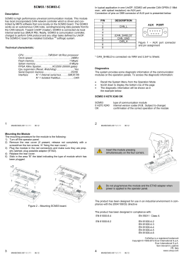
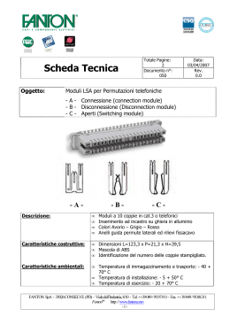
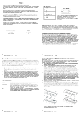
TCM17
Place ferrite as close as possible to the unit.
Description
The TCM17 communication module is an interface designed to connect the
operator panel to EIB.
The communication will be through the AUX port and the dedicated adapter
ETAD02. The technical data is listed in the table below:
Installing the adapter
1) Plug the 9 pins connector of ETAD02 with AUX port on the
rear side of the panel.
2) Fix the ETAD02 adapter to the panel with the two screws of
the 9 pins connector (type SUB-D).
Compatibility
The TCM17 module is compatible with all operator panels Series 400 and
with panels that have Firmware (FW) type: 32, 38, 52, 53, 54, 60, 70.
WIRE CONNECTIONS
Diagnostics
The system provides some diagnostic information on the operation of the
communication modules. To access the diagnostic information:
•
Recall the System Menu from the Operation Mode
•
Scroll down to display the bottom row of the page
The diagnostic information will be shown as in the example below:
TCM17 0 H000 X000 OK
TCM17
0 H000 X000
OK
type of communication module
internal version codes (N.B.: Subject to change)
confirmation of the correct operation of the module
Connect unshilded twisted pair wires on WAGO243-211 using the connection shown below.
1
MANTCM17-001 V.1.07
06.12
2
Mounting the Module
The mounting procedure for the module is the following:
1) Turn off the operator panel.
2) Remove the rear cover (if present, release not completely with a screwdriver the two screws “A” fixing the rear cover)..
3) Plug the module in the red connectors and make sure they are properly
latched, plug possible adaptor (ETAD).
4) Replace the rear cover.
5) Stick in the area “B” the label indicating the type of module which has
been plugged.
MANTCM17-001 V.1.07
06.12
Insert the module pressing
simultaneously on the four corners.
Do not plug/remove the module and the ETAD adapter when
power is applied to the operator panel.
The product has been designed for use in a residential, commercial and
light-industrial environments in compliance with the 2004/108/CE directive
The product has been designed in compliance with:
EN 61000-6-3
EN 55022 Class B
EN 61000-6-1
EN 61000-4-2
EN 61000-4-3
EN 61000-4-4
EN 61000-4-5
EN 61000-4-6
Figure 2 – Mounting AUX port module.
EN 50090-2-2
EN 60669-2-1
3
MANTCM17-001 V.1.07
06.12
4
Copyright © 2006-2012 Exor International S.p.A.
Exor International S.p.A.
San Giovanni Lupatoto VR, Italy
www.uniop.com
MANTCM17-001 V.1.07
06.12
TCM17
Descrizione
Posizionare la ferrite il più vicino possibile all’unità.
Il modulo di comunicazione TCM17 è una interfaccia realizzata per
permettere il collegamento di un pannello operatore ad una rete EIB.
La comunicazione avviene attraverso la porta AUX e l’adattatore dedicato
ETAD02. Le caratteristiche tecniche sono le seguenti:
Installazione interfaccia
1) Inserire il connettore SUB-D 9 poli della ETAD02 nel
connettore della porta AUX sul retro del pannello.
2) Fissare l’adattatore ETAD02 al pannello tramite le due viti del
connettore SUB-D.
Compatibilità
Il TCM17 è compatibile con tutti i pannelli interfaccia operatore Serie 400 ed
i pannelli dotati di firmware (FW) tipo: 32, 38, 52, 53, 54, 60, 70.
COLLEGAMENTI
Diagnostica
Il corretto inserimento e funzionamento del modulo può essere verificato
nella maniera seguente:
•
con pannello in Operation Mode attivare il menu System
•
effettuare lo “scroll” verso il basso fino all’ultima riga
il pannello mostrerà una riga diagnostica che avrà questa forma:
TCM17 0 H000 X000 OK
TCM17
0 H000 X000
OK
nome del modulo
codici interni di versione (N.B.: soggetto a variazione)
conferma inserimento corretto
Collegamento del connettore WAGO 243-211 alla rete.
1
MANTCM17-001 V.1.07
06.12
2
Montaggio
La procedura di montaggio dei moduli è la seguente:
1) Spegnere il pannello.
2) Rimuovere il coperchio (se presenti, svitare non completamente le due
viti “A” che fissano il coperchio dei connettori).
3) Inserire il modulo negli appositi connettori rossi ed assicurarsi che siano
correttamente agganciati, connettere eventuali adattatori (ETAD).
4) Rimontare il coperchio.
5) Applicare nello spazio “B” tratteggiato sul coperchio l’etichetta che
descrive le caratteristiche della porta AUX.
MANTCM17-001 V.1.07
06.12
Inserire il modulo premendo sui
quattro angoli contemporaneamente.
Non inserire/togliere il modulo (ed eventuali adattatori ETAD) a
macchina accesa.
Il prodotto è stato progettato per l’impiego in ambienti residenziali,
commerciali e dell’industria leggera in conformità alla direttiva 2004/108/CE
Il prodotto è stato progettato in conformità alle norme:
EN 61000-6-3
EN 55022 Class B
Figure 2 – Montaggio modulo porta AUX.
EN 61000-6-1
EN 61000-4-2
EN 61000-4-3
EN 61000-4-4
EN 61000-4-5
EN 61000-4-6
EN 50090-2-2
EN 60669-2-1
3
MANTCM17-001 V.1.07
06.12
4
Copyright © 2006-2012 Exor International S.p.A.
Exor International S.p.A.
San Giovanni Lupatoto VR, Italy
www.uniop.com
MANTCM17-001 V.1.07
06.12
Scaricare