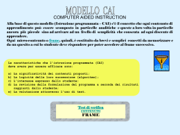
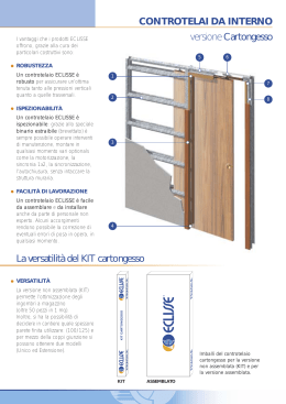
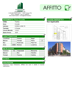
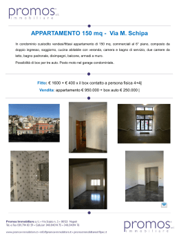
MONTAGGIO E POSA IN OPERA CONTROTELAIO
BOX FRAME ASSEMBLY AND SET UP
Controtelaio metallico
Metallic box‐frame
A
A
Guida di scorrimento
Sliding rail
B
B
D
Distanziale superiore
Upper distance transom
Montante di battuta
Upright
C
C
Distanziale inferiore di allineamento
Lower alignment transom
D
A. Inserire la guida di scorrimento nell'apposita sede del coperchio e spingerla fino a battuta. B. Fissare l'estremità della guida di scorrimento al montante di battuta con gli appositi chiodi. C. Inserire il distanziale superiore nell'apposita sede del Controtelaio e del montante di battuta. D. Inserire il distanziale di allineamento inferiore nell'apposita sede del Controtelaio e del montante di battuta.
A. Insert the sliding rail into the provided space of the cover and push it until it stops . B. Fix the sliding rail extremity to the upright with supplied nails. C. Insert the upper distance transom in the provided space of the box‐frame and of
the upright. D. Insert the lower alignment transom in the provided space of the box‐frame and of the upright.
POSA IN OPERA CONTROTELAIO
PLACEMENT OF BOX‐FRAME FOR PLASTERED WALL
SU PAVIMENTI ESISTENTI: Appoggiare il Controtelaio sul pavimento in linea con la parete da costruire. Verificando il piombo ed il piano, in caso di discordanza con il piombo dare la precedenza al piano. Aprire le zanche di muratura posta sul montante di battuta in legno e sul lato della cassa metallica del Controtelaio.
SU PAVIMENTI DA COSTRUIRE: Allineare il Controtelaio alla parete da costruire. Spessorarlo sotto affinché la base sia in linea con il piano finito del pavimento. Eseguire con scrupolo questa operazione perché se il Controtelaio venisse posato ad una altezza superiore al piano finito del pavimento, a porta montata la luce sotto risulterebbe eccessiva. Procedere quindi all'intonaco; la prima passata di circa un centimetro, appena asciugata dare una secondo mano a pareggio del telaio per poi rasare come uso locale.
ON EXISTENT FLOORS: Place the box‐frame on the floor, aligned with wall to be built. Check the alignment of plumb and ground, in case of discordance with plumb, give priority to the ground. Open masonry brackets placed on the wooden upright and on the metallic box‐frame side.
ON FLOORS TO BE BUILT: Align the box‐frame to the wall to be built. Add shims under the box in order having the base aligned with same level of finished floor. Carry out this step scrupulously because if the box frame is placed higher than the level of finished floor, after the door installation, the light below will be excessive. Then plaster: the first sheeting of one centimeter, as soon as it's dry, it is ready for the second sheeting until the same level of the frame and smooth in the traditional way.
POSA DEL CONTROTELAIO CARTONGESSO
PLACEMENT OF BOX‐FRAME FOR PLASTER‐BOARD
Appoggiare il Controtelaio sul pavimento in linea con la parete da costruire. Verificando il piombo ed il piano, in caso di discordanza con il piombo dare la precedenza al piano. Accostare al montante in legno un distanziale a U per cartongesso, fissarlo poi al pavimento ed al montante stesso. Eseguire la stessa operazione sul lato del cassonetto metallico fissando il distanziale al pavimento e sulla parte superiore del Controtelaio in corrispondenza
del traverso. Installare un ulteriore distanziale ad U sulla parte superiore del controtelaio. Fissare la lastra di cartongesso con viti auto filettanti assicurandosi che le viti coincidano con la parte cava del cassonetto. La lunghezza massima consentita per le viti sono di mm.20, considerando uno spessore lastra massimo di 12.5 mm.
Put the box‐frame on the floor aligned with the plaster‐board wall to be built. Check the alignment of plumb and ground, in case of discordance with plumb, give priority to the ground. Put the wooden upright near the distance transom with U form for plaster‐board, fix it to the ground and to the upright itself. Do the same in the metallic box‐frame side fixing the transom to the ground and to the corresponding box‐frame upper part. Place an additional transom with U form to the box‐frame upper part. Fix the plaster‐board sheet with self‐tapping screws making sure that screws correspond to the hollow part of the box‐frame. The maximum screws length can be 20mm, considering a maximum plaster‐board sheet thickness of 12,5mm. ANTE DOPPIE E KIT GIUNZIONE GUIDE
DOUBLE WING DOOR AND JOINING KIT
L2
L1
ANTA DOPPIA: Dopo aver inserito e fissato il traverso al Controtelaio, inserire la staffa di giunzione in una delle guide per circa metà della sua lunghezza e fissare con l'apposita vite. Inserire quindi
il secondo traverso e inserire la seconda guida fino in
battuta della prima. Fissare la seconda guida con l'apposita vite, inserire i distanziali nelle apposite sedi della maschera frontale del Controtelaio e procedere con le operazioni di posa.
DOUBLE WING: After inserting and fixing the transom to the box‐frame, insert the joining bracket into one rail for half of its length and fix it with supplied screws. Then insert the second transom and the second rail until they touch. Fix the second rail with supplied screws, insert distance transom into the provided space of the box‐frame frontal part, then go on with the box‐frame placement.
KIT DI GIUNZIONE: Qualora si voglia realizzare un Controtelaio anta doppia da due Controtelai anta unica, sezionare i listelli di pareggio intonaco di 45 mm. sulla parte posteriore della guida. Procedere all'inserimento dei distanziali inclusi nel kit di giunzione guide e procedere come al precedente punto.
JOINING KIT: If you want to obtain a box‐frame for a
double wing door from two single box‐frames, cut the profiles for plaster alignment of 45mm in the back part of the rail. Insert supplied distance transom are included in the kit, as it is specified on the step above.
sede interna
H1
H2
internal box frame space
INGOMBRI
L1= L nominale +40 mm.
L2= L nominalex2 +70 mm.
H1= H nominale
H2= H nominale + 85 mm.
SEDE INTERNA:
PARETI INTONACABILI:
parete finita mm. 90, sede interna mm.55
parete finita mm.105, sede interna mm.70
parete finita mm.125, sede interna mm.85
PARETI CARTONGESSO:
parete finita mm. 100, sede interna mm.55
parete finita mm.125, sede interna mm.70
OVERALL SIZES
L1= Nominal W +40 mm.
L2= Nominal Wx2 +70 mm.
H1= Nominal H
H2= Nominal H + 85 mm.
INTERNAL BOX FRAME SPACE:
PLASTERED WALLS:
Finished wall mm. 90, internal box frame space mm.55
Finished wall mm. 105, internal box frame space mm.70
Finished wall mm. 125, internal box frame space mm.85
PLASTER‐BOARD WALLS:
Finished wall mm. 100, internal box frame space mm.55
Finished wall mm. 125, internal box frame space mm.70
MONTAGGIO DEL PANNELLO
DOOR PANEL ASSEMBLY
mostrina di finitura
frame cover
nasello inferiore auto centrante
lower rail
traversi
superiore
upper transoms
montante
di battuta
impact upright
montante porta
spazzolino
profile brush holder
Togliere la maschera frontale e pulire accuratamente l'interno del cassonetto.
Posizionare la guida inferiore autocentrante alla base del cassonetto e fissarla o al Controtelaio metallico con gli appositi tasselli o a pavimento con tappi ad espansione. Inserire i montanti porta spazzolino sulla bocca del Controtelaio nelle apposite lamelle. Fissare le staffe di sospensione sulla parte superiore del pannello porta assicurandosi che le asole di introduzione carrello siano entrambe rivolte dallo stesso lato. Fissare i gommini sulla parte posteriore del pannello ed eventualmente spessorarli qualora si voglia far sporgere il pannello una volta aperto. Introdurre i carrelli nella guida di scorrimento dall'apposita asola posta sul lato del montante di battuta. Agganciare il pannello ai carrelli e regolarne l'altezza e il piombo rispetto al piano del pavimento. Inserire i traversi superiori e successivamente lo stipite di battuta controllandone la perpendicolarità rispetto al pannello posto in chiusura. Terminare fissando le mostrine di finitura su entrambi i lati del muro.
Remove the frontal cover and clean carefully the box‐frame interior part.
Place the lower rail in the box‐frame base and fix it to the metallic box with supplied dowels or to the floor with fishers. Insert door profiles brush holders into the box‐frame opening in the provided seat. Fix suspension brackets
to the upper part of the door panel and make sure that provided holes for the carriage introduction are turn to the same side. Fix impact rubber to the back door panel side and add shims if you prefer the door panel is not completely disappeared into the box‐frame when the door is open. Insert carriages into the sliding rail in the provided hole placed in the side of the impact upright. Hook the door panel to the sliding carriages, regulate the height and check the alignment of plumb respect to the ground level. Insert upper transoms and then the impact jamb checking their perpendicularity respect the closed door panel. At the end fix frame covers on both wall sides.
TABELLA MISURE / INGOMBRI DIMESION TABLE LARGHEZZA NOMINALE
NOMINAL WIDTH
CONTROTELAIO ANTA UNICA
BOX FRAME ONE WING
INGOMBRO TOTALE
OVERALL SIZE
PANNELLO
DOOR PANEL
L
H
L
H
L
H
600
2000
2100
2000
2100
2000
2100
2000
2100
2000
2100
2000
2100
2000
2100
1280
2085
2185
2085
2185
2085
2185
2085
2185
2085
2185
2085
2185
2085
2185
624
2005
2105
2005
2105
2005
2105
2005
2105
2005
2105
2005
2105
2005
2105
700
800
900
1000
1100
1200
1480
1680
1880
2080
2280
2480
724
824
924
1024
1124
1224
LARGHEZZA NOMINALE
NOMINAL WIDTH
H
L
H
L
H
1200
2000
2100
2000
2100
2000
2100
2000
2100
2000
2100
2000
2100
2000
2100
2470
2085
2185
2085
2185
2085
2185
2085
2185
2085
2185
2085
2185
2085
2185
624
2005
2105
2005
2105
2005
2105
2005
2105
2005
2105
2005
2105
2005
2105
1600
1800
2000
2200
2400
PANNELLO
DOOR PANEL
L
1400
CONTROTELAIO ANTA DOPPIA
BOX FRAME DOUBLE WING
INGOMBRO TOTALE
OVERALL SIZE
2870
3270
3670
4070
4470
4870
724
824
924
1024
1124
1224
ISTRUZIONI DI MONTAGGIO NASELLO AUTOCENTRANTE
SELF-CENTERING LOWER REGULATION PART ASSEMBLY CARD
CONTROTELAIO PER INTONACO 105mm E CARTONGESSO 125mm
BOX-FRAME FOR 105mm PLASTERED WALL AND 125mm PLASTER-BOARD WALL
Fig.1
’
A
T
VI
O
N EW
N
Per controtelai da spessore parete 105mm
intonacabile e 125mm cartongesso,il nasello
viene inserito all’interno della “bocca” del
controtelaio (Fig.1) e fissato a pavimento
mediante viti e tappi ad espansione (Fig.2)
Fig.2
In box-frames for 105mm plastered wall and
125mm plaster-board wall, the lower regulation
part is placed inside the box-frame opening (Fig.
1) and fixed to the floor thanks to screws and
fisher (Fig. 2)
CONTROTELAIO PER INTONACO 90mm
E CARTONGESSO 100mm
BOX-FRAME FOR 90mm PLASTERED WALL
AND 100mm PLASTER-BOARD WALL
CONTROTELAIO PER INTONACO SPESSORE
PARETE 125 e 145mm
BOX-FRAME FOR 125mm and 145mm
PLASTERED WALL
Fig.3
Fig.3
Fig.1
Fig.2
Fig.1
Fig.4
Fig.2
Fig.4
Per controtelai da spessore parete 90mm intonacabile e 100mm
cartongesso, il nasello prima di essere inserito all’interno della “bocca” del
controtelaio (Fig.3) e fissato a pavimento mediante viti e tappi ad
espansione (Fig.4), deve essere tagliato al primo riferimento più esterno
(Fig.1 e 2) da entrambi i lati.
In box-frames for 90mm plastered wall and 100mm plaster-board wall,
before inserting the lower regulation part in the box-frame opening (Fig. 3)
and fixing it to the floor with screws and fisher (Fig. 4), have to be cut
along the first outer sign (Fig. 1 and 2) in both sides.
Per controtelai da intonaco con spessore parete
differente dai due precedentemente descritti, il
nasello prima di essere fissato a pavimento
mediante viti e tappi ad espansione (Fig.3 e 4),
deve essere tagliato al secondo riferimento più
interno (Fig.1 e 2) da entrambi i lati.
In box-frames for walls with thickness different
from two previously described, before fixing the
lower regulation part to the floor with screws
and fisher (Fig. 3 and 4), it have to be cut along
the second inner sign (Fig. 1 and 2) in both
sides.
CONTROTELAIO CON POSA SOTTO LIVELLO DEL PAVIMENTO FINITO
BOX-FRAME WITH ASSEMBLY UNDER THE FINISHED FLOOR LEVEL
Fig.1
Livello Pavimento Finito
Finished floor level
A
Fig.2
Livello Pavimento Finito
Finished floor level
Livello Pavimento Finito
Finished floor level
B
Fig.4
Fig.3
MITO SRL - Via del Lavoro, sn - 61010 Tavullia (PU) - TEL. +39 0721 476320 - FAX +39 0721 476408 - www.mito.it - [email protected]
Scaricare