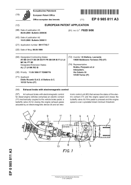
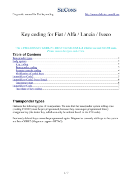
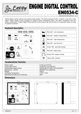
Fiat 127
3
1049 cm
opis části servisního manuálu
Fiat 127 Internet Fan Club (http://fiat127.okruhy.cz)
Fiat 127 - 1050
Supplement
Contents
Introduction ... ... ... ... ... ... ... ... ... ... ... ... ... ... ... ... ... ... ... ... ... ... 1
Specifications ... ... ... ... ... ... ... ... ... ... ... ... ... ... ... ... ... ... ... ... ... ... 2
Engine … … … ... ... ... ... ... ... ... ... ... ... ... ... ... ... ... ... ... ... ... ... ... 3
1049 cc engine - general
Crankshaft - refitting
Piston rings - refitting
Pistons and connecting rods - reassembly
Pistons - refitting
Connecting rods to crankshaft - reassembly
Oil pump - reassembly
Crankshaft oil seals and carriers - refitting
Sump - refitting
Auxiliary shaft and seal - refitting
Belt - pulleys and tensioner - refitting
Cylinder head and valve gear - reassembly
Distributor - refitting
Toothed drive belt - removal, refitting and adjusting
Valve clearances - adjustment
Engine - final assembly
Engine removal – 127 Special and 127 from chassis number 1104290 onwards
Fuel system ... ... ... ... ... ... ... ... ... ... ... ... ... ... ... ... ... ... ... ... ... ...
Carburettors - general
Weber or Solex single venturi carburettors
Weber dual venturi carburettor
Carburettor overhaul - general
4
Ignition system... ... ... ... ... ... ... ... ... ... ... ... ... ... ... ... ... ... ... ... ...
Automatic centrifugal advance curves
5
Braking system... ... ... ... ... ... ... ... ... ... ... ... ... ... ... ... ... ... ... ... ...
Brake fluid reservoir and vacuum servo unit (Sport)
6
Electrical system... ... ... ... ... ... ... ... ... ... ... ... ... ... ... ... ... ... ... ... . 7
Charging system
Fuses (127 Special)
Fuses (1049 cc models)
Bodywork and fittings ... ... ... ... ... ... ... ... ... ... ... ... ... ... ... ... ... ...
Model variations
Wing mouldings and front spoiler (Sport) - removal and refitting
Rear spoiler (Sport) – removal and refitting
2/34
8
Fiat 127 Internet Fan Club (http://fiat127.okruhy.cz)
Fiat 127 - 1050
1. Introduction
Since its first introduction in 1971 the FIAT
127 has undergone a continuing programme of
improvements concerned mainly with styling
and trim alterations. However, in 1977 a new
model range was introduced which included the
option of a larger engine of 1049 cc capacity
with a single overhead camshaft. In
appearance, cars in the new range are broadly
similar to the earlier models but they have a
lower bonnet line, larger glass area and
redesigned bumpers.
engine with a twin choke carburettor. Apart from
minor body styling changes, the Sport is
equipped with a larger capacity sump, twin
exhaust tailpipes, servo braking, additional
instrumentation and a laminated windscreen.
This supplement has been added to cater
for some of the production changes which have
been made, but principally to cover the 1049 cc
engine. The material given in Chapters 1 to 12
still applies unless superseded by information
contained in this Supplement. Therefore,
always read this Chapter in conjunction with the
rest of the book.
In October 1978, the FIAT 127-Sport was
launched. This is a high performance version of
the three door hatchback having the 1049 cc
3/34
Fiat 127 Internet Fan Club (http://fiat127.okruhy.cz)
Fiat 127 - 1050
2. Specifications
Capacities (1049 cc models)
Engine oil (including filter change)
L, C and CL ... ... ... ... ... ... ... ... …
Sport
... ... ... ... ... ... ... ... ...
5.5 pints (3.1 litres)
7.7 pints (4.4 litres)
Coolant
... ... ... ... ... ... ... ... …
9.7 pints (5.5 litres)
Fuel
... ... ... ... ... ... ... ... …
6.7 gallons (30.5 litres) including 6.2 pints
(3.5 litres) reserve
Transmission oil
... … ... ... ... ... ... ... .
4.2 pints (2.4 litres)
1049 cc OHC engine
General
Type number ... ... ... ... ... ... ... ... …
127 A 000 (C, L and CL);
127 A1.000 (Sport)
Bore
... ... ... ... ... ... ... ... …
2.992 in (76 mm)
Stroke
... ... ... ... ... ... ... ... ...
2.276 in (57.8 mm)
Capacity
... ... ... ... ... ... ... ... …
64 cu in (1049 cc)
Compression ratio
... ... ... ... ... …
9,3 : 1 (C, L and CL);
9,8 : 1 (Sport)
Maximum horsepower (DIN) ... ... ... ...
50 HP at 5600 rpm (C, L and CL);
70 HP at 5600 rpm (Sport)
Valve mechanism
Inlet :
Opens ... ... ... ... ... ... ... ... ...
Closes ... ... ... ... ... ... ... ... ...
Exhaust :
Opens ... ... ... ... ... ... ... ... ...
Closes ... ... ... ... ... ... ... … …
Valve clearances (cold) :
For checking valve timing:
Inlet ... ... ... ... ... ... ... ...
Exhaust ... ... ... ... ... ... ...
Adjustment for running (engine cold) :
Inlet ... ... ... ... ... ... ... ...
Exhaust ... ... ... ... ... ... ...
C, L and CL
Sport
2° BTDC
42°ABDC
6° BTDC
46°ABDC
42° BBDC
2° ATDC
47° BBDC
7° ATDC
0.028 in (0.70 mm)
0.028 in (0.70 mm)
0.032 in (0.80 mm)
0.032 in (0.80 mm)
0.012 in (0.30 mm)
0.016 in (0 40 mm)
0.016 in (0.40 mm)
0.020 in (0.50 mm)
Cylinder block and connecting rods
inches
mm
Cylinder bore diameter *
2.992 to 2.994
76.00 to 76.05
* Cylinder bores are graded and have a variation of 0.0004 inch (0.01 mm) between each grade
Main bearing housing bore diameter
2.044 to 2.045
51.921 to 51.934
1.088 to 1.091
27.64 to 27.70
Width of centre main bearing cap between
thrust washers
Connecting rod big-end diameter
1.85 to 1.8560
47.130 to 47.142
Connecting rod small-end diameter
0.8638 to 0.8646
21.94 to 21.96
Big-end bearing shell thickness
0.0606 to 0.8646
1.539 to 1.55
4/34
Fiat 127 Internet Fan Club (http://fiat127.okruhy.cz)
Fiat 127 - 1050
Big-end bearing shell undersize range
0.01; 0.02; 0.03; 0.04 0.254; 0,508; 0.762; 1.016
Gudgeon pin interference fit in small-end:
C, L and CL
0.0004 to 0.0017
0.01 to 0.042
Sport
0.0004 to 0.0006
0.01 to 0.016
Crankpin to bearing fit clearance
0.0009 to 0.003
0.022 to 0.076
Maximum misalignment between big and small-end axes measured 4.92 in (125 mm) from
Connecting rod
± 0.004
± 0.10
Pistons, rings and pins
inches
mm
Standard piston diameter, measured 0.925 inch (23.5 mm) from piston skirt base :
Grade A
2.989 to 2.9894
75.92 to 75.93
Grade C
2.9898 to 2.9902
75.94 to 75.95
Grade E
2.9906 to 2.9909
75.96 to 75.97
Range of oversize pistons
0.0079; 0.0157; 0.0236
0.2; 0.4; 0.6
Piston boss diameter (C, L and CL):
Grade 1
0.8654 to 0.8656
21.982 to 21.986
Grade 2
0.8655 to 0.8657
21.986 to 21.990
Grade 3
0.8657 to 0.8659
21.990 to 21.994
Piston boss diameter (Sport):
Grade 1
0.7874 to 0.7875
19.999 to 20.002
Grade 2
0.7875 to 0.7876
20.002 to 20.005
Ring groove width (C,L and CL) :
Top groove
0.0604 to 0.0612
1.535 to 1.555
Centre grove
0.0799 to 0.0807
2.030 to 2.050
Bottom groove
0.1562 to 0.1570
3.967 to 3.987
Ring groove width (Sport) :
Top groove
0.0604 to 0.0612
1.535 to 1.555
Centre grove
0.0793 to 0.0801
2.015 to 2.035
Bottom groove
0.1558 to 0.1566
3.957 to 3.977
Standard gudgeon pin diameter (C, L and CL):
Grade 1
0.8650 to 0.8651
21.970 to 21.974
Grade 2
0.8651 to 0.8652
21.974 to 21.978
Grade 3
0.8652 to 0.8654
21.978 to 21.982
Standard dudgeon pin diameter (Sport) :
Grade 1
0.7872 to 0.7873
19.994 to 19.997
Grade 2
0.7873 to 0.7874
19 997 to 20.000
Oversize gudgeon pin diameter
0.0079; 0.0157; 0.0236
0.2; 0.4; 0.6
Piston ring thickness :
Top compression ring
0.0582 to 0.0587
1.478 to 1.490
2nd oil control ring
0.0779 to 0.0783
1.978 to 1.990
3rd oil scraper ring
0.1545 to 0.1550
3.925 to 3.937
Piston to bore fit clearance
0.0028 to 0.0035
0.070 to 0.090
Gudgeon pin fit clearance in piston
0.0003 to 0.0006
0.008 to 0.016
Piston ring side clearance in groove:
1st compression ring
0.0018 to 0.003
0.045 to 0.077
2nd oil control ring
0.0010 to 0.0022
0.025 to 0.057
3rd oil scraper ring
0.0008 to 0.002
0.020 to 0.052
Piston ring end gap:
1st compression ring (C, L and CL)
0.0079 to 0.0157
0.20 to 0.40
1st compression ring (Sport)
0.0118 to 0.0197
0.30 to 0.50
2nd oil control ring
0.0118 to 0.0197
0.30 to 0.50
3rd oil scraper ring
0.0079 to 0.0138
0.20 to 0.35
0.2; 0.4; 0.6
Piston rings oversize range
0.0079; 0.0157; 0.0236
5/34
Fiat 127 Internet Fan Club (http://fiat127.okruhy.cz)
Crankshaft
Main bearing journal diameter
Standard main bearing shell thickness
Main bearing shell undersize range
Standard crankpin diameter
Main bearing journal fit clearance
Width of centre main bearing cap between
thrust washers
Standard thrust washers thickness
Thrust washers oversize range
Crankshaft endfloat
Maximum misalignment of main bearing
journals
Maximum misalignment of main bearing
journals to crankpins
Maximum ovality of crankpins and main
bearing journals after grinding
Maximum taper of crankpins and main
bearing journals after grinding
Maximum run-out of crankshaft flange with
dial gauge stylus 31 mm (1.22 ins) from
crankshaft rotational axis
Maximum run-out between flywheel face
and crankshaft flange, and between
flywheel face and crankshaft axis
Cylinder head
Standard valve guide housing bore
Standard valve outside diameter
Oversize valve guide
Valve guide interference fit
Fitted valve guide internal diameter
Valve stem diameter
Valve stem fit clearance in guide
Valve head diameter:
Inlet (C, L and CL)
Inlet (Sport)
Exhaust
Valve seat width
Valve seat internal diameter:
Inlet (C, L and CL)
Inlet (Sport)
Exhaust (C, L and CL)
Inlet (Sport)
Angle of valve seat
Angle of valve face
Valve springs:
Inner spring part no.
Outer spring part no.
Valve gear
Camshaft journal diameter:
Valve gear end
Centre
Flywheel end
Fiat 127 - 1050
inches
1.8972 to 1.898
0.0721 to 0.0726
0.01; 0.02; 0.03; 0.04
1.7318 to 1.7326
0.0009 to 0.033
1.2785 to 1.2805
mm
48.189 to 48.209
1.831 to 1.845
0.254; 0.508; 0.762; 1.016
43.988 to 44.008
0.022 to 0.083
32.475 to 32.525
0.0909 to 0.0929
0.0959 to 0.0979
0.0022 to 0.0104
0.0012
2.31 to 2.36
2.437 to 2.487
0.055 to 0.265
0.030
0.0138
0.350
0.0002
0.005
0.0002
0.005
0.001
0.025
0.0039
0.10
inches
0.5886 to 0.5896
0.5921 to 0.5928
0.002; 0.0039; 0.0098
0.0025 to 0.0043
0.3158 to 0.3165
0.3139 to 0.3146
0.0012 to 0.0026
mm
14.950 to 14.977
15.040 to 15.058
0.05; 0.10; 0.25
0.063 to 0.108
8.022 to 8.040
7.974 to 7.992
0.030 to 0.066
1.3327 to 1.3445
1.4311 to 1.4429
1.1358 to 1.1476
0.0787 to 0.0866
33.85 to 34.15
36.35 to 36.65
28.85 to 29.15
2.0 to 2.2
1.1063 to 1.1142
1.2244 to 1.2323
0.9882 to 0.9961
1.0276 to 1.0354
45° ± 5'
45° 30' ± 5'
28.1 to 28.3
31.1 to 31.3
25.1 to 25.3
26.1 to 26.3
4134900
4170458
inches
mm
1.1789 to 1.1795
1.0630 to 1.0636
0.9843 to 0.9848
29.945 to 29.960
27.000 to 27.015
25.000 to 25.015
6/34
Fiat 127 Internet Fan Club (http://fiat127.okruhy.cz)
Camshaft bearing bore diameter in head:
Valve gear end
Centre
Flywheel end
Camshaft journals fit clearance
Cam lift (C, L and CL)
Cam lift (Sport):
Inlet
Exhaust
Standard tappet bore diameter
Standard tappet outside diameter
Tappet fit clearance
Shim thickness
Auxiliary shaft
Diameter of bush bores in crankcase:
Front
Rear
Fitted bush internal diameter:
Front
Rear
Diameter of shaft journals:
Front
Rear
Bush fit
Shaft/bush fit clearance (front and rear)
Lubrication system
Oil pump
Pump drive
Oil pressure relief valve
Pump rotors endfloat
Outer rotor to body clearance
Inner to outer rotor clearance
Oil pressure at 212°F (100°C)
Fiat 127 - 1050
1.1807 to 1.1817
1.0648 to 1.0657
0.9860 to 0.9870
0.0012 to 0.0028
0.3425
0.3622
0.3642
1.4567 to 1.4577
1.4557 to 1.4565
0.0002 to 0.0020
0.1279; 0.1299; then
0.0039 steps to 0.1850
29.990 to 30.015
27.045 to 27.070
25.045 to 25.070
0.030 to 0.070
8.700
9.200
9.250
37.000 to 37.025
36.975 to 36.995
0.005 to 0.050
3.2b; 3.30; then
0.10 steps to 4.70
inches
mm
1.6339 to 1.6350
1.5733 to 1.5745
41.500 to 41.530
39.962 to 39.992
1.5143 to 1.5151
1.4553 to 1.4561
38.464 to 38.484
36.964 to 36.984
1.5115 to 1.5125
38.393 to 38.418
1.4525 to 1.4535
36.893 to 36.918
There must always be an interference fit
0.0018 to 0.0036
0.046 to 0.091
Four lobe rotor type
Through auxiliary shaft
Incorporated in pump
0.0018 to 0.0047
0.0006 to 0.0022
0.0010 to 0.0039
50 to 70 Ibf/in2
0.045 to 0.120
0.016 to 0.055
0.025 to 0.100
(3.5 to 5 kgf/cm2)
Cooling system
Radiator fan thermal switch
Cuts in .
Cuts out
194° to 201°F (90° to 94°C)
185° to 192°F (85° to 89°C)
Engine coolant thermostat
Starts to open
Fully open
176° to 183°F (80° to 84°C)
205°F (96°C)
Impellor vanes to pump body fit clearance
0.0315 to 0.0512 in (0.8 to 1.3 mm)
Radiator cap relief pressure
11.4 Ibf/in2 (0.8 kgf/cm2)
Fuel system
Weber 32 ICEV 16/150 carburettor (C, L and CL models)
Venturi diameter
0.8465 in (21.5 mm)
Main jet .
0.0453 in (1.15 mm)
7/34
Fiat 127 Internet Fan Club (http://fiat127.okruhy.cz)
Air correction jet
Slow running jet
Emulsion tube type
Accelerator pump jet
Needle valve seat
Accelerator pump output (10 strokes)
Cold starting device
Float level
CO level
Fiat 127 - 1050
0.0728 in (1.85 mm)
0.0177 in (0.45 mm)
F74
0.0157 in (0.40 mm)
0.0591 in (1.50 mm)
2 to 3 cm3
Automatic choke
1.4016 to 1.4213 in (35.6 to 36.1 mm)
2.5%
Solex C32 TDI/4 carburettor (C, L and CL models)
Venturi diameter
0.8465 in (21.5 mm)
Main jet
0.0453 in (1.15 mm)
Air correction jet
0.0768 in (1.95 mm)
Slow running jet
0.0177 in (0.45 mm)
Emulsion tube type
71
Accelerator pump jet
0.0177 in (0.45 mm)
Needle valve seat
0.0630 in (1.60 mm)
Accelerator pump output I10 strokes)
3 to 5 cm3
Cold starting device
Automatic choke
Float level
0.8661 to 0.9449 in (22.0 to 24.0 mm)
CO level
2.5%
Weber 34 DMTR 47/250 carburettor (Sport models)
Primary venturi
Secondary venturi
Venturi diameter
0.8661 in (22.0 mm)
0.9449 in (24.0 mm)
Main jet
0.0421 in (1.07 mm)
0.0500 in (1.27 mm)
Air correction jet
0.0728 in (1.85 mm)
0.0866 in (2.20 mm)
Slow running jet
0.0177 in (0.45 mm)
0.0276 in (0.70 mm)
Slow running air bleed
0.0413 in (1.05 mm)
0.0276 in (0.70 mm)
Accelerator pump jet
0.0157 in (0.40 mm)
--Needle valve seat
0.0689 in (1.75 mm)
Accelerator pump output (10 strokes)
8.55 cm3
Cold starting device
Manually operated strangler choke
Float level
0.2657 to 0.2854 in (6.75 to 7.25 mm)
Fuel pump
Output
Actuating lever stroke (C, L and CL)
Actuating lever stroke (Sport)
Delivery pressure at 4000 engine rpm
and fuel temp 30°C (86°F)
75 litres/hr (16.5 gal/hr)
2.4 to 2.6 mm (0.0949 to 0.1024 in)
2.4 to 2.9 mm (0.0949 to 0.1142 in)
0.17 kgf/cm2 (2.55 Ibf/in2)
lgnition system
Distributor
Type and code
Automatic centrifugal advance
Condenser capacity (50 to 1000 Hz)
Magneti Marelli S155HX
25° ± 2° at 4500 rpm
0.20 to 0.25 µF
Clutch
Lining outer diameter
181.5 mm (7.146 in)
Lining inner diameter
127.0 mm (5.0 in)
8/34
Fiat 127 Internet Fan Club (http://fiat127.okruhy.cz)
Maximum run-out of driven plate linings
Fiat 127 - 1050
0.2 mm (0.008 in)
Travel of release flange, corresponding
to a pressure plate displacement of not less
than 0.067 in ~1.7 mm)
8.5 mm (0.3346 in)
Transmission
Synchromesh
1st and 2nd, Borg-Warner baulk ring type,
3rd and 4th, Porsche spring ring type
Gear ratios
First
Second
Third
Fourth
Reverse
3.910 : 1
2.055 : 1
1.348 : 1
0.963 : 1
3.615 : 1
Final drive ratio (C,L and CL)
4.071 : 1 (14/57)
Final drive ratio (Sport)
4.462 : 1 (13/58)
Overall ratios
Gears
1st
2nd
3rd
4th
Reverse
C, L and CL
Sport
15.92
17.45
8.7
9.17
5.49
6.01
3.92
4.30
14.72
16.13
Electrical system
Alternator
Type (C, L and CL)
Type (Sport)
Maximum output (approx)
Maximum current (approx)
Direction of rotation (drive end)
Engine/alternator drive ratio
Magneti Marelli AA 108-14V-33A
Lucas 18ACR-A4V-45A
570 watts
40 amps (C, L and CL)
50 amps (Sport)
1050 to 1150 rpm (C, L and CL)
1100 to 1200 rpm (Sport)
3.4 to 3.8 ohms (C, L and CL)
3.18 to 3.22 ohms (Sport)
Clockwise
1.8 : 1
Alternator regulator (C, L and CL models)
Type
Alternator speed for adjustment
Current for thermal balance
Regulating voltage
Magneti Marelli RTT 110 AB
6000 rpm
20 amps
14.2 +0.3–0.2 volts
Cut-in speed at 12V and 20°C (68°F)
Field winding resistance across slip rings at 20°C (68°F)
9/34
Fiat 127 Internet Fan Club (http://fiat127.okruhy.cz)
Lamps
Headlamps (C, L and CL)
Headlamps (Sport)
Brake and rear light
Turn indicators
Reversing lights
Parking lights
Number plate
Courtesy light
Boot light
Turn repeaters
Cigar lighter light
Instrument panel
Ignition warning
Turn indicator warning
Headlamp warning
Coolant temperature warning (L models)
Oil pressure warning
Fuel warning
Hazard warning
Sidelamp (out) warning (Sport only)
Brake warning (Sport only)
Heated rear window warning (Sport only)
Fiat 127 - 1050
40/45 watts
55/60 watts (Halogen)
5/21 watts
21 watts
21 watts
5 watts
5 watts
5 watts
5 watts
4 watts
4 watts
3 watts
3 watts
1.2 watts
1.2 watts
1.2 watts
1.2 watts
1.2 watts
1.2 watts
3 watts
1.2 watts
1.2 watts
Fuses
For fuse details (127 Special, L, C, CL and Sport) see Sections 23 or 24
Steering and suspension (Sport only)
Steering angles
Inner wheel
Outer wheel
Front wheel alignment (toe setting)
Laden
Unladen
Roadwheels
Size
Tyres
34° 50’
32° 10’
0.079 in (2.0 mm) toe-in to 0.079 in (2.0 mm) toe-out
0.138 in (3.5 mm) to 0.217 in (5.5 mm) toe-in
4½ B x 13
135 SR-13 or 155/70 SR-13
All 1049 cc models
Main bearing cap bolts
Engine mounting securing bolts
Cylinder head to block bolts and nuts:
1 st stage
2nd stage
Final stage
Manifold to head nuts
Connecting rod big-end nuts
Flywheel to crankshaft bolts
Driven gear (Plastic) to camshaft retaining bolt
Driven gear (steel) to camshaft retaining bolt
Camshaft cap nuts
10/34
Ibf ft
59
43
kgf m
8.2
6
30
45
61
20
38
61
87
87
14
4.1
6.2
8.5
2.8
5.2
8.5
12
12
2
Fiat 127 Internet Fan Club (http://fiat127.okruhy.cz)
Ignition distributor clamp nut
Oil pump to crankcase bolts
Cylinder head outlet pipe bolt
Water pump/alternator drive pulley nut
Alternator bracket to crankcase bolt
Alternator to lower bracket bolt
Cylinder head upper bracket bolt
Alternator to upper bracket nut
Upper bracket securing bolt
Oil pressure switch
Coolant temperature switch
Spark plug
Sport models only
Engine
Flexible mounting to body (engine side)
Flexible mounting support (engine side to body)
Flexible mounting upper support to gearbox
Engine crossmember to body
Flexible mounting support nut (gearbox side)
Flexible mounting support bolt to body
(gearbox LH side)
Steering and suspension
Steering wheel retaining nut
Front wheel bearing ring nut
Front wheel hub nut
Roadwheel bolts
Front suspension track control arm to body
Front suspension balljoint to hub carrier
Rear wheel hub nut
Transmission
Starter motor bolt to bellhousing lower support
Gear selector shaft nut
Upper gear lever relay lever
Idler support securing nut
Differential case flange to gearbox housing
11/34
Fiat 127 - 1050
11
13
16
101
20
36
20
36
13
24
36
27
1.5
1.8
2.2
14
2.8
5
2.8
5
1.8
3.3
5
3.8
65
18
18
18
18
65
9.0
2.5
2.5
2.5
2.5
9.0
22
44
160
64
20
40
160
3.0
6.0
22.0
8.8
2.7
5.5
22
18
18
22
18
18
2.5
2.5
3.0
2.5
2.5
Fiat 127 Internet Fan Club (http://fiat127.okruhy.cz)
Fiat 127 - 1050
3. Engine
1049 cc engine - general
1 This engine is of overhead camshaft design,
using shims for valve clearance adjustment. The
crankshaft is supported in five main bearings,
the centre one incorporating the thrust washers
which control crankshaft endfloat.
2 An auxiliary shaft, driven by the toothed
camshaft belt, is used to drive the distributor and
the fuel pump. 3 Most major engine components
can be removed while the engine is in the car,
but operations on the crankshaft, main bearings
and flywheel can only be carried out after the
engine has been removed.
4 Engine removal and subsequent dismantling
follows closely the information given for the
overhead valve engine in Chapter 1, but the
following sequence for complete engine
dismantling is recommended:
(a) Engine ancillaries (alternator, fuel pump,
distributor)
(b) Timing belt cover
(c) Water pump
(d) Timing belt tensioner and belt
(e) Manifolds
(f) Cylinder head complete with camshaft
(g) Crankshaft pulley
(h) Auxiliary shaft sprocket
(i) Sump
(j) Oil pump and auxiliary shaft
(k) Connecting rods and pistons
(l) Flywheel and crankshaft oil seal carriers
(m) Crankshaft and main bearings
3.7A Thoroughly clean the bearing shells and seats before
assembly
5 If the cylinder head is to be dismantled, before
withdrawing the camshaft, have a suitably divided
container ready so that the valve clearance
adjusting shims can be extracted and kept in strict
originally installed order together with their
appropriate valves, springs etc.
6 All engine parts must be thoroughly cleaned
and examined as explained in Chapter 1. Where
required, all defective parts should be renewed
before reassembly starts.
Crankshaft – refitting
7 Fit the main bearing shells to their seats in the
crankcase after making sure that both shells and
seats are spotlessly clean and dry (photos).
8 With a light smear of grease, fit the two half
thrust washers each side of the centre bearing
with the oil grooves in each washer facing away
from the bearing shell (photo).
9 Using clean engine oil lubricate the bearing
shells and crankshaft main bearing journals
(photo).
10 Carefully lower the crankshaft into its bearings
in the crankcase after making sure that it is the
right way round. Spin the shaft to distribute the oil
(photo).
11 Fit the clean and dry bearing shells to the main
bearing caps. Oil the bearing face and fit the
bearing caps to the crankcase. Make sure that
each cap is fitted to its own location by checking
the groove marks in the base, and that each cap
is the right way round. This is achieved when the
axial locating tags in each half bearing shell butt
on the same side (photos).
3.7B Note that central bearing shell has no oil groove but all
shell are axially located by an offset tag
12/34
Fiat 127 Internet Fan Club (http://fiat127.okruhy.cz)
13.1. 1049 cc engine, longitudinal section (Sec.3)
13/34
Fiat 127 - 1050
Fiat 127 Internet Fan Club (http://fiat127.okruhy.cz)
13.2. 1049 cc engine, cross section (Sec.3)
(The engine is installed inclined 6°rearwards)
14/34
Fiat 127 - 1050
Fiat 127 Internet Fan Club (http://fiat127.okruhy.cz)
Fiat 127 - 1050
12 Refit the main bearing cap bolts and screw
them up fingertight. Spin the crankshaft and, if
all is well, tighten the bolts to the specified
torque load and turn the crankshaft again to
check freedom of rotation (photo).
13 Measure the crankshaft endfloat with feeler
gauges. If this exceeds the specified tolerance,
oversize thrust washers will have to be fitted.
Pision rings - refitting
14 Follow the procedure given in Chapter 1,
Section 42.
Pistons and connecting rods–reassembly
3.8 The half thrust washers are fitted each side of the
centre bearing
15 Follow the procedure given in Chapter 1,
Section 43 (photo).
Pistons – refitting
16 Follow the procedure given in Chapter 1,
Section 44.
17 Note that the connecting rods in the 1049 cc
engine have two oil jet holes leading from the
big-end bearing (photo).
18 When the piston is correctly fitted it will have
the valve depressions adjacent to the side of the
block with the cylinder head studs in (photo).
3.9 Oil the bearings and crankshaft journals…
Connecting rods to crankshaftreassembly
19 Follow the procedure given in Chapter 1,
Section 45.
20 Torque load the big-end cap nuts to the
reading quoted in the Specifications of this
Chapter 13 - it is different from the value quoted
for the 903 cc engine (photo).
Oil pump - reassembly
3.10 … and then fit the crankshaft into the crankcase
21 The oil pump fitted to the 1049 cc engine is a
Hobourn-Eaton rotor type of pump which is quite
different from the gear pump fitted to the 903 cc
engine. It consists of a four lobed rotor rotating
in a five slotted outer rotor which is mounted
eccentrically to the inner rotor. As the inner rotor
rotates the outer rotor is driven round, and the
spaces between the lobes on the inner rotor and
the slots in the outer rotor increase and
decrease once per revolution. The increasing
spaces are connected to the pump inlet and
cause oil to be drawn into the pump. The
decreasing spaces connect with the pump outlet
through which the oil is forced to feed the
engine. A springloaded relief valve in the outlet
of the pump vents excessive oil pressure into
the sump. The efficiency of the pump depends
15/34
Fiat 127 Internet Fan Club (http://fiat127.okruhy.cz)
Fiat 127 - 1050
3.11A Fit the bearing shell ti the main bearing caps…
3.11B …and then fit caps to the crankcase after oiling the
shells
3.11C Ensure that each cap is the right way round in its
own location with the one with four marks at the flywheel
end of the crankcase
3.12 Tighten main bearing cap bolts with a torque wrench
3.15 Piston and connecting rod assembly
3.17 One of the oil jet holes in the big-end – the other is on
the other side of the rod
16/34
Fiat 127 Internet Fan Club (http://fiat127.okruhy.cz)
Fiat 127 - 1050
3.18 The valve depressions in the piston are adjecent to
the cylinder head studs in the block
3.20 Torque tighten the big-end cap nuts
3.22A Firts fit outer rotor to the oil pump body…
3.22B …followed by the inner rotor
3.23 Measure the end clearance of the rotors with the
pump face
3.24 Measure the outer rotor to body clearance…
17/34
Fiat 127 Internet Fan Club (http://fiat127.okruhy.cz)
Fiat 127 - 1050
3.25 …and the inner to outer rotor clearance
3.27A Fit the oil pump pressure relief valve plunger and
spring…
3.27B …followed by the retainer plate and circlip
3.28 Refit the pump lower half body
3.29 Fit the oil pump to the crankcase
3.30 The oil tube is secured by a bracket to the centre main
bearing cap with a bolt and washer
18/34
Fiat 127 Internet Fan Club (http://fiat127.okruhy.cz)
Fiat 127 - 1050
3.32 Fitting the crankshaft seal and carrier at flywheel
and…
3.33 …and at the timing cover end
3.34 The timing indicator bracket is located behind the two
top bolts of the seal carrier
3.36 Fit the sump to the crankcase
on fine clearances and these should be checked
during assembly.
22 Fit the outer rotor to the pump body and then
fit the inner rotor (photos).
23 Lay an accurate straight edge across the
faces of the rotors and pump body and measure
the clearance with feeler gauges (photo).
24 Insert a feeler gauge between the outer rotor
and the pump body to measure the clearance
(photo).
25 Similarly insert a feeler gauge between the
inner rotor lobe tip and the outer rotor to
measure the clearance between the two (photo).
26 Compare the clearances with the tolerances
quoted in the Specifications to this Chapter. Any
excessive clearance could result in low oil
pressure, and as the inner and outer rotors are
matched pairs the only solution is a new or
reconditioned pump assembly.
27 Fit the oil pressure relief valve plunger to the
pump body followed in turn by the spring,
retainer plate and circlip (photos).
28 Lubricate the rotors with clean engine oil and
refit the pump lower half body and strainer
(photo).
29 With a new gasket, fit the assembled oil
pump to the crankcase block and secure with
the two long bolts (photo). Tighten to the
specified torque load.
30 Fit the oil tube to the crankcase securing it by
its bracket to the centre main bearing cap with
its retaining bolt. Tighten to the specified torque
load (photo).
Craknshaft oil seals and carriers-refitting
31 Clean the flywheel mounting spigot on the
end of the crankshaft and lubricate the
crankshaft seal with clean engine oil. Fit a new
gasket.
19/34
Fiat 127 Internet Fan Club (http://fiat127.okruhy.cz)
Fiat 127 - 1050
3.39 Fitting the auxiliary shaft…
3.40 …and its seal and carrier
3.42 This face of the pulley fits towards the shaft
3.43 Fit the belt tensioner bracket a new gasket to the
block …
3.44 …followed by the spring-loaded plunger…
3.45 …and then the tensioning wheel
20/34
Fiat 127 Internet Fan Club (http://fiat127.okruhy.cz)
Fiat 127 - 1050
3.46 The bevelled washer is fitted bevel outwards and is
followed by…
3.47 …the crankshaft toothed pulley
3.48A Valve guide oil seal
3.48B Inserting a valve followed by…
3.48C …the lower spring seat and springs…
3.48D …and upper spring seat
21/34
Fiat 127 Internet Fan Club (http://fiat127.okruhy.cz)
Fiat 127 - 1050
3.48E A magnet is useful for refitting the split collets
3.48F After assembly a sharp tap on the valve stem will
help to bed the parts in
3.49A Use a small pointed tool to …
3.49B …prise out the vlave clearance adjusting shim
3.49C This shim is 4,15mm thick
3.49D Refit each tappet bucket with its shim to its vlave
22/34
Fiat 127 Internet Fan Club (http://fiat127.okruhy.cz)
32 Carefully ease the lip of the seal onto the
spigot and secure the carrier with the bolts and
washers (photo).
33 Similarly clean the crankshaft at the timing
belt end and fit the seal and carrier. Retain by
the two bottom bolts (photo). 34 Put the timing
indicator bracket over the two top bolt holes in
the seal carrier and fit the two top bolts (photo).
Sump - refitting
35 Make sure that there are no remnants of the
old gasket on the sump flange and fit a new
gasket using a little grease to hold it in position.
Check that it is bedded down evenly all round
the flange.
36 Fit the sump to the crankcase. Put the load
spreading washers on each bolt and screw into
the crankcase (photo).
37 Tighten the bolts evenly to avoid warping the
flange.
Auxiliary shaft and seal - refitting
38 Clean the auxiliary shaft bearings and
lubricate with clean engine oil.
39 Insert the shaft into the crankcase bushes
and rotate the shaft to spread the oil (photo).
40 Lubricate the auxiliary shaft seal in its carrier
and carefully ease the seal over the shaft spigot
(photo).
41 Fit the seal carrier retaining bolts and
washers and tighten.
Belt pulleys and tensioner - refitting
42 Fit the toothed pulley to the auxiliary shaft.
The recess in the pulley fits on the auxiliary shaft
with the dowel on the shaft in the hole in the
pulley (photo). Fit the retaining bolt and washer
and partially tighten, as it will be necessary to
wait until the drivebelt has been fitted before
finally tightening this bolt. Alternatively, it is
possible to hold the auxiliary shaft carefully in a
vice, fit the seal and carrier to the shaft, followed
by the toothed pulley and its retaining bolt and
washer, and then tighten the bolt fully before
fitting the complete assembly to the block.
43 The belt tensioner bracket can now be fitted.
Clean off all traces of old gasket from the
bracket and block and use a new gasket on
assembly. Fit the retaining bolts and washers
and tighten (photo).
44 Insert the spring-loaded plunger assembly
into the tensioner bracket (photo).
45 The tensioning wheel in its carrier can now
be fitted. Put the top bolt and washer in first and
then bear down to compress the spring and fit
Fiat 127 - 1050
the bottom bolt through the kidney-shaped slot.
Note that this latter bolt has an additional, large
washer against the wheel carrier. Temporarily
tighten the two bolts they will have to be
retightened after the belt has been fitted (photo).
46 If the key had previously been removed from
the pulley end of the crankshaft, clean the key
slot and refit the key. Then slide on the bevelled
washer, making sure that the bevel is on the
side away from the crankcase (photo).
47 Refit the crankshaft toothed pulley (photo).
Then the V-belt pulley can be refitted together
with its retaining nut and washer. Final
tightening of this nut can wait until the flywheel
has been fitted, when a 'gag' can be fitted to the
flywheel to hold the crankshaft whilst tightening
the nut - see Chapter 1, photo 23.2A.
Cylinder head and valve gear-reassembly
48 It is assumed that the valves will have
already been examined and renovated as
described in Chapter 1, Section 31. Follow the
procedure given in Chapter 1, Section 51 to
reassemble the valves, but note that new oil
seals should be fitted to this engine when the
valves have been inserted in the guides and
before the springs are fitted (photos).
49 Each tappet bucket contains a shim in the
head which is used to control the valve
clearance. Before assembling the buckets to
their valves, prise out each shim and take a note
of the thickness. This is etched on the lower face
of the shim and indicates the thickness in
millimetres to two decimal places. If the number
has worn off, use a micrometer to check the
shim thickness. Make a table showing each
valve by number and the thickness of shim on
assembly. Reassemble each shim to its bucket
and after lubricating with clean engine oil fit the
buckets to their respective valves (photos).
50 Lubricate the two camshaft bearings in the
cylinder head and carefully thread the camshaft
through the driving end hole and lower it onto its
bearings. The cams will rest on the tappet
buckets and the camshaft should now be turned
so that the two cams over No. 1 cylinder (driving
end) are pointing upwards (compression/firing
stroke). This is to reduce the bending load on
the camshaft as the two bearing halves are
being tightened down (photo).
51 Lubricate the camshaft bearing halves and fit
them to their respective studs in the head. Put
the steel bridge plates in position and fit the
washers and nuts (photo).
52 Tighten the four nuts a little at a time
23/34
Fiat 127 Internet Fan Club (http://fiat127.okruhy.cz)
progressively until the bearing halves meet.
53 Oil the camshaft seal and carefully fit it with
its carrier and a new gasket to the cylinder head
(photo).
54 Position the drivebelt guard backplate over
the camshaft seal carrier and fit the three bolts
and washers (photo). 55 Tighten the three bolts
retaining the backplate and seal carrier. Torque
load the four camshaft bearing securing nuts to
the specified setting.
56 Fit the camshaft toothed driving pulley with its
bolt and washer. Leave the final tightening until
the drivebelt is fitted (photo).
57 Check the valve clearances; the camshaft
can be turned by a spanner on the pulley
retaining bolt. Readjust any clearance if
necessary, as described later in this Section.
58 Owing to the small clearance between a
piston at TDC and the open valves during
exhaust/inlet overlap, it is imperative to get the
crankshaft and camshaft in their correct related
positions before turning the engine after fitting
the cylinder head. If this relationship is out then
serious damage could be done to the valves or
pistons by turning the crankshaft, as the pistons
will impinge on the valve heads. To avoid this
the following sequence should be observed. Set
the crankshaft as described in paragraph 59,
and the camshaft (before assembling the
cylinder head to the block) also as described in
paragraph 59. Fit the head to the block taking
care not to disturb the set positions and, finally,
fit the toothed drivebelt. Then the crankshaft can
be turned with no likelihood of damage.
Fiat 127 - 1050
59 Set the crankshaft by using a spanner on the
pulley retaining nut and aligning the mark on the
pulley with the long pointer on the timing
indicator bracket. Then set the camshaft by
aligning the hole in the camshaft pulley with the
cast ridge on the top of the camshaft seal carrier
just behind the toothed pulley (photo).
60 Fit a new cylinder head gasket with the word
ALTO upwards (photo). Do not use grease or
any other jointing compound. 61 Taking care not
to disturb the crankshaft or camshaft lower the
cylinder head onto the block (photo).
62 Fit the thick washers to the studs on the
manifold side of the block followed by the nuts.
Fit the bolts with their thick washers to the other
side of the block and screw the bolts and nuts
down to lightly compress the gasket. The bolts
and nuts must now be torque loaded by stages
(see Specifications) in sequence, to the
specified load and in the order shown in
Fig.13.3. This may present some difficulty as,
owing to the shape of the cylinder head, it is not
possible to get a socket spanner fitted to a
torque wrench over the cylinder head nuts.
These can be tightened using a ring or openended spanner as an extension to the torque
wrench, but then, of course, the applied torque
will be different to the torque registered or set on
the torque wrench. To overcome this a simple
calculation can be made so that a setting can be
established for the torque wrench which, with an
extension, will produce the specified torque
loading. This value varies with the ratio of the
Fig. 13.3. 1049 cc engine cylinder head nut and bolt tightening sequence (Sec.3)
24/34
Fiat 127 Internet Fan Club (http://fiat127.okruhy.cz)
Fiat 127 - 1050
3.50 Position the camshaft in the cylinder head …
3.51 …and fit the half bearings and bridge plates
3.53 Fit the camshaft seal in its carrier to the cylinder head.
3.54 …followed by the drive belt quard backplate
3.56 Fit the camshaft toothed pulley
3.59 Hole in pulley aligned with část ridge, view from
behind the wheel
25/34
Fiat 127 Internet Fan Club (http://fiat127.okruhy.cz)
Fiat 127 - 1050
extension length and the torque wrench length
and is calculated by using the formula:
where A is the specified torque loading (Ibf ft or
kgf m), B is the torque to be set, or read, when
using an extension (Ibf ft or kgf m), y is the
length of extension (ft or m), and z is the length
of torque wrench (ft or m).
Example: Specified torque is 60 Ibf ft, length of
extension is 6 in, and length of torque wrench is
2 ft, then B = (60 x 2) = (6/12 + 2) = 120 =2'/z =
48 Ibf ft; torque wrench setting or indication.
When measuring, use centres of bolts/nuts and
centre of torque wrench drive square. When
calculating, keep values constant, that is, don't
mix inches and feet for example (photos). 63 Fit
the drivebelt as described later in this Section.
When fitted, the auxiliary shaft pulley bolt and
the camshaft pulley bolt can be torque loaded to
the specified settings if these were not done on
assembly.
3.68 Fitting the distributor
Distributor - refitting
64 The distributor is mounted nearly vertical on
the oil filter side of the engine and is driven by
skew gears from the auxiliary shaft. In turn the
distributor shaft also drives the oil pump through
a splined coupling (photo).
65 It is more convenient to set the contact
breaker gap before fitting the distributor to the
engine. Adjust to the specified clearance
(photo).
66 Turn the crankshaft in the normal direction of
rotation until the line on the crankshaft pulley is
adjacent to the first of the three pointers on the
timing bracket. This is 100 BTDC, the second
pointer is 50 BTDC and the large, third pointer is
TDC. Note which cylinder, either 1 or 4, is on the
compression stroke. This is indicated by both of
the inlet and exhaust cams pointing upwards
causing their relative valves to be shut. 67
Rotate the distributor shaft until the rotor is
opposite the terminal in the distributor cap
serving the same cylinder number as the one
which was on compression stroke and with the
contact breaker points just breaking.
68 Lubricate the distributor skew gear with clean
engine oil and insert the distributor into the
engine block. Watch the rotor carefully to see
how much it turns as the skew gears mesh.
Then withdraw the distributor, reset the rotor and
then preset it the same amount that it turned
3.70 Distributor clamp bolt
3.77 Fitting the toothed drivebelt-crankshaft V-belt pulley
removed for clarity
26/34
Fiat 127 Internet Fan Club (http://fiat127.okruhy.cz)
Fiat 127 - 1050
3.60 The cylinder head gasket is fitted ALTO upwards
3.61 Lower the cylinder head onto the block
3.62A Tighten the cylinder head bolts and nuts to the
specified torque
3.62B These cylinder head nuts might be difficult to torque
tighten
3.64 Distributor driveshaft skew gear
3.65 Checking the contact breaker gap
27/34
Fiat 127 Internet Fan Club (http://fiat127.okruhy.cz)
Fiat 127 - 1050
when initially inserted; then reinsert it into the
engine. Ideally the contact points should be just
breaking with the rotor opposite the correct
numbered terminal in the cap. If this is not the
case, repeat on a trial and error basis until this is
achieved (photo).
69 Fit the clamp washer and nut and lightly
tighten temporarily.
70 With a lamp and battery across the contact
breaker points and the clamp nut just loosened,
move the distributor body round its axis until the
light just goes out. Tighten the clamp nut to the
specified torque load (photo).
3.78 Setting the belt tensioner
3.84 Checking a valve clearance
3.87 Made-up tool for depressing tappet buckets
Toothed drivebelt - removal, refitting and
adjusting
Note: If adjustment is necessary on an old belt
or if the belt is removed for any reason, always
change the belt for a new one, never adjust
using the old belt.
71 The toothed drivebelt should be renewed at
36 000 miles (60 000 km). This can be done with
the engine in the car. 72 Using a spanner on the
crankshaft pulley nut turn the engine over until
the timing mark on the crankshaft pulley is
aligned with the TDC pointer (long one).
73 Remove the drivebelt cover and the
alternator/water pump drivebelt.
74 Check that the camshaft pulley timing hole is
aligned with the cast ridge on the seal housing;
refer to paragraph 59 of this Section. If it isn't,
turn the engine over one revolution to get it lined
up.
75 Before removing the drivebelt it must be
remembered that neither the camshaft nor the
crankshaft must be moved with the belt off, If
this precaution is not observed the pistons and
valves could impact causing serious damage.
76 Release the tension on the drivebelt by
slackening the bolt in the kidney-shaped slot on
the tensioner bracket, loosening
the other
(pivot) bolt, pushing the tensioner wheel against
the spring unit and tightening both bolts. Slide
the drivebelt off the pulleys.
77 Fit the new belt. Start at the crankshaft drive
pulley and, taking care not to kink or strain the
belt, ease it into place over the auxiliary shaft
pulley and the camshaft pulley. It might be
necessary to slightly turn the camshaft to get the
belt to mesh. This should always be done in the
direction of least movement to achieve a mesh,
Fit the belt on the tensioner pulley last. If this is
difficult do not lever or force the belt on but
recheck it and try again (photo).
28/34
Fiat 127 Internet Fan Club (http://fiat127.okruhy.cz)
78 Slacken the tensioner bolts to tension the belt
and retighten the bolts (photo).
79 Turn the engine over for two complete
revolutions to even out belt tension. Then again
slacken the tensioner bolts to let the tensioner
take up any slack and retighten the bolts. Never
turn the engine backwards or rock the camshaft
when tensioning the belt, as slack could develop
in the belt and it might jump a tooth.
80 Refit and tension the alternator/water pump
V-belt. Refit the drivebelt cover.
Valve clearances - adjustment
81 Checking the valve clearances should be
done at the 6000 miles servicing, or whenever
the cylinder head has been removed and
refitted for any reason. It is important that the
clearances are set correctly, otherwise the
timing will be wrong and the
engine
performance will be poor. If there is no
clearance at all, the valves and seats will soon
get burnt. Set the clearances with the engine
cold.
82 Remove the camshaft cover. The engine can
be turned over by either using a spanner on the
crankshaft pulley nut, or by jacking up a front
wheel, engaging top gear and using the wheel
to turn the engine.
83 Each tappet must be checked when its
operating cam is pointing upwards, 1800 away
from the tappet. Check the clearances in the
firing order, No. 1 cylinder first and then 3, 4
and 2. Do the exhaust of one cylinder and the
inlet of the one after, at the same time to
minimise the amount of engine turning. Counting
from the timing belt end, exhaust valves are
1-4-5-8, inlet valves 2-3-6-7.
84 Insert the feeler gauge for the appropriate
valve. See the
Specifications for correct
settings. The feeler should slide in readily
between cam and shim, but with slight frictional
drag. Try one a size thicker and one a size
thinner. The thick one should not go in and the
thinner one should be too loose (photo).
85 If the clearance is wrong, measure the
clearance and write it down with the number of
the valve. When all the clearances have been
checked, it will be necessary to remove those
shims which are fitted where the clearances are
wrong, and renew them with different thickness
shims. If a clearance is too big, use a thicker
shim. If a clearance is too small use a thinner
shim. Calculate by simple subtraction.
Fiat 127 - 1050
86 To change a shim, turn the engine until the
relevant cam is pointing upwards, then turn the
tappet in its housing so that the slot in the rim is
accessible.
87 The manufacturer provides special tools for
depressing tappets (Nos. A60480 and A60443).
These make the job easier if they can be
borrowed, but it is possible to do the job without
them. The best way is to make up a tool from a
piece of steel plate shaped as shown in the
photograph. Alternatively use a screwdriver to
lever the tappet down and another one, on edge,
to hold the tappet down by positioning it
between the camshaft and the rim of the tappet;
then remove the lever. This is quite tricky and
needs some care to avoid any damage. If in any
doubt about doing this job it should be left to a
FIAT agent. As well as having the right tools he
will also have a stock of shims from which to
choose those required to correct wrong
clearances. It is expensive buying shims that are
not required (photo).
88 With the tappet held down, prise the shim out
with a thin screwdriver. The FIAT way is to lift
the shim using compressed air, which is
effective if an air line is available. The shims are
held in quite strongly by the oil film and they
must be lifted up square or they will jam.
Remove the shim with long-nosed pliers
(photos).
89 When new, shims have their thickness
marked in millimetres on their undersides. This
marking may wear off and then it will be
necessary to measure their thickness with a
micrometer. From the thickness of the shim and
the error in the clearance, calculate the size of
shim required to produce the correct clearance.
90 Insert the new shim, numbered side down
towards the tappet. Remove the tools used for
depressing the tappet and repeat the operation
until all clearances are correct.
91 Using clean engine oil lubricate all moving
and sliding parts in the camshaft/tappet
assembly. Fit a new gasket and refit the
camshaft cover together with the nine bolts and
washers. Tighten the bolts progressively (photo).
Engine - final assembly
92 Completing assembly of the 1049 cc engine
follows broadly the procedure for that of the
smaller engine which is dealt with in Chapter 1,
Section 56.
93 The manifold gasket is supplied in two parts
for the 1049 cc engine (photo). These serve
29/34
Fiat 127 Internet Fan Club (http://fiat127.okruhy.cz)
Fiat 127 - 1050
3.88A With the tappet depressed…
3.88B …the shim can be removed
3.91 Fit the camshaft cover with a new gasket
3.93A The two-pieces gasket for manifold joint…
3.93B …and the manifolds fitted
4.1 Weber 32 ICEV carburettor
30/34
Fiat 127 Internet Fan Club (http://fiat127.okruhy.cz)
Fiat 127 - 1050
Fig. 13.4 Engine mounting (right-hand side) (Sec.3)
Fig. 13.5. Engine mounting (left-hand side) (Sec.3)
1 – Mounting
2 – Crankcase
1 – Mounting to chassis bolts
2 – Mounting
3 – Mounting to transmission bracket
both the inlet and exhaust manifolds which are
on the same side of the engine.
Engine removal - 127 Special and 127
from chassis number 1104290 onwards
94 The removal of the engine assembly from
these models is slightly different from that
described in Chapter 1, owing to redesigned
engine mountings.
95 For the later type of mountings,
disconnection of the engine is achieved by
removal of the engine suspension mounting
securing bolts after taking the weight of the
assembly on a hoist.
96 On refitting the assembly tighten the securing
bolts to the specified torque load.
4. Fuel system
Carburettors - general
1 On L, C and CL models the 1049 cc engine is
fitted with either a Weber 32 ICEV 161150 or a
Solex C32 TDI/4 carburettor with a downdraught
single venturi and automatic coolant heated
choke (photos).
2 On Sport versions, a dual venturi Weber
carburettor is fitted with manual choke.
Weber
or
carburettors
Solex
single
Removal and refitting
3 Remove the air cleaner
4 Disconnect the throttle cable (photo).
venturi
5 Disconnect the distributor vacuum pipe
(photo). 6 Disconnect the fuel flow and return
hoses
7 Disconnect the coolant hoses from the
automatic choke housing and tie the pipes as
high as possible to prevent coolant loss (photo).
8 Unbolt the carburettor flange mounting bolts
and lift the carburettor from the manifold.
9 Refitting is a reversal of removal, but use a
new flange mounting gasket
Dismantling and adjustment
10 Clean the outside of the carburettor, remove
the top cover screws and lift off the cover.
11 Clean out the float bowl.
12 Any jets or bleed screws if removed, should
only be cleaned by blowing air through them.
Never probe with wire or their calibration will be
ruined.
13 Check the float level by holding the
carburettor cover vertically so that the float
hangs down, and then measure between the
casting flange and the nearest point of the float.
Adjust if necessary by bending the float arm tab
until the clearance conforms with the
Specifications according to carburettor.
14 The automatic choke will not normally require
dismantling, but if the cover is removed, make
sure that the centre index marks on the cover
and housing are in alignment before tightening
the choke cover screws.
15 On later carburettors, the mixture screw is
fitted with a tamperproof cap and adjustment to
the slow-running should therefore be limited to
31/34
Fiat 127 Internet Fan Club (http://fiat127.okruhy.cz)
altering the throttle speed screw.
16 On earlier carburettors, or if new components
have been fitted to carburettors having a
tamperproof screw, then the slow-running and
mixture can be altered, but only if an exhaust
gas analyser is available in the case of later
carburettors, after the tamperproof cap has been
broken off.
17 On earlier units, use a device such as a
mixture adjustment aid or a vacuum gauge fitted
in accordance with the manufacturers'
instructions to obtain the correct slow-running
adjustment.
18 On later units, an exhaust gas analyser,
again used in accordance with the maker's
instructions, will ensure that the CO level is
within the limits specified. Fit a new tamperproof
cap on completion.
Fiat 127 - 1050
Weber dual venturi carburettor
Removal and refitting
19 These operations are similar to the
operations described in paragraphs 3 to 9 of this
Section, but the unit is of manually operated
choke design and will therefore not have coolant
hose attachments. A choke cable is fitted
instead.
Dismantling and adjustment
20 The operations are similar to those described
for the single venturi type carburettor, once the
upper body has been removed (six screws).
21 If jets are extracted, identify them as to which
side of the carburettor (primary or secondary)
they came from.
4.4 Throttle cable connection to Weber single venturi
carburettor
4.5 Weber single venturi carburettor installed (vacuum pipe
arrowed
4.7 Weber single venturi carburettor showing coolant hoses
(arrowed) to automatic choke housing. Note fuel hoses
connected to top right of carburettor
7.6 Location of fuse block - 1049 cc engine models
32/34
Fiat 127 Internet Fan Club (http://fiat127.okruhy.cz)
22 To check the float setting, hold the
carburettor cover vertically with the float hanging
down. The distance 'a' (see Fig. 13.8) measured
between the float and the cover (with gasket
fitted) should be 7 mm ± 0.25 mm. Where
necessary, bend the float tongue.
23 This type of carburettor is fitted with a
tamperproof cap on the mixture screw, and
unless an exhaust gas analyser is available,
restrict any adjustment to the slow-running to
turning the throttle speed screw.
Fiat 127 - 1050
is an economical proposition if the original one
has seen service to a high mileage. Very often a
generous allowance is made for the old unit.
Carburettor overhaul – general
24 Whenever it is decided to overhaul a
carburettor, always obtain the appropriate repair
kit in advance. If throttle or choke valve plates or
their spindles are worn, do not dismantle them
but obtain a new carburettor. A new carburettor
Fig. 13.7. Weber dual venturi carburettor flost setting
diagram (Sec.4)
Fig. 13.6. Solex carburetor adjustment screw (Sec.4)
A – Throttle speed screw B – Sealed mixture screw
1 – Carburettor top cover 7 – Float arm tab
2 – Fuel inlet needle valve 8 – Float arm
3 – Float stop
9 – Float
4 – Needle
10 – Gasket
5 – Return hook
a = 7 ± 0,25 mm
6 – Ball
Fig. 13.8. Weber dual venturi carburettor (Sec.4)
1 – Throttle cable
2 – Cable conduit
3 – Choke cable
4 – Throttle speed screw
5 – Throttle control diaphragm
Fig. 13.9. Location of mixture control screw (1) (Weber dual
venturi carburettor) (Sec.4)
33/34
Fiat 127 Internet Fan Club (http://fiat127.okruhy.cz)
…….. nedokončeno
34/34
Fiat 127 - 1050
Scaricare