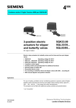
4 Electronic actuators for valves 554 SQX32... SQX82... SQX62... with 20 mm stroke • SQX32...: AC 230 V operating voltage, 3-position signal • SQX82...: AC 24 V operating voltage, 3-position signal • SQX62...: AC 24 V operating voltage, DC 0…10 V and/ or 0...1000 Ω or DC 4...20 mA positioning signals • Functional enhancement by means of auxiliary switch and potentiometer • Positioning force 700 N • Stroke 20 mm • For direct valve mounting without additional setting tasks • With manual adjustment and position indication • SQX82...U and SQX62U are UL approved Use To actuate two-port and three-port valves of type series VVF..., VVG..., VPF..., VXF..., and VXG... with 20 mm stroke • Field of use as per IEC 721-3-3 Class 3K5 • Ambient temperatures: − 15 ... + 50 °C • Medium temperature inside the valve: − 25 ... + 140 °C, > 140 °C: use SKB... actuators, < 0 °C: ASZ6.5 stem heating element required Functions SQX32..., SQX82... 3-position signal The reversible synchronous motor is controlled by a 3-position signal either via terminals Y1 or Y2 and generates the desired stroke by means of a blocking-proof gear train and a gear rack. valve stem retracts, through-port opens • Voltage on Y1: valve stem extends, through-port closes • Voltage on Y2: • No voltage on either Y1 or Y2: valve stem remains in the respective position SQX62, SQX62U Positioning signals: DC 0...10 V and / or 0...1000 Ω or DC 4...20 mA The SQX62... is either controlled via terminals Y and/or R. The recorded positioning signals control the synchronous motor by means of microprocessor electronics. This motor generates the desired stroke via a blocking-proof gear train and gear rack. valve stem retracts, through-port opens • Positioning signal Y, R increasing: • Positioning signal Y, R decreasing: valve stem extends, through-port closes • Positioning signal Y, R constant: valve stem remains in the respective position Siemens Building Technologies Landis & Staefa Division CM1N4554E / 07.1999 1/8 Selection of flow characteristic Via a slider (on the circuit board below the housing cover), the flow characteristics for the VVF..., VVG..., VXF..., VXG..., and VPF... valves can be changed from "equal percentage" to "linear". The microprocessor electronics are factory set to generate equal-percentage flow characteristics (log) related to the valve's throughport. Flow characteristics Relationship between the DC 0...10 V or DC 4...20 mA positioning signal and the volumetric flow: Y, R Actuator V H H g lin V100 U lo lin g Feedback signal lo Valve H 4554D02E U Y V V0 Y, R 0 4 0 10 V 20 mA 1000 Ω H V Calibration stroke Y = DC 0 ... 10 V V R = DC 4 ... 20 mA or 0...1000 Ω V100 = Volumetric flow 100 % U = DC 0 ... 10 V or DC 4 ... 20 mA V0 H = Stroke (valve) = = Air volume Volumetric flow 0 % log = Equal-percentage valve characteristic lin = Linear valve characteristic In order to determine the stroke positions 0 % and 100 % in the valve, calibration is required on initial commissioning. Prerequisites for calibration are mechanical coupling of the actuator SQX62 or SQX62U with a VV... or VX... valve as well as AC 24 V supply. Pressing button S3 − this button is available only if the housing cover has been removed − starts calibration. Calibration automatically performs the following steps: – Actuator moves to "0 stroke" position (valve closed), green LED flashes – Actuator moves to "100 stroke" position (valve open), green LED flashes – The measured values are saved in the microprocessor. The actuator then moves to the position as indicated by control signals Y or R; the green LED is lit permanently (normal operation). – Output U is inactive during calibration, i.e., the values correspond to the actual positions only after the green LED is lit permanently. Voltage at output U is limited to DC 9.7 ± 0.2 V. Current at output U is limited to 20 mA ± 0.5 mA. The calibration stroke can be repeated any number of times. Type summary Stellantriebe CM1N4554E / 07.1999 2/8 Standard version: Type Operating voltage SQX32.00 SQX32.03 SQX82.00 SQX82.03 SQX62 AC 230 V Control type (positioning signal) 3-position (floating) AC 24 V DC 0...10 V and / or 0...1000 Ω or DC 4...20 mA Runtime [s] Open Close 150 150 35 35 150 150 35 35 35 35 Siemens Building Technologies Landis & Staefa Division Special, UL approved version: SQX82.00U SQX82.03U SQX62U 3-position (floating) AC 24 V Accessories DC 0...10 V and / or 0...1000 Ω or DC 4...20 mA Type Auxiliary switch Auxiliary switch with potentiometer 1000 Ω Auxiliary switch pa i r Stem heating AC 24 V *) 150 35 35 Mounting location *) For actuators ASC9.5 ASZ7.4 ASC9.4 ASZ6.5 150 35 35 1x ASC9.5 or 1x ASZ7.4 or 1x ASC9.4 SQX32..., SQX82..., SQX82...U SQX32...,SQX82...,SQX62, SQX82...U, SQX62U 1x ASZ6.5 *) Only 1 accessory can be built into the actuator at a time. Exception: ASZ6.5 stem heating which is integrated between the actuator and the valve. Ordering and delivery On ordering, indicate the actuator type and, where required, the accessory type; for example: SQX32.00 Actuator, valve and accessories are packed and delivered separately and are not mounted on delivery. Equipment combinations The SQX... electronic actuators allow for actuating two-port and three-port valves of type series VVF..., VVG..., VPF..., VXF..., and VXG... with 20 mm stroke: Type DN [mm] PN [bar] Data sheet Two-port valves VV... (control or safety shutoff valves)e) VVF21... (Flange) 4310 25...80 6 VVF31... (Flange) 4320 25...80 10 VVF41... (Flange) 4340 50 16 VVG41... (Thread) 4363 15...50 16 VVF52... (Flange) 4373 15...40 25 Three-port valves VX... (control valves for "mixing" and "diverting" functions) VXF21... (Flange) 4410 25...80 6 VXF31... (Flange) 4420 25...80 10 VXG41... (Thread) 4463 15...50 16 VXF41... (Flange) 4440 15...50 16 Combination valve VP... (two-port valve with integrated diff. pressure controller) VPF52... (Flange) 4374 15...40 25 See the associated valve data sheets for permissible differential and close-off pressures ∆pmax and ∆ps. Mechanical design Actuators Siemens Building Technologies Landis & Staefa Division • • • • • • • • • • Maintenance-free, electronic actuator Actuators SQX32..., SQX82... with reversible synchronous motor Actuators SQX62... with synchronous motor, controlled by microprocessor electronics Blocking-proof gear train with self-lubricating porous bearings Force-sensing end switches to protect components from overload Selectable flow characteristic: Equal percentage (log) or linear (lin) Manual adjustment with automatic reset to control mode Slot for auxiliary switch and potentiometer in SQX32..., SQX82... Stem heating between valve and actuator SQX32..., SQX82..., SQX62... The actuators SQX82...U and SQX62U are UL approved CM1N4554E / 07.1999 3/8 SQX32..., SQX82..., SQX62...: 1 0 1 2 0 0 1 3 1 1 2 3 4 4554Z01 4 4554Z03 SQX62: 4554Z02 SQX32..., SQX82...: Manual adjustment Coupling to valve stem Position indication (0 to 1) Console 5 5 6 7 S3 12 Y2 U M R Y G G0 11 6 Y1 7 5 6 7 Mounting space for auxiliary switch or auxiliary switch pair or auxiliary switch and potentiometer Terminal strip Bonding screw (for SQX32...) 8 9 LIN 1000 Ω 5 6 7 8 9 Button S3 "Manual calibration" Microprocessor LED, red/ green (operating status iindication) Terminal strip DIL switches No. 1: «log» / «lin» *) No. 2: «4-20mA» / «1000Ω» *) *) bold print = Factory setting Auxiliary switch ASC9.5 Auxiliary switch pair ASC9.4.4 4554Z04 4554Z06 Accessories 4-20mA LOG 12 ON N Adjustable switching points Auxiliary switch with potentiometer ASZ7.4: Stem heating ASZ6.5: 4554Z07 4554Z05 Adjustable switching point Adjustable switching point for media below 0 °C. Mounting between valve and actuator See section "Technical data" for more information. Disposal CM1N4554E / 07.1999 4/8 The various material types used require that you disassemble the unit and sort the components prior to disposal. Siemens Building Technologies Landis & Staefa Division Engineering notes Conduct the electric connections in accordance with local regulations on electric installations as well as the unit or connecting diagrams on pages 7 and 8. Observe all safety-related requirements and restrictions to prevent injuries and damages to goods. The ASZ6.5 stem heating has a heating output of 30 VA and must keep the valve stem from freezing when used in a cooling range of 0 °C ... − 25 °C. For this case, do not insulate the actuator console and the valve stem, as air circulation must be ensured. Do not touch the hot parts without prior protective measures to avoid burns. Non-observance of the above may result in accidents and fires ! Additionally, pay attention to permissible temperatures as listed in sections "Use" and "Technical data". If an auxiliary switch is required, indicate its switching point on the plant schematic. Mounting notes 4554Z08 Mounting positions Permitted Permitted Permitted Not permitted The valve mounting instructions are printed on the rear of the actuator. Accessory instructions are located in the respective accessory's packaging. During commissioning, check the wiring and conduct a functional check. Additionally, check or make the required settings at the auxiliary pair or the auxiliary switch. 0 0 0 1 1 1 1 Coupling fully retracted 4554Z10 0 4554Z09 Commissioning notes Coupling fully extended If the manual adjustment know is turned clockwise to the end position, the Landis & Staefa valves of type series VVF..., VVG..., VPF..., VXF..., and VXG... are closed (stroke = 0 %). On pending controller signals, the actuator always moves to the preselected position as soon as the manual adjustment button is released. For SQX62 and SQX62U only Siemens Building Technologies Landis & Staefa Division • The factory setting for the flow characteristic is "equal percentage = log". • Calibration stroke – On initial connection of the actuator to AC 24 V, trigger the calibration stroke by pressing button S3 (see "Functions"). A special note for initial positioning stroke has been glued to the housing cover. – Repeat the calibration stroke when mounting on a new valve a previously calibrated actuator. – The calibration stroke can be repeated any number of times. CM1N4554E / 07.1999 5/8 Maintenance notes For actuator service work: • Turn off the pump and the operating voltage, close the shutoff valves, depressurize the pipes and allow them to cool down. Disconnect the electrical connections from the terminals, where required. • Recommission the actuator only after mounting on a VV... or VX... valve and, for SQX62… actuators, after recalibration. Warranty The technical data (∆pmax, ∆ps, leakage rate, noise level and life) apply only when used together with the Landis & Staefa valves as listed in "Equipment combinations". Use with third-party valves expressly voids any warranty claims. Technical data Actuators Power supply Function dat Operating voltage SQX32... SQX82..., SQX82...U SQX62, SQX62U Frequency Power consumption SQX32.00, SQX82.00U SQX32.03, SQX82.00, SQX82.03, SQX82.03U SQX62, SQX62U 3 VA 6,5 VA 8 VA Switching capacity of the limit switches SQX32... SQX82..., SQX82...U on terminals 11 or 12 AC 250 V, 6 A res., 2.5 A ind. AC 24 V, 5 A res., 0.75 A ind. Control type (positioning signal) SQX32..., SQX82..., SQX82...U SQX62, SQX62U Runtime SQX32.00, SQX82.00, SQX82.00U SQX32.03, SQX82.03, SQX82.03U SQX62, SQX62U Positioning force Stroke Signal inputs SQX62, SQX62U Terminal Y*) Voltage Current Terminal R *) Current max. impedance Resistance *) Signal outputs SQX62, SQX62U AC 230 V ± 15 % AC 24 V ± 2 0 % AC 24 V ± 2 0 % 50 oder 60 Hz 3-position DC 0...10 V and / or 0...1000 Ω or DC 4...20 mA (proportional) at 50 Hz at 60 Hz 150 s 120 s 35 s 30 s 35 s 30 s 700 N 20 mm DC 0 ... 10 V (corresponds to 0 ... 100 % stroke) max. 0.1 mA / 5 nF DC 4…10 V (corresponding to 0…100 % stroke) 250 Ω / 5 nF 0...1000 Ω (corresponds to 0 ... 100 % stroke) If a DC 4…20 mA control signal is switched to terminal R, terminal Y cannot be used simultaneously! Terminal U **) Voltage Current DC 0 ... 10 V corresponds to 0 … 20 mm stroke DC 4 ... 20 mA corresp. to 0 … 20 mm stroke **) The measuring signal at terminal U corresponds to the stroke position, i.e., at measuring signal DC 0 ... 10 V, the result from a max. selection of the DC 0...10 V control signal at input Y and of the 0...1000 Ω control signal at input R is processed; for the DC 4...20 mA measuring signal, the DC 4...20 mA control signal at input R is processed. Housing protection Environmental conditions CM1N4554E / 07.1999 6/8 Housing protection Cable entry glands SQX32..., SQX82..., SQX62 SQX82...U, SQX62U IP 54 EN 60529 Pg 11 (3x) for standard 1/2" conduit connector (2x) or Pg 16 Medium temperature, maximum permissible temp. inside valve 140 °C Operation Climatic conditions Temperature Humidity IEC 721-3-3 Class 3K5 − 15 ... + 50 °C 5...95 % r.h. Siemens Building Technologies Landis & Staefa Division Standards Transport Climatic conditions Temperature Humidity IEC 721-3-22 Class 2K3 − 30 ... + 65 °C < 95 % r.h. Storage Climatic conditions Temperature Humidity IEC 721-3-1 Class 1K3 − 1 5 ... + 50 °C 5...95 % r.h.. conformity as per EMC directive low voltage directive UL conformity declaration 89/ 336/ EEC 73 / 23 / EEC UL 873 Materials Actuator housing and console Housing box and manual adjustment knob Die-cast aluminium Plastic Dimensions Actuators see "Dimensions" Weight Actuators Weight without packaging With packaging 1.5 kg 1.7 kg Accessories AC 250 V, 10 A res., 3 A ind. Auxiliary switch ASC9.5 fo SQX32..., SQX82..., SQX82...U Switching capacity Auxiliary pair ASC9.4 for SQX32..., SQX82..., SQX82...U Switching output of one auxiliary switch Auxiliary switch and potentiometer ASZ7.4 (as one unit) for SQX32..., SQX82..., SQX82...U Switching output of auxiliary switch Change of overall resistance of the potentiometer at nominal stroke 20 mm 0...1000 Ω (corresponds to 0 ... 100 % stroke) Stem heating ASZ6.5 for SQX32..., SQX82..., SQX82...U, SQX62, SQX62U Operating voltage Power consumption AC 24 V 30 W Diagrams SQX32.00, SQX32.03 SQX82.00, SQX82.03, SQX82.00U, SQX82.03U AC 230 V, 3-position AC 24 V, 3-position Y2 3 6 c b a 100% 0% ∼ 11 N Cm1 Cm2 c1 c1 c2 c1 1000 Ω Y2 1000Ω Cm2 12 4 c1 c2 5 7 8 3 6 c b a 100% 0% M Cm1 Y1 100% 100% 0% 0% End switch End switch Auxiliary switch ASC9.5 Auxiliary switch Pair ASC9.4 Auxiliary switch and potentiometer (1000 Ω) ASZ7.4 Cm1 11 ∼M G 1000Ω Cm2 12 4 c1 c2 5 7 8 4554G02 Y1 4554G01 Internal diagrams Poss. mounting loc. for SQX32..., SQX82..., SQX82...U: 1 Auxiliary switch ASC9.5 or 1 Auxiliary pair ASC9.4 or 1 Auxiliary switch and potentiometer (as one unit) ASZ7.4 and 1 Additional ASZ6.5 stem heating SQX62, SQX62U G G0 Siemens Building Technologies Landis & Staefa Division Y R M U 4554G03 AC 24 V, DC 0...10 V and / or 0...1000 Ω or DC 4...20 mA G, G0 AC 24 V operating voltage G System potential (SP) G0 System neutral (SN) Y Control signal input for DC 0...10 V signal R Control signal for DC 4...20 mA signal or 0...1000 Ω (The signal type is defined at DIL switch no. 2) M Measuring neutral U DC 0...10 V measuring signal output at Y = DC 0...10 V or R = 0...1000 Ω (maximum selection of input signals) or DC 4...20 mA measuring signal output at R = DC 4...20 mA CM1N4554E / 07.1999 7/8 Connection diagram SQX62, SQX62U The connection diagram shows all possible connections. The amount and type of connection depends on the plan 4554A04 SP G Y R M R1 R M F1 P1 0...1000 Ω N1 DC 4...20 mA 24 V DC 0...10 V Y... R M U G0 Y1 SN Y1 N1 F1 P1 R1 Actuator SQX62... Controller F1 Frost protection monitor with 0...1000 Ω measuring element (with DIL switch no. 2 in position "1000Ω") Position indicator Position transmitter with 0...1000 Ω potentiometer (with DIL switch no. 2 in position "1000Ω") Dimensions 140 16 21 0 0 1 1 Pg 11 Pg 16** ø 44 76 123 4554M01 226* 46 110 90 * Actuator height from valve ** For the SQX82...U and SQX62U actuators, the plug hole diameter corresponds to the cable entry glands Pg16 ▲ ▲▲ Dimensions in mm CM1N4554E / 07.1999 8/8 > 100 mm > 200 mm Minimum mounting distance to wall or ceiling, Connection, operation, maintenance, etc. 1999 Siemens Building Technologies Ltd. Replaces CE1N4551E Replaces CE1N4552E Replaces CE1N4553E Siemens Building Technologies Landis & Staefa Division
Scarica