Contiene anche il Foglio Tecnico 4508 per SQK34.00
SQL35.00
SQL85.00
SQK33.00
SRVLWLRQHOHFWULF
DFWXDWRUVIRUVOLSSHU
DQGEXWWHUIO\YDOYHV
64.
64/
64/
90° angle of rotation
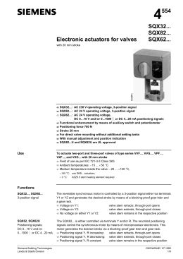
(OHFWULFURWDU\DFWXDWRUVIRUEXWWHUIO\YDOYHVDQGIRUWKUHHDQGIRXUSRUWVOLSSHU
YDOYHV
•
•
•
•
•
•
•
•
•
64.
2SHUDWLQJYROWDJH$&9
64/64/ 2SHUDWLQJYROWDJH$&9
64/64/ 2SHUDWLQJYROWDJH$&9
SRVLWLRQFRQWUROVLJQDO
$X[LOLDU\VZLWFKDQGSRWHQWLRPHWHUIRUDGGLWLRQDOIXQFWLRQV
1RPLQDODQJOHRIURWDWLRQ
5HYHUVLEOHHOHFWULFPRWRU
)RUPRXQWLQJRQEXWWHUIO\YDOYHVDQGVOLSSHUYDOYHVZLWK$6.«PRXQWLQJNLW
:LWKPDQXDODGMXVWHUDQGSRVLWLRQLQGLFDWRU
$SSOLFDWLRQ
For use in heating, ventilation and air conditioning systems to operate Landis & Staefa
butterfly valves and three-port and four-port slipper valves (mixing valves), types K1i…,
VKF…, VB… and VC. *) and valves from other manufacturers.
The actuators can be fitted with additional auxiliary switches and potentiometers
*) see "Compatibility"
CM1N4506E
05.2000
6LHPHQV%XLOGLQJ7HFKQRORJLHV
/DQGLV6WDHID'LYLVLRQ
)XQFWLRQV
If the actuator is driven by a 3-position signal from the controller, it generates a rotary
motion which is transferred to the valve (butterfly, slipper valve, three-port or four-port
mixing valve).
'LUHFWLRQRIURWDWLRQRIWKHDFWXDWRURQGHOLYHU\
Voltage at Y1 = Anti-clockwise rotation
Y2 = Clockwise rotation
No voltage
= No rotation; actuator fixed in relevant position
The direction of rotation can be reversed if required.
Extending the actuator
functions
• The SQK33.00 actuator can be fitted with an auxiliary switch
• The SQL… actuators can be fitted with an auxiliary switch, a dual auxiliary switch or
an auxiliary switch and a 1000-ohm potentiometer.
If an auxiliary switch and/or potentiometer are fitted, the electrical wiring must take
account of this. Refer to the wiring diagram under the actuator cover and see also the
"Commissioning" and "Connection diagram" sections in this data sheet.
7\SHV
Type
64.*)
64/
64/
64/
64/
64/
0RXQWLQJNLWV
$FFHVVRULHV
Operating
voltage
AC 230 V
AC 230 V
AC 230 V
AC 24 V
AC 230 V
AC 24 V
$6.
$6.
Type of
control
3-position
Run-time
for 90° at 50 Hz
125 s
3-position
125 s
30 s
125 s
125 s
125 s
Space for
accessories
Function
1 x ASC9.5 only
1 auxiliary switch
1 x ASC9.5 or
1 x ASC9.4 or
1 x ASZ7.4
1 auxiliary switch
1 dual auxiliary switch
1 auxiliary switch and
1000 Ω potentiometer
$6.
$6.
$6.
$6.
For slipper valves, type VBF21 … Series 01 (DN65 ... DN150), Series 01
For slipper valves, type VB… / VC (DN¾"... DN1½") Series 02
or VBF21... (DN40 / 50)
For butterfly valves, type VKF41… (DN40 ... DN200)
For butterfly valve types VKF41… and VKF45…(DN40 ...DN200)
For slipper valves from other manufacturers, see data sheet N4291
For slipper valves from other manufacturers, see data sheet N4291
$6&
$6&
$6=
1 auxiliary switch
1 dual auxiliary switch
1 auxiliary switch and one 1000-ohm potentiometer
2UGHULQJ
The actuator, slipper valve or butterfly valve, mounting kit and any accessories (e.g.
switches) must be ordered separately.
When ordering, please specify the quantity, product name and type code.
([DPSOH DFWXDWRUW\SH64/PRXQWLQJNLWW\SH$6. and
DX[LOLDU\VZLWFKZLWK$6=SRWHQWLRPHWHU
Delivery
The actuator, mixing valve or butterfly valve, ASK.. mounting kit and accessories are
packed separately and are not delivered fully assembled.
2/8
Siemens Building Technologies
Landis & Staefa Division
SQK33.00, SQL3..., SQL8... Electric actuators
CM1N4506E
05.2000
&RPSDWLELOLW\
The table below shows which actuators may be used with which slipper valves (mixing
valves) and butterfly valves, and indicates the appropriate mounting kits in each case.
1RP
SUHVVXUH
9DOYHV
'DWD
VKHHW
64.
[bar]
$FWXDWRUV
64/ 64/
64/
64/
64/
0RXQWLQJ
NLWV
Nominal size (DN)
7KUHHSRUW
VOLSSHUYDOYHV
(Mixing)
9%)
(40 ... 50)
PN6
N4241
40 / 50
40 / 50
40 / 50
---
$6.
(65 ...150)
PN6
N4241
---
65 ...150
65 ...150
65 ...150
$6.
9%,
(¾”...1½”)
PN10
N4232
¾”...1½”
¾”...1½”
¾”...1½”
---
$6.
9%*
(¾”...1½”)
PN10
N4233
¾”...1½”
¾”...1½”
¾”...1½”
---
$6.
PN6...
---
¾”...1½”
¾”... 2"
¾”... 2"
---
$6.*)
$6.*)
PN10
N4252
¾”...1½”
¾”...1½”
¾”...1½”
---
$6.
Other
makes
)RXUSRUW
YDOYHV
(Mixing)
9&,
(¾”...1½”)
Other
makes
PN6...
---
¾”...1½”
¾”...
¾”... 2"
---
$6.*)
$6.*)
$6.
%XWWHUIO\YDOYHV
.L
(¾”...1¼”)
PN6
N4111
¾”...1¼”
¾”...1¼”
---
---
9.)
(40 ... 200)
PN16
N4131
40
40 ... 200
40 ... 200
---
$6.
9.)
(150...200)
PN16
N4131
---
---
---
150 ... 200
$6.
(40 ... 200)
PN16
N4135
---
---
---
40 ... 200
$6.
*) Mounting kits ASK40 and ASK41 for non-Landis & Staefa actuators: refer to data sheet N42291
0HFKDQLFDOGHVLJQ
The electric actuators require no maintenance. They have a reversible synchronous
motor and reduction gears with self-lubricating sinter bearings. The housing base and
the console are die-cast aluminium, and the cover is plastic.
"AUTO" and "MANUAL" modes can be selected with a rotary switch on the housing
base. When the switch is set to "MANUAL", the actuator and valve can be operated
with a manual lever. For manual operation, the angle of rotation is mechanically limited
by an end-stop.
The actuators supplied have a 90° angle of rotation suitable for the Landis & Staefa
valves. During automatic operation, rotation is limited by two built-in end-switches. For
non-Landis & Staefa valves, the angle of rotation in the range 70° to 180° can be
selected by repositioning the switching cams.
The direction of operation of the actuator can be reversed (refer to "Commissioning").
'LVSRVDO
The valve must be dismantled and separated into its various constituent materials
before disposal.
3/8
Siemens Building Technologies
Landis & Staefa Division
SQK33.00, SQL3..., SQL8... Electric actuators
CM1N4506E
05.2000
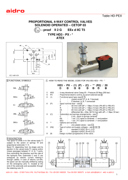
Rotary "AUTO" / "MAN" switch
Manual lever
Console (e.g. ASK31 mounting kit)
Terminal strip
Dual end-switch (always factory fitted)
Connector for reversal of direction of rotation
(only with SQK33.00, SQL33.0…, SQL83.00)
$FFHVVRU\$6&
1 auxiliary switch
$FFHVVRU\$6&
4554Z04
for SQK33.00,
SQL33.0..., SQL35.00
SQL83.00 and SQL85.00
$FFHVVRU\$6=
1 auxiliary switch and
1 1000-ohm potentiometer
4554Z05
for SQL33.0..., SQL35.00
SQL83.00 and SQL85.00
4554Z06
1 dual auxiliary switch
for SQL33.0..., SQL35.00
SQL83.00, SQL85.00
(QJLQHHULQJ
• Butterfly valves: see data sheets N4100 … N4199.
• Three-port and four-port slipper valves (mixing valves): see
data sheets N4200 … N4299.
• Admissible ambient temperatures, see "Technical data".
(OHFWULFDOLQVWDOODWLRQ
The actuators must be electrically connected in accordance with local regulations and
with the connection diagrams.
5HJXODWLRQVDQGUHTXLUHPHQWVWRHQVXUHWKHVDIHW\RISHRSOHDQGSURSHUW\PXVW
EHREVHUYHGDWDOOWLPHV
If additional functions are to be controlled by the actuator, the ASC9.. (auxiliary switch)
or ASZ7.5 (auxiliary switch / potentiometer) must be fitted. The relevant switching
point(s) and zero-ohm position must be noted in the plant documentation.
4/8
Siemens Building Technologies
Landis & Staefa Division
SQK33.00, SQL3..., SQL8... Electric actuators
CM1N4506E
05.2000
0RXQWLQJ
Mounting instructions are enclosed with the mounting kit.
The valve, actuator and mounting kit are packed separately. The valve and actuator
can be assembled easily on site. There is no need for special tools or calibration.
Take care to install the valve the right way up. Refer to the mounting instructions for the
valve concerned (butterfly or slipper valves).
Orientation
3HUPLVVLEOH
1RWSHUPLVVLEOH
&RPPLVVLRQLQJ
When commissioning the complete motorised valve, consisting of actuator, mounting kit
and (butterfly or slipper) valve, check the wiring and test the functions. This also
applies to any additional components fitted (e.g. auxiliary switch or potentiometer).
Note
Landis & Staefa slipper valves up to DN50 can be commissioned without an actuator
being fitted. In this case, the flow rate must be adjusted manually with the standard
manual adjuster fitted to the valve.
For automatic operation, the rotary switch must be set to "AUTO".
0RGHRIRSHUDWLRQ
Rotary switch for
mode selection
$872 $XWRPDWLFRSHUDWLRQ
0$1 0DQXDORSHUDWLRQ
64/64/
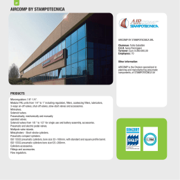
'LUHFWLRQRIURWDWLRQ
Position indication
These actuators are used exclusively to operate Landis & Staefa butterfly valve types
VKF41… and VKF45…
The actuator is factory-set to rotate in a clockwise direction (as seen from the front).
This matches the direction of rotation of the installed butterfly valve.
The adhesive labels
supplied must be applied
when assembling the
valve/actuator
%XWWHUIO\YDOYHLQ
23(1SRVLWLRQ
5HYHUVLQJWKH
GLUHFWLRQRIURWDWLRQ
%XWWHUIO\YDOYHLQ
&/26('SRVLWLRQ
The actuators are factory-set to rotate in a clockwise direction (as seen from the front).
The direction of rotation can be reversed by repositioning a connector located under the
cover (see "Mechanical design").
The wiring for the OPEN and CLOSE control signal is not affected.
5/8
Siemens Building Technologies
Landis & Staefa Division
SQK33.00, SQL3..., SQL8... Electric actuators
CM1N4506E
05.2000
$VVXSSOLHG
6HWWLQJWKHDQJOHRI
URWDWLRQ
'LUHFWLRQRIURWDWLRQUHYHUVHG
The angle of rotation is factory-set to 90°. However, the angle can be changed to
between 70° and 180°. This may be necessary when using non-Landis & Staefa valves.
Special notes on this subject will be found in the mounting instructions for the ASK40
and ASK41 (mounting kits for non-Landis & Staefa valves).
0DLQWHQDQFH
:DUQLQJ
When servicing the valve and/or actuator: switch OFF the pump and power supply,
close the main shut-off valve in the pipework, release pressure in the pipes and allow
them to cool down completely.
If necessary, disconnect electrical connections from terminals.
:DUUDQW\
The technical data given for these applications is valid only in conjunction with the
Landis & Staefa valves (butterfly and slipper valves) and third-party valves for use with
the ASK40 / ASK41, as described under "Compatibility". The use of third-party valves
other than those recommended by Landis & Staefa invalidates the warranty.
7HFKQLFDOGDWD
Power supply
Operating data
Operating voltage
SQK33.00, SQL33.00, SQL33.03, SQL35.00
SQL83.00, SQL85.00
Frequency
Type of control
Power consumption *)
SQK33.00
SQL33.00, SQL83.00
SQL33.0..., SQL35.00, SQL85.00
Run-time for rotation through 90°
SQK33.00, SQL33.00, SQL35.00
SQL83.00, SQL85.00
SQL33.03
Angle of rotation
Factory setting
Adjustment range
AC 230 V ± 15 %
AC 24 V ± 20 %
50 / 60 Hz
3-position
3 VA
4 VA
6.5 VA
DW+]
125 s
125 s
30 s
DW+]
105 s
105 s
25 s
90° ± 2°
70° ...180°
6/8
Siemens Building Technologies
Landis & Staefa Division
SQK33.00, SQL3..., SQL8... Electric actuators
CM1N4506E
05.2000
Materials
Dimensions / Weight
Ambient conditions
Industry standards
Accessories
Torque *)
SQK33.00
SQL33.03
SQL33.00, SQL83.00
SQL35.00, SQL85.00
End switch
Switching capacity
Switching differential
Housing base and console
Cover
Dimensions
Cable glands
Weight
SQK33.00
SQL33.00, SQL83.00
SQL33.03, SQL35.00, SQL85.00
Max. admissible temperature of medium in
assembled valve
Operation
– Environmental conditions
– Temperature
– Humidity
Transport
– Environmental conditions
– Temperature
– Humidity
Storage
– Environmental conditions
– Temperature
– Humidity
Meets the requirements for &( marking in
EMC Directive
Low Voltage Directive
Housing protection standard
$6&
$6&
Switching capacity
Switching differential
$6=
Switching capacity
Switching differential
Change in resistance
1RPLQDOWRUTXH
5 Nm
10 Nm
12.5 Nm
20 Nm
6WDUWLQJWRUTXH
10 Nm
12 Nm
25 Nm
40 Nm
AC 250 V, 6 (2) A
Approx. 1°
Die-cast aluminium
Plastic
See “Dimensions”
Pg11 (4x)
1.25 kg
1.35 kg
1.40 kg
> 120 °C
To IEC 721-3-3
Class 3K5
–15 ... +55 °C
5 ... 95 % rh
To IEC 721-2-3
Class 3K2
– 30 ... +65 °C
< 95 % rh
To IEC 721-1-3
Class 3K1
–15 ... +55 °C
0 ... 95 % rh
89/336/EEC
73/23/EEC
IP44 to IEC529 / DIN40050
Auxiliary switch
Dual auxiliary switch
AC 250 V,
6 A resistive / 3 A inductive
Approx. 1°
Auxiliary switch with potentiometer
AC 250 V, 6 (3) A
Approx. 1°
0 ... 90° corresponding to
0 ...1000 ohm
*) These values apply at nominal voltage, at an ambient temperature of 20°C and at the
specified nominal running time
7/8
Siemens Building Technologies
Landis & Staefa Division
SQK33.00, SQL3..., SQL8... Electric actuators
CM1N4506E
05.2000
&RQQHFWLRQGLDJUDPV
64.
64/64/
64/64/64/
Cm1
Cm2
c1
c1, c2
c1, 1000Ω
End switch
End switch
1 auxiliary switch $6&or
1 dual auxiliary switch $6&
or
1 installable module $6=
(1 auxiliary switch and
1 potentiometer)
'LPHQVLRQV
All dimensions in mm
64.
Installation height H*
for actuator with mounting kit
ASK31
162 mm
ASK32
132 mm
ASK33
162 mm
64/64/
Installation height H*
for actuator with mounting kit
ASK31
188 mm
ASK32
158 mm
ASK33
188 mm
64/64/
Installation height H*
for actuator and mounting kit
ASK35
233 mm
Overall height of valve
and actuator
= Installation height of slipper or butterfly valve from the middle of the pipe
+ Installation height H* of the actuator with mounting kit
+ Minimum clearance from ceiling or wall for mounting, connection,
operation, service etc.
∆
>100 mm
∆ ∆ >200 mm
2000 Siemens Building Technologies Ltd.
8/8
Subject to technical alteration
Siemens Building Technologies
Landis & Staefa Division
SQK33.00, SQL3..., SQL8... Electric actuators
replace CM1N4506E and CM1N4507E
CM1N4506E
05.2000
4
Actuator for L&S
Slipper Valves up to
DN50 AC 230 V
Siemens Building Technologies
Landis & Staefa Division
508
SQK34...
CM1N4508E / 12.1998
1/4
CM1N4508E / 12.1998
2/4
Siemens Building Technologies
Landis & Staefa Division
Siemens Building Technologies
Landis & Staefa Division
CM1N4508E / 12.1998
3/4
1998 Siemens Building Technologies Ltd.
CM1N4508E / 12.1998
4/4
Replaces CE1N4508E
Siemens Building Technologies
Landis & Staefa Division
Scaricare