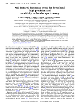
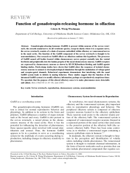
Optical Materials 31 (2009) 1071–1074
Contents lists available at ScienceDirect
Optical Materials
journal homepage: www.elsevier.com/locate/optmat
Er3+-activated nanocomposite photonic glasses and confined structures
C. Armellini a, A. Chiappini a, A. Chiasera a,*, M. Ferrari a, Y. Jestin a, E. Moser b, G. Nunzi Conti c,d, S. Pelli d,
A. Quandt a,e, G.C. Righini d,f, C. Tosello b
a
CNR-IFN, Institute of Photonics and Nanotechnology, CSMFO Group, via Sommarive 14, 38050 Povo-Trento, Italy
Physics Department, Trento University, CSMFO Group, via Sommarive 14, 38050 Povo-Trento, Italy
c
Centro Fermi, Complesso del Viminale, 00184 Roma, Italy
d
CNR-IFAC, Nello Carrara Institute of Applied Physics, via Madonna del Piano 10, 50019 Sesto Fiorentino-Firenze, Italy
e
Institut fuer Physik, Universitaet Greifswald, Hausdorff-Str. 6, 17489 Greifswald, Germany
f
CNR, Materials and Devices Department, via dei Taurini 19,00185 Roma, Italy
b
a r t i c l e
i n f o
Article history:
Available online 8 May 2008
Keywords:
Nanocomposites glasses
Erbium
Sol–gel
1D photonic crystals
Photoluminescence
a b s t r a c t
This paper reports about recent advances in optical nanomaterials and planar microcavities. Bottom-up
fabrication, optical and spectroscopic assessment of Er3+-activated SiO2–HfO2 waveguide glass ceramic
are presented. Concerning confined structures, the rf sputtering based fabrication of an Er3+-activated
microcavity with a quality factor of 171 using oxide-based dielectric materials is demonstrated.
Ó 2008 Elsevier B.V. All rights reserved.
1. Introduction
The last decade has seen a remarkable increase in the experimental efforts to control and enhance the emission properties of
various emitters, in particular Er3+-ions, by tailoring the dielectric
surrounding of the sources. With this aim, several approaches,
using nanocomposite materials [1–3] and specific geometries, such
as planar interfaces [4], photonic crystals [5,6], solid state planar
microcavities [5,7,8], dielectric nanospheres [9,10], and spherical
microresonators [11,12], have been proposed, which open new
possibilities in the field of basic as well as applied physics, and
other areas including Information Communication Technologies,
Health and Biology, Structural Engineering, and Environment Monitoring Systems.
Nanostructured materials have sparked great interest among
the academic and industrial communities over the past decade,
due to the remarkable variations in the fundamental electrical,
optical and magnetic properties that occur during the transition
from a bulk ‘‘homogeneous” material to a particle or a cluster within the 1–100 nm range. Moreover, the possibility to develop optically confined structures would allow for novel optical
components, and the glass-based planar technology appears to
be consolidated enough to allow the design of complex optical de* Corresponding author.
E-mail address: [email protected] (A. Chiasera).
0925-3467/$ - see front matter Ó 2008 Elsevier B.V. All rights reserved.
doi:10.1016/j.optmat.2007.12.017
vices [1]. A more effective control of luminescence properties may
be achieved by rare earth-activated microcavities, which represent
a particular class of photonic crystals [5].
The aim of this paper is to give an overview of the advances in
glass-based photonic systems, where light confinement or the
presence of nanostructured hosts induces an enhancement of optical and/or spectroscopic properties of the rare earth ions. In particular, the following topics will be highlighted: (i) dielectric 1D
photonic band gap structures or planar microcavities, characterized by a high quality factor Q; (ii) Er3+-activated glass ceramics
planar waveguides obtained by innovative bottom-up technique.
2. Dielectric 1D microcavity
In this section we report on an Er3+-codoped all-dielectric
microcavity fabricated by rf sputtering (RFS) and operating at
1544 nm.
The microcavity consists of a SiO2 half-wave layer inserted between two Bragg reflectors composed of a stack of six pairs of alternated SiO2 and TiO2 quarter-wave layers. Each SiO2 layer is
activated with 0.3 at% of Er3+ ions, as measured by energy dispersive spectroscopy (EDS) using a Noran Instruments mod. Voyager
apparatus. The refractive index at 1542 nm of the silica and titania
layers, measured by m-line spectroscopy on the single films, was
1.444 ± 0.002 and 2.30 ± 0.02, respectively. To increase the reflection coefficient of the distributed Bragg reflectors (DBRs), the index
contrast between the two materials should be as large as possible,
and TiO2 and SiO2 have been chosen [5]. The samples were deposited on silicon and silica substrates. The sample deposited on silicon was employed for SEM measurements. The sample deposited
on a silica substrate was employed for transmittance and photoluminescence measurements. In order to improve the adhesion of
the films, the substrates were cleaned inside the RFS deposition
chamber by removing some atomic layers just before the deposition procedure: in this pre-sputtering stage the face of the substrates is exposed to the plasma for 10 min. Sputtering
deposition of the films was performed by sputtering alternatively
a 400 titania target and a 400 silica target on which metallic erbium
pieces were placed. The deposition time required to reach the
appropriate thicknesses of the Bragg grating layers was 14 min
15 s for the titania target and 11 min 15 s for the silica target.
The deposition time required to reach the appropriate thickness
of the silica defect layer leading to a cavity resonance centered at
1.5 lm, was 25 min. The residual pressure, before deposition, was
about 2 107 mbar. During the deposition process the substrates
were not heated. The sputtering occurred with an Ar pressure of
5 103 mbar; the applied rf power was 150 W, with a reflected
power of 16 W and 0 W for silica and titania targets, respectively.
A SEM image of the cross section of the cavity fabricated with
this protocol is shown in Fig. 1. The dark regions correspond to
the SiO2 layers and the bright ones to the TiO2 layers. It is possible
to identify the defect layer and the two Bragg reflectors. The SEM
image allowed us to measure a thickness of 210 ± 5 nm and
195 ± 5 nm for the silica and titania layers of the Bragg mirrors,
and a thickness of 490 ± 5 nm for the SiO2 defect layer.
The transmittance spectrum of the cavity, obtained by using a
Varian-Carry spectrophotometer, is shown in Fig. 2. The spectral
reflection range, i.e. the stop band, lies from 1350 to 1850 nm. A
sharp peak in the transmittance spectrum appears at 1544 nm. It
corresponds to the cavity resonance wavelength related to the half
wave layer inserted between the Bragg mirrors.
Fig. 3 compares the 4I13/2 ? 4I15/2 PL spectrum of the cavity activated by Er3+ ions to the PL spectrum of the single Er3+-doped SiO2
active layer without Bragg mirrors. Both the cavity and no-cavity
structures were excited with the 514 nm line of an Ar+ ion laser with
an excitation power of 100 mW. The luminescence was dispersed by
a 320 mm single-grating monochromator with a resolution of 1 nm.
The light was detected using a Hamamatsu photomultiplier tube and
standard lock-in technique. For this analysis, the samples are fixed
on a rotating holder. The PL from the cavity and from the Er3+-doped
single SiO2 layer were detected at 5° from the normal on the samples,
with a solid angle of 101 steradian. The erbium emission from the
no-cavity single SiO2 active layer is centered at 1538 nm with a full
width at half maximum (FWHM) of 28 nm and exhibits the characteristic shape of erbium ion emission in silica glass [13]. The cavity
Transmission coefficient [%]
C. Armellini et al. / Optical Materials 31 (2009) 1071–1074
10
0
1300
1400
1500
1600
1700
1800
1900
Wavelength [nm]
Fig. 2. Transmittance spectrum of the cavity with a six doublets Bragg mirror. The
stop band extends from 1350 to 1850 nm. The cavity resonance corresponds to the
sharp maximum at the center of the transmission window. The incident light is
non-polarized.
Photonic Crystal
Defect X 90
Intensity [arbitrary units]
1072
1400
1500
1600
1700
Wavelength [nm]
Fig. 3. 4I13/2 ? 4I15/2 photoluminescence spectra of the cavity activated by Er3+ ion
(1D photonic crystal) and of the single Er3+-doped SiO2 active layer without Bragg
mirrors (defect). The light is recorded at 5° from the normal with respect to the
samples, and upon excitation at 514.5 nm.
resonance is strongly dependent on the detection angle [14]. For a
detection angle of 5°, the cavity resonance corresponds to the maximum of the erbium PL of the no-cavity SiO2 active layer. The peak
luminescence intensity of Er3+ ions is enhanced by a factor 90, with
respect to the no-cavity case at the same wavelength. The
Er3+ 4I13/2 ? 4I15/2 PL line shape is strongly modified by the cavity,
and the Er3+ emission is enhanced when the wavelength corresponds to the cavity resonant mode, but weakens for the other emission wavelengths. A sharp line is observed for PL spectrum from the
cavity, as shown in Fig. 3. The FWHM is 9 nm, corresponding to a
quality factor of the cavity, Q, equal to 171, assuming the absence
of photon re-absorption [7,15].
3. Bottom-up glass-ceramic planar waveguides
Fig. 1. Cross section image of the sample obtained using scanning electron microscopy. The bright and the dark areas are TiO2 and SiO2 layers, respectively [5].
Ceramic glassy materials may be a valid alternative to control
the chemical parameters of the rare earth components, thus avoiding undesirable effects like clustering. Using a bottom-up approach
SiO2–HfO2:Er3+ glass-ceramic planar waveguides were realized by
following the described protocol: (1) preparation of a colloidal
suspension of HfO2 nanoparticles, starting from a HfOCl2 solution
1073
in ethanol and using a reflux technique; (2) separation of HfO2
nanoparticles from the colloidal suspension; (3) preparation of a
solution of TEOS, alcohol, deionised water and hydrochloridric acid
prehydrolized for 1 h at 65°C, in which has been added the hafnia
precursor HfOCl2 in order to obtain a final solution with a molar
ration Si/Hf = 80/20; 4) to this solution Er(NO3)3 5H2O has been
added with a molar concentration Er/(Si+Hf) = 1 as well as hafnia
nanoparticles, in order to obtain 2.5 mol% of nanoparticles in the
solution [1]. Nanocomposite planar waveguides were produced
by dip-coating the final solution on a SiO2 substrate, stabilized by
a thermal treatment at 900 °C in air for 22 h (see Table 1).
After the introduction of hafnia nanoparticles in the silica–hafnia sol, a HRTEM image (Fig. 4) of the produced waveguide has
been made, which shows nanocrystals of about 3–4 nm in size
homogeneously scattered over the amorphous matrix. This shows
the feasibility of a bottom-up approach for the production of nanocomposite waveguides.
The EDS analysis has confirmed that the nanocrystals are composed of hafnium oxide. Fig. 5 compares the 4I13/2 ? 4I15/2 PL spectrum of the waveguide glass-ceramic (WGC) activated by Er3+ ions,
and the PL spectrum of a silica–hafnia Er3+-activated waveguide
without nanocrystals (WG). The 4I13/2 ? 4I15/2 photoluminescence
spectrum of the nanocomposite waveguide indicates that the ordering of the local environment limits the inhomogeneous broadening
typical of glassy structural environments. In fact, the FWHM is
27 nm for the glass ceramic as compared to the 45 nm measured
for the amorphous system [1]. We can assume that the thermal treatment at 900 °C, which does not damage the surface of the film, has
promoted the migration of erbium ions towards the hafnia nanocrystals [16]. The lifetime of the metastable level 4I13/2 has been measured at 1532 nm. The decay curve presents a single exponential
behaviour with a lifetime of 5.6 ms, as compared to 4.5 ms measured
for the amorphous waveguide [1]. Because the hafnia cut-off frequency is around 700 cm1, the main effect of the presence of nanocrystals is a reduction of the nonradiative processes, thus inducing a
lengthening of the lifetime for the metastable level 4I13/2. The bot-
Table 1
Annealing temperature, size of nanocrystals, attenuation coefficient, and
lifetime of the Er3+-activated SiO2–HfO2 glass ceramic planar waveguide
Thermal treatment (°C)
Crystallites size (±1 nm)
Losses at 1542 nm (±0.3 dB/cm)
Lifetime at 1532 nm (ms)
4
I13/2
900
3–4
0.3
5.6
Intensity [arb.units]
C. Armellini et al. / Optical Materials 31 (2009) 1071–1074
WG
WGC
1400
1450
1500
1550
1600
1650
1700
Wavelength [nm]
Fig. 5. Room temperature luminescence spectra of the 4I13/2 ? 4I15/2 transition of
Er3+ ions for a glass-ceramic waveguide (WGC) and an amorphous planar waveguide (WG), obtained by exciting the TE0 mode at 514.5 nm.
tom-up waveguide shows excellent propagation properties at
1.5 lm with losses around 0.3 dB/cm, which will make it a suitable
component for low losses amplifier in the C band of telecommunication. It is important to note that the bottom-up method will allow for
a clear amelioration of the optical properties of glass-ceramic waveguides as compared to waveguides obtained by the standard topdown method. The top-down method requires a high thermal treatment at 1000 °C, to grow nanocrystals in the matrix, and it induces
optical losses of 1 dB/cm at 1542 nm, caused by a degradation of
the waveguide surface [17].
4. Conclusions
Using the rf sputtering technique, we fabricated via an Er3+activated microcavity with a quality factor of 171 using Er3+doped-SiO2 and TiO2 thin films. The transmittance spectrum shows
a cavity resonance centered at 1544 nm with a stop band from
1350 to 1850 nm. Er3+ luminescence enhancement of 90 times
was observed, caused by the cavity effect.
Concerning glass ceramics, we have defined a fabrication protocol by sol–gel route of rare earth activated glass-ceramic planar
waveguides. The waveguides have been realized using a bottomup technique. Optical measurements have evidenced that glass
ceramics containing nanocrystals of about 3 nm may exhibit a
low attenuation coefficient of 0.3 dB/cm at 1542 nm.
Acknowledgements
The work reported in this paper was partially supported by PAT
(2004–2006) FAPVU, CNR-CNRS 2005–2007, and PAT FaStFAL
(2007–2009) research projects.
References
Fig. 4. HRTEM image of the glass-ceramic waveguide showing HfO2 nanocrystals
scattered over the amorphous matrix.
[1] Y. Jestin, C. Armellini, A. Chiasera, A. Chiappini, M. Ferrari, E. Moser, R. Retoux,
G.C. Righini, Appl. Phys. Lett. 91 (2007) 071909-1/3.
[2] V.K. Tikhomirov, D. Furniss, A.B. Seddon, I.M. Reaney, M. Beggiora, M. Ferrari,
M. Montagna, R. Rolli, Appl. Phys. Lett. 81 (2002) 1937.
[3] R. Serna, A. Suarez-Garcia, M. Jiménez de Castro, C.N. Afonso, Appl. Surf. Sci.
247 (2005) 8.
[4] E. Snoeks, A. Lagendijk, A. Polman, Phys. Rev. Lett. 74 (1995) 2459.
[5] A. Chiasera, R. Belli, S.N.B. Bhaktha, A. Chiappini, M. Ferrari, Y. Jestin, E. Moser,
G.C. Righini, C. Tosello, Appl. Phys. Lett. 89 (2006) 171910/1.
[6] J. Kalkman, E. de Bres, A. Polman, Y. Jun, D.J. Norris, D.C. ‘t Hart, J.P.
Hoogenboom, A. van Blaaderen, J. Appl. Phys. 95 (2004) 2297.
[7] J. Bellessa, S. Rabaste, J.C. Plenet, J. Dumas, J. Mugnier, O. Marty, Appl. Phys.
Lett. 79 (2001) 2142.
[8] A.M. Vredenberg, N.E. Hunt, E.F. Schubert, D.C. Jacobson, J.M. Poate, G.J. Zydzik,
Phys. Rev. Lett. 71 (1992) 517.
1074
C. Armellini et al. / Optical Materials 31 (2009) 1071–1074
[9] H. Schniepp, V. Sandoghdar, Phys. Rev. Lett. 89 (2002) 257403-1/4.
[10] A. Chiappini, C. Armellini, A. Chiasera, M. Ferrari, Y. Jestin, M. Mattarelli, M.
Montagna, E. Moser, G. Nunzi Conti, S. Pelli, G.C. Righini, M. Clara Goncßalves,
Rui M. Almeida, J. Non-Cryst. Solids 353 (2007) 674.
[11] L. Yang, T. Carmon, B. Min, S.M. Spillane, K.J. Vahala, Appl. Phys. Lett. 86 (2005)
091114-1/3.
[12] G.C. Righini, C. Armellini, A. Chiasera, Y. Jestin, M. Ferrari, A. Chiappini, M.
Montagna, C. Arfuso Duverger, P. Féron, S. Berneschi, M. Brenci, G. Nunzi Conti,
S. Pelli, C. Goncßalves, Rui M. Almeida, Glass Technol. – Eur. J. Glass Sci. Technol.
Part A 48 (2007) 200.
[13] W.J. Miniscalco, J. Lightwave Technol. 9 (1991) 234.
[14] K.M. Chen, A.W. Sparks, H.-C. Luan, D.R. Lim, K. Wada, L.C. Kimerling, Appl.
Phys. Lett. 75 (1999) 3805.
[15] H. Rigneault, C. Amra, S. Robert, C. Begon, F. Lamarque, B. Jacquier, P. Moretti,
A.M. Jurdyc, A. Belarouci, Opt. Mater. 11 (1999) 167.
[16] W.C. Liu, D. Wu, A.D. Li, H.Q. Ling, Y.F. Tang, N.B. Ming, Appl. Surf. Sci. 191
(2002) 181.
[17] Y. Jestin, C. Armellini, A. Chiappini, A. Chiasera, M. Ferrari, C. Goyes, M.
Montagna, E. Moser, G. Nunzi Conti, S. Pelli, R. Retoux, G.C. Righini, G.
Speranza, J. Non-Cryst. Solids 353 (2007) 494.
Scaricare