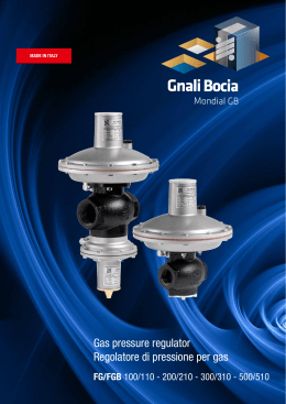
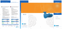
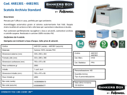
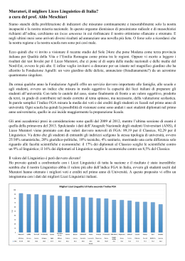
copertina 1
21-05-2007
08:05
Pagina 1
High head. High efficiency.
Wide spherical clearance.
ELETTROPOMPE
SOMMERGIBILI
GIRANTE VORTEX
0,37 - 5,5 kW
Alta prevalenza. Alti rendimenti.
Ampi passaggi liberi.
FGa 1078
APPLICAZIONI
Le elettropompe con girante vortex sono state progettate
per il sollevamento di acque di drenaggio, acque sporche
e di fognatura, acque di rifiuto domestico, artigianale
e industriale con solidi in sospensione fino a 65 mm di diametro,
materiali filamentosi e viscosi con presenza di aria, gas
e particelle abrasive, fanghi grezzi o fermentati, fanghi attivi.
APPLICATIONS
The pumps with vortex impeller have been designed
for the handling of drainage, dirty and sewage water,
domestic artisan and industrial waste waters with suspended
solids in up to 65 mm, filamentous and viscous materials
together with air, gas and abrasive particles,
rough or fermented slimes, active muds.
INSTALLAZIONE
- Mobile.
- Fissa con piede di accoppiamento.
La versione con regolatore di livello consente l’utilizzo
automatico con l’impiego del quadro di comando
AET-AEM disponibile su richiesta.
INSTALLATION
- Movable.
- Fixed installation with low level coupling.
The execution with float switch assures automatic operation
though the connection to the electrical panel type AET-AEM
available on demand.
FUNZIONAMENTO
Continuo con motore immerso
(vedere disegno di ingombro quota P4).
OPERATION
Continuous duty with submerged motor
(ref. P4 of dimension size drawing).
OPTIONAL
Disponibili a richiesta versioni con motore antideflagrante.
Protezione termica negli avvolgimenti.
Sonda di rilevamento di eventuale acqua nella camera olio.
OPTIONAL
Available on request explosion-proof executions.
Thermal protection device in the motor winding.
Catching probe for the eventual presence of water
in the oil chamber.
Corpo Pompa
Corpo Motore
Girante
Coperchio
Albero
Guarnizioni, Or
Cavo
Viteria
MATERIALI COSTRUTTIVI
Ghisa EN-GJL-250
Ghisa EN-GJL-250
Ghisa EN-GJL-250
Ghisa EN-GJL-250
X30 Cr13 (AISI 420)
NBR
H07 RNF
Inox A2 AISI 304
LIMITI D’IMPIEGO
Max. temperatura impiego
Servizio
Max. avviamenti ora
Max. profondità immersione
Ph liquido
Viscosità liquido
Densità liquido
Max. pressione acustica
Pump housing
Motor housing
Impeller
Cover
Shaft
O-rings garnitures
Cable
Screws
CONSTRUCTION MATERIALS
Cast iron EN-GJL-250
Cast iron EN-GJL-250
Cast iron EN-GJL-250
Cast iron EN-GJL-250
X30 Cr13 (AISI 420)
NBR
H07 RNF
Inox A2 AISI 304
APPLICATION LIMITS
Max. application temperature
40 °C
Operation
S1 submersible
Max. startings per hour
20
Max. immersion depth
20 m
Ph liquid
From 6 up to 12
Liquid viscosity
1 mm 2/s
Liquid density
1 Kg /dm 3
Max. acustic pression
< 70 dB
40 °C
S1 sommerso
20
20 m
Da 6 a 12
1 mm 2/s
1 Kg /dm 3
< 70 dB
VORTEX IMPELLER
SUBMERSIBLE
PUMPS
Serie FG
Riserva di modifiche senza preavviso - Subject to change without notice
FGb 1014
Serie FG
FG 600
0,37 - 5,5 kW
Mandata - Discharge
1” 1/2 - 2”1/2 DN 50-65
FABBRICA ITALIANA POMPE SOMMERGIBILI S.r.l
CODICE IDENTIFICAZIONE PRODOTTO - PRODUCT IDENTIFICATION CODE
F.I.P.S. S.r.l.
Produzione F.I.P.S.
F.I.P.S. production
Girante Vortex
Vortex impeller
Nome serie
Series name
Giri motore
Motor speed
Monofase
Single-phase
Automatico
Automatic
Viale Toscana, 46 - 20089 ROZZANO (Milano)
Tel. +39 02.82.58.923 - +39 02.57.51.03.71
Fax +39 02.57.51.20.95
www.fips-pumps.it - [email protected]
FABBRICA ITALIANA POMPE SOMMERGIBILI S.r.l
3
FABBRICA ITALIANA POMPE SOMMERGIBILI S.r.l
2007/05
F Gb 250 -2 m (A)
www.fips-pumps.it
copertina 1
21-05-2007
08:05
Pagina 2
CARATTERISTICHE
COSTRUTTIVE
TECHNICAL
FEATURES
DIMENSIONI DI
INSTALLAZIONE
INSTALLATION
SIZES
DISEGNI DI
INGOMBRO
DIMENSION
DRAWINGS
FGb 250-311-518
Versione fissa
Fixed installation
FGb 50-65
Versione mobile
Movable installation
Versione fissa
Fixed installation
Versione mobile
Movable installation
Dimensioni di installazione mm - Installation sizes mm
Motore completamente sommerso a tenuta stagna
Fully submersible pressure tight electric motor
Classe di isolamento H. Grado di protezione IP 68
Giri: 2850 al min -1
Voltaggio: monofase 1x230V-50 Hz e trifase 3x380/415V-50 Hz
Altri voltaggi e frequenze a richiesta. Certificazione ATEX in corso
Insulation class H. Protection degree IP 68
Speed: 2850 rpm. Voltage: single-phase 1x230V-50 Hz
Three-phase 3x380/415V-50 Hz. Different voltage and frequency
on request. ATEX certification in progress
Albero in acciaio AISI 420
Cuscinetti sovradimensionati lunga vita
Doppia tenuta meccanica in camera d’olio + paraolio
Shaft in stainless steel AISI 420
Bearings over-dimensioned long-life
Double mechanical seal in oil chamber + radial lipseal
Lato acqua: carburo di silicio/carburo di silicio
Lato motore: grafite/allumina
Water side: silicon carbide/silicon carbide
Motor side: graphite/alumina
Girante Vortex in ghisa ad alta prevalenza
Cavo H07RNF
Protezione termica di serie nella versione monofase
Condensatore fino a 30.000 ore di funzionamento
(esterno per pompa n. 7)
Galleggiante
AET-AEM quadro elettrico per versione trifase e monofase
Ispezione olio
Controllo tenuta stagna motore
Impeller high head cast iron Vortex
Modello - Type
A
max A1
A3
A2 max
1
FGb 250-2 m (A)
350
130
1
FGb 250-2
350
2
FGb 276-2 m (A)
350
2
FGb 276-2
350
3
FGb 301-2 m (A)
3
B
B1
B2
C
C1
C2
D
D1
E*
F
F2
F3
H
J
X
Ø
Y
Z
Z1
Z2
Z3
Z4
Z5
Z6 DN2 DN3 DN4 P3
P4
V
KG
160
150
340
100
60
1” 1/2
1” 1/2
1” 1/2 14
130
160
150
340
100
60
1” 1/2
1” 1/2
1” 1/2 14
130
160
150
340
100
60
1” 1/2
1” 1/2
1” 1/2 14
130
160
150
340
100
60
1” 1/2
1” 1/2
1” 1/2 14
350
130
160
150
340
100
60
1” 1/2
1” 1/2
1” 1/2 14
FGb 301-2
350
130
160
150
340
100
60
1” 1/2
1” 1/2
1” 1/2 14
4
FGb 311-2 m (A)
405
130
183
165
355
89
90
1” 1/2
1” 1/2
1” 1/2 20
4
FGb 311-2
405
130
183
165
355
89
90
1” 1/2
1” 1/2
1” 1/2 20
5
FGb 317-2 m (A)
405
130
183
165
355
89
90
1” 1/2
1” 1/2
1” 1/2 20
5
FGb 317-2
405
130
183
165
355
89
90
1” 1/2
1” 1/2
1” 1/2 20
6
FGb 512-2 m (A)
425
130
190
175
355
89
105
2”
2”
6
FGb 512-2
425
130
190
175
355
89
105
2”
2”
2”
24
7
FGb 518-2 ms (A)
425
130
190
175
355
89
105
2”
2”
2”
24
7
FGb 518-2
425
130
190
175
355
89
105
2”
2”
2”
24
8
FGb 50.0,8-2 m (A)
410
130 368
200
400
77
150 290
2”
2”
250 445 50
22
8
FGb 50.0,8-2
410
130 368
200
400
77
150 290
2”
2”
250 445 50
22
2”
24
9
FGb 50.1,2-2 ms (A)
430
130 388
200
400
77
150 290
2”
2”
270 465 50 23,5
10
FGb 50.1,2-2
430
130 388
200
400
77
150 290
2”
2”
270 465 50 23,5
11
FGb 50.2,6-2
460
130 418
200
400
77
150 290
2”
2”
245 495 50
12
FGb 65.0,8-2 m (A)
435
130 385
200
400
70
175 306
2” 1/2
2” 1/2 282 478 50◆ 23
12
FGb 65.0,8-2
435
130 385
200
400
70
175 306
2” 1/2
2” 1/2 282 478 50◆ 23
FGb 65.1,2-2 ms (A)
455
130 405
200
400
70
175 306
2” 1/2
2” 1/2 302 498 50◆ 24,5
14
FGb 65.1,2-2
455
130 405
200
400
70
175 306
2” 1/2
2” 1/2 302 498 50◆ 24,5
15
FGb 65.1,85-2
485
130 455
200
400
70
175 306
2” 1/2
2” 1/2 303 428 50◆ 31,5
16
FGb 65.2,6-2
505
130 455
200
400
70
175 306
2” 1/2
2” 1/2 297 548 50◆ 38
2” 1/2
2” 1/2 297 548 50
17
FGb 65.2,6-2 HT
505
130 435
200
400
70
175 306
18
FGb 615-2 ms
400
130
240 135
230 115
420 165 85
80 175 330
101 26,9 70
110 90
75 210 435 50
31
19
FGb 615-2
440
130
240 135
230 115
420 165 85
80 175 330
101 26,9 70
110 90
75 250 475 50
30
20
FGb 625-2
400
130
240 135
230 115
420 165 85
80 175 330
101 26,9 70
110 90
75 210 435 50
32
FGb 630-2
440
130
240 135
230 115
420 165 85
80 175 330
101 26,9 70
110 90
75 225 475 50
35
45
22
FGb 640-2
465
130
240 135
230 115
420 165 85
80 175 330
101 26,9 70
110 90
75 230 500 50
FGa 610-4 ms
400
130
240 135
230 115
420 165 85
80 175 330
101 26,9 70
110 90
75 210 435 50
31
FGb 1000
23
FGa 610-4
400
130
240 135
230 115
420 165 85
80 175 330
101 26,9 70
110 90
75 210 435 50
30
Versione mobile
Movable installation
24
FGa 615-4
400
130
240 135
230 115
420 165 85
80 175 330
101 26,9 70
110 90
75 210 435 50
32
25
FGa 620-4
440
130
240 135
230 115
420 165 85
80 175 330
101 26,9 70
110 90
75 225 475 50
35
26
FGb 1016-1,1-2 ms
475 300 160
250 154 255 220 110 55 635 355 100 59 105 205 400 134 130 42,4 84 100 14
90 100 15 140
65
75 320 510 65
31
26
FGb 1016.1,1-2
475 300 160
250 154 255 220 110 55 635 355 100 59 105 205 400 134 130 42,4 84 100 14
90 100 15 140
65
75 320 510 65
31
27
FGb 1026.1,85-2
475 300 160
250 154 255 220 110 55 635 355 100 59 105 205 400 134 130 42,4 84 100 14
90 100 15 140
65
75 320 510 65
33
28
FGb 1031.2,6-2
485 300 160
250 145 242 220 110 55 635 355 100 59 105 205 400 134 130 42,4 84 100 14
90 100 15 140
65
75 310 525 65
40
29
FGb 1056.4-2
505 325 168
270 148 258 240 220 72 707 430 108 59 105 205 425 160 145 60,3 95 150 14 120 120 15 175
80
75 345 555 80
51
30
FGb 1010.0,8-2 m
470 300 160
250 145 242 220 110 55 635 356 100 59 105 205 400 134 130 42,4 84 100 12
65
75 330 510 65
24
30
FGb 1010.0,8-2
470 300 160
250 145 242 220 110 55 635 356 100 59 105 205 400 134 130 42,4 84 100 12
90
96
15 132
65
75 330 510 65
24
31
FGb 1014.1,1-2 ms
470 300 160
250 145 242 220 110 55 635 356 100 59 105 205 400 134 130 42,4 84 100 12
90
96
15 132
65
75 320 510 65
25
31
FGb 1014.1,1-2
470 300 160
250 145 242 220 110 55 635 356 100 59 105 205 400 134 130 42,4 84 100 12
90
96
15 132
65
75 320 510 65
25
32
FGb 1025.1,85-2
470 300 160
250 145 242 220 110 55 635 356 100 59 105 205 400 134 130 42,4 84 100 14
90 100 15 140
65
75 320 515 65
33
40
96
15 132
33
FGb 1030.2,6-2
485 300 160
250 145 242 220 110 55 635 355 100 59 105 205 400 134 130 42,4 84 100 14
90 100 15 140
65
75 310 525 65
34
FGb 1057.4-2
505 325 168
270 148 258 240 220 72 707 430 108 59 105 205 425 160 145 60,3 95 150 14 120 120 15 175
80
75 345 555 80
51
35
FGb 1077.5,5-2
590 325 168
320 165 265 300 150 106 780 430 108 80 125 225 460 160 145 60,3 95 150 14 120 120 15 175
80
75 345 620 80
58
Thermal protection standard in the single phase execution
36
FGa 1015.1,1-4
475 300 160
260 154 255 220 110 55 635 356 113 59 105 205 400 134 130 42,4 84 100 12
50
96
15 132
65
75 330 515 65
39
37
FGa 1020.1,5-4
475 300 160
250 154 255 220 110 55 635 356 113 59 105 205 400 134 130 42,4 84 100 12
50
96
15 132
65
75 330 515 65
39
38
FGa 1032.2,2-4
540 325 168
320 165 265 300 150 106 780 430 109 80 125 225 460 160 145 60,3 95 150 14 120 120 15 175
80
75 300 570 80
52
39
FGa 1041.3,5-4
540 325 168
320 165 265 300 150 106 780 430 109 80 125 225 460 160 145 60,3 95 150 14 120 120 15 175
80
75 300 570 80
53
40
FGa 1042.3,5-4
540 325 168
320 165 265 300 150 106 780 430 109 80 125 225 460 160 145 60,3 95 150 14 120 120 15 175
80
75 300 570 80
53
41
FGa 1058.4,2-4
540 325 168
320 165 265 300 150 106 780 430 109 80 125 225 460 160 145 60,3 95 150 14 120 120 15 175
80
75 300 570 80
55
42
FGa 1059.4,2-4
540 325 168
320 165 265 300 150 106 780 430 109 80 125 225 460 160 145 60,3 95 150 14 120 120 15 175
80
75 300 570 80
55
43
FGa 1078.5-4
590 325 168
320 165 265 300 150 106 780 430 109 80 125 225 460 160 145 60,3 95 150 14 120 120 15 175
80
75 350 620 80
58
Float switch regulator
AET-AEM electrical gear for three-phase and single-phase execution
Versione fissa
Fixed installation
23
Cable H07RNF
Capacitor till 30.000 hours
(external for pump nr 7)
FGb 1000
38
21
90
SLITTA INTEGRATA NEL CORPO IDRAULICO
COUPLING ADAPTER EMBODIED IN THE PUMP HOUSING
Versione mobile
Movable installation
37
13
◆
FG 600
Versione fissa
Fixed installation
C
FGb 311-518
Nr
Oil inspection plug
Air plug hole for the motor watertightness control
V= Piede di accoppiamento - Low level coupling
◆ V50 2” 1/2 gas.
In tutti i casi in cui la quota E è inferiore alla bocca di mandata relativa, è necessario alzare il piede.
When the value E is lower than the outlet discharge, it is necessary to lift the low level coupling.
*
*
FABBRICA ITALIANA POMPE SOMMERGIBILI S.r.l
FABBRICA ITALIANA POMPE SOMMERGIBILI S.r.l
2
8
9
copertina 1
21-05-2007
08:05
Pagina 1
High head. High efficiency.
Wide spherical clearance.
ELETTROPOMPE
SOMMERGIBILI
GIRANTE VORTEX
0,37 - 5,5 kW
Alta prevalenza. Alti rendimenti.
Ampi passaggi liberi.
FGa 1078
APPLICAZIONI
Le elettropompe con girante vortex sono state progettate
per il sollevamento di acque di drenaggio, acque sporche
e di fognatura, acque di rifiuto domestico, artigianale
e industriale con solidi in sospensione fino a 65 mm di diametro,
materiali filamentosi e viscosi con presenza di aria, gas
e particelle abrasive, fanghi grezzi o fermentati, fanghi attivi.
APPLICATIONS
The pumps with vortex impeller have been designed
for the handling of drainage, dirty and sewage water,
domestic artisan and industrial waste waters with suspended
solids in up to 65 mm, filamentous and viscous materials
together with air, gas and abrasive particles,
rough or fermented slimes, active muds.
INSTALLAZIONE
- Mobile.
- Fissa con piede di accoppiamento.
La versione con regolatore di livello consente l’utilizzo
automatico con l’impiego del quadro di comando
AET-AEM disponibile su richiesta.
INSTALLATION
- Movable.
- Fixed installation with low level coupling.
The execution with float switch assures automatic operation
though the connection to the electrical panel type AET-AEM
available on demand.
FUNZIONAMENTO
Continuo con motore immerso
(vedere disegno di ingombro quota P4).
OPERATION
Continuous duty with submerged motor
(ref. P4 of dimension size drawing).
OPTIONAL
Disponibili a richiesta versioni con motore antideflagrante.
Protezione termica negli avvolgimenti.
Sonda di rilevamento di eventuale acqua nella camera olio.
OPTIONAL
Available on request explosion-proof executions.
Thermal protection device in the motor winding.
Catching probe for the eventual presence of water
in the oil chamber.
Corpo Pompa
Corpo Motore
Girante
Coperchio
Albero
Guarnizioni, Or
Cavo
Viteria
MATERIALI COSTRUTTIVI
Ghisa EN-GJL-250
Ghisa EN-GJL-250
Ghisa EN-GJL-250
Ghisa EN-GJL-250
X30 Cr13 (AISI 420)
NBR
H07 RNF
Inox A2 AISI 304
LIMITI D’IMPIEGO
Max. temperatura impiego
Servizio
Max. avviamenti ora
Max. profondità immersione
Ph liquido
Viscosità liquido
Densità liquido
Max. pressione acustica
Pump housing
Motor housing
Impeller
Cover
Shaft
O-rings garnitures
Cable
Screws
CONSTRUCTION MATERIALS
Cast iron EN-GJL-250
Cast iron EN-GJL-250
Cast iron EN-GJL-250
Cast iron EN-GJL-250
X30 Cr13 (AISI 420)
NBR
H07 RNF
Inox A2 AISI 304
APPLICATION LIMITS
Max. application temperature
40 °C
Operation
S1 submersible
Max. startings per hour
20
Max. immersion depth
20 m
Ph liquid
From 6 up to 12
Liquid viscosity
1 mm 2/s
Liquid density
1 Kg /dm 3
Max. acustic pression
< 70 dB
40 °C
S1 sommerso
20
20 m
Da 6 a 12
1 mm 2/s
1 Kg /dm 3
< 70 dB
VORTEX IMPELLER
SUBMERSIBLE
PUMPS
Serie FG
Riserva di modifiche senza preavviso - Subject to change without notice
FGb 1014
Serie FG
FG 600
0,37 - 5,5 kW
Mandata - Discharge
1” 1/2 - 2”1/2 DN 50-65
FABBRICA ITALIANA POMPE SOMMERGIBILI S.r.l
CODICE IDENTIFICAZIONE PRODOTTO - PRODUCT IDENTIFICATION CODE
F.I.P.S. S.r.l.
Produzione F.I.P.S.
F.I.P.S. production
Girante Vortex
Vortex impeller
Nome serie
Series name
Giri motore
Motor speed
Monofase
Single-phase
Automatico
Automatic
Viale Toscana, 46 - 20089 ROZZANO (Milano)
Tel. +39 02.82.58.923 - +39 02.57.51.03.71
Fax +39 02.57.51.20.95
www.fips-pumps.it - [email protected]
FABBRICA ITALIANA POMPE SOMMERGIBILI S.r.l
3
FABBRICA ITALIANA POMPE SOMMERGIBILI S.r.l
2007/05
F Gb 250 -2 m (A)
www.fips-pumps.it
interni 1
6-02-2040
06:15
Pagina 4
CURVE DI
PRESTAZIONE
PERFORMANCE
CURVES
FGb 250-301
FGb 311-317
H
H
FGb 512-518
H
FGb 250 - 311 - 518
H = Prevalenza
Head
Q = Portata
Flow
Ø = Passaggio libero
Free passage
Caratteristiche generali - General features
2 poli - poles
Nr
Modello - Type
P1
Kw
P2
Kw
Volt
Amp
Giri
rpm
Prestazioni - Performances
1
DN
Ø
mm
l/sec
m3/h
0
0
1
3,6
2
7,2
3
10,8
4
14,4
5
18
6
21,6
7
25,2
8
28,8
9
32,4
1
FGb 250-2 m (A)
0,65
0,37
1 x 230
3
2850
1” 1/2
36
8
7,3
6,3
5,2
4,1
2,9
1
FGb 250-2
0,65
0,37
3 x 400
1,2
2850
1” 1/2
36
8
7,3
6,3
5,2
4,1
2,9
2
FGb 276-2 m (A)
0,8
0,55
1 x 230
4
2850
1” 1/2
36
10,6
9,2
7,8
6,7
5,5
4
2
FGb 276-2
0,8
0,55
3 x 400
1,5
2850
1” 1/2
36
10,6
9,2
7,8
6,7
5,5
4
3
FGb 301-2 m (A)
0,9
0,75
1 x 230
4,8
2850
1” 1/2
36
12,7
10,8
9,5
8,2
6,7
4,7
3
FGb 301-2
0,9
0,75
3 x 400
2
2850
1” 1/2
36
12,7
10,8
9,5
8,2
6,7
4,7
4
FGb 311-2 m (A)
1,1
0,8
1 x 230
5
2850
1” 1/2
36
10,4
9,5
8,4
7,2
5,7
4,4
3,1
4
FGb 311-2
1,1
0,8
3 x 400
2
2850
1” 1/2
36
10,4
9,5
8,4
7,2
5,7
4,4
3,1
5
FGb 317-2 m (A)
1,15
0,9
1 x 230
5,5
2850
1” 1/2
36
12,9
11,7
10,6
9,3
7,8
5
FGb 317-2
1,15
0,9
3 x 400
2,2
2850
1” 1/2
36
12,9
11,7
10,6
9,3
7,8
6
FGb 512-2 m (A)
1,1
0,8
1 x 230
5
2850
2”
45
11,3
10,8
10,1
9
7,7
6,4
5,1
6
FGb 512-2
1,1
0,8
3 x 400
2
2850
2”
45
11,3
10,8
10,1
9
7,7
6,4
5,1
3,8
7
FGb 518-2 ms (A)
1,7
1,2
1 x 230
7,4
2850
2”
45
13,3
12,9
12,1
11
9,8
8,5
7
5,7
4,4
3,3
7
FGb 518-2
1,7
1,2
3 x 400
2,5
2850
2”
45
13,3
12,9
12,1
11
9,8
8,5
7
5,7
4,4
3,3
H mt
3,8
ms=monofase + salvamotore esterno a riarmo manuale.
single-phase + external motor protector with thermal relay.
Tolleranze secondo ISO 9906 allegato A.
Tolerances according to ISO 9906 attachment A.
FABBRICA ITALIANA POMPE SOMMERGIBILI S.r.l
4
interni 1
21-05-2007
07:25
Pagina 5
CARATTERISTICHE
COSTRUTTIVE
TECHNICAL
FEATURES
FGb 50 - 65
Motore completamente sommerso a tenuta stagna
Fully submersible pressure tight electric motor
Albero in acciaio AISI 420
Cuscinetti sovradimensionati lunga vita
Doppia tenuta meccanica in camera d’olio + paraolio
Shaft in stainless steel AISI 420
Bearings over-dimensioned long-life
Double mechanical seal in oil chamber + radial lipseal
Girante Vortex in ghisa ad alta prevalenza
Impeller high head cast iron Vortex
Galleggiante
Float switch regulator
Classe di isolamento H. Grado di protezione IP 68
Giri: 2850 al min -1
Voltaggio: monofase 1x230V-50 Hz e trifase 3x380/415V-50 Hz
Altri voltaggi e frequenze a richiesta. Certificazione ATEX in corso
Insulation class H. Protection degree IP 68
Speed: 2850 rpm. Voltage: single-phase 1x230V-50 Hz
Three-phase 3x380/415V-50 Hz. Different voltage and frequency
on request. ATEX certification in progress
Lato acqua: carburo di silicio/carburo di silicio
Lato motore: grafite/allumina
Water side: silicon carbide/silicon carbide
Motor side: graphite/alumina
Cavo H07RNF
Protezione termica di serie nella versione monofase
Spina condensatore fino a 30.000 ore di funzionamento
(esterno per pompe n. 9-13-18-23-26-31)
AET-AEM quadro elettrico per versione trifase e monofase
Ispezione olio
Controllo tenuta stagna motore
FABBRICA ITALIANA POMPE SOMMERGIBILI S.r.l
5
Cable H07RNF
Thermal protection standard in the single phase execution
Plug with capacitor till 30.000 hours
(external for pumps nr 9-13-18-23-26-31)
AET-AEM electrical gear for three-phase and single-phase execution
Oil inspection plug
Air plug hole for the motor watertightness control
interni 1
21-05-2007
Pagina 6
CURVE DI
PRESTAZIONE
PERFORMANCE
CURVES
FGb 50
FGb 65
H
H
FGb 600 - 2
FGb 600 - 4
H
H
H = Prevalenza
Head
Q = Portata
Flow
Ø = Passaggio libero
Free passage
Caratteristiche generali - General features
4 poli-poles
2 poli - poles
y
n
07:25
Prestazioni - Performances
l/sec
m3/h
0
0
2
7,2
4
14,4
6
21,6
P1
Kw
P2
Kw
Volt
Amp
Giri
rpm
DN
Ø
mm
FGb 50.0,8-2 m (A)
1
0,8
1 x 230
4,6
2850
2”
40
11,4
9,6
7,4
4,7
FGb 50.0,8-2
1
0,8
3 x 400
2,1
2850
2”
40
11,4
9,6
7,4
4,7
FGb 50.1,2-2 ms (A)
1,6
1,2
1 x 230
7,1
2850
2”
40
16,2
13,4
10,1
6,1
10
FGb 50.1,2
1,6
1,2
3 x 400
3,1
2850
2”
40
17,7
15,1
11,7
7,6
3,3
2,6
3 x 400
5,9
2850
2”
40
21
17,1
13,5
9,8
1
0,8
1 x 230
4,6
2850
2” 1/2
65
9,4
7,6
5,7
3,5
3,5
Nr
Modello - Type
8
8
9
1
8
28,8
10
36
12
43,2
11
FGb 50.2,6-2
12
FGb 65.0,8-2 m (A)
12
FGb 65.0,8-2
1
0,8
3 x 400
2,1
2850
2” 1/2
65
9,4
7,6
5,7
13
FGb 65,1,2-2 ms (A)
1,6
1,2
1 x 230
7,1
2850
2” 1/2
65
13
10,8
8,7
6,3
3,8
14
FGb 65.1,2-2
1,6
1,2
3 x 400
3,1
2850
2” 1/2
65
13,7
11,7
9,7
7,3
4,8
15
FGb 65.1,85-2
2,1
1,85
3 x 400
4
2850
2” 1/2
65
16,4
14,6
12,5
10
7,3
4,4
16
FGb 65.2,6-2
3,3
2,6
3 x 400
5,9
2850
2” 1/2
65
21,2
19,2
16,9
14,4
11,7
8,6
5,3
17
FGb 65.2,6-2 HT
3,3
2,6
3 x 400
5,9
2850
2” 1/2
65
23,5
21,1
18,6
16,3
4,2
H mt
14
50,4
16
57,6
5,3
18
FGb 615-2 ms
1,55
1,1
1 x 230
7,5
2850
50
45
13,7
12
9,8
7,3
4,8
19
FGb 615-2
1,45
1,1
3 x 400
3
2850
50
45
14,1
12,7
10,6
8
5,3
20
FGb 625-2
2,1
1,85
3 x 400
4,4
2850
50
45
18
16,3
14,3
12,2
9,7
6,9
21
FGb 630-2
3,2
2,6
3 x 400
5,9
2850
50
45
20,9
19,3
17,5
15,3
13
10,4
7,8
4,6
22
FGb 640-2
4
3
3 x 400
7,5
2850
50
45
23,3
22,4
20,6
18,2
15,3
12,3
9,2
6,2
23
FGa 610-4 ms
0,95
0,75
1 x 230
5,8
1450
50
45
6,5
5,8
5
4,1
3,3
2,5
23
FGa 610-4
0,95
0,75
3 x 400
2,4
1450
50
45
6,5
5,8
5
4,1
3,3
2,5
24
FGa 615-4
1,4
1,1
3 x 400
3
1450
50
45
8,2
7,4
6,6
5,7
4,6
3,4
2,2
25
FGa 620-4
1,85
1,5
3 x 400
4
1450
50
45
9,3
8,6
7,6
6,5
5,3
4
2,9
3
ms=monofase + salvamotore esterno a riarmo manuale / single-phase + external motor protector with thermal relay
FABBRICA ITALIANA POMPE SOMMERGIBILI S.r.l
6
interni 1
21-05-2007
15:11
Pagina 7
CURVE DI
PRESTAZIONE
PERFORMANCE
CURVES
FGb 1000 - 2
Ø 50 mm
H
■
Nr η %
26 50
27 49
28 51
29 44
FGb 1000
FGb 1000 - 2
FGb 1000 - 4
Ø 65 mm
Ø 65 mm
H
H
■
■
Nr η %
30 23
31 33
32 40
33 43
34 46
35 46
P1 = Max. potenza assorbita
Max. motor input
P2 = Potenza nominale motore
Motor nominal power
■
Nr η %
36 57
37 59
38 61
39 41
40 41
41 50
42 43
43 43
Max. rendimento idraulico
Max. hydraulic efficiency
Caratteristiche generali - General features
4 poli - poles
2 poli - poles
Nr
Modello - Type
P1
Kw
P2
Kw
Amp
Giri
rpm
Q = Portata
Flow
Ø = Passaggio libero
Free passage
Prestazioni - Performances
1
Volt
H = Prevalenza
Head
DN
Ø
mm
l/sec
m3/h
0
0
2
7,2
4
14,4
6
21,6
8
28,8
10
36
12
43,2
14
50,4
5,2
16
57,6
18
64,8
20
72
22
79,2
6,1
3,5
24
86,4
26
28
93,6 100,8
26
FGb 1016-1,1-2 ms / 115.15
1,5
1,1
1 x 230
7,6
2850
65
50
10,8
10,5
9,4
7,8
6,2
4,7
26
FGb 1016.1,1-2 / 115.15
1,4
1,1
3 x 400
3
2850
65
50
10,8
10,5
9,4
7,8
6,2
4,7
27
FGb 1026.1,85-2 / 130.15
2,3
1,85
3 x 400
4
2850
65
50
14,8
14,4
13,2
11,8
9,9
8,3
6,7
28
FGb 1031.2,2-2 / 140.16
2,6
2,2
3 x 400
5,8
2850
65
50
17,6
16,8
15,5
14
12,4
10,6
9
7,3
5,7
4
29
FGb 1056.4-2 / 158.15
5
4
3 x 400
9
2850
65
50
23
22
20,7
19,2
17,5
15,6
13,7
11,7
9,7
7,7
30
FGb 1010.0,8-2 m / 115.22
1,1
0,8
1 x 230
5,5
2850
65
65
7,5
6,8
5
3,5
30
FGb 1010.0,8-2 / 115.22
1,1
0,8
3 x 400
2
2850
65
65
7,5
6,8
5
3,5
31
FGb 1014.1,1-2 ms / 125.22
1,3
1,1
1 x 230
7,1
2850
65
65
9,6
8,4
7
5,6
4,4
3,5
2,8
31
FGb 1014.1,1-2 / 125.22
1,3
1,1
3 x 400
2,5
2850
65
65
9,6
8,4
7
5,6
4,4
3,5
2,8
32
FGb 1025.1,85-2 / 132.22
2,2
1,85
3 x 400
4
2850
65
65
14
12,9
11,1
9,2
7,2
5,3
3,7
2,8
33
FGb 1030.2,6-2 / 155.22
3,3
2,6
3 x 400
5,8
2850
65
65
18,5
17,4
15,6
13,6
11,6
9,4
7,4
5,3
3,8
34
FGb 1057.4-2 / 160.15
5
4
3 x 400
9
2850
65
65
22,2
21,8
20,9
19,8
18,1
16,5
14,7
12,5
10,4
8,3
35
FGb 1077.5,5-2 / 160.22
6,8
5,5
3 x 400 ∆
12
2850
65
65
25,6
24,7
23,3
22
20,8
19,3
17,5
15,8
13,8
11,5
36
FGa 1015.1,1-4 / 140.22
1,5
1,1
3 x 400
3,2
1450
65
65
7,1
6,7
6,3
5,9
5,4
4,9
4,3
3,7
3
37
FGa 1020.1,5-4 / 150.22
1,9
1,5
3 x 400
4
1450
65
65
8,9
8,4
7,9
7,3
6,8
6,1
5,4
4,7
3,9
3,1
38
FGa 1032.2,2-4 / 163.22
2,9
2,2
3 x 400
4,8
1450
65
65
10
9,4
8,8
8,3
7,8
7,3
6,7
6,1
5,3
4,4
3,4
39
FGa 1041.3,5-4 / 175.22
4
3,5
3 x 400
6,8
1450
65
65
11,3
10,6
10
9,5
9
8,6
8,1
7,4
6,6
5,7
4,8
3,8
40
FGa 1042.3,5-4 / 180.22
4
3,5
3 x 400
6,8
1450
65
65
12,5
11,7
11,1
10,6
10,2
9,8
9,2
8,6
7,8
7
6,2
5,1
41
FGa 1058.4,2-4 / 193.22
5
4,2
3 x 400
9,2
1450
65
65
13,5
12,7
12,1
11,5
11
10,6
10,1
9,4
8,8
8
7
6
4,8
42
FGa 1059.4,2-4 / 200.22
5
4,2
3 x 400
9,2
1450
65
65
14,7
13,8
13,1
12,6
12,2
11,7
11,2
10,6
10,1
9,3
8,4
7,4
6,2
5
43
FGa 1078.5-4 / 208.22
6,8
5,5
3 x 400 ∆
12
1450
65
65
15,6
14,7
14,2
13,7
13,4
13
12,6
12
11,3
10,5
9,5
8,4
7,1
5,9
H mt
ms=monofase + salvamotore esterno a riarmo manuale / single-phase + external motor protector with thermal relay
FABBRICA ITALIANA POMPE SOMMERGIBILI S.r.l
7
4,1
4,7
copertina 1
21-05-2007
08:05
Pagina 2
CARATTERISTICHE
COSTRUTTIVE
TECHNICAL
FEATURES
DIMENSIONI DI
INSTALLAZIONE
INSTALLATION
SIZES
DISEGNI DI
INGOMBRO
DIMENSION
DRAWINGS
FGb 250-311-518
Versione fissa
Fixed installation
FGb 50-65
Versione mobile
Movable installation
Versione fissa
Fixed installation
Versione mobile
Movable installation
Dimensioni di installazione mm - Installation sizes mm
Motore completamente sommerso a tenuta stagna
Fully submersible pressure tight electric motor
Classe di isolamento H. Grado di protezione IP 68
Giri: 2850 al min -1
Voltaggio: monofase 1x230V-50 Hz e trifase 3x380/415V-50 Hz
Altri voltaggi e frequenze a richiesta. Certificazione ATEX in corso
Insulation class H. Protection degree IP 68
Speed: 2850 rpm. Voltage: single-phase 1x230V-50 Hz
Three-phase 3x380/415V-50 Hz. Different voltage and frequency
on request. ATEX certification in progress
Albero in acciaio AISI 420
Cuscinetti sovradimensionati lunga vita
Doppia tenuta meccanica in camera d’olio + paraolio
Shaft in stainless steel AISI 420
Bearings over-dimensioned long-life
Double mechanical seal in oil chamber + radial lipseal
Lato acqua: carburo di silicio/carburo di silicio
Lato motore: grafite/allumina
Water side: silicon carbide/silicon carbide
Motor side: graphite/alumina
Girante Vortex in ghisa ad alta prevalenza
Cavo H07RNF
Protezione termica di serie nella versione monofase
Condensatore fino a 30.000 ore di funzionamento
(esterno per pompa n. 7)
Galleggiante
AET-AEM quadro elettrico per versione trifase e monofase
Ispezione olio
Controllo tenuta stagna motore
Impeller high head cast iron Vortex
Modello - Type
A
max A1
A3
A2 max
1
FGb 250-2 m (A)
350
130
1
FGb 250-2
350
2
FGb 276-2 m (A)
350
2
FGb 276-2
350
3
FGb 301-2 m (A)
3
B
B1
B2
C
C1
C2
D
D1
E*
F
F2
F3
H
J
X
Ø
Y
Z
Z1
Z2
Z3
Z4
Z5
Z6 DN2 DN3 DN4 P3
P4
V
KG
160
150
340
100
60
1” 1/2
1” 1/2
1” 1/2 14
130
160
150
340
100
60
1” 1/2
1” 1/2
1” 1/2 14
130
160
150
340
100
60
1” 1/2
1” 1/2
1” 1/2 14
130
160
150
340
100
60
1” 1/2
1” 1/2
1” 1/2 14
350
130
160
150
340
100
60
1” 1/2
1” 1/2
1” 1/2 14
FGb 301-2
350
130
160
150
340
100
60
1” 1/2
1” 1/2
1” 1/2 14
4
FGb 311-2 m (A)
405
130
183
165
355
89
90
1” 1/2
1” 1/2
1” 1/2 20
4
FGb 311-2
405
130
183
165
355
89
90
1” 1/2
1” 1/2
1” 1/2 20
5
FGb 317-2 m (A)
405
130
183
165
355
89
90
1” 1/2
1” 1/2
1” 1/2 20
5
FGb 317-2
405
130
183
165
355
89
90
1” 1/2
1” 1/2
1” 1/2 20
6
FGb 512-2 m (A)
425
130
190
175
355
89
105
2”
2”
6
FGb 512-2
425
130
190
175
355
89
105
2”
2”
2”
24
7
FGb 518-2 ms (A)
425
130
190
175
355
89
105
2”
2”
2”
24
7
FGb 518-2
425
130
190
175
355
89
105
2”
2”
2”
24
8
FGb 50.0,8-2 m (A)
410
130 368
200
400
77
150 290
2”
2”
250 445 50
22
8
FGb 50.0,8-2
410
130 368
200
400
77
150 290
2”
2”
250 445 50
22
2”
24
9
FGb 50.1,2-2 ms (A)
430
130 388
200
400
77
150 290
2”
2”
270 465 50 23,5
10
FGb 50.1,2-2
430
130 388
200
400
77
150 290
2”
2”
270 465 50 23,5
11
FGb 50.2,6-2
460
130 418
200
400
77
150 290
2”
2”
245 495 50
12
FGb 65.0,8-2 m (A)
435
130 385
200
400
70
175 306
2” 1/2
2” 1/2 282 478 50◆ 23
12
FGb 65.0,8-2
435
130 385
200
400
70
175 306
2” 1/2
2” 1/2 282 478 50◆ 23
FGb 65.1,2-2 ms (A)
455
130 405
200
400
70
175 306
2” 1/2
2” 1/2 302 498 50◆ 24,5
14
FGb 65.1,2-2
455
130 405
200
400
70
175 306
2” 1/2
2” 1/2 302 498 50◆ 24,5
15
FGb 65.1,85-2
485
130 455
200
400
70
175 306
2” 1/2
2” 1/2 303 428 50◆ 31,5
16
FGb 65.2,6-2
505
130 455
200
400
70
175 306
2” 1/2
2” 1/2 297 548 50◆ 38
2” 1/2
2” 1/2 297 548 50
17
FGb 65.2,6-2 HT
505
130 435
200
400
70
175 306
18
FGb 615-2 ms
400
130
240 135
230 115
420 165 85
80 175 330
101 26,9 70
110 90
75 210 435 50
31
19
FGb 615-2
440
130
240 135
230 115
420 165 85
80 175 330
101 26,9 70
110 90
75 250 475 50
30
20
FGb 625-2
400
130
240 135
230 115
420 165 85
80 175 330
101 26,9 70
110 90
75 210 435 50
32
FGb 630-2
440
130
240 135
230 115
420 165 85
80 175 330
101 26,9 70
110 90
75 225 475 50
35
45
22
FGb 640-2
465
130
240 135
230 115
420 165 85
80 175 330
101 26,9 70
110 90
75 230 500 50
FGa 610-4 ms
400
130
240 135
230 115
420 165 85
80 175 330
101 26,9 70
110 90
75 210 435 50
31
FGb 1000
23
FGa 610-4
400
130
240 135
230 115
420 165 85
80 175 330
101 26,9 70
110 90
75 210 435 50
30
Versione mobile
Movable installation
24
FGa 615-4
400
130
240 135
230 115
420 165 85
80 175 330
101 26,9 70
110 90
75 210 435 50
32
25
FGa 620-4
440
130
240 135
230 115
420 165 85
80 175 330
101 26,9 70
110 90
75 225 475 50
35
26
FGb 1016-1,1-2 ms
475 300 160
250 154 255 220 110 55 635 355 100 59 105 205 400 134 130 42,4 84 100 14
90 100 15 140
65
75 320 510 65
31
26
FGb 1016.1,1-2
475 300 160
250 154 255 220 110 55 635 355 100 59 105 205 400 134 130 42,4 84 100 14
90 100 15 140
65
75 320 510 65
31
27
FGb 1026.1,85-2
475 300 160
250 154 255 220 110 55 635 355 100 59 105 205 400 134 130 42,4 84 100 14
90 100 15 140
65
75 320 510 65
33
28
FGb 1031.2,6-2
485 300 160
250 145 242 220 110 55 635 355 100 59 105 205 400 134 130 42,4 84 100 14
90 100 15 140
65
75 310 525 65
40
29
FGb 1056.4-2
505 325 168
270 148 258 240 220 72 707 430 108 59 105 205 425 160 145 60,3 95 150 14 120 120 15 175
80
75 345 555 80
51
30
FGb 1010.0,8-2 m
470 300 160
250 145 242 220 110 55 635 356 100 59 105 205 400 134 130 42,4 84 100 12
65
75 330 510 65
24
30
FGb 1010.0,8-2
470 300 160
250 145 242 220 110 55 635 356 100 59 105 205 400 134 130 42,4 84 100 12
90
96
15 132
65
75 330 510 65
24
31
FGb 1014.1,1-2 ms
470 300 160
250 145 242 220 110 55 635 356 100 59 105 205 400 134 130 42,4 84 100 12
90
96
15 132
65
75 320 510 65
25
31
FGb 1014.1,1-2
470 300 160
250 145 242 220 110 55 635 356 100 59 105 205 400 134 130 42,4 84 100 12
90
96
15 132
65
75 320 510 65
25
32
FGb 1025.1,85-2
470 300 160
250 145 242 220 110 55 635 356 100 59 105 205 400 134 130 42,4 84 100 14
90 100 15 140
65
75 320 515 65
33
40
96
15 132
33
FGb 1030.2,6-2
485 300 160
250 145 242 220 110 55 635 355 100 59 105 205 400 134 130 42,4 84 100 14
90 100 15 140
65
75 310 525 65
34
FGb 1057.4-2
505 325 168
270 148 258 240 220 72 707 430 108 59 105 205 425 160 145 60,3 95 150 14 120 120 15 175
80
75 345 555 80
51
35
FGb 1077.5,5-2
590 325 168
320 165 265 300 150 106 780 430 108 80 125 225 460 160 145 60,3 95 150 14 120 120 15 175
80
75 345 620 80
58
Thermal protection standard in the single phase execution
36
FGa 1015.1,1-4
475 300 160
260 154 255 220 110 55 635 356 113 59 105 205 400 134 130 42,4 84 100 12
50
96
15 132
65
75 330 515 65
39
37
FGa 1020.1,5-4
475 300 160
250 154 255 220 110 55 635 356 113 59 105 205 400 134 130 42,4 84 100 12
50
96
15 132
65
75 330 515 65
39
38
FGa 1032.2,2-4
540 325 168
320 165 265 300 150 106 780 430 109 80 125 225 460 160 145 60,3 95 150 14 120 120 15 175
80
75 300 570 80
52
39
FGa 1041.3,5-4
540 325 168
320 165 265 300 150 106 780 430 109 80 125 225 460 160 145 60,3 95 150 14 120 120 15 175
80
75 300 570 80
53
40
FGa 1042.3,5-4
540 325 168
320 165 265 300 150 106 780 430 109 80 125 225 460 160 145 60,3 95 150 14 120 120 15 175
80
75 300 570 80
53
41
FGa 1058.4,2-4
540 325 168
320 165 265 300 150 106 780 430 109 80 125 225 460 160 145 60,3 95 150 14 120 120 15 175
80
75 300 570 80
55
42
FGa 1059.4,2-4
540 325 168
320 165 265 300 150 106 780 430 109 80 125 225 460 160 145 60,3 95 150 14 120 120 15 175
80
75 300 570 80
55
43
FGa 1078.5-4
590 325 168
320 165 265 300 150 106 780 430 109 80 125 225 460 160 145 60,3 95 150 14 120 120 15 175
80
75 350 620 80
58
Float switch regulator
AET-AEM electrical gear for three-phase and single-phase execution
Versione fissa
Fixed installation
23
Cable H07RNF
Capacitor till 30.000 hours
(external for pump nr 7)
FGb 1000
38
21
90
SLITTA INTEGRATA NEL CORPO IDRAULICO
COUPLING ADAPTER EMBODIED IN THE PUMP HOUSING
Versione mobile
Movable installation
37
13
◆
FG 600
Versione fissa
Fixed installation
C
FGb 311-518
Nr
Oil inspection plug
Air plug hole for the motor watertightness control
V= Piede di accoppiamento - Low level coupling
◆ V50 2” 1/2 gas.
In tutti i casi in cui la quota E è inferiore alla bocca di mandata relativa, è necessario alzare il piede.
When the value E is lower than the outlet discharge, it is necessary to lift the low level coupling.
*
*
FABBRICA ITALIANA POMPE SOMMERGIBILI S.r.l
FABBRICA ITALIANA POMPE SOMMERGIBILI S.r.l
2
8
9
copertina 1
21-05-2007
08:05
Pagina 1
High head. High efficiency.
Wide spherical clearance.
ELETTROPOMPE
SOMMERGIBILI
GIRANTE VORTEX
0,37 - 5,5 kW
Alta prevalenza. Alti rendimenti.
Ampi passaggi liberi.
FGa 1078
APPLICAZIONI
Le elettropompe con girante vortex sono state progettate
per il sollevamento di acque di drenaggio, acque sporche
e di fognatura, acque di rifiuto domestico, artigianale
e industriale con solidi in sospensione fino a 65 mm di diametro,
materiali filamentosi e viscosi con presenza di aria, gas
e particelle abrasive, fanghi grezzi o fermentati, fanghi attivi.
APPLICATIONS
The pumps with vortex impeller have been designed
for the handling of drainage, dirty and sewage water,
domestic artisan and industrial waste waters with suspended
solids in up to 65 mm, filamentous and viscous materials
together with air, gas and abrasive particles,
rough or fermented slimes, active muds.
INSTALLAZIONE
- Mobile.
- Fissa con piede di accoppiamento.
La versione con regolatore di livello consente l’utilizzo
automatico con l’impiego del quadro di comando
AET-AEM disponibile su richiesta.
INSTALLATION
- Movable.
- Fixed installation with low level coupling.
The execution with float switch assures automatic operation
though the connection to the electrical panel type AET-AEM
available on demand.
FUNZIONAMENTO
Continuo con motore immerso
(vedere disegno di ingombro quota P4).
OPERATION
Continuous duty with submerged motor
(ref. P4 of dimension size drawing).
OPTIONAL
Disponibili a richiesta versioni con motore antideflagrante.
Protezione termica negli avvolgimenti.
Sonda di rilevamento di eventuale acqua nella camera olio.
OPTIONAL
Available on request explosion-proof executions.
Thermal protection device in the motor winding.
Catching probe for the eventual presence of water
in the oil chamber.
Corpo Pompa
Corpo Motore
Girante
Coperchio
Albero
Guarnizioni, Or
Cavo
Viteria
MATERIALI COSTRUTTIVI
Ghisa EN-GJL-250
Ghisa EN-GJL-250
Ghisa EN-GJL-250
Ghisa EN-GJL-250
X30 Cr13 (AISI 420)
NBR
H07 RNF
Inox A2 AISI 304
LIMITI D’IMPIEGO
Max. temperatura impiego
Servizio
Max. avviamenti ora
Max. profondità immersione
Ph liquido
Viscosità liquido
Densità liquido
Max. pressione acustica
Pump housing
Motor housing
Impeller
Cover
Shaft
O-rings garnitures
Cable
Screws
CONSTRUCTION MATERIALS
Cast iron EN-GJL-250
Cast iron EN-GJL-250
Cast iron EN-GJL-250
Cast iron EN-GJL-250
X30 Cr13 (AISI 420)
NBR
H07 RNF
Inox A2 AISI 304
APPLICATION LIMITS
Max. application temperature
40 °C
Operation
S1 submersible
Max. startings per hour
20
Max. immersion depth
20 m
Ph liquid
From 6 up to 12
Liquid viscosity
1 mm 2/s
Liquid density
1 Kg /dm 3
Max. acustic pression
< 70 dB
40 °C
S1 sommerso
20
20 m
Da 6 a 12
1 mm 2/s
1 Kg /dm 3
< 70 dB
VORTEX IMPELLER
SUBMERSIBLE
PUMPS
Serie FG
Riserva di modifiche senza preavviso - Subject to change without notice
FGb 1014
Serie FG
FG 600
0,37 - 5,5 kW
Mandata - Discharge
1” 1/2 - 2”1/2 DN 50-65
FABBRICA ITALIANA POMPE SOMMERGIBILI S.r.l
CODICE IDENTIFICAZIONE PRODOTTO - PRODUCT IDENTIFICATION CODE
F.I.P.S. S.r.l.
Produzione F.I.P.S.
F.I.P.S. production
Girante Vortex
Vortex impeller
Nome serie
Series name
Giri motore
Motor speed
Monofase
Single-phase
Automatico
Automatic
Viale Toscana, 46 - 20089 ROZZANO (Milano)
Tel. +39 02.82.58.923 - +39 02.57.51.03.71
Fax +39 02.57.51.20.95
www.fips-pumps.it - [email protected]
FABBRICA ITALIANA POMPE SOMMERGIBILI S.r.l
3
FABBRICA ITALIANA POMPE SOMMERGIBILI S.r.l
2007/05
F Gb 250 -2 m (A)
www.fips-pumps.it
Scaricare