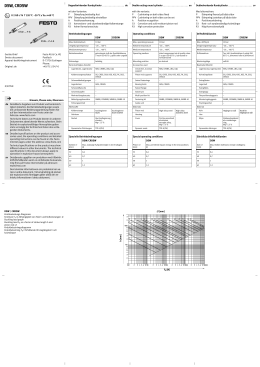
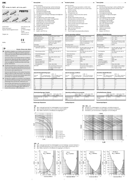
Doppeltwirkender Kompaktzylinder
ADVU
ADVUL
Geräte-Brief
Device document
Apparat-besiktningsinstrument
Original: de
ADVULQ
Festo AG & Co. KG
Postfach
D-73726 Esslingen
Phone:
+49/711/347-0
General operating conditions
Max. zulässiger Betriebsdruck
Umgebungstemperatur
Mediumstemperatur
Betriebsmedium
Max. operating pressure
Ambient temperature
Medium temperature
Operating medium
Einbaulage
Berücksichtigtes Zubehör
Lagerböcke, Lagerstücke
...................
Hinweis, Please note, Observera
de Detaillierte Angaben zum Produkt und berücksichtigtem Zubehör, die Betriebsbedingungen sowie die umfassende Bedienungsanleitung finden Sie auf den Internetseiten von Festo unter der Adresse:
www.festo.com
Technische Daten zum Produkt können in anderen
Dokumenten abweichende Werte aufweisen. Beim
Betrieb in explosionsfähiger Atmosphäre gelten stets
vorrangig die Technischen Daten des vorliegenden
Dokuments.
en Detailed specifications on the product and accessories used, the operating conditions and detailed operating instructions can be found on the Festo Internet
pages under the address:
www.festo.com
Technical specifications on the product may show
different values in other documents. The technical
specifications in this document always apply to operation in explosion-hazard atmosphere.
sv Detaljerade uppgifter om produkten med tillbehör,
driftsförhållanden samt en omfattande bruksanvisning
finns på Festos internetsidor på adressen:
www.festo.com
Den tekniska informationen om produkten kan variera
i andra dokument. Vid användning på platser där
explosionsrisk föreligger gäller alltid den tekniska
informationen i detta dokument.
Schwenkzapfen
Mehrstellungsbausatz
Befestigungsbausatz
Führungseinheit
Werkstoffe
Kolbenstange
Zylinderrohr
Bundschraube
Deckel
Dynamische Dichtungen
en
10 bar
–20 ... +60 °C
–20 ... +60 °C
getrocknete Luft der Qualitätsklasse 5 nach ISO 8573-1, geölt
oder ungeölt
beliebig
Mounting position
Accessories used
Clevis feet, trunnion support
LBN, CRLBN, LN, LNG*, CRLNG*,
LBG*, LQG, LSN*, LSNG*, LSNSG*,
LNZG, CRLNZG
SG, CRSG, SGA, KSG, KSZ, FK,
SGS, CRSGS
–
–
SNC*, SNCB*, SNCB-R3*, SNCL*,
SNCS*, SUA, SUA-R3
ZNCM*, ZNCF*
DPNC*
–
–
Piston rod supports
Swivel fastenings
Bearing bolts
Swivel flange
Swivel pin
Multi-position kit
Fastening kit
Guide unit
Materials
Piston rod
Cylinder barrel
hochlegierter Stahl
Alu-Knetlegierung,
Mg < 7,5 %
hochlegierter Stahl rostfrei
Alu-Knetlegierung,
Mg < 7,5 %
TPE-U(PU), NBR
10 bar
–20 ... +60°C
–20 ... +60°C
dried compressed air of quality
class 5 as per ISO 8573-1, lubricated or nonlubricated
as desired
LBN, CRLBN, LN, LNG*, CRLNG*,
LBG*, LQG, LSN*, LSNG*, LSNSG*,
LNZG, CRLNZG
SG, CRSG, SGA, KSG, KSZ, FK,
SGS, CRSGS
–
–
SNC*, SNCB*, SNCB-R3*, SNCL*,
SNCS*, SUA, SUA-R3
ZNCM*, ZNCF*
DPNC*
–
–
High-alloy steel
Aluminium wrought alloy,
Mg < 7.5 %
High-alloy stainless steel
Aluminium wrought alloy,
Mg < 7.5 %
TPE-U(PU), NBR
Collar screws
Cover
Dynamic Seals
Spezielle Betriebsbedingungen
ADVU/ADVUL/AD- ADVULQ
VULQ
Max. zulässige Aufprallenergie in den
Endlagen [J]
12
0,09
16
Med alternativen:
P–A Dämpning fixared på båda sidor – Positionsavkänning
A-P–A Yttergänga- Dämpning fixared på båda sidor –
Positionsavkänning
S1
Förstärkt kolvstång
S2
Genomgående kolvstång
S20 Genomgående ihålig kolvstång
R3
Högt korrosionsskydd
Allmänna driftsförhållanden
* only piston- ∅ 125 mm
Kolben-∅
[mm]
Dubbelverkande kompaktcylinder . . . . . . . . . . . . . . . . . . . . . . . . . sv
ADVU/ADVUL/ADVULQ
* nur Kolben- ∅ 125 mm
ADVU/ADVUL/ADVULQ
Max. drifttryck
Omgivningstemperatur
Medietemperatur
Driftsmedium
Monteringsläge
Beaktade tillbehör
Lagerbockar, lagerstycken
Kolvstångsfäste
Svängfästen
Lagerbult
Svängfläns
Svängtapp
Flerpositionsbyggsats
Monteringsbyggsats
Styrningsenhet
Material
Kolv
Cylinderrör
Special operating conditions
ADVU/ADVUL/AD- ADVULQ
VULQ
Max. zulässiges
Verdrehspiel der
Kolbenstange
[±
[±°]]
Max. zulässige
Verwindung der
Kolbenstange
[[°/mm]
/mm]
Piston-∅
[mm]
Max. permitted impact energy in the
end positions [j]
Flänsskruvar
Kåpa
Dynamiska tätningar
S20
0,01
0,1
1,0
0,4
12
0.09
0,1
0,01
0,2
0,9
0,3
16
20
0,14
0,01
0,45
0,8
0,25
25
0,1
0,01
0,45
0,8
32
0,4
0,04
0,8
40
0,52
0,05
50
0,64
63
Särskilda driftsförhållanden
ADVU/ADVUL/AD- ADVULQ
VULQ
Max. permitted
backlash
of piston
rod [±°]
Max. permitted distortion
of the
piston
rod
[[°/mm]
/mm]
Kolv-∅
[mm]
Max. tillåten kollisionsenergi i ändlägena [J]
Max.
tillåtet
vridmoment på
kolvstång
en [Nm]
Max.
tillåtet
vridspel
för
kolvstång
en [±°]
Max.
tillåten
distorsion för
kolvstång
en
[[°/mm]
/mm]
0.01
0.1
1.0
0.4
12
0,09
0.1
0.01
0.2
0.9
0.3
16
0,1
0,01
0,1
1,0
0,4
0,01
0,2
0,9
20
0.14
0.01
0.45
0.8
0.25
20
0,3
0,14
0,01
0,45
0,8
0,25
25
0.1
0.01
0.45
0.8
0.25
0,25
25
0,1
0,01
0,45
0,8
0,6
0,2
32
0.4
0.04
0.8
0.6
0,25
0.2
32
0,4
0,04
0,8
0,6
0,8
0,6
0,2
40
0.52
0.05
0.8
0,2
0.6
0.2
40
0,52
0,05
0,8
0,6
0,06
1,1
0,5
0,15
50
0.64
0.06
0,2
1.1
0.5
0.15
50
0,64
0,06
1,1
0,5
0,7
0,07
1,1
0,5
0,15
63
0.7
0,15
0.07
1.1
0.5
0.15
63
0,7
0,07
1,1
0,5
80
0,75
0,08
1,5
0,4
0,15
80
0,15
0.75
0.08
1.5
0.4
0.15
80
0,75
0,08
1,5
0,4
100
1
0,1
3
0,4
0,09
0,15
100
1
0,1
3
0.4
0.09
100
1
0,1
3
0,4
125
4
–
–
–
–
0,09
125
4
–
–
–
–
125
4
–
–
–
–
S20
S20
S2
Fq [N]
S1
x [mm]
x [mm]
LBN, CRLBN, LN, LNG*, CRLNG*,
LBG*, LQG, LSN*, LSNG*, LSNSG*,
LNZG, CRLNZG
SG, CRSG, SGA, KSG, KSZ, FK,
SGS, CRSGS
–
–
SNC*, SNCB*, SNCB-R3*, SNCL*,
SNCS*, SUA, SUA-R3
ZNCM*, ZNCF*
DPNC*
–
–
Höglegerat stål
Alu-smideslegering,
Mg < 7,5 %
Rostfritt höglegerat stål
Alu-smideslegering,
Mg < 7,5 %
TPE-U(PU), NBR
Max. permitted
torque at
the
piston
rod [Nm]
Einseitige Kolbenstange
Single-ended piston rod
Ensidig kolvstång
10 bar
–20 ... +60 °C
–20 ... +60 °C
Torr luft i kvalitetsklass 5 enligt
ISO 8573-1, dimsmord eller ej
dimsmord
valfritt
* endast kolv- ∅ 125 mm
Max. zulässiges
Drehmoment an
der Kolbenstange
[ ]
[Nm]
Diagramme / Diagrams / Diagram
ADVU
Max. zulässige Querkraft Fq in Abhängigkeit von der Auskragung x
Max. permitted lateral force Fq as factor of projection x
Max. tillåten tvärkraft Fq i förhållande till utkragningen x
...........................
with the variants:
P-A
Cushioning on both sides fixed – Position recognition
A-P-A Outer thread - Cushioning on both sides fixed –
Position recognition
S1
Reinforced piston rod
S2
Double-ended piston rod
S20 Double-ended hollow piston rod
R3
High corrosion protection
Allgemeine Betriebsbedingungen
ADVU/ADVUL/ADVULQ
Schwenkbefestigungen
Lagerbolzen
Schwenkflansche
672 394
Double-acting compact cylinder
mit den Varianten:
P–A Dämpfung beidseitig fest – Positionserkennung
A–P–A Außengewinde – Dämpfung beidseitig fest –
Positionserkennung
S1
verstärkte Kolbenstange
S2
durchgehende Kolbenstange
S20 durchgehend hohle Kolbenstange
R3
hoher Korrosionsschutz
Kolbenstangenaufsätze
0307NH
de
Fq [N]
II 2 GD c T4 T 120 °C –20 °C ≤ Ta ≤ +60 °C
......................
Fq [N]
ADVU, ADVUL, ADVULQ
1
2
3
4
5
6
7
8
9
aJ
aA
∅ 125 mm
∅ 100 mm
∅ 80 mm
∅ 63 mm
∅ 50 mm
∅ 40 mm
∅ 32 mm
∅ 25 mm
∅ 20 mm
∅ 16 mm
∅ 12 mm
ADVU
2
3
4
5
6
7
8
9
aJ
aA
∅ 100 mm ADVUL
∅ 80 mm
∅ 63 mm
∅ 50 mm
∅ 40 mm
∅ 32 mm
∅ 25 mm
∅ 20 mm
∅ 16 mm
∅ 12 mm
x [mm]
M [Nm]
Fq [N]
ADVUL
Max. zulässige Querkraft Fq in Abhängigkeit von der Auskragung x
Fq [N]
Einseitige Kolbenstange
Single-ended piston rod
Ensidig kolvstång
Max. zulässiges Drehmoment M in Abhängigkeit von der
Hublänge l
Max. permitted lateral force Fq as factor of projection x
Max. permitted torque M as factor of stroke length l
Max. tillåten tvärkraft Fq i förhållande till utkragningen x
Max. tillåtet vridmoment M i förhållande till slaglängden l
x [mm]
x [mm]
l [mm]
1
2
3
4
5
6
7
8
9
aJ
Fq [N]
ADVULQ
Max. zulässige Querkraft Fq in Abhängigkeit von der Auskragung x
Max. permitted lateral force Fq as factor of projection x
Max. tillåten tvärkraft Fq i förhållande till utkragningen x
Fq [N]
x [mm]
x [mm]
∅ 100 mm ADVULQ
∅ 80 mm
∅ 63 mm
∅ 50 mm
∅ 40 mm
∅ 32 mm
∅ 25 mm
∅ 20 mm
∅ 16 mm
∅ 12 mm
Cilindro compacto de doble acción
ADVU
ADVUL
Documento del dispositivo
Carnet de l’appareil
Certificato di proprietà
Original: de
ADVULQ
Festo AG & Co. KG
Postfach
D-73726 Esslingen
Phone:
+49/711/347-0
es Las especificaciones detalladas del producto y los
accesorios empleados, así como las condiciones de
uso y las instrucciones detalladas de funcionamiento
pueden hallarse en las páginas de Internet de Festo,
en la dirección: www.festo.com
Las especificaciones técnicas del producto pueden
mostrar valores diferentes en otros documentos. Las
especificaciones técnicas en este documento se aplican siempre al funcionamiento en una atmósfera con
riesgo de explosión.
fr
Vous trouverez des informations détaillées sur le produit et les accessoires appropriés ainsi que les conditions de fonctionnement et la notice d’utilisation
complète sur le site Internet de Festo à l’adresse:
www.festo.com
Les caractéristiques du produit peuvent varier d’un
document à l’autre. En cas de fonctionnement en atmosphère explosible, ce sont les Caractéristiques
techniques du présent document qui sont valables en
priorité.
it
Informazioni dettagliate circa il prodotto, i relativi
accessori e le condizioni di impiego, nonché le istruzioni per l’uso in forma estesa sono reperibili nel sito
Internet della Festo: www.festo.com
In altri documenti, le specifiche tecniche relative al
prodotto possono presentare valori diversi rispetto al
presente documento. Per l’utilizzo del prodotto in
atmosfera esplosiva si deve fare riferimento in primo
luogo ai dati tecnici del presente documento.
Avec les variantes :
P–A Amortissement fixe des deux côtés – Détection de la
position
A–P–A Filetage extérieur – Amortissement fixe des deux
côtés – Détection de la position
S1
Tige de piston renforcée
S2
Tige de piston traversante
S20 Tige de piston traversante creuse
R3
Protection anti-corrosion élevée
Cilindro compatto a doppio effetto . . . . . . . . . . . . . . . . . . . . . . . . . . it
Con le varianti:
P-A
Decelerazione fissa su entrambi i lati –
Riconoscimento di posizione
A-P-A Filetto maschio - Decelerazione fissa su entrambi i
lati – Riconoscimento di posizione
S1
Stelo rinforzato
S2
Stelo passante
S20 Stelo passante cavo
R3
Elevata protezione contro la corrosione
Condizioni di impiego generali
Presión máx. de funcionamiento
10 bar
Pression de service max.
10 bar
Temperatura ambiente
Temperatura del medio
Medio de funcionamiento
–20 ... +60 °C
–20 ... +60 °C
Aire comprimido seco, calidad
clase 5 según ISO 8573-1, con o
sin lubricación
Indifferente
Température ambiante
Température du fluide
Fluide autorisé
–20 ... +60 °C
–20 ... +60 °C
Air sec, classe de qualité selon
ISO 8573-1, lubrifié ou exempt
d’huile
Indifférente
Max. pressione di esercizio consentita
Temperatura ambiente
Temperatura del fluido
Fluido
Posición de montaje
Accesorios empleados
Caballete, brida basculante
Fijaciones basculantes
Pernos de apoyo
Brida basculante
Kit de fijación
Unidad de guía
Materiales
Vástago
Camisa del cilindro
Position de montage
Accessoires appropriés
Chapes, support à tourillon
LBN, CRLBN, LN, LNG*, CRLNG*,
LBG*, LQG, LSN*, LSNG*, LSNSG*,
LNZG, CRLNZG
SG, CRSG, SGA, KSG, KSZ, FK,
SGS, CRSGS
–
–
SNC*, SNCB*, SNCB-R3*, SNCL*,
SNCS*, SUA, SUA-R3
ZNCM*, ZNCF*
DPNC*
LBN, CRLBN, LN, LNG*, CRLNG*,
LBG*, LQG, LSN*, LSNG*, LSNSG*,
LNZG, CRLNZG
Equipements de tige de piston SG, CRSG, SGA, KSG, KSZ, FK,
SGS, CRSGS
Fixations sur pivot
–
Boulon de palier
–
Bride pivotante
SNC*, SNCB*, SNCB-R3*, SNCL*,
SNCS*, SUA, SUA-R3
Tourillon
ZNCM*, ZNCF*
Kit multipositions
DPNC*
–
–
Kit de fixation
Unité de guidage
Matériaux
Tige de piston
Tube
Acero de aleación fina
Aleación de aluminio forjado,
Mg < 7,5 %
Acero inoxidable de aleación fina
Tornillos de collarín
Tapa
Aleación de aluminio fojado,
Mg < 7,5 %
TPE-U(PU), NBR
Juntas dinámicas
Max. Energía del impacto permitida en
las posiciones finales [J]
12
0,09
16
Acier fortement allié
Alliage corroyé d’aluminium,
Mg < 7,5 %
Acier fortement allié inoxydable
Capot
ADVU/ADVUL/ADVULQ
Posizione di montaggio
Accessori in dotazione
Supporti a cerniera, supporti
Raccordi per steli
Fissaggi a cerniera
Perni assiali
Flange oscillanti
Perni oscillanti
Kit di montaggio per cilindri
a più posizioni
Kit di fissaggio
Unità di guida
Materiali
Stelo del cilindro
Canna del cilindro
Viti a testa cilindrica
Alliage corroyé d’aluminium,
Mg < 7,5 %
TPE-U(PU), NBR
Joints dynamiques
* seulement ∅ de piston 125 mm
Condiciones especiales de funcionamiento
ADVU/ADVUL/AD- ADVULQ
VULQ
∅ del
émbolo[mm]
–
–
Vis taraudées
* Sólo émbolos de 125 mm de- ∅
Holgura
máx. permisible
del
vástago
[±
[±°]]
Distorsión máx.
permisible del
vástago
[[°/mm]
/mm]
∅ de
piston
[mm]
Impact max. admissible en position de fin
de course [J]
0,01
0,1
1,0
0,4
12
0,09
0,1
0,01
0,2
0,9
0,3
16
20
0,14
0,01
0,45
0,8
0,25
25
0,1
0,01
0,45
0,8
32
0,4
0,04
0,8
40
0,52
0,05
50
0,64
63
Testata
Guarnizioni dinamiche
Déformation max.
admissible de la
tige de
piston
[°/
[°/mm]
]
∅ del
pistone
[mm]
Max. energia di impatto consentita a
fine corsa [J]
S20
Jeu de
torsion
max. admissible
de la tige
de piston
[ °]
[±°]
0,01
0,1
1,0
0,4
12
0,09
0,1
0,01
0,2
0,9
0,3
16
0,1
20
0,14
0,01
0,45
0,8
0,25
20
0,25
25
0,1
0,01
0,45
0,8
0,25
0,6
0,2
32
0,4
0,04
0,8
0,6
0,8
0,6
0,2
40
0,52
0,05
0,8
0,06
1,1
0,5
0,15
50
0,64
0,06
0,7
0,07
1,1
0,5
0,15
63
0,7
80
0,75
0,08
1,5
0,4
0,15
80
100
1
0,1
3
0,4
0,09
125
4
–
–
–
–
–
–
Acciaio fortemente legato
Lega di alluminio per lavorazione
plastica, Mg < 7,5 %
Acciaio fortemente legato inossidabile
Lega di alluminio per lavorazione
plastica, Mg < 7,5 %
TPE-U(PU), NBR
Max.
gioco torsionale
consentito sullo
stelo [±°]
[± ]
Max. deformazione
consentita dello
stelo
[°/
[°/mm]
]
0,01
0,1
1,0
0,4
0,01
0,2
0,9
0,3
0,14
0,01
0,45
0,8
0,25
25
0,1
0,01
0,45
0,8
0,25
0,2
32
0,4
0,04
0,8
0,6
0,2
0,6
0,2
40
0,52
0,05
0,8
0,6
0,2
1,1
0,5
0,15
50
0,64
0,06
1,1
0,5
0,15
0,07
1,1
0,5
0,15
63
0,7
0,07
1,1
0,5
0,15
0,75
0,08
1,5
0,4
0,15
80
0,75
0,08
1,5
0,4
0,15
100
1
0,1
3
0,4
0,09
100
1
0,1
3
0,4
0,09
125
4
–
–
–
–
125
4
–
–
–
–
S2
Fq [N]
LBN, CRLBN, LN, LNG*, CRLNG*,
LBG*, LQG, LSN*, LSNG*, LSNSG*,
LNZG, CRLNZG
SG, CRSG, SGA, KSG, KSZ, FK,
SGS, CRSGS
–
–
SNC*, SNCB*, SNCB-R3*, SNCL*,
SNCS*, SUA, SUA-R3
ZNCM*, ZNCF*
DPNC*
Max. coppia consentita
sullo
stelo
[Nm]
S20
S20
S1
x [mm]
x [mm]
–20 ... +60 °C
–20 ... +60 °C
Aria compressa essiccata, classe
di qualità 5 a norma ISO 8573-1,
lubrificata o non lubrificata
qualsiasi
Condizioni di impiego specifiche
ADVU/ADVUL/AD- ADVULQ
VULQ
Couple
max. admissible
sur la
tige de
piston
[N ]
[Nm]
Vástago simple
Tige de piston unilatérale
Stelo su un lato
10 bar
* solo ∅ del pistone 125 mm
Conditions de fonctionnement spéciales
ADVU/ADVUL/AD- ADVULQ
VULQ
Par
máximo
permitido en el
vástago
[Nm]
Diagramas / Diagrammes / Diagrammi
ADVU
Fuerza lateral máx. permitida Fq en función del voladizo x
Force transversale Fq max. admissible en fonction de la
saillie x
Max. forza trasversale consentita Fq in funzione della sporgenza x
fr
Conditions de fonctionnement générales
ADVU/ADVUL/ADVULQ
Pasador basculante
Kit multiposicional
Nota, Note, Nota
................................
Condiciones generales de funcionamiento
ADVU/ADVUL/ADVULQ
672 394
.......................................
Vérin compact à double effet
Con las variantes:
P–A Amortiguación fija en ambos lados– Reconocimiento
de posición
A–P–A Rosca exterior – Amortiguación fija en ambos lados
Reconocimiento de posición
S1
Vástago reforzado
S2
Doble vástago
S20 Doble vástago hueco
R3
Alta resistencia a la corrosión
Fijaciones del vástago
0307NH
es
Fq [N]
II 2 GD c T4 T 120 °C –20 °C ≤ Ta ≤ +60 °C
........................
Fq [N]
ADVU, ADVUL, ADVULQ
1
2
3
4
5
6
7
8
9
aJ
aA
∅ 125 mm
∅ 100 mm
∅ 80 mm
∅ 63 mm
∅ 50 mm
∅ 40 mm
∅ 32 mm
∅ 25 mm
∅ 20 mm
∅ 16 mm
∅ 12 mm
ADVU
2
3
4
5
6
7
8
9
aJ
aA
∅ 100 mm ADVUL
∅ 80 mm
∅ 63 mm
∅ 50 mm
∅ 40 mm
∅ 32 mm
∅ 25 mm
∅ 20 mm
∅ 16 mm
∅ 12 mm
x [mm]
M [Nm]
Fq [N]
ADVUL
Fuerza lateral máx. permitida Fq en función del voladizo x
Fq [N]
Vástago simple
Tige de piston unilatérale
Stelo su un lato
Par máx. M permitido en función de la carrera l
Force transversale Fq max. admissible en fonction de la
saillie x
Couple M max. admissible en fonction de la longueur de
course l
Max. forza trasversale consentita Fq in funzione della sporgenza x
Max. coppia consentita M in funzione della corsa l
x [mm]
x [mm]
l [mm]
1
2
3
4
5
6
7
8
9
aJ
Fq [N]
ADVULQ
Fuerza lateral máx. permitida Fq en función del voladizo x
Force transversale Fq max. admissible en fonction de la
saillie x
Max. forza trasversale consentita Fq in funzione della sporgenza x
Fq [N]
x [mm]
x [mm]
∅ 100 mm ADVULQ
∅ 80 mm
∅ 63 mm
∅ 50 mm
∅ 40 mm
∅ 32 mm
∅ 25 mm
∅ 20 mm
∅ 16 mm
∅ 12 mm
Scaricare